EP4068717B1 - Procédé de commande de noeud d'extrémité, noeud, et système de calcul d'extrémité - Google Patents
Procédé de commande de noeud d'extrémité, noeud, et système de calcul d'extrémité Download PDFInfo
- Publication number
- EP4068717B1 EP4068717B1 EP20910742.4A EP20910742A EP4068717B1 EP 4068717 B1 EP4068717 B1 EP 4068717B1 EP 20910742 A EP20910742 A EP 20910742A EP 4068717 B1 EP4068717 B1 EP 4068717B1
- Authority
- EP
- European Patent Office
- Prior art keywords
- edge node
- edge
- node
- nodes
- deployed
- Prior art date
- Legal status (The legal status is an assumption and is not a legal conclusion. Google has not performed a legal analysis and makes no representation as to the accuracy of the status listed.)
- Active
Links
Images


Classifications
-
- H—ELECTRICITY
- H04—ELECTRIC COMMUNICATION TECHNIQUE
- H04L—TRANSMISSION OF DIGITAL INFORMATION, e.g. TELEGRAPHIC COMMUNICATION
- H04L41/00—Arrangements for maintenance, administration or management of data switching networks, e.g. of packet switching networks
- H04L41/08—Configuration management of networks or network elements
- H04L41/0893—Assignment of logical groups to network elements
-
- H—ELECTRICITY
- H04—ELECTRIC COMMUNICATION TECHNIQUE
- H04L—TRANSMISSION OF DIGITAL INFORMATION, e.g. TELEGRAPHIC COMMUNICATION
- H04L41/00—Arrangements for maintenance, administration or management of data switching networks, e.g. of packet switching networks
- H04L41/08—Configuration management of networks or network elements
- H04L41/0894—Policy-based network configuration management
-
- H—ELECTRICITY
- H04—ELECTRIC COMMUNICATION TECHNIQUE
- H04L—TRANSMISSION OF DIGITAL INFORMATION, e.g. TELEGRAPHIC COMMUNICATION
- H04L43/00—Arrangements for monitoring or testing data switching networks
- H04L43/08—Monitoring or testing based on specific metrics, e.g. QoS, energy consumption or environmental parameters
- H04L43/0823—Errors, e.g. transmission errors
-
- H—ELECTRICITY
- H04—ELECTRIC COMMUNICATION TECHNIQUE
- H04L—TRANSMISSION OF DIGITAL INFORMATION, e.g. TELEGRAPHIC COMMUNICATION
- H04L67/00—Network arrangements or protocols for supporting network services or applications
- H04L67/01—Protocols
- H04L67/02—Protocols based on web technology, e.g. hypertext transfer protocol [HTTP]
- H04L67/025—Protocols based on web technology, e.g. hypertext transfer protocol [HTTP] for remote control or remote monitoring of applications
-
- H—ELECTRICITY
- H04—ELECTRIC COMMUNICATION TECHNIQUE
- H04L—TRANSMISSION OF DIGITAL INFORMATION, e.g. TELEGRAPHIC COMMUNICATION
- H04L67/00—Network arrangements or protocols for supporting network services or applications
- H04L67/01—Protocols
- H04L67/10—Protocols in which an application is distributed across nodes in the network
- H04L67/1001—Protocols in which an application is distributed across nodes in the network for accessing one among a plurality of replicated servers
-
- H—ELECTRICITY
- H04—ELECTRIC COMMUNICATION TECHNIQUE
- H04L—TRANSMISSION OF DIGITAL INFORMATION, e.g. TELEGRAPHIC COMMUNICATION
- H04L67/00—Network arrangements or protocols for supporting network services or applications
- H04L67/01—Protocols
- H04L67/10—Protocols in which an application is distributed across nodes in the network
- H04L67/1095—Replication or mirroring of data, e.g. scheduling or transport for data synchronisation between network nodes
-
- H—ELECTRICITY
- H04—ELECTRIC COMMUNICATION TECHNIQUE
- H04L—TRANSMISSION OF DIGITAL INFORMATION, e.g. TELEGRAPHIC COMMUNICATION
- H04L41/00—Arrangements for maintenance, administration or management of data switching networks, e.g. of packet switching networks
- H04L41/12—Discovery or management of network topologies
-
- H—ELECTRICITY
- H04—ELECTRIC COMMUNICATION TECHNIQUE
- H04L—TRANSMISSION OF DIGITAL INFORMATION, e.g. TELEGRAPHIC COMMUNICATION
- H04L43/00—Arrangements for monitoring or testing data switching networks
- H04L43/08—Monitoring or testing based on specific metrics, e.g. QoS, energy consumption or environmental parameters
- H04L43/0805—Monitoring or testing based on specific metrics, e.g. QoS, energy consumption or environmental parameters by checking availability
- H04L43/0817—Monitoring or testing based on specific metrics, e.g. QoS, energy consumption or environmental parameters by checking availability by checking functioning
Definitions
- Embodiments of this application relate to the field of edge computing technologies, and in particular, to a method for controlling an edge node and a control node.
- edge computing has been successfully implemented and applied to a plurality of fields such as a smart city, industrial manufacturing, and logistics.
- a terminal layer transmits a large amount of user data to an edge computing layer for preliminary processing, and then the edge computing layer synchronizes a relatively small amount of data obtained through preliminary processing to a cloud computing layer for further processing. This can improve data processing efficiency.
- the cloud computing layer is further configured to control the edge computing layer in addition to processing the data from the edge computing layer.
- the cloud computing layer cannot control the edge computing layer, normal work of the edge computing layer may be affected.
- US 2018/0062914 A1 discloses a method for providing redundancy and fast convergence for modules operating in a network.
- Embodiments of this application provide a method for controlling an edge node, a node, and an edge computing system, to control an edge node in an edge node cluster when a control node cannot control the edge node in the edge node cluster.
- the invention is defined in the independent claims. Advantageous features are defined in the dependent claims.
- the control node divides the plurality of edge nodes included in the edge node cluster into the N edge node sets, where each edge node set includes at least two edge nodes, and N is a positive integer.
- the control node selects the M second edge nodes from the first edge node set, and sends the control rule to the M second edge nodes, where the control rule indicates the second edge node to perform fault detection on the first edge node, the first edge node belongs to the first edge node set, the first edge node set is one of the N edge node sets, and M is a positive integer.
- the control node cannot control the first edge node in the edge node cluster, the second edge node can detect a fault status of the first edge node.
- Embodiments of this application provide a method for controlling an edge node, a node, and an edge computing system, to control an edge node in an edge node cluster when the edge node cluster is in an offline scenario or a weak network scenario.
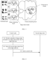
- FIG. 1 is a schematic diagram of an architecture of an edge computing system according to an embodiment of this application.
- the edge computing system includes a terminal layer, an edge computing layer, and a cloud computing layer.
- the edge computing layer is in communication connection to both the terminal layer and the cloud computing layer over communications networks.
- the terminal layer includes a plurality of terminal devices. For example, in FIG.
- the terminal layer may specifically include terminal devices such as a vehicle-mounted terminal, a notebook computer, a smartwatch, a smartphone, a tablet computer, and a smart television;
- the edge computing layer includes at least one edge node cluster, one edge node cluster includes at least two edge nodes, and the edge node may be an edge gateway, an edge controller, an edge server, and the like;
- the cloud computing layer includes at least one cloud server cluster.
- the communications network between the edge computing layer and the terminal layer may be a wired communications network, or may be a wireless communications network.
- the communications network may be a 5th-generation (5th-Generation, 5G) mobile communication technology system, a long term evolution (long term evolution, LTE) system, a global system for mobile communications (global system for mobile communications, GSM), a code division multiple access (code division multiple access, CDMA) network, or a wideband code division multiple access (wideband code division multiple access, WCDMA) network.
- the communications network may be another communications network or communications system, for example, wireless fidelity (wireless fidelity, Wi-Fi), or the like.
- the communications network between the edge computing layer and the cloud computing layer is usually a metropolitan area network.
- the cloud computing layer is used to further process data preliminarily processed at the edge computing layer.
- the cloud computing layer is further used to control the edge computing layer, specifically including managing and scheduling the edge node cluster.
- a control node is usually disposed at the cloud computing layer. The control node is used to perform centralized status management, task allocation, task scheduling, and the like on the edge node in the edge node cluster.
- control node cannot control the edge node cluster.
- the control node cannot control the edge node in the edge node cluster.
- the edge computing layer is in an offline scenario or a weak network scenario.
- the control node cannot control the edge node in the edge node cluster.
- embodiments of this application provide a method for controlling an edge node.
- the method can be used to control the edge node in the edge node cluster.
- the method in embodiments of this application may also be used to assist the control node to control the edge node in the edge computing cluster.
- the following describes the method in detail.
- the control node controls the edge node in the edge node cluster
- the other is that the edge node cluster controls the internal edge nodes.
- the following first describes the method from a control node side.
- FIG. 2 is a schematic diagram of an embodiment of a method for controlling an edge node according to an embodiment of this application. As shown in FIG. 2 , embodiments of this application provide the embodiment of the method for controlling the edge node, applied to a control node, and the embodiment includes the following steps.
- Step 101 The control node divides a plurality of edge nodes included in an edge node cluster into N edge node sets.
- Each edge node set includes at least two edge nodes, and N is a positive integer.
- the two edge node sets may include same edge nodes.
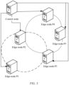
- FIG. 3 is a schematic diagram of edge node sets in an edge node cluster according to an embodiment of this application.
- the edge node cluster includes edge nodes P1, P2, P3, P4, and P5, which are divided into two edge node sets.
- One edge node set includes the edge nodes P1, P2, and P3, the other edge node set includes the edge nodes P2, P3, P4, and P5, and the two edge node sets include the same edge nodes P2 and P3.
- control node there are a plurality of methods for the control node to divide the edge node cluster into the N edge node sets, and the methods may be selected according to an actual requirement. This is not limited in this embodiment of this application.
- the edge node cluster may be divided into the N edge node sets based on an actual situation of each edge node.
- the actual situation includes but is not limited to a status of the edge node, a resource of the edge node, storage space (including memory and disk space) of the edge node, CPU usage of the edge node, and memory usage of the edge node.
- the status of the edge node may be a faulty state or a non-faulty state.
- a first edge node set in the N edge node sets is used as an example. Non-faulty edge nodes whose resources, storage space, and CPU usage all meet a preset condition may be selected from the edge node cluster, to form the first edge node set.
- the control node may further divide the edge node cluster into the N edge node sets based on the to-be-deployed application images.
- control node divides the plurality of edge nodes included in the edge node cluster into the N edge node sets includes: First, the control node determines a quantity of edge node sets based on a quantity of to-be-deployed application images. For example, one application image corresponds to one edge node set. Then, the control node selects appropriate edge nodes from the edge node cluster based on a type of an application image to form an edge node set.
- control node divides the plurality of edge nodes included in the edge node cluster into the N edge node sets includes: The control node selects, based on a to-be-deployed application image and an application image that has been deployed on the plurality of edge nodes included in the edge node cluster, K edge nodes from the plurality of edge nodes to form the first edge node set, where K is a positive integer.
- affinity and anti-affinity between the first application image and the second application image may be considered in a process of forming the first edge node set corresponding to the first application image. For example, if there is affinity between the first application image and the second application image, edge nodes on which the second application image has been deployed may be selected as much as possible to form the first edge node set. If there is anti-affinity between the first application image and the second application image, edge nodes on which the second application image is not deployed may be selected as much as possible to form the first edge node set.
- Step 102 The control node selects M second edge nodes from the first edge node set, where the first edge node set is one of the N edge node sets, and M is a positive integer.
- the control node selects the M second edge nodes from the first edge node set. Specifically, the control node may select the M second edge nodes according to a specific rule, or may randomly select the M second edge nodes. A quantity K of edge nodes in the first edge node set is greater than M.
- the following uses an example to describe a process of selecting the M second edge nodes according to the specific rule.
- control node After the control node selects, based on the to-be-deployed application image and the application image that has been deployed on the plurality of edge nodes included in the edge node cluster, the K edge nodes from the plurality of edge nodes to form the first edge node set, the control node enables the K edge nodes to form a hash ring.
- FIG. 4 is a schematic diagram of an embodiment of a hash ring according to an embodiment of this application.
- the hash ring includes six edge nodes, and the six edge nodes form relative location relationships in the hash ring.
- the control node can select the M second edge nodes from the first edge node set based on the hash ring, to perform fault detection on a first edge node.
- the M second edge nodes there may be a plurality of relative location relationships between the M second edge nodes and the first edge node in the hash ring.
- the first edge node and at least one second edge node are adjacent in the hash ring.
- the first edge node is adjacent to the second edge node.
- M is equal to 2
- the two second edge nodes may be adjacent to the first edge node, or one of the two second edge nodes may be adjacent to the first edge node, and the other second edge node is distributed relative to the first edge node.
- M is greater than 2 only one second edge node or two second edge nodes can be adjacent to the first edge node.
- control node may further deliver information about the hash ring to each of the K edge nodes, so that each edge node can determine a location of another edge node in the hash ring based on the information about the hash ring.
- Step 103 The control node sends a control rule to the M second edge nodes, where the control rule indicates the second edge node to perform fault detection on the first edge node, and the first edge node belongs to the first edge node set.
- control node After selecting the M second edge nodes, the control node sends the control rule to the M second edge nodes, so that the second edge node performs fault detection on the first edge node.
- M may have a plurality of values.
- M may be set to be greater than or equal to 2. In this way, at least two second edge nodes perform fault detection on the first edge node.
- M may be set to a small value, for example, M may be 2 or 3.
- Different first edge nodes may correspond to M same or different second edge nodes.
- M is greater than or equal to 2
- the different first edge nodes correspond to M different second edge nodes.
- two second edge nodes correspond to one first edge node
- two second edge nodes correspond to another first edge node
- different first edge nodes may correspond to different quantities of second edge nodes. For example, one first edge node corresponds to two second edge nodes, and another first edge node corresponds to three second edge nodes.
- edge nodes in the first edge node set may be responsible for performing fault detection on different quantities of edge nodes. For example, it is assumed that the first edge node set includes four edge nodes, one edge node may need to perform fault detection on three other edge nodes, two edge nodes need to perform fault detection on two other edge nodes, and the other edge node does not need to perform fault detection on other edge nodes.
- the second edge node may be appropriately selected and the control rule may be configured, so that each edge node in the first edge node set performs fault detection on another edge node. Further, each edge node may need to detect a same quantity of other edge nodes. For example, when M is equal to 2, the control rule may be configured, so that each edge node needs to perform fault detection on two other edge nodes.
- the control node divides the plurality of edge nodes in the edge node cluster into the N edge node sets, selects the second edge node from each edge node set, and then sends the control rule to the second edge node, so that the second edge node performs fault detection on the first edge node in the edge node set in which the second edge node is located.
- the second edge node in the edge node cluster can perform fault detection on the first edge node, thereby sensing a fault status of the first edge node in time.
- the second edge nodes corresponding to the different first edge nodes may be different, no edge node in the edge node cluster is responsible for performing fault detection on all other edge nodes, which avoids a case in which a fault status of another edge node cannot be sensed because the edge node responsible for fault detection is faulty.
- the first edge nodes corresponding to the second edge nodes may be only some edge nodes in the edge node cluster. Compared with a solution in which the second edge node needs to perform fault detection on all the edge nodes in the edge node cluster other than the second edge node, this embodiment of this application can reduce load of the second edge node.
- control node indicates the second edge node to perform fault detection on the first edge node.
- control node deploys the application images in the edge node cluster.
- the control node deploys the to-be-deployed application images on the N edge node sets, where the to-be-deployed application images are in a one-to-one correspondence with the edge node sets.
- edge node sets may include same edge nodes, two or more types of application images may be deployed on a same edge node.
- the edge node cluster shown in FIG. 3 is used as an example.
- the edge node P2 and the edge node P3 in the edge node cluster both exist in two edge node sets. If one type of application image is deployed in each of the two edge node sets, two types of application images may be deployed on both the edge node P2 and the edge node P3.
- an application image may be deployed on each edge node in the edge node set.
- each edge node can run the application image to execute a corresponding task.
- an application image may be deployed on some edge nodes in the edge node set.
- the edge nodes in the edge node set are first divided into two types: an initial edge node and an alternative edge node. For example, as shown in FIG. 4 , two black edge nodes on the left of the hash ring shown in FIG. 4 may be used as alternative edge nodes, and remaining four edge nodes are used as initial edge nodes.
- an application image is deployed on each initial edge node, but no application image is deployed on the alternative edge node.
- the initial edge node may run the application image to execute a corresponding task.
- the alternative edge node is used for scheduling.
- the edge node can obtain another part of the image from another edge node to form the application image.
- the control node deploys X layered images included in the to-be-deployed application image on L edge nodes in the first edge node set, where at least one layered image is deployed on each of the L edge nodes, and both L and X are positive integers greater than 1.
- the at least one layered image deployed on each edge node may include the base image in the to-be-deployed application image, and may include a part of the upper-layer software package image.
- FIG. 5 is a schematic diagram of an embodiment of a to-be-deployed application image according to an embodiment of this application.
- the application image includes four layered images, and at least one of the four layered images may be deployed on each edge node.
- a same quantity or different quantities of layered images may be deployed on different edge nodes.
- L is less than the quantity K of edge nodes in the first edge node set, it indicates that there is an alternative edge node in the first edge node set, and no layered image is deployed on the alternative edge node.
- a same layered image may be deployed on a plurality of edge nodes, that is, a same layered image corresponds to a plurality of copies. For example, if the same layered image is deployed on three edge nodes at the same time, the layered image corresponds to three copies. To ensure balance between the layered images, each layered image may correspond to a same quantity of copies.
- FIG. 6 is a schematic diagram of an embodiment of deploying a to-be-deployed application image according to an embodiment of this application.
- a first edge node set includes edge nodes A, B, C, and D
- the to-be-deployed application image includes layered images a, b, c, and d
- each layered image corresponds to three copies
- the layered images b and d are deployed on the edge node A
- the layered images a, b, c, and d are deployed on the edge node B
- the layered images a, b, and c are deployed on the edge node C
- the layered images a, c, and d are deployed on the edge node D.
- the layered image b is used as an example.
- the layered image b is separately deployed on the edge nodes A, B, and C.
- the layered images a, b, c, and d are deployed only on the edge node B, that is, the complete application image is deployed on the edge node B. Therefore, the edge node B can directly run the stored application image, without obtaining the layered image from another edge node, to execute the corresponding task.
- the layered images b and d are deployed on the edge node A. Therefore, the edge node A needs to obtain the layered images a and c from another edge node to form the complete application image.
- the layered images a and c may be obtained from any edge node of the edge nodes B, C, and D. Situations of the edge node C and the edge node D are similar to the situation of the edge node A. For specific understanding, refer to related description of the edge node A.
- the first edge node set is one of the N edge node sets.
- image deployment may be performed by using a same method as the method used in the first edge node set.
- a layered image is separately deployed on a plurality of edge nodes, or the complete application image may be directly deployed on a plurality of edge nodes. This is not limited in this embodiment of this application.
- FIG. 7 is a schematic diagram of an embodiment of deploying an application image according to an embodiment of this application. As shown in FIG. 7 , that a control node deploys X layered images included in a to-be-deployed application image on L edge nodes in a first edge node set includes the following steps.
- Step 201 The control node establishes a target function for deploying application images for N edge node sets.
- Step 202 The control node determines an image deployment solution based on a preset optimization algorithm and the target function.
- step 201 the control node establishes the target function.
- step 202 the control node performs optimization solving on the target function based on the optimization algorithm, to obtain the image deployment solution in which the X layered images included in the to-be-deployed application image can be deployed on the L edge nodes in the first edge node set.
- the obtained image deployment solution may be an optimal image deployment solution.
- the obtained image deployment solution may also be a suboptimal image deployment solution because there are a large quantity of deployment solutions.
- Step 203 The control node deploys, according to the image deployment solution, the X layered images included in the to-be-deployed application image on the L edge nodes in the first edge node set.
- control node first establishes the target function for deploying the application images for the N edge node sets, and then obtains the image deployment solution through optimization solving on the target function. Finally, the control node can deploy at least one layered image on each of the L edge nodes according to the image deployment solution obtained through optimization solving.
- control node establishes the target function for deploying the application images for the N edge node sets includes: First, the control node establishes a first indicator and a second indicator, where the first indicator indicates reliability of deploying the application images for the N edge node sets, and the second indicator indicates balance of deploying the application images for the N edge node sets.
- the control node establishes the target function based on the first indicator and the second indicator.
- a constraint condition is that the quantity of edge nodes F i , j ,r is greater than or equal to 1 and less than or equal to Z, and 0 ⁇ T W ⁇ R W .
- the control node After the control node deploys the X layered images included in the to-be-deployed application image on the L edge nodes in the first edge node set, the control node sends deployment information of the to-be-deployed application image to the edge nodes in the first edge node set.
- the deployment information of the application image includes deployment of a layered image in the to-be-deployed application image deployed on each of the L edge nodes.
- each edge node in the first edge node set can determine, based on the deployment information, the layered image deployed on the edge node of the L edge nodes.
- the edge node can obtain a corresponding layered image from another edge node based on the deployment information, to form the application image.
- FIG. 8 is a schematic diagram of another embodiment of a method for controlling an edge node according to an embodiment of this application.
- Embodiments of this application provide the another embodiment of the method for controlling the edge node, applied to an edge node cluster.
- the control node divides the edge node cluster.
- the plurality of edge nodes included in the edge node cluster are divided into the N edge node sets, where each edge node set includes the at least two edge nodes.
- the first edge node set in the N edge node sets includes the second edge node, the second edge node stores the control rule, and there may be M second edge nodes, where both M and N are positive integers.
- the method includes the following steps.
- Step 301 The second edge node determines a first edge node from the first edge node set according to the control rule. Because the control rule indicates the second edge node to perform fault detection on the first edge node, the second edge node can determine the first edge node according to the control rule.
- the control rule may include a mapping relationship between the second edge node and the first edge node.
- edge nodes in the first edge node set form a hash ring.
- the control node delivers the information about the hash ring to each edge node in the first edge node set, so that each edge node can determine the location of the another edge node in the hash ring based on the information about the hash ring. Therefore, the second edge node can determine the first edge node based on the information about the hash ring and the relative location relationships between the second edge node and the first edge node in the hash ring. For example, as shown in FIG.
- the first edge node and the second edge node are adjacent in the hash ring, that is, the second edge node may determine an adjacent edge node in the hash ring as the first edge node.
- the first edge node and the second edge node may also be relatively distributed in the hash ring, that is, the second edge node may determine an edge node opposite to the first edge node in the hash ring as the first edge node.
- Step 302 The second edge node performs fault detection on the first edge node.
- the second edge node After determining the first edge node, the second edge node performs fault detection on the first edge node.
- the fault detection may be performed periodically. There are a plurality of specific fault detection methods. This is not limited in this embodiment of this application.
- the second edge node may implement fault detection on the first edge node through heartbeat detection. Specifically, the second edge node sends a request message to the first edge node, where the request message may carry related information of the second edge node, and the related information may include an IP address of the second edge node. If the second edge node does not receive a response message corresponding to the request message within a preset time period, it may be determined that the first edge node is faulty.
- the second edge node when the control node cannot perform fault detection on the first edge node in the first edge node set, the second edge node can perform fault detection on the first edge node according to the control rule, thereby sensing a fault status of the first edge node in time.
- the second edge nodes corresponding to the different first edge nodes may be different, no edge node in the edge node cluster is responsible for performing fault detection on all other edge nodes, which avoids a case in which a fault status of another edge node cannot be sensed because the edge node responsible for fault detection is faulty.
- the first edge nodes corresponding to the second edge nodes may be only some edge nodes in the edge node cluster. Compared with a solution in which the second edge node needs to perform fault detection on all the edge nodes in the edge node cluster other than the second edge node, this embodiment of this application can reduce load of the second edge node.
- edge node cluster needs to run the application image to execute a corresponding task, and there are a plurality of cases of deploying the application images in the edge node cluster.
- one application image is deployed on each of the N edge node sets.
- the first edge node set is used as an example. Assuming that an application image is deployed in the first edge node set, the application image may be deployed on each edge node in the first edge node set, or the application image is deployed on some edge nodes in the first edge node set.
- the application image includes the base image and the upper-layer software package image, and the upper-layer software package image may be divided into the plurality of parts. Therefore, in the another embodiment of the method for controlling the edge node provided in embodiments of this application, at least one of the X layered images included in the application image is deployed on each of the L edges in the first edge node set, and both L and X are positive integers greater than 1.
- the at least one layered image deployed on each edge node may include the base image in the application image, and may include a part of the upper-layer software package image.
- Each edge node in the first edge node set stores deployment information of the application image, and the deployment information of the application image includes the deployment of the layered image in the application image deployed on each of the L edge nodes.
- the method in this embodiment further includes the following steps.
- the second edge node obtains (X-H) layered images from another edge node in the L edge nodes based on the deployment information of the application image, to form the application image, where H is a positive integer, and X is a positive integer greater than H.
- the second edge node may determine, based on the deployment information of the application image, that the layered images a, b, c, and d are deployed on an edge node B, the layered images a, b, and c are deployed on an edge node C, and the layered images a, c, and d are deployed on an edge node D.
- the second edge node can obtain the layered images a and c from any one of the edge nodes B, C, and D, to form the application image. After obtaining the application image, the second edge node can run the application image to execute a corresponding task.
- the second edge node can directly run the application image including the locally stored X layered images, without obtaining a layered image from another edge node, to execute a corresponding task.
- the second edge node may be used as an alternative edge node for scheduling.
- the foregoing describes fault detection performed by the second edge node on the first edge node, and describes the deployment of the application image in the first edge node set. Based on the deployment, the following describes a scheduling process after the first edge node is faulty.
- FIG. 9 is a schematic diagram of an embodiment of a scheduling process according to an embodiment of this application. The method in this embodiment further includes the following steps.
- Step 401 If the first edge node is faulty, the second edge node determines, based on the deployment information of the application image, deployment of the layered image in the application image deployed on the first edge node.
- the first edge node set there may be one or more second edge nodes.
- the current second edge node detects that the first edge node is faulty, it can be determined that the first edge node is faulty.
- a corresponding rule may be set, so that only when at least E second edge nodes detect that the first edge node is faulty, it can be determined that the first edge node is faulty, where E may be 1, or may be greater than or equal to 2.
- the deployment of the layered image in the application image may be that at least one layered image in the application image is deployed on the first edge node, or may be that no at least one layered image in the application image is deployed on the first edge node.
- Step 402 If the at least one layered image is deployed on the first edge node, the second edge node selects an edge node from the first edge node set to execute a task of the first edge node.
- the at least one layered image is deployed on the first edge node, it indicates that the first edge node runs the application image to execute the corresponding task. Therefore, an edge node needs to be reselected to perform the task instead of the first edge node.
- the plurality of factors may include a status of the edge node, a resource of the edge node, a memory of the edge node, disk space of the edge node, CPU usage of the edge node, memory usage of the edge node, affinity between an application image on the edge node and the application image corresponding to a layered image on the first edge node, anti-affinity between the application image on the edge node and the application image corresponding to the layered image on the first edge node, a quantity of types of application images on the edge node, a degree of exclusion between the application image on the edge node and the application image corresponding to the layered image on the first edge node, storage space occupied by the application image on the edge node, and the like.
- the second edge node may calculate a deployment weight of the second edge node based on the foregoing plurality of factors, receive a deployment weight of another edge node in the first edge node set, and finally select, based on the deployment weight of the second edge node and the deployment weight of the another edge node in the first edge node set, the edge node to replace the first edge node to execute the task, thereby ensuring that the selected edge node is an edge node most appropriate for executing the task of the first edge node.
- the current second edge node may select one edge node to replace the first edge node to execute the task.
- the first edge node is faulty, all second edge nodes can usually detect that the first edge node is faulty. Therefore, the current second edge node can negotiate with another second edge node to select one edge node to replace the first edge node to execute the task.
- the second edge node may directly perform selection from all other edge nodes in the first edge node set other than the first edge node, or may sequentially perform selection according to a specific rule.
- a second edge node meeting a preset condition may be first selected from all the second edge nodes to replace the first edge node to execute the task.
- the second edge node does not need to send a fault message to the another edge node other than the second edge nodes in the first edge node set, where the fault message is used to indicate that the first edge node is faulty. This can reduce interaction between edge nodes, and reduce load of the edge node.
- an edge node may be selected from other edge nodes other than the second edge nodes in the first edge node set to replace the first edge node to execute the task. Specifically, some edge nodes may be selected from the other edge nodes other than the second edge nodes in the first edge node set, and then, whether there is an edge node meeting the preset condition in the selected edge nodes is determined. If there is the edge node meeting the preset condition, the edge node meeting the preset condition is selected to replace the first edge node to execute the task. If there is no edge node meeting the preset condition, selection continues to be performed on remaining edge nodes.
- FIG. 10 is a schematic diagram of an embodiment of a hash ring corresponding to a first edge node according to an embodiment of this application.
- the hash ring includes one edge node V1, two edge nodes V2, two edge nodes V3, and one edge node V4. It is assumed that a first edge node is the edge node V1, and second edge nodes is the edge nodes V2. If the edge node V1 is faulty, the two edge nodes V2 may first negotiate to select one from the two edge nodes V2 to replace the edge node V1 to execute a task.
- an edge node may be selected from the two edge nodes V3 adjacent to the two edge nodes V2 to replace the edge node V1 to execute the task. If neither of the two edge nodes V3 meets the preset condition, whether the edge node V4 meets the preset condition is determined. If the edge node V4 meets the preset condition, the edge node V4 is used to replace the edge node V1 to execute the task.
- the second edge node selects the edge node from the first edge node set to replace the first edge node to execute the task. It should be noted that when there is no edge node meeting the preset condition in the first edge node set, that is, there is no edge node in the first edge node set that can replace the first edge node to execute the task, the second edge node can further select the edge node from the another edge node set to replace the first edge node to execute the task, and a specific selection process is not described in detail herein.
- the second edge node may also be selected to execute the task of the first edge node. Therefore, in another embodiment of the method for controlling the edge node provided in embodiments of this application, the method further includes the following steps.
- Step 403 If the second edge node is selected to execute the task of the first edge node, and no layered image is deployed on the second edge node, the second edge node obtains X layered images from L edge nodes based on the deployment information of the application image to form the application image.
- the second edge node When no layered image is deployed on the second edge node, it indicates that the second edge node is used as the alternative deployment node, and therefore the second edge node needs to obtain the X layered images based on the deployment information of the application image to form the application image.
- Step 404 The second edge node runs the application image to execute the task of the first edge node.
- the second edge node may run the application image to execute the task of the first edge node.
- the second edge node may directly execute the task of the first edge node without obtaining the layered images again.
- the second edge node reselects the edge node to execute the task of the first edge node.
- the faulty first edge node is responsible for performing fault detection on some edge nodes
- the second edge node performs fault detection on the edge nodes after the first edge node is faulty.
- the hash ring shown in FIG. 10 is used as an example. It is assumed that the second edge node and the first edge node are adjacent in the hash ring. For the edge node V1, the two edge nodes V2 are adjacent to the edge node V1.
- the edge node V1 needs to perform fault detection on the two edge nodes V2; when the edge node V1 is used as the first edge node, the two edge nodes V2 need to perform fault detection on the edge node V1; and when the edge node V1 is faulty, the two edge nodes V2 perform fault detection on each other.
- control node and an edge node in embodiments of this application.
- FIG. 11 is a schematic diagram of an embodiment of a control node according to an embodiment of this application. As shown in FIG. 11 , in the embodiment of the control node according to embodiments of this application, the control node includes the following modules.
- a scheduling module 501 is configured to divide a plurality of edge nodes included in an edge node cluster into N edge node sets, where each edge node set includes at least two edge nodes, and N is a positive integer.
- the scheduling module 501 is further configured to select M second edge nodes from a first edge node set, where the first edge node set is one of the N edge node sets, and M is a positive integer.
- a sending module 502 is configured to send a control rule to the M second edge nodes, where the control rule indicates the second edge node to perform fault detection on a first edge node, and the first edge node belongs to the first edge node set.
- the scheduling module 501 is configured to select, based on a to-be-deployed application image and an application image that has been deployed on the plurality of edge nodes included in the edge node cluster, K edge nodes from the plurality of edge nodes to form the first edge node set, where K is a positive integer greater than M.
- the scheduling module 501 is further configured to enable the K edge nodes to form a hash ring.
- the first edge node and at least one second edge node are adjacent in the hash ring.
- control node further includes an image deployment module 503.
- the image deployment module 503 is configured to deploy X layered images included in the to-be-deployed application image on L edge nodes in the first edge node set, where at least one layered image is deployed on each of the L edge nodes, and both L and X are positive integers greater than 1.
- the sending module 502 is further configured to send deployment information of the to-be-deployed application image to an edge node in the first edge node set, where the deployment information of the application image includes deployment of the layered image in the to-be-deployed application image deployed on each of the L edge nodes.
- FIG. 12 is a schematic diagram of an embodiment of an edge node according to an embodiment of this application. As shown in FIG. 12 , this embodiment of this application provides the edge node.
- the edge node is a second edge node in a first edge node set, the first edge node set is one of N edge node sets, the N edge node sets are obtained by dividing a plurality of edge nodes included in an edge node cluster, each edge node set includes at least two edge nodes, the second edge node stores a control rule, and N is a positive integer; and the second edge node includes: a scheduling module 601, configured to determine a first edge node from the first edge node set according to the control rule, where the control rule indicates the second edge node to perform fault detection on a first edge node; and a detection module 602, configured to perform fault detection on the first edge node.
- a scheduling module 601 configured to determine a first edge node from the first edge node set according to the control rule, where the control rule indicates the second edge
- the edge nodes in the first edge node set form a hash ring; and the first edge node and the second edge node are adjacent in the hash ring.
- each edge node in the first edge node set stores deployment information of the application image
- the deployment information of the application image includes deployment of the layered image in the application image deployed on each of the L edge nodes
- the edge node further includes: an image obtaining module 603, configured to obtain, when H layered images are deployed on the second edge node, (X-H) layered images from another edge node in the L edge nodes based on the deployment information of the application image, to form the application image, where H is a positive integer, and X is a positive integer greater than H; and an image running module 604, configured to run the application image to execute a corresponding task.
- the scheduling module 601 is configured to determine, when the first edge node is faulty, based on the deployment information of the application image, deployment of a layered image in the application image deployed on the first edge node.
- the scheduling module 601 is further configured to select, when at least one layered image is deployed on the first edge node, an edge node from the first edge node set to execute the task of the first edge node.
- the image obtaining module 603 is further configured to obtain, if the second edge node is selected to execute the task of the first edge node, and no layered image is deployed on the second edge node, the X layered images from the L edge nodes based on the deployment information of the application image to form the application image; and
- the image running module 604 is further configured to run the application image to execute the task of the first edge node.
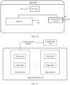
- An embodiment of a control node in embodiments of this application may include one or more processors 701, a memory 702, and a communications interface 703.
- the memory 702 may perform transitory storage or persistent storage. Further, the processor 701 may be configured to communicate with the memory 702, and perform, on the control device, a series of instruction operations in the memory 702.
- the processor 701 may perform the operations performed by the control node in the embodiment shown in FIG. 11 . Details are not described herein again.
- specific functional module division in the processor 701 may be similar to functional module division into modules such as the scheduling module, the sending module, and the image deployment module described in FIG. 11 , and details are not described herein again.
- An embodiment of an edge node in embodiments of this application may include one or more processors 801, a memory 802, and a communications interface 803.
- the memory 802 may perform transitory storage or persistent storage. Further, the processor 801 may be configured to communicate with the memory 802, and perform, on the control device, a series of instruction operations in the memory 802.
- the processor 801 may perform the operations performed by the edge node in the embodiment shown in FIG. 12 . Details are not described herein again.
- specific functional module division in the processor 801 may be similar to functional module division into modules such as the scheduling module, the detection module, the image obtaining module, and the image running module described in FIG. 12 , and details are not described herein again.
- FIG. 15 is a schematic diagram of an embodiment of an edge computing system according to an embodiment of this application. As shown in FIG. 15 , embodiments of this application further provide the edge computing system, including a control node 100 and an edge node cluster 200.
- a plurality of edge nodes included in the edge node cluster 200 are divided into N edge node sets, each edge node set includes at least two edge nodes, a first edge node set in the N edge node sets includes a second edge node, the second edge node stores a control rule, and N is a positive integer.
- the control node 100 is configured to perform the method for controlling the edge node according to any one of the first aspect or the possible implementations of the first aspect.
- the second edge node is configured to perform the method for controlling the edge node according to any one of the second aspect or the possible implementations of the second aspect.
- An embodiment of this application further provides a chip or a chip system.
- the chip or the chip system includes at least one processor and a communications interface.
- the communications interface is interconnected to the at least one processor through a line.
- the at least one processor is configured to run computer programs or instructions, to perform the operations performed by the control node in embodiments shown in FIG. 2 and FIG. 7 . Details are not described herein again.
- the communications interface in the chip may be an input/output interface, a pin, a circuit, or the like.
- Embodiments of this application further provide a first implementation of the chip or the chip system.
- the chip or the chip system described above in this application further includes at least one memory, and the at least one memory stores instructions.
- the memory may be a storage unit inside the chip, for example, a register or a cache, or may be a storage unit (for example, a read-only memory or a random access memory) of the chip.
- An embodiment of this application further provides a chip or a chip system.
- the chip or the chip system includes at least one processor and a communications interface.
- the communications interface is interconnected to the at least one processor through a line.
- the at least one processor is configured to run computer programs or instructions, to perform the operations performed by the edge node in embodiments shown in FIG. 8 and FIG. 9 . Details are not described herein again.
- the communications interface in the chip may be an input/output interface, a pin, a circuit, or the like.
- Embodiments of this application further provide a first implementation of the chip or the chip system.
- the chip or the chip system described above in this application further includes at least one memory, and the at least one memory stores instructions.
- the memory may be a storage unit inside the chip, for example, a register or a cache, or may be a storage unit (for example, a read-only memory or a random access memory) of the chip.
- An embodiment of this application further provides a computer storage medium.
- the computer storage medium is configured to store computer software instructions used by the foregoing control node or edge node, and the computer software instructions include a program designed for the control node or edge node.
- the control node may be the control node described in FIG. 11 .
- the edge node may be the edge node described in FIG. 12 .
- An embodiment of this application further provides a computer program product.
- the computer program product includes computer software instructions.
- the computer software instructions may be loaded by using a processor to implement procedures of the methods in FIG. 2 , FIG. 7 to FIG. 9 .
- All or some of foregoing embodiments may be implemented by using software, hardware, firmware, or any combination thereof.
- software is used to implement the foregoing embodiments, all or some of the foregoing embodiments may be implemented in a form of a computer program product.
- the disclosed system, apparatus and method may be implemented in other manners.
- the foregoing apparatus embodiments are merely examples.
- division into the units is merely logical function division and may be other division during actual implementation.
- a plurality of units or components may be combined or integrated into another system, or some features may be ignored or not performed.
- the displayed or discussed mutual couplings or direct couplings or communication connections may be implemented through some interfaces.
- the indirect couplings or communication connections between the apparatuses or units may be implemented in an electrical form, a mechanical form, or another form.
- the units described as separate parts may or may not be physically separate, and parts displayed as units may or may not be physical units, that is, they may be located in one position, or may be distributed on a plurality of network units. Some or all of the units may be selected according to actual requirements to achieve the objective of the solutions of embodiments.
- function units in embodiments of this application may be integrated into one processing unit, each of the units may exist alone physically, or two or more units are integrated into one unit.
- the integrated unit may be implemented in a form of hardware, or may be implemented in a form of a software function unit.
- the integrated unit When the integrated unit is implemented in the form of a software functional unit and sold or used as an independent product, the integrated unit may be stored in a computer-readable storage medium. Based on such an understanding, the technical solutions of this application essentially, or the part contributing to the conventional technology, or all or some of the technical solutions may be implemented in a form of a software product.
- the computer software product is stored in a storage medium and includes several instructions for instructing a computer device (which may be a personal computer, a server, or a network device) to perform all or some of the steps of the methods described in embodiments of this application.
- the foregoing storage medium includes: any medium that can store program code, such as a USB flash drive, a removable hard disk, a read-only memory (ROM, Read-Only Memory), a random access memory (RAM, Random Access Memory), a magnetic disk, or an optical disc.
- program code such as a USB flash drive, a removable hard disk, a read-only memory (ROM, Read-Only Memory), a random access memory (RAM, Random Access Memory), a magnetic disk, or an optical disc.
Landscapes
- Engineering & Computer Science (AREA)
- Computer Networks & Wireless Communication (AREA)
- Signal Processing (AREA)
- Environmental & Geological Engineering (AREA)
- Image Analysis (AREA)
- Information Retrieval, Db Structures And Fs Structures Therefor (AREA)
- Information Transfer Between Computers (AREA)
Claims (11)
- Procédé de commande d'un noeud d'extrémité, comprenant :la division (101), par un noeud de commande, d'une pluralité de noeuds d'extrémité compris dans une grappe de noeuds d'extrémité en N ensembles de noeuds d'extrémité, dans lequel chaque ensemble de noeuds d'extrémité comprend au moins deux noeuds d'extrémité, et N étant un nombre entier positif ;la sélection (102), par le noeud de commande, de M seconds noeuds d'extrémité à partir d'un premier ensemble de noeuds d'extrémité, dans lequel le premier ensemble de noeuds d'extrémité est l'un des N ensembles de noeuds d'extrémité, et M est un nombre entier positif ; etl'envoi (103), par le noeud de commande, d'une règle de commande aux M seconds noeuds d'extrémité, dans lequel la règle de commande indique au second noeud d'extrémité d'effectuer une détection de défaut sur un premier noeud d'extrémité, et le premier noeud d'extrémité appartient au premier ensemble de noeuds d'extrémité,caractérisé en ce qu'il comprendla division, par un noeud de commande, d'une pluralité de noeuds d'extrémité compris dans une grappe de noeuds d'extrémité en N ensembles de noeuds d'extrémité comprend :la sélection, par le noeud de commande, sur la base d'une image d'application à déployer et d'une image d'application qui a été déployée sur la pluralité de noeuds d'extrémité compris dans la grappe de noeuds d'extrémité, de K noeuds d'extrémité parmi la pluralité de noeuds d'extrémité pour former le premier ensemble de noeuds d'extrémité, dans lequel K est un nombre entier positif supérieur à M ; etl'activation, par le noeud de commande, des K noeuds d'extrémité pour former un anneau de hachage.
- Procédé selon la revendication 1,
dans lequel le premier noeud d'extrémité et au moins un second noeud d'extrémité sont adjacents dans l'anneau de hachage. - Procédé selon la revendication 1 ou 2, dans lequel après la division, par un noeud de commande, d'une pluralité de noeuds d'extrémité compris dans une grappe de noeuds d'extrémité en N ensembles de noeuds d'extrémité, le procédé comprend en outre :
le déploiement, par le noeud de commande, de X images en couches comprises dans l'image d'application à déployer sur L noeuds d'extrémité dans le premier ensemble de noeuds d'extrémité, dans lequel au moins une image en couches est déployée sur chacun des L noeuds d'extrémité, et L et X sont tous deux des nombres entiers positifs supérieurs à 1. - Procédé selon la revendication 3, dans lequel après le déploiement, par le noeud de commande, des X images en couches comprises dans l'image d'application à déployer sur L noeuds d'extrémité dans le premier ensemble de noeuds d'extrémité, le procédé comprend en outre :
l'envoi, par le noeud de commande, d'informations de déploiement de l'image d'application à déployer aux noeuds d'extrémité du premier ensemble de noeuds d'extrémité, dans lequel les informations de déploiement de l'image d'application comprend le déploiement de l'image en couches dans l'image d'application à déployer sur chacun des L noeuds d'extrémité. - Procédé de commande d'un noeud d'extrémité, appliqué à une grappe de noeuds d'extrémité,dans lequel une pluralité de noeuds d'extrémité compris dans la grappe de noeuds d'extrémité sont divisés (101), par un noeud de commande, en N ensembles de noeuds d'extrémité, chaque ensemble de noeuds d'extrémité comprend au moins deux noeuds d'extrémité, dans lequel N est un nombre entier positif,M seconds noeuds d'extrémité d'un premier ensemble de noeuds d'extrémité sont sélectionnés (102) par le noeud de commande, dans lequel le premier ensemble de noeuds d'extrémité est l'un des N ensembles de noeuds d'extrémité, et M est un nombre entier positif,la réception par les M seconds noeuds d'extrémité d'une règle de commande envoyée (103) par le noeud de commande, dans lequel la règle de commande indique qu'un second noeud d'extrémité doit effectuer une détection de défaillance sur un premier noeud d'extrémité, et que le premier et le second noeuds d'extrémité appartiennent au premier ensemble de noeuds d'extrémité,dans lequel la division, par un noeud de commande, d'une pluralité de noeuds d'extrémité compris dans une grappe de noeuds d'extrémité en N ensembles de noeuds d'extrémité comprend :la sélection, par le noeud de commande, sur la base d'une image d'application à déployer et d'une image d'application qui a été déployée sur la pluralité de noeuds d'extrémité compris dans la grappe de noeuds d'extrémité, de K noeuds d'extrémité parmi la pluralité de noeuds d'extrémité pour former le premier ensemble de noeuds d'extrémité, dans lequel K est un nombre entier positif supérieur à M ; etl'activation, par le noeud de commande, des K noeuds d'extrémité pour former un anneau de hachage ; etle procédé comprend :la détermination, par le second noeud d'extrémité, d'un premier noeud d'extrémité à partir du premier ensemble de noeuds d'extrémité conformément à la règle de commande ; etla réalisation, par le second noeud d'extrémité, d'une détection de défaillance sur le premier noeud d'extrémité.
- Procédé selon la revendication 5, dans lequel
le premier noeud d'extrémité et le second noeud d'extrémité sont adjacents dans l'anneau de hachage. - Procédé selon la revendication 5 ou 6, dans lequel au moins une des X images en couches comprises dans une image d'application est déployée sur chacun des L noeuds d'extrémité du premier ensemble de noeuds d'extrémité, et L et X sont tous deux des nombres entiers positifs supérieurs à 1 ;
chaque noeud d'extrémité du premier ensemble de noeuds d'extrémité stocke les informations de déploiement de l'image d'application, et les informations de déploiement de l'image d'application comprennent le déploiement de l'image en couches dans l'image d'application déployée sur chacun des L noeuds d'extrémité ; et le procédé comprend en outre :si H images en couches sont déployées sur le second noeud d'extrémité, l'obtention, par le second noeud d'extrémité, (X-H) images en couches d'un autre noeud d'extrémité dans les L noeuds d'extrémité sur la base des informations de déploiement de l'image d'application, pour former l'image d'application, dans lequel H est un nombre entier positif et X est un nombre entier positif supérieur à H ; etl'exécution, par le second noeud d'extrémité, de l'image d'application afin d'exécuter une tâche correspondante. - Procédé selon la revendication 7, dans lequel le procédé comprend en outre :si le premier noeud d'extrémité est défectueux, la détermination, par le second noeud d'extrémité sur la base des informations de déploiement de l'image d'application, le déploiement d'une image en couches dans l'image d'application déployée sur le premier noeud d'extrémité ; etsi au moins une image en couches est déployée sur le premier noeud d'extrémité, la sélection, par le second noeud d'extrémité, d'un noeud d'extrémité du premier ensemble de noeuds d'extrémité pour exécuter une tâche du premier noeud d'extrémité.
- Procédé selon la revendication 8, dans lequel, après la sélection, par le second noeud d'extrémité, d'un noeud d'extrémité du premier noeud d'extrémité destiné à exécuter une tâche du premier noeud d'extrémité, le procédé comprend en outre :si le second noeud d'extrémité est sélectionné pour exécuter la tâche du premier noeud d'extrémité et qu'aucune image en couches n'est déployée sur le second noeud d'extrémité, l'obtention, par le second noeud d'extrémité, des X images en couches des L noeuds d'extrémité sur la base des informations de déploiement de l'image d'application pour former l'image d'application ; etl'exécution, par le second noeud d'extrémité, de l'image d'application pour exécuter la tâche du premier noeud d'extrémité.
- Noeud de commande, comprenant au moins un processeur (701) et une mémoire (702), dans lequel la mémoire stocke des instructions exécutables par ordinateur qui peuvent être exécutées sur le processeur, et lorsque les instructions exécutables par ordinateur sont exécutées par le processeur, le noeud de commande effectue le procédé selon l'une des revendications 1 à 4.
- Support de stockage lisible par ordinateur, stockant une ou plusieurs instructions exécutables par ordinateur, dans lequel, lorsque la ou les instructions exécutables par ordinateur sont exécutées par un processeur, le processeur effectue le procédé selon l'une quelconque des revendications 1 à 9.
Applications Claiming Priority (2)
| Application Number | Priority Date | Filing Date | Title |
|---|---|---|---|
| CN201911425840.1A CN113132176B (zh) | 2019-12-31 | 2019-12-31 | 一种控制边缘节点的方法、节点及边缘计算系统 |
| PCT/CN2020/141209 WO2021136335A1 (fr) | 2019-12-31 | 2020-12-30 | Procédé de commande de nœud d'extrémité, nœud, et système de calcul d'extrémité |
Publications (3)
| Publication Number | Publication Date |
|---|---|
| EP4068717A1 EP4068717A1 (fr) | 2022-10-05 |
| EP4068717A4 EP4068717A4 (fr) | 2022-11-23 |
| EP4068717B1 true EP4068717B1 (fr) | 2025-02-12 |
Family
ID=76686547
Family Applications (1)
| Application Number | Title | Priority Date | Filing Date |
|---|---|---|---|
| EP20910742.4A Active EP4068717B1 (fr) | 2019-12-31 | 2020-12-30 | Procédé de commande de noeud d'extrémité, noeud, et système de calcul d'extrémité |
Country Status (4)
| Country | Link |
|---|---|
| US (1) | US12284242B2 (fr) |
| EP (1) | EP4068717B1 (fr) |
| CN (1) | CN113132176B (fr) |
| WO (1) | WO2021136335A1 (fr) |
Families Citing this family (10)
| Publication number | Priority date | Publication date | Assignee | Title |
|---|---|---|---|---|
| CN112910981B (zh) * | 2021-01-27 | 2022-07-26 | 联想(北京)有限公司 | 一种控制方法及装置 |
| CN115079935B (zh) * | 2021-03-15 | 2025-09-05 | 伊姆西Ip控股有限责任公司 | 用于存储和查询数据的方法、电子设备和计算机程序产品 |
| US20230030168A1 (en) * | 2021-07-27 | 2023-02-02 | Dell Products L.P. | Protection of i/o paths against network partitioning and component failures in nvme-of environments |
| CN115695419A (zh) * | 2021-07-27 | 2023-02-03 | 华为技术有限公司 | 通信系统、方法及装置 |
| CN116800590A (zh) * | 2022-06-29 | 2023-09-22 | 中移(苏州)软件技术有限公司 | 故障迁移方法、装置、电子设备和计算机存储介质 |
| US12321390B2 (en) | 2022-10-26 | 2025-06-03 | Dell Products L.P. | So-map: a semantic-aware algorithm for optimizing the representation structure of Octomaps |
| US12372374B2 (en) | 2022-10-27 | 2025-07-29 | Dell Products L.P. | Orchestration of action-input representations for decision making in edge environments |
| US20250094410A1 (en) * | 2023-09-14 | 2025-03-20 | Dell Products L.P. | Maximizing information gain of the joint environment knowledge at crowded edge applications |
| US12231500B1 (en) * | 2023-10-24 | 2025-02-18 | Dell Products L.P. | Exploiting structure in environment sensor dynamics for real-time maximization of information gain |
| CN120602495B (zh) * | 2025-08-08 | 2025-10-03 | 济南浪潮数据技术有限公司 | 边缘节点的状态确定方法、装置、电子设备和存储介质 |
Family Cites Families (19)
| Publication number | Priority date | Publication date | Assignee | Title |
|---|---|---|---|---|
| US7889655B2 (en) * | 2006-01-17 | 2011-02-15 | Cisco Technology, Inc. | Techniques for detecting loop-free paths that cross routing information boundaries |
| CN102855294B (zh) | 2012-08-13 | 2016-12-21 | 北京联创信安科技股份有限公司 | 一种智能哈希数据布局方法、集群存储系统及其方法 |
| US9173117B2 (en) * | 2013-05-02 | 2015-10-27 | Telefonaktiebolaget L M Ericsson (Publ) | Enhancing a mobile backup channel to address a node failure in a wireline network |
| CN105282045B (zh) | 2015-11-17 | 2018-11-16 | 高新兴科技集团股份有限公司 | 一种基于一致性哈希算法的分布式计算和储存方法 |
| WO2017176431A1 (fr) * | 2016-04-05 | 2017-10-12 | Wellaware Holdings, Inc. | Dispositif de surveillance et de commande d'un équipement industriel |
| US10333849B2 (en) * | 2016-04-28 | 2019-06-25 | Nicira, Inc. | Automatic configuration of logical routers on edge nodes |
| US10454758B2 (en) * | 2016-08-31 | 2019-10-22 | Nicira, Inc. | Edge node cluster network redundancy and fast convergence using an underlay anycast VTEP IP |
| CN107872823B (zh) * | 2016-09-28 | 2020-11-13 | 维布络有限公司 | 识别移动边缘计算环境中通信操作模式的方法和系统 |
| US10657061B1 (en) * | 2017-09-29 | 2020-05-19 | Amazon Technologies, Inc. | Resource distribution using attributes of versioned hash rings |
| CN108521461B (zh) * | 2018-04-04 | 2020-12-01 | 平安科技(深圳)有限公司 | 基于边缘计算的健康监测方法、装置、设备及存储介质 |
| US11836576B2 (en) * | 2018-04-13 | 2023-12-05 | International Business Machines Corporation | Distributed machine learning at edge nodes |
| CN108769214B (zh) * | 2018-05-31 | 2020-02-14 | 北京百度网讯科技有限公司 | 用于控制边缘计算设备、用于更新数据的方法和装置 |
| CN109491790B (zh) * | 2018-11-02 | 2021-08-27 | 中山大学 | 基于容器的工业物联网边缘计算资源分配方法及系统 |
| US20190097900A1 (en) * | 2018-11-26 | 2019-03-28 | Bryan J. Rodriguez | Zero-configuration cluster and provisioning pipeline for heterogeneous computing nodes |
| US10715391B2 (en) * | 2018-12-03 | 2020-07-14 | At&T Intellectual Property I, L.P. | Cloud zone network analytics platform |
| US11711268B2 (en) * | 2019-04-30 | 2023-07-25 | Intel Corporation | Methods and apparatus to execute a workload in an edge environment |
| CN110430069A (zh) * | 2019-07-09 | 2019-11-08 | 北京资信物联科技有限公司 | 低功耗物联网分层计算系统 |
| CN110399225A (zh) * | 2019-07-29 | 2019-11-01 | 中国工商银行股份有限公司 | 监测信息处理方法、系统和计算机系统 |
| CN110581782B (zh) * | 2019-09-17 | 2022-07-12 | 中国联合网络通信集团有限公司 | 一种容灾数据的处理方法、装置及系统 |
-
2019
- 2019-12-31 CN CN201911425840.1A patent/CN113132176B/zh active Active
-
2020
- 2020-12-30 WO PCT/CN2020/141209 patent/WO2021136335A1/fr not_active Ceased
- 2020-12-30 EP EP20910742.4A patent/EP4068717B1/fr active Active
-
2022
- 2022-06-29 US US17/852,724 patent/US12284242B2/en active Active
Also Published As
| Publication number | Publication date |
|---|---|
| US12284242B2 (en) | 2025-04-22 |
| US20220329650A1 (en) | 2022-10-13 |
| EP4068717A4 (fr) | 2022-11-23 |
| WO2021136335A1 (fr) | 2021-07-08 |
| EP4068717A1 (fr) | 2022-10-05 |
| CN113132176A (zh) | 2021-07-16 |
| CN113132176B (zh) | 2024-02-02 |
Similar Documents
| Publication | Publication Date | Title |
|---|---|---|
| EP4068717B1 (fr) | Procédé de commande de noeud d'extrémité, noeud, et système de calcul d'extrémité | |
| EP3402163B1 (fr) | Procédé et dispositif de gestion de ressources dans une plateforme en nuage | |
| EP3163797B1 (fr) | Procédé et appareil d'orchestration de service dans une mise en réseau définie par logiciel, et support de stockage | |
| CN109151045B (zh) | 一种分布式云系统及监控方法 | |
| US11102284B2 (en) | Service processing methods and systems based on a consortium blockchain network | |
| US20180048522A1 (en) | Instance node management method and management device | |
| EP3451727B1 (fr) | Procédé et dispositif de planification d'accès pour terminal, et support de stockage informatique | |
| EP3319270B1 (fr) | Procédé d'enregistrement de service, procédé d'utilisation et appareil correspondant | |
| CN105573996A (zh) | 数据库处理方法、装置及系统 | |
| CN110569124A (zh) | 一种任务分配方法和装置 | |
| CN114710485A (zh) | 处理方法和处理装置 | |
| CN117221326A (zh) | 软件负载均衡调度方法、系统、电子设备和存储介质 | |
| US11099965B2 (en) | Management system, test method and recording medium | |
| CN113535402A (zh) | 基于5g mec的负载均衡处理方法、装置及电子设备 | |
| CN118170513A (zh) | 基于云存储的应用迁移方法、装置、设备以及存储介质 | |
| CN114867119B (zh) | 一种资源调度方法、装置及存储介质 | |
| CN117807272A (zh) | 自适应的数据流转方法、系统、设备以及存储介质 | |
| CN116339758A (zh) | 软件部署方法、装置、设备及存储介质 | |
| CN111064636B (zh) | 前置机连接的控制方法、装置、系统、计算机设备 | |
| US20230251887A1 (en) | Data migration system, data migration method, non-transitory computer-readable medium for data migration program | |
| CN114138406A (zh) | 一种应用容器快速部署平台 | |
| CN112685613A (zh) | 一种资源包查询的方法、装置及信息处理系统 | |
| CN112822792A (zh) | 承载标识的分配方法、装置、设备和存储介质 | |
| CN117806815B (zh) | 数据处理方法、系统、电子设备及存储介质 | |
| JP6921795B2 (ja) | 移動通信ネットワーク及び管理装置 |
Legal Events
| Date | Code | Title | Description |
|---|---|---|---|
| STAA | Information on the status of an ep patent application or granted ep patent |
Free format text: STATUS: THE INTERNATIONAL PUBLICATION HAS BEEN MADE |
|
| PUAI | Public reference made under article 153(3) epc to a published international application that has entered the european phase |
Free format text: ORIGINAL CODE: 0009012 |
|
| STAA | Information on the status of an ep patent application or granted ep patent |
Free format text: STATUS: REQUEST FOR EXAMINATION WAS MADE |
|
| 17P | Request for examination filed |
Effective date: 20220701 |
|
| AK | Designated contracting states |
Kind code of ref document: A1 Designated state(s): AL AT BE BG CH CY CZ DE DK EE ES FI FR GB GR HR HU IE IS IT LI LT LU LV MC MK MT NL NO PL PT RO RS SE SI SK SM TR |
|
| REG | Reference to a national code |
Ref country code: DE Ref legal event code: R079 Free format text: PREVIOUS MAIN CLASS: H04L0029060000 Ipc: H04L0065400000 Ref country code: DE Ref legal event code: R079 Ref document number: 602020046142 Country of ref document: DE Free format text: PREVIOUS MAIN CLASS: H04L0029060000 Ipc: H04L0065400000 |
|
| A4 | Supplementary search report drawn up and despatched |
Effective date: 20221021 |
|
| RIC1 | Information provided on ipc code assigned before grant |
Ipc: H04L 65/40 20220101AFI20221017BHEP |
|
| DAV | Request for validation of the european patent (deleted) | ||
| DAX | Request for extension of the european patent (deleted) | ||
| STAA | Information on the status of an ep patent application or granted ep patent |
Free format text: STATUS: EXAMINATION IS IN PROGRESS |
|
| 17Q | First examination report despatched |
Effective date: 20230811 |
|
| GRAP | Despatch of communication of intention to grant a patent |
Free format text: ORIGINAL CODE: EPIDOSNIGR1 |
|
| STAA | Information on the status of an ep patent application or granted ep patent |
Free format text: STATUS: GRANT OF PATENT IS INTENDED |
|
| INTG | Intention to grant announced |
Effective date: 20240927 |
|
| GRAS | Grant fee paid |
Free format text: ORIGINAL CODE: EPIDOSNIGR3 |
|
| GRAA | (expected) grant |
Free format text: ORIGINAL CODE: 0009210 |
|
| STAA | Information on the status of an ep patent application or granted ep patent |
Free format text: STATUS: THE PATENT HAS BEEN GRANTED |
|
| AK | Designated contracting states |
Kind code of ref document: B1 Designated state(s): AL AT BE BG CH CY CZ DE DK EE ES FI FR GB GR HR HU IE IS IT LI LT LU LV MC MK MT NL NO PL PT RO RS SE SI SK SM TR |
|
| P01 | Opt-out of the competence of the unified patent court (upc) registered |
Free format text: CASE NUMBER: APP_742/2025 Effective date: 20250108 |
|
| REG | Reference to a national code |
Ref country code: GB Ref legal event code: FG4D |
|
| REG | Reference to a national code |
Ref country code: CH Ref legal event code: EP |
|
| REG | Reference to a national code |
Ref country code: DE Ref legal event code: R096 Ref document number: 602020046142 Country of ref document: DE |
|
| REG | Reference to a national code |
Ref country code: IE Ref legal event code: FG4D |
|
| REG | Reference to a national code |
Ref country code: NL Ref legal event code: MP Effective date: 20250212 |
|
| PG25 | Lapsed in a contracting state [announced via postgrant information from national office to epo] |
Ref country code: RS Free format text: LAPSE BECAUSE OF FAILURE TO SUBMIT A TRANSLATION OF THE DESCRIPTION OR TO PAY THE FEE WITHIN THE PRESCRIBED TIME-LIMIT Effective date: 20250512 |
|
| PG25 | Lapsed in a contracting state [announced via postgrant information from national office to epo] |
Ref country code: FI Free format text: LAPSE BECAUSE OF FAILURE TO SUBMIT A TRANSLATION OF THE DESCRIPTION OR TO PAY THE FEE WITHIN THE PRESCRIBED TIME-LIMIT Effective date: 20250212 |
|
| PG25 | Lapsed in a contracting state [announced via postgrant information from national office to epo] |
Ref country code: PL Free format text: LAPSE BECAUSE OF FAILURE TO SUBMIT A TRANSLATION OF THE DESCRIPTION OR TO PAY THE FEE WITHIN THE PRESCRIBED TIME-LIMIT Effective date: 20250212 |
|
| PG25 | Lapsed in a contracting state [announced via postgrant information from national office to epo] |
Ref country code: ES Free format text: LAPSE BECAUSE OF FAILURE TO SUBMIT A TRANSLATION OF THE DESCRIPTION OR TO PAY THE FEE WITHIN THE PRESCRIBED TIME-LIMIT Effective date: 20250212 |
|
| REG | Reference to a national code |
Ref country code: LT Ref legal event code: MG9D |
|
| PG25 | Lapsed in a contracting state [announced via postgrant information from national office to epo] |
Ref country code: NO Free format text: LAPSE BECAUSE OF FAILURE TO SUBMIT A TRANSLATION OF THE DESCRIPTION OR TO PAY THE FEE WITHIN THE PRESCRIBED TIME-LIMIT Effective date: 20250512 Ref country code: IS Free format text: LAPSE BECAUSE OF FAILURE TO SUBMIT A TRANSLATION OF THE DESCRIPTION OR TO PAY THE FEE WITHIN THE PRESCRIBED TIME-LIMIT Effective date: 20250612 |
|
| PG25 | Lapsed in a contracting state [announced via postgrant information from national office to epo] |
Ref country code: NL Free format text: LAPSE BECAUSE OF FAILURE TO SUBMIT A TRANSLATION OF THE DESCRIPTION OR TO PAY THE FEE WITHIN THE PRESCRIBED TIME-LIMIT Effective date: 20250212 |
|
| PG25 | Lapsed in a contracting state [announced via postgrant information from national office to epo] |
Ref country code: HR Free format text: LAPSE BECAUSE OF FAILURE TO SUBMIT A TRANSLATION OF THE DESCRIPTION OR TO PAY THE FEE WITHIN THE PRESCRIBED TIME-LIMIT Effective date: 20250212 |
|
| PG25 | Lapsed in a contracting state [announced via postgrant information from national office to epo] |
Ref country code: PT Free format text: LAPSE BECAUSE OF FAILURE TO SUBMIT A TRANSLATION OF THE DESCRIPTION OR TO PAY THE FEE WITHIN THE PRESCRIBED TIME-LIMIT Effective date: 20250612 Ref country code: LV Free format text: LAPSE BECAUSE OF FAILURE TO SUBMIT A TRANSLATION OF THE DESCRIPTION OR TO PAY THE FEE WITHIN THE PRESCRIBED TIME-LIMIT Effective date: 20250212 |
|
| PG25 | Lapsed in a contracting state [announced via postgrant information from national office to epo] |
Ref country code: GR Free format text: LAPSE BECAUSE OF FAILURE TO SUBMIT A TRANSLATION OF THE DESCRIPTION OR TO PAY THE FEE WITHIN THE PRESCRIBED TIME-LIMIT Effective date: 20250513 Ref country code: BG Free format text: LAPSE BECAUSE OF FAILURE TO SUBMIT A TRANSLATION OF THE DESCRIPTION OR TO PAY THE FEE WITHIN THE PRESCRIBED TIME-LIMIT Effective date: 20250212 |
|
| REG | Reference to a national code |
Ref country code: AT Ref legal event code: MK05 Ref document number: 1767178 Country of ref document: AT Kind code of ref document: T Effective date: 20250212 |
|
| PG25 | Lapsed in a contracting state [announced via postgrant information from national office to epo] |
Ref country code: SE Free format text: LAPSE BECAUSE OF FAILURE TO SUBMIT A TRANSLATION OF THE DESCRIPTION OR TO PAY THE FEE WITHIN THE PRESCRIBED TIME-LIMIT Effective date: 20250212 |
|
| PG25 | Lapsed in a contracting state [announced via postgrant information from national office to epo] |
Ref country code: SM Free format text: LAPSE BECAUSE OF FAILURE TO SUBMIT A TRANSLATION OF THE DESCRIPTION OR TO PAY THE FEE WITHIN THE PRESCRIBED TIME-LIMIT Effective date: 20250212 |
|
| PG25 | Lapsed in a contracting state [announced via postgrant information from national office to epo] |
Ref country code: DK Free format text: LAPSE BECAUSE OF FAILURE TO SUBMIT A TRANSLATION OF THE DESCRIPTION OR TO PAY THE FEE WITHIN THE PRESCRIBED TIME-LIMIT Effective date: 20250212 |
|
| PG25 | Lapsed in a contracting state [announced via postgrant information from national office to epo] |
Ref country code: IT Free format text: LAPSE BECAUSE OF FAILURE TO SUBMIT A TRANSLATION OF THE DESCRIPTION OR TO PAY THE FEE WITHIN THE PRESCRIBED TIME-LIMIT Effective date: 20250212 |
|
| PG25 | Lapsed in a contracting state [announced via postgrant information from national office to epo] |
Ref country code: AT Free format text: LAPSE BECAUSE OF FAILURE TO SUBMIT A TRANSLATION OF THE DESCRIPTION OR TO PAY THE FEE WITHIN THE PRESCRIBED TIME-LIMIT Effective date: 20250212 |
|
| PG25 | Lapsed in a contracting state [announced via postgrant information from national office to epo] |
Ref country code: CZ Free format text: LAPSE BECAUSE OF FAILURE TO SUBMIT A TRANSLATION OF THE DESCRIPTION OR TO PAY THE FEE WITHIN THE PRESCRIBED TIME-LIMIT Effective date: 20250212 Ref country code: EE Free format text: LAPSE BECAUSE OF FAILURE TO SUBMIT A TRANSLATION OF THE DESCRIPTION OR TO PAY THE FEE WITHIN THE PRESCRIBED TIME-LIMIT Effective date: 20250212 |
|
| PG25 | Lapsed in a contracting state [announced via postgrant information from national office to epo] |
Ref country code: RO Free format text: LAPSE BECAUSE OF FAILURE TO SUBMIT A TRANSLATION OF THE DESCRIPTION OR TO PAY THE FEE WITHIN THE PRESCRIBED TIME-LIMIT Effective date: 20250212 |
|
| PG25 | Lapsed in a contracting state [announced via postgrant information from national office to epo] |
Ref country code: SK Free format text: LAPSE BECAUSE OF FAILURE TO SUBMIT A TRANSLATION OF THE DESCRIPTION OR TO PAY THE FEE WITHIN THE PRESCRIBED TIME-LIMIT Effective date: 20250212 |
|
| REG | Reference to a national code |
Ref country code: DE Ref legal event code: R097 Ref document number: 602020046142 Country of ref document: DE |
|
| PLBE | No opposition filed within time limit |
Free format text: ORIGINAL CODE: 0009261 |
|
| STAA | Information on the status of an ep patent application or granted ep patent |
Free format text: STATUS: NO OPPOSITION FILED WITHIN TIME LIMIT |
|
| PGFP | Annual fee paid to national office [announced via postgrant information from national office to epo] |
Ref country code: DE Payment date: 20251104 Year of fee payment: 6 |
|
| PGFP | Annual fee paid to national office [announced via postgrant information from national office to epo] |
Ref country code: FR Payment date: 20251110 Year of fee payment: 6 |
|
| PGFP | Annual fee paid to national office [announced via postgrant information from national office to epo] |
Ref country code: IE Payment date: 20251111 Year of fee payment: 6 |
|
| 26N | No opposition filed |
Effective date: 20251113 |