EP4068737A1 - Mécanisme d'arbre rotatif pour écran pliable, ensemble écran pliable et terminal mobile pliable - Google Patents
Mécanisme d'arbre rotatif pour écran pliable, ensemble écran pliable et terminal mobile pliable Download PDFInfo
- Publication number
- EP4068737A1 EP4068737A1 EP19950231.1A EP19950231A EP4068737A1 EP 4068737 A1 EP4068737 A1 EP 4068737A1 EP 19950231 A EP19950231 A EP 19950231A EP 4068737 A1 EP4068737 A1 EP 4068737A1
- Authority
- EP
- European Patent Office
- Prior art keywords
- foldable
- mobile terminal
- foldable screen
- rotation shaft
- cam
- Prior art date
- Legal status (The legal status is an assumption and is not a legal conclusion. Google has not performed a legal analysis and makes no representation as to the accuracy of the status listed.)
- Granted
Links
Images




Classifications
-
- G—PHYSICS
- G06—COMPUTING OR CALCULATING; COUNTING
- G06F—ELECTRIC DIGITAL DATA PROCESSING
- G06F1/00—Details not covered by groups G06F3/00 - G06F13/00 and G06F21/00
- G06F1/16—Constructional details or arrangements
- G06F1/1613—Constructional details or arrangements for portable computers
- G06F1/1633—Constructional details or arrangements of portable computers not specific to the type of enclosures covered by groups G06F1/1615 - G06F1/1626
- G06F1/1637—Details related to the display arrangement, including those related to the mounting of the display in the housing
- G06F1/1652—Details related to the display arrangement, including those related to the mounting of the display in the housing the display being flexible, e.g. mimicking a sheet of paper, or rollable
-
- H—ELECTRICITY
- H04—ELECTRIC COMMUNICATION TECHNIQUE
- H04M—TELEPHONIC COMMUNICATION
- H04M1/00—Substation equipment, e.g. for use by subscribers
- H04M1/02—Constructional features of telephone sets
- H04M1/0202—Portable telephone sets, e.g. cordless phones, mobile phones or bar type handsets
- H04M1/026—Details of the structure or mounting of specific components
- H04M1/0266—Details of the structure or mounting of specific components for a display module assembly
- H04M1/0268—Details of the structure or mounting of specific components for a display module assembly including a flexible display panel
-
- G—PHYSICS
- G06—COMPUTING OR CALCULATING; COUNTING
- G06F—ELECTRIC DIGITAL DATA PROCESSING
- G06F1/00—Details not covered by groups G06F3/00 - G06F13/00 and G06F21/00
- G06F1/16—Constructional details or arrangements
- G06F1/1613—Constructional details or arrangements for portable computers
- G06F1/1633—Constructional details or arrangements of portable computers not specific to the type of enclosures covered by groups G06F1/1615 - G06F1/1626
- G06F1/1675—Miscellaneous details related to the relative movement between the different enclosures or enclosure parts
- G06F1/1681—Details related solely to hinges
-
- H—ELECTRICITY
- H04—ELECTRIC COMMUNICATION TECHNIQUE
- H04M—TELEPHONIC COMMUNICATION
- H04M1/00—Substation equipment, e.g. for use by subscribers
- H04M1/02—Constructional features of telephone sets
- H04M1/0202—Portable telephone sets, e.g. cordless phones, mobile phones or bar type handsets
- H04M1/0206—Portable telephones comprising a plurality of mechanically joined movable body parts, e.g. hinged housings
- H04M1/0208—Portable telephones comprising a plurality of mechanically joined movable body parts, e.g. hinged housings characterized by the relative motions of the body parts
- H04M1/0214—Foldable telephones, i.e. with body parts pivoting to an open position around an axis parallel to the plane they define in closed position
-
- H—ELECTRICITY
- H04—ELECTRIC COMMUNICATION TECHNIQUE
- H04M—TELEPHONIC COMMUNICATION
- H04M1/00—Substation equipment, e.g. for use by subscribers
- H04M1/02—Constructional features of telephone sets
- H04M1/0202—Portable telephone sets, e.g. cordless phones, mobile phones or bar type handsets
- H04M1/0206—Portable telephones comprising a plurality of mechanically joined movable body parts, e.g. hinged housings
- H04M1/0208—Portable telephones comprising a plurality of mechanically joined movable body parts, e.g. hinged housings characterized by the relative motions of the body parts
- H04M1/0214—Foldable telephones, i.e. with body parts pivoting to an open position around an axis parallel to the plane they define in closed position
- H04M1/0216—Foldable in one direction, i.e. using a one degree of freedom hinge
- H04M1/022—The hinge comprising two parallel pivoting axes
Definitions
- the present application relates to the technical field of foldable screen application design, and particularly to a rotation shaft mechanism for a foldable screen, a foldable screen assembly, and a foldable mobile terminal.
- the present application relates to the technical field of foldable screen application design, and particularly to a rotation shaft mechanism for a foldable screen, a foldable screen assembly, and a foldable mobile terminal.
- the present application provides a rotation shaft mechanism for a foldable screen, a foldable screen assembly, and a foldable mobile terminal which can reduce the possibility of screen wear at the bending and make the foldable screen of the foldable mobile terminal slide more smoothly, effectively solving the layering problem caused by foldable screen wrinkles, significantly improving the user experience, and completely solving many problems with technology in the current situation.
- the present application provides a rotation shaft mechanism for a foldable screen, comprising a left arm and a right arm that are symmetrically arranged, wherein: the left arm is configured to secure a left support of a foldable mobile terminal, and the right arm is configured to secure a right support of the foldable mobile terminal; one end of the left arm is fixed with a left rotation shaft and one end of the right arm is fixed with a right rotation shaft that is symmetrically arranged with the the left rotation shaft; the left rotation shaft is connected with a left cam, the right rotation shaft is connected with a right cam, the left cam and the right cam are both arranged on one side of first limiting plate, and a second limiting plate is arranged on the other side of the first limiting plate; a left gear, a right gear, and a transmission gear are arranged between the first limiting plate and the second limiting plate; one end of a central fixed shaft of the left gear penetrates into a first left limiting hole of the first limiting plate and is driving
- a left fan-shaped sliding slot is formed in an inner surface of the left arm, a left connecting rod is provided in the left fan-shaped sliding slot, a left central shaft is fixed to a circle center of the left fan-shaped sliding slot, the left central shaft is rotatably connected to one end of the left connecting rod, and the other end of the left connecting rod is rotatably connected to a left swing shaft, and the left swing shaft is rotatably connected to a left side of a left lifting plate of the foldable mobile terminal;
- a right fan-shaped sliding slot is formed in an inner surface of the right arm, a right connecting rod is provided in the right fan-shaped sliding slot, a right central shaft is fixed to a circle center of the right fan-shaped sliding slot, the right central shaft is rotatably connected to one end of the right connecting rod, the other end of the right connecting rod is rotatably connected with a right swing shaft, and the right swing shaft is rotatably connected with a right side of a right lifting plate of the foldable mobile terminal;
- an anchor block is provided at a middle of a bracket of the foldable mobile terminal, the second limiting plate is fixed to the anchor block, a left hinge and a right hinge are respectively fixed on both sides of the anchor block, a right side of the left lifting plateof the foldable mobile terminal is hinged to the anchor block through the left hinge, and a left side of the right lifting plate of the foldable mobile terminal is hinged to the anchor block through the right hinge; and a left containment hole corresponding to the second left limiting hole and a right containment hole corresponding to the second right limiting hole are formed on the anchor block, the other end of the central fixed shaft of the left gear sequentially penetrates the second left limiting hole and the left containment hole, the other end of the central fixed shaft of the right gear sequentially penetrates the second right limiting hole and the right containment hole.
- the left cam and the right cam are symmetrically arranged and have same structures, both comprising a first cam and a second cam that are secured to each other and arranged in an offset manner; and the two first cams are respectively connected to the left rotation shaft and the right rotation shaft; and the two second cams are respectively connected to the central fixed shaft of the left gear and the central fixed shaft of the right gear.
- the present application further provides a foldable screen assembly compising any rotation shaft mechanism for foldable screens disclosed above.
- the foldable screen assembly further comprises a slide rail mechanism comprising a steel sheet, a sliding part and a guide part, the sliding part is fixed on the steel sheet, the guide part is fixed on the bracket of the foldable mobile terminal, the sliding part cooperates with the guide part and slides along the guide part, and the steel sheet is configured to fix a foldable screen of the foldable mobile terminal.
- the sliding part is a bending piece extending from an edge of the steel sheet, and a strip hole is formed in the bending piece; and the guide part comprises a support block and a limiting member, the support block is fixed on the bracket of the foldable mobile terminal, the limiting member is fixed on a side of the support block, a rod portion of the limiting member passes through the strip hole and its end is secured to the support block, the strip hole is located between a head portion of the limiting member and the support block, and a diameter of the head portion of the limiting member is greater than a width of the strip hole.
- the foldable screen assembly further comprises a booster mechanism, and the booster mechanism comprises: a spring, and the spring is in a compressed state under an action of a pulling force of the foldable screen fixed on the steel sheet when the foldable screen of the foldable mobile terminal is in an unfolded state; and the spring releases a thrust that pushes the foldable screen to slide to both sides when the foldable screen of the foldable mobile terminal is restored to a folded state.
- the spring is a compression spring
- the compression spring is arranged in a cylindrical housing with one end closed, the cylindrical housing is fixed on the bracket of the foldable mobile terminal, the compression spring is connected to a head portion of the push rod in the cylindrical housing, an end of a rod part of the push rod protrudes from the cylindrical housing and abuts on the steel sheet, and a diameter of a head portion of the push rod is greater than a diameter of an opening of the cylindrical housing.
- the present application further provides a foldable mobile terminal comprising any foldable screen assembly disclosed above or any rotation shaft mechanism for foldable screens disclosed above.
- the foldable mobile terminals may be a portable electronic product with a foldable screen, such as a smart phone, a smart watch, a smart bracelet, a tablet computer, a notebook computer, or a smart wearable device (such as a smart helmet and smart glasses).
- a foldable screen such as a smart phone, a smart watch, a smart bracelet, a tablet computer, a notebook computer, or a smart wearable device (such as a smart helmet and smart glasses).
- the present application can hide the extra part of the foldable screen in the space formed by sinking of the lifting plate, which better prevents friction or resistance to the bending screen made by other structures (such as brackets, or componments of the rotating shaft).
- the present application provides a brand new screen sliding solution.
- the solution can better work with the foldable screen and ensure that the screen is unfolded or fully folded. In the process, it slides on the top of the case very smoothly without affecting the screen display effect at all, which can meet the folding needs of foldable mobile terminals in different forms, significantly improve the user experience, and better solve the existing foldable mobile terminals and problems such as proneness to jamming and unsmooth sliding.
- the present application has the outstanding advantages of simple structure, easy implementation, low cost, strong reliability, long life, and wide application range, and can be directly applied to foldable mobile terminals.
- location or position relationships indicated by terms such as “center”, “longitudinal”, “transverse”, “length”, “width”, “thickness”, “up”, “down”, “front”, “rear”, “left”, “right”, “vertical”, “horizontal”, “top”, “bottom”, “inside”, and “outside” are location or position relationships based on illustration of the accompanying drawings, are merely used for describing the present disclosure and simplifying the description instead of indicating or implying the indicated apparatuses or elements should have specified locations or be constructed and operated according to specified locations, and thereof, should not be intercepted as limitations to the present disclosure. Furthermore, structural elements with same or similar characteristics may be indicated by same or different reference numerals in the present disclosure.
- first and second are used merely for description, but shall not be construed as indicating or implying relative importance or implicitly indicating a number of the indicated technical feature. Hence, the feature defined with “first” and “second” may explicitly or implicitly includes one or more such features.
- a term “a plurality of' means “two or more” unless otherwise specifically limited.
- the terms “installed”, “connected”, “connected”, “fixed” and other terms should be understood in a broad sense, for example, it can be a fixed connection or a detachable connection , Or integrated; it can be mechanically connected or electrically connected; it can be directly connected or indirectly connected through an intermediary, it can be the internal communication of two components or the interaction relationship between two components, unless otherwise specified The limit.
- installed can be a fixed connection or a detachable connection , Or integrated; it can be mechanically connected or electrically connected; it can be directly connected or indirectly connected through an intermediary, it can be the internal communication of two components or the interaction relationship between two components, unless otherwise specified The limit.
- the specific meanings of the above-mentioned terms in the present application can be understood according to specific circumstances.
- the word "exemplary” is used to mean “serving as an example, illustration, or illustration.”. Any embodiment described as “exemplary” in the present application is not necessarily construed as being more preferred or advantageous over other embodiments.
- the present application lists details for the purpose of explanation. It should be understood that those of ordinary skill in the art can realize that the present application can be implemented even without using these specific details. In other instances, well-known structures and processes will not be elaborated in detail to prevent unnecessary details to obscure the description of the present application. Therefore, the present application is not intended to be limited to the illustrated embodiments, but should be consistent with the widest scope that conforms to the principles and features disclosed in the present application.
- FIG. 1 is an exploded structure diagram of an embodiment of a rotation shaft mechanism for a foldable screen provided in the present application.
- the foldable screen in the present application can be understood as a kind of flexible screen.
- the present embodiment provides a rotation shaft mechanism for a foldable screen.
- Both the top and bottom of a foldable mobile terminal can each be provided with a rotation shaft mechanism, and this two rotation shaft mechanisms need to move synchronously and be arranged symmetrically.
- a bracket 26 of the foldable mobile terminal comprises a left bracket of the foldable mobile terminal and a right bracket of the foldable mobile terminal.
- a steel sheet is arranged on the left bracket and a steel sheet is arranged on the right bracket.
- the foldable screen assembly may also comprise an improved rotation shaft mechanism, which can not only provide storage space for a folding position of a folded foldable screen and improve the bending performance of the foldable screen, but also can be used to better open or close the foldable screen, and make the screen unfolding or closing process smoother, Thereby improving user experience.
- the rotation shaft mechanism comprises a left arm 11 and a right arm 12 that are symmetrically arranged.
- the left arm 11 is configured to secure a left support of a foldable mobile terminal
- the right arm 12 is configured to secure a right support of the foldable mobile terminal
- one end of the left arm 11 is fixed with a left rotation shaft 13
- one end of the right arm 12 is fixed with a right rotation shaft 14 that is symmetrically arranged with the the left rotation shaft 13.
- the left rotation shaft 13 is secured to a left cam 15, and/or the right rotation shaft 14 is secured to a right cam 16.
- At least one rotation shaft is secured to one cam, and the other rotation shaft can be secured to or rotationally connected to ensure that these arms move synchronously during the process of unfolding or folding the foldable screen.
- the left cam 15 and the right cam 16 are both arranged on one side of a first limiting plate 17, and a second limiting plate 18 is arranged on the other side of the first limiting plate 17.
- a left gear 151, a right gear 152, and a transmission gear 153 are arranged between the first limiting plate 17 and the second limiting plate 18.
- One end of a central fixed shaft of the left gear 151 penetrates into a first left limiting hole of the first limiting plate 17 and is drivingly connected with the left cam 15, and the other end of the central fixed shaft of the left gear 151 penetrates into a second left limiting hole of the second limiting plate 18.
- One end of a central fixed shaft of the right gear 152 penetrates into a first right limiting hole of the first limiting plate 17 and is drivingly connected with the right cam 16, and the other end of the central fixed shaft of the right gear 152 penetrates into a second right limiting hole of the second limiting plate 18.
- At least one transmission gear 153 is is drivingly connected between the left gear 151 and the right gear 152.
- each shaft mechanism has two transmission gears, which are used to ensure that the four arms rotate synchronously when an user unfolds or folds the foldable screen, that is, after at least one arm drives the rotation shaft to move, the rotation shaft drives the cam to move, the cam drives the gear on one side, the gear on one side drives the transmission gear, and the arm on the other side can act as the active moving part under the drive of the bracket connected to it, or the power transmitted from the aforementioned arm on the other side.
- two ends of a central fixed shaft of the transmission gear 153 respectively penetrate into a first middle limiting hole of the first limiting plate 17 and a second middle limiting hole of the second limiting plate 18.
- two symmetrically arranged rotating shaft mechanisms are arranged on the bracket of the mobile terminal, specifically are shown at positions C1 and C2 in FIG. 4 .
- a left fan-shaped sliding slot is formed in an inner surface of the left arm 11, a left connecting rod 111 used to rotate according to unfolding or folding of the foldable screen is provided in the left fan-shaped sliding slot, a left central shaft 112 is fixed to a circle center of the left fan-shaped sliding slot, the left central shaft 112 is rotatably connected to one end of the left connecting rod 111, and the other end of the left connecting rod 111 is rotatably connected to a left swing shaft 113, and the left swing shaft 113 is rotatably connected to a left side of a left lifting plate 114 of the foldable mobile terminal. As shown in FIGs.
- a right fan-shaped sliding slot is formed in an inner surface of the right arm 12
- a right connecting rod 121 used to rotate according to unfolding or folding of the foldable screen is provided in the right fan-shaped sliding slot
- a right central shaft 122 is fixed to a circle center of the right fan-shaped sliding slot
- the right central shaft 122 is rotatably connected to one end of the right connecting rod 121
- the other end of the right connecting rod 121 is rotatably connected with a right swing shaft 123
- the right swing shaft 123 is rotatably connected with a right side of a right lifting plate 124 of the foldable mobile terminal.
- the left lifting and right lifting plates are both arranged on the back of the foldable screen.
- the left lifting plate 114 and the right lifting plate 124 can be raised and lowered along a direction perpendicular to the screen as the foldable screen is unfolded or folded. Specifically, the left lifting plate 114 and the right lifting plate 124 are far away from the foldable screen (that is, "upward") when the foldable screen is folded. The left lifting plate 114 and the right lifting plate 124 are close to the foldable screen (that is, "downward") when the foldable screen is unfolded so that sliding of the foldable screen is more smooth during unfolding or folding.
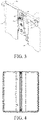
- FIG. 3 is a schematic diagram of the state of the left lifting plate 114 and the right lifting plate 124 when the foldable screen is unfolded.
- the left cam 15 and the right cam 16 of this embodiment are symmetrically arranged and have same structures, both comprising a first cam and a second cam that are secured to each other and arranged in an offset manner.
- the two first cams are respectively connected to the left rotation shaft 13 and the right rotation shaft 14, and the two second cams are respectively connected to the central fixed shaft of the left gear 151 and the central fixed shaft of the right gear 152.
- one end surface of the left arm 11 is fixed with a left rotation shaft 13 and the other end surface is fixed with a left support shaft corresponding to the left rotation shaft 13 but with a different axis.
- One end surface of the support arm 12 is fixed with the right rotation shaft 14 and the other end surface is fixed with a right support shaft corresponding to the right rotation shaft 14 but with a different axis.
- the left support shaft and the right support shaft (not marked) above the rotation shaft in the figures are both used to rotationally connect with the bracket.
- a crosssection of the foldable screen in a folded state can also be in a "wafer -drop" shape by setting the upper and lower shafts with different shaft centers.
- the left lifting plate 114 on the left half in FIG. 3 is connected with the left arm 11 and the right lifting plate 124 on the right half is not connected with the right arm 12.
- An anchor block 19 is provided at a middle of the bracket 26 of the foldable mobile terminal, the second limiting plate 18 is fixed to the anchor block 19, a left hinge and a right hinge are respectively fixed on both sides of the anchor block 19, a right side of the left lifting plate 114 of the foldable mobile terminal is hinged to the anchor block 19 through the left hinge, and a left side of the right lifting plate 124 of the foldable mobile terminal is hinged to the anchor block 19 through the right hinge.
- a left containment hole corresponding to the second left limiting hole and a right containment hole corresponding to the second right limiting hole are formed on the anchor block 19, the other end of the central fixed shaft of the left gear 151 sequentially penetrates the second left limiting hole and the left containment hole, the other end of the central fixed shaft of the right gear 152 sequentially penetrates the second right limiting hole and the right containment hole.
- the foldable screen assembly provided in the present application, through cooperation of the slide rail mechanism, the booster mechanism, and the rotating shaft mechanism, the screen is unfolded by 180° when a case of the foldable mobile terminal is opened.
- a surplus part of the foldable screen after being folded is hidden in the space formed by the movement of the hinge mechanism (that is, the space formed by the sinking of the lifting plate) when the foldable mobile terminal case is closed, which prevents friction or resistance of other structures (such as brackets, shaft-related parts, etc.) to the screen at the bending place, thereby improving the bending performance of the foldable screen, making the cross section of the foldable screen to be bent in a "water-drop" shape, which can better meet different folding demands (especially inward folding) of the current mobile phones with foldable screens.
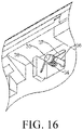
- the present application also provides a foldable screen assembly, as shown in FIGs. 1 to 16 .
- the foldable screen assembly comprises any one of the above embodiments of the rotation shaft mechanism for the foldable screens, and the foldable screen assembly also comprises a slide rail mechanism and a booster mechanism.
- the slide rail mechanism comprises a sliding part and a guide part 27, and is able to achieve a better sliding effect of the foldable screen.
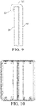
- the sliding part is a bending piece 21 extending from an edge of the steel sheet 25, and a strip hole 22 is formed in the bending piece 21.
- the guide part 27 comprises a support block 24 and a limiting member 23, the support block 24 is fixed on the bracket 26 (i.e. the case) of the foldable mobile terminal.
- the limiting member 23 is fixed on a side of the support block 24, and the limiting member 23 may be a screw-shape, which includes a head portion and a rod portion.
- the rod portion of the limiting member 23 passes through the strip hole 22 and its end is secured to the support block 24, the strip hole 22 is located between a head portion of the limiting member 23 and the support block 24, and a diameter of the head portion of the limiting member 23 is greater than a width of the strip hole 22.
- eight slide rail mechanisms can also be arranged to achieve a better screen sliding effect.
- the slide rail mechanism comprises a steel sheet 25, the sliding part, and the guide part 27, and the sliding part is fixed on the steel sheet 25.
- the "steel sheet 25" in this application can be understood as LCD steel sheets for supporting and fixing the foldable screen or other types of steel sheets for achieving similar functions.
- the guide part 27 is fixed on the bracket 26 of the foldable mobile terminal, and the sliding part cooperates with the guide part 27 and slides along the guide part 27. Under the guidance and support of the guide part 27, the sliding part slides smoothly when the foldable screen is unfolded or folded.
- the steel sheet 25 slides smoothly at the same time, and the steel sheet 25 drives the foldable screen to slide smoothly, and the steel sheet 25 is configured to fix a foldable screen of the foldable mobile terminal.
- the sliding part is a bending piece extending from an edge of the steel sheet 25.
- four corners of the steel sheet 25 can be extended and bent to form a sliding part.
- the guide part 27 is a stop edge on the bracket 26 of the foldable mobile terminal. The side of the bending piece rests on the stop edge and a slide rail with simpler structure and better reliability is formed by gathering the bending piece and the stop edge together.
- the bending piece comprises a first extension piece 211 and a second extension piece 212.
- the two opposite sides of the first extension piece 211 are respectively connected to the steel sheet 25 and the second extension piece 212.
- the first extension piece 211 and the steel sheet 25 are vertically arranged.
- the second extension piece 212 and the steel sheet 25 are horizontally arranged.
- the steel sheet 25, the first extension piece 211, and the second extension piece 212 together form a strip-shaped chute.
- the plate where the stop edge is located is embedded in in the chute and the inner side of the first extension piece 211 rests on the stop edge.
- the upper edge and the lower edge of the steel sheet 25 are symmetrically provided with sliding parts, and the number of sliding parts is an even number. As shown in FIG.
- the slide rail mechanism provided in the present embodiment comprises two steel sheets 25.
- the present application can also use only one steel sheet matching the foldable screen according to actual conditions.
- two steel sheets 25 are square in shape and the four corners are provided with sliding parts.
- FIGs. 11 and 12 are used to show different arrangements of the slide rail mechanisms on both sides.
- this embodiment has eight slide rail mechanisms arranged at positions A1-A8. After substantial tests, it is shown that this method can ensure that the screen can slide very smoothly on the top of the case without affecting display effects of the screen.
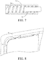
- the booster mechanism also comprises a spring, and the spring is in a compressed state under an action of a pulling force of the foldable screen fixed on the steel sheet (25) when the foldable screen of the foldable mobile terminal is in an unfolded state, and the spring releases a thrust that pushes the foldable screen to slide to both sides when the foldable screen of the foldable mobile terminal is restored to a folded state. As shown in FIGs.
- the spring is a compression spring 33
- the compression spring 33 is arranged in a cylindrical housing 31 with one end closed
- the cylindrical housing 31 is fixed on the bracket 26 of the foldable mobile terminal
- the compression spring 33 is connected to a head portion of the push rod 32 in the cylindrical housing 31
- an end of a rod part of the push rod 32 protrudes from the cylindrical housing 31 and abuts on the steel sheet 25, and a diameter of a head portion of the push rod 32 is greater than a diameter of an opening of the cylindrical housing 31, which is more reliable.
- the rod portion of the push rod 32 is compressed and the compression spring 33 gradually accumulates energy.
- the compression spring 33 releases the accumulated energy and pushes the folded screen to slide in the corresponding direction when the foldable screen of the foldable mobile terminal is restored to the folded state, thereby better preventing the problem of wrinkles and delamination in the existing foldable screen.
- the present application also provides a booster mechanism in other structural forms, and the booster mechanism also comprises a spring.
- One end of the spring is fixed on the steel sheet 25, and the other end of the spring abuts against the bracket 26 of the foldable mobile terminal (on a middle frame of the foldable mobile terminal).
- the spring is in a compressed state under the action of the pulling force of the foldable screen fixed on the steel sheet 25, that is, the spring is gradually in a state of storaging energy during the unfolding process of the screen.
- the cross section of the foldable screen at the bend can be a "water-drop" shape in cooperation with the rotation shaft mechanism. As shown in FIGs.
- a first fixing column 35 and a second fixing column 36 are fixed on the back of the steel sheet 25, and both the first fixing column 35 and the second fixing column 36 penetrate the bracket 26 of the foldable mobile terminal.
- the spring is a torsion spring 34, the main body of the torsion spring 34 is sleeved on the first fixing column 35, one end of the torsion spring 34 is fixed on the second fixing column 36, and the other end of the torsion spring 34 is pressed against the bracket 26 of the foldable mobile terminal. As shown in FIG.
- a stopper 38 extending from the outer side of the bracket 26 of the foldable mobile terminal is provided beside a through hole 37, and the other end of the torsion spring 34 abuts against the side surface of the stopper 38.
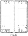
- the present embodiment has a total of four booster mechanisms arranged at the four positions of the bracket. In FIG. 13 , there are four booster mechanisms at positions B 1, B2, B3, and B4, that is, behind a foldable screen. Under the action of the symmetrically designed multiple booster mechanisms, the present application can smoothly reset the two ends of the foldable screen during the process of restoring the folded state of the foldable screen of the foldable mobile terminal, which significantly improves the usability of the foldable screen product. It better solves the problems of proneness to jamming and difficulty in restoring to the desired position on both sides of the existing foldable screen.
- the present application further provides a foldable mobile terminal comprising any foldable screen assembly disclosed above or any rotation shaft mechanism for foldable screens disclosed above.
- the foldable mobile terminals may be a portable electronic product with a foldable screen, such as a smart phone, a smart watch, a smart bracelet, a tablet computer, a notebook computer, or a smart wearable device (such as a smart helmet and smart glasses).
Landscapes
- Engineering & Computer Science (AREA)
- Signal Processing (AREA)
- Computer Hardware Design (AREA)
- Theoretical Computer Science (AREA)
- Human Computer Interaction (AREA)
- Physics & Mathematics (AREA)
- General Engineering & Computer Science (AREA)
- General Physics & Mathematics (AREA)
- Telephone Set Structure (AREA)
Applications Claiming Priority (2)
| Application Number | Priority Date | Filing Date | Title |
|---|---|---|---|
| CN201911208824.7A CN110958337B (zh) | 2019-11-30 | 2019-11-30 | 用于折叠屏的转轴机构、折叠屏组件及可折叠移动终端 |
| PCT/CN2019/124950 WO2021103161A1 (fr) | 2019-11-30 | 2019-12-12 | Mécanisme d'arbre rotatif pour écran pliable, ensemble écran pliable et terminal mobile pliable |
Publications (3)
| Publication Number | Publication Date |
|---|---|
| EP4068737A1 true EP4068737A1 (fr) | 2022-10-05 |
| EP4068737A4 EP4068737A4 (fr) | 2024-03-20 |
| EP4068737B1 EP4068737B1 (fr) | 2025-09-03 |
Family
ID=69979360
Family Applications (1)
| Application Number | Title | Priority Date | Filing Date |
|---|---|---|---|
| EP19950231.1A Active EP4068737B1 (fr) | 2019-11-30 | 2019-12-12 | Mécanisme d'arbre rotatif pour écran pliable, ensemble écran pliable et terminal mobile pliable |
Country Status (4)
| Country | Link |
|---|---|
| US (1) | US12041194B2 (fr) |
| EP (1) | EP4068737B1 (fr) |
| CN (1) | CN110958337B (fr) |
| WO (1) | WO2021103161A1 (fr) |
Families Citing this family (20)
| Publication number | Priority date | Publication date | Assignee | Title |
|---|---|---|---|---|
| US11615720B2 (en) * | 2020-08-26 | 2023-03-28 | Samsung Display Co., Ltd. | Display device |
| KR102346022B1 (ko) * | 2020-09-29 | 2022-01-03 | 주식회사 슈피겐코리아 | 사이드 커버가 회전하는 폴드 케이스 |
| CN112455260B (zh) * | 2020-11-12 | 2022-07-12 | 武汉合康智能电气有限公司 | 一种充电转换台及充电系统 |
| CN112769984B (zh) * | 2021-01-22 | 2023-05-23 | 维沃移动通信有限公司 | 折叠机构和电子设备 |
| CN113301198B (zh) * | 2021-06-21 | 2024-07-12 | 广东翼丰盛科技有限公司 | 一种便于安装的手机折叠屏用转轴结构 |
| CN115623711B (zh) * | 2021-07-16 | 2024-12-10 | 比亚迪股份有限公司 | 转轴组件及折叠屏终端 |
| CN113624463B (zh) * | 2021-08-13 | 2023-11-24 | 成都京东方光电科技有限公司 | 测试折叠屏最优转动轨迹的治具及方法 |
| CN113674629B (zh) * | 2021-09-07 | 2023-05-02 | 武汉华星光电半导体显示技术有限公司 | 显示装置 |
| CN115022426B (zh) | 2021-09-26 | 2023-04-07 | 荣耀终端有限公司 | 一种转动机构、支撑装置和折叠屏终端 |
| CN116800870B (zh) * | 2021-09-30 | 2024-10-01 | 荣耀终端有限公司 | 可折叠式移动终端 |
| CN115037817B (zh) * | 2021-11-08 | 2023-05-05 | 荣耀终端有限公司 | 凸轮组件、折叠机构、终端设备及凸轮组件的制作方法 |
| CN116168602B (zh) * | 2021-11-24 | 2026-01-16 | 北京小米移动软件有限公司 | 连接装置和终端设备 |
| CN114244934B (zh) * | 2021-12-29 | 2024-08-06 | 维沃移动通信有限公司 | 电子设备 |
| CN114706286B (zh) * | 2022-04-08 | 2023-06-16 | 深圳市芯科盈科技有限公司 | 一种方便进行分屏使用的智能手表 |
| CN119900757A (zh) * | 2022-08-22 | 2025-04-29 | 荣耀终端股份有限公司 | 转轴装置以及折叠屏设备 |
| CN118160024A (zh) * | 2022-08-31 | 2024-06-07 | 京东方科技集团股份有限公司 | 折叠机构及显示装置 |
| CN116095210A (zh) * | 2023-02-08 | 2023-05-09 | 安徽华创智能有限公司 | 一种用于手机屏内折的水滴型结构 |
| CN116336723B (zh) * | 2023-03-27 | 2024-10-18 | 海信冰箱有限公司 | 冰箱 |
| US20250234078A1 (en) * | 2024-01-17 | 2025-07-17 | Charles Atoe | Eagle |
| CN119737377A (zh) * | 2024-12-27 | 2025-04-01 | 深圳市泰衡诺科技有限公司 | 铰链机构与智能终端 |
Family Cites Families (10)
| Publication number | Priority date | Publication date | Assignee | Title |
|---|---|---|---|---|
| KR20130120703A (ko) * | 2012-04-26 | 2013-11-05 | 라이트-온 모바일 오와이제이 | 폴더형 풀플랫 휴대단말기 및 메카니즘 장치 |
| KR102202228B1 (ko) * | 2014-06-11 | 2021-01-13 | 삼성전자 주식회사 | 플렉서블 디스플레이를 포함하는 전자 장치 |
| KR102233119B1 (ko) * | 2014-09-23 | 2021-03-30 | 삼성디스플레이 주식회사 | 표시장치 |
| US10063677B2 (en) * | 2016-03-18 | 2018-08-28 | Motorola Mobility Llc | Electronic device with flexible display and hinged housing, and corresponding systems and methods |
| CN105979032B (zh) * | 2016-04-28 | 2018-03-27 | 广东欧珀移动通信有限公司 | 折叠机构及移动终端 |
| CN207777905U (zh) * | 2017-12-06 | 2018-08-28 | 杭州安费诺飞凤通信部品有限公司 | 一种内折柔性屏移动终端的铰链及内折柔性屏移动终端 |
| CN207977991U (zh) * | 2018-02-01 | 2018-10-16 | 杭州安费诺飞凤通信部品有限公司 | 一种内折柔性屏移动终端的铰链及内折柔性屏移动终端 |
| CN108322567B (zh) * | 2018-02-01 | 2019-11-08 | 杭州安费诺飞凤通信部品有限公司 | 一种内折柔性屏移动终端的铰链及内折柔性屏移动终端 |
| KR102085235B1 (ko) * | 2018-05-28 | 2020-03-05 | (주) 프렉코 | 폴더블 디스플레이 장치 |
| KR102375556B1 (ko) * | 2019-04-30 | 2022-03-17 | 삼성전자주식회사 | 힌지 구조물 및 이를 포함하는 전자 장치 |
-
2019
- 2019-11-30 CN CN201911208824.7A patent/CN110958337B/zh active Active
- 2019-12-12 EP EP19950231.1A patent/EP4068737B1/fr active Active
- 2019-12-12 WO PCT/CN2019/124950 patent/WO2021103161A1/fr not_active Ceased
- 2019-12-12 US US17/616,695 patent/US12041194B2/en active Active
Also Published As
| Publication number | Publication date |
|---|---|
| US12041194B2 (en) | 2024-07-16 |
| WO2021103161A1 (fr) | 2021-06-03 |
| CN110958337A (zh) | 2020-04-03 |
| US20220311847A1 (en) | 2022-09-29 |
| CN110958337B (zh) | 2021-08-03 |
| EP4068737B1 (fr) | 2025-09-03 |
| EP4068737A4 (fr) | 2024-03-20 |
Similar Documents
| Publication | Publication Date | Title |
|---|---|---|
| US12041194B2 (en) | Rotation shaft mechanism for foldable screen, foldable screen assembly, and foldable mobile terminal | |
| US11223710B2 (en) | Hinge of a mobile terminal having an inward-foldable flexible screen and a mobile terminal having an inward-foldable flexible screen | |
| US11194366B2 (en) | Semi-automatic hinge of a mobile terminal having an inward-foldable flexible screen and a mobile terminal having an inward-foldable flexible screen | |
| EP3739561B1 (fr) | Dispositif de support de corps d'écran et dispositif d'affichage flexible pliable | |
| EP3637742A1 (fr) | Articulation de terminal mobile à écran flexible et terminal mobile à écran flexible | |
| WO2019134693A1 (fr) | Charnière de terminal mobile comportant un écran souple pliable et terminal mobile comportant un écran souple pliable | |
| KR20220002630A (ko) | 힌지 기구 및 폴더블 이동 단말기 | |
| CN114198386B (zh) | 用于内折柔性屏移动终端的铰链 | |
| CN113534893B (zh) | 折叠式电子装置 | |
| CN115234572A (zh) | 铰链装置及柔性显示面板 | |
| WO2024027423A1 (fr) | Mécanisme d'arbre de rotation et appareil électronique | |
| CN110971725B (zh) | 用于折叠屏的滑轨机构、折叠屏组件及可折叠移动终端 | |
| CN116685087A (zh) | 移动终端及其折叠壳体 | |
| CN209881841U (zh) | 一种可折叠屏产品的滑板同步驱动机构 | |
| CN117662600B (zh) | 转轴装置以及折叠屏设备 | |
| CN101754619B (zh) | 手持电子装置 | |
| KR20130120703A (ko) | 폴더형 풀플랫 휴대단말기 및 메카니즘 장치 | |
| US20260016862A1 (en) | Hinge and foldable display device | |
| KR101144136B1 (ko) | 와이드 디스플레이부를 갖는 폴더형 휴대단말기 | |
| CN117128231B (zh) | 摆臂、转动机构及电子设备 | |
| CN102165703A (zh) | 滑动铰链装置 | |
| CN115623711A (zh) | 转轴组件及折叠屏终端 | |
| CN222376969U (zh) | 终端设备 | |
| CN220101798U (zh) | 折叠装置、折叠壳体及电子设备 | |
| KR101000000B1 (ko) | 힌지장치 및 이를 이용한 휴대 단말기 |
Legal Events
| Date | Code | Title | Description |
|---|---|---|---|
| STAA | Information on the status of an ep patent application or granted ep patent |
Free format text: STATUS: UNKNOWN |
|
| STAA | Information on the status of an ep patent application or granted ep patent |
Free format text: STATUS: THE INTERNATIONAL PUBLICATION HAS BEEN MADE |
|
| PUAI | Public reference made under article 153(3) epc to a published international application that has entered the european phase |
Free format text: ORIGINAL CODE: 0009012 |
|
| STAA | Information on the status of an ep patent application or granted ep patent |
Free format text: STATUS: REQUEST FOR EXAMINATION WAS MADE |
|
| 17P | Request for examination filed |
Effective date: 20210505 |
|
| AK | Designated contracting states |
Kind code of ref document: A1 Designated state(s): AL AT BE BG CH CY CZ DE DK EE ES FI FR GB GR HR HU IE IS IT LI LT LU LV MC MK MT NL NO PL PT RO RS SE SI SK SM TR |
|
| DAV | Request for validation of the european patent (deleted) | ||
| DAX | Request for extension of the european patent (deleted) | ||
| RIC1 | Information provided on ipc code assigned before grant |
Ipc: G06F 1/16 20060101ALI20231122BHEP Ipc: H04M 1/02 20060101AFI20231122BHEP |
|
| A4 | Supplementary search report drawn up and despatched |
Effective date: 20240219 |
|
| RIC1 | Information provided on ipc code assigned before grant |
Ipc: G06F 1/16 20060101ALI20240213BHEP Ipc: H04M 1/02 20060101AFI20240213BHEP |
|
| GRAP | Despatch of communication of intention to grant a patent |
Free format text: ORIGINAL CODE: EPIDOSNIGR1 |
|
| STAA | Information on the status of an ep patent application or granted ep patent |
Free format text: STATUS: GRANT OF PATENT IS INTENDED |
|
| INTG | Intention to grant announced |
Effective date: 20250402 |
|
| GRAS | Grant fee paid |
Free format text: ORIGINAL CODE: EPIDOSNIGR3 |
|
| P01 | Opt-out of the competence of the unified patent court (upc) registered |
Free format text: CASE NUMBER: APP_29448/2025 Effective date: 20250620 |
|
| GRAA | (expected) grant |
Free format text: ORIGINAL CODE: 0009210 |
|
| STAA | Information on the status of an ep patent application or granted ep patent |
Free format text: STATUS: THE PATENT HAS BEEN GRANTED |
|
| AK | Designated contracting states |
Kind code of ref document: B1 Designated state(s): AL AT BE BG CH CY CZ DE DK EE ES FI FR GB GR HR HU IE IS IT LI LT LU LV MC MK MT NL NO PL PT RO RS SE SI SK SM TR |
|
| REG | Reference to a national code |
Ref country code: CH Ref legal event code: EP |
|
| REG | Reference to a national code |
Ref country code: DE Ref legal event code: R096 Ref document number: 602019075382 Country of ref document: DE |
|
| REG | Reference to a national code |
Ref country code: IE Ref legal event code: FG4D |
|
| REG | Reference to a national code |
Ref country code: NL Ref legal event code: MP Effective date: 20250903 |
|
| PGFP | Annual fee paid to national office [announced via postgrant information from national office to epo] |
Ref country code: DE Payment date: 20251211 Year of fee payment: 7 |
|
| PGFP | Annual fee paid to national office [announced via postgrant information from national office to epo] |
Ref country code: GB Payment date: 20251219 Year of fee payment: 7 |
|
| PG25 | Lapsed in a contracting state [announced via postgrant information from national office to epo] |
Ref country code: NO Free format text: LAPSE BECAUSE OF FAILURE TO SUBMIT A TRANSLATION OF THE DESCRIPTION OR TO PAY THE FEE WITHIN THE PRESCRIBED TIME-LIMIT Effective date: 20251203 |
|
| REG | Reference to a national code |
Ref country code: LT Ref legal event code: MG9D |
|
| PG25 | Lapsed in a contracting state [announced via postgrant information from national office to epo] |
Ref country code: FI Free format text: LAPSE BECAUSE OF FAILURE TO SUBMIT A TRANSLATION OF THE DESCRIPTION OR TO PAY THE FEE WITHIN THE PRESCRIBED TIME-LIMIT Effective date: 20250903 |
|
| PG25 | Lapsed in a contracting state [announced via postgrant information from national office to epo] |
Ref country code: HR Free format text: LAPSE BECAUSE OF FAILURE TO SUBMIT A TRANSLATION OF THE DESCRIPTION OR TO PAY THE FEE WITHIN THE PRESCRIBED TIME-LIMIT Effective date: 20250903 |
|
| PGFP | Annual fee paid to national office [announced via postgrant information from national office to epo] |
Ref country code: FR Payment date: 20251229 Year of fee payment: 7 |
|
| PG25 | Lapsed in a contracting state [announced via postgrant information from national office to epo] |
Ref country code: GR Free format text: LAPSE BECAUSE OF FAILURE TO SUBMIT A TRANSLATION OF THE DESCRIPTION OR TO PAY THE FEE WITHIN THE PRESCRIBED TIME-LIMIT Effective date: 20251204 |
|
| PG25 | Lapsed in a contracting state [announced via postgrant information from national office to epo] |
Ref country code: SE Free format text: LAPSE BECAUSE OF FAILURE TO SUBMIT A TRANSLATION OF THE DESCRIPTION OR TO PAY THE FEE WITHIN THE PRESCRIBED TIME-LIMIT Effective date: 20250903 |
|
| PG25 | Lapsed in a contracting state [announced via postgrant information from national office to epo] |
Ref country code: LV Free format text: LAPSE BECAUSE OF FAILURE TO SUBMIT A TRANSLATION OF THE DESCRIPTION OR TO PAY THE FEE WITHIN THE PRESCRIBED TIME-LIMIT Effective date: 20250903 |
|
| PG25 | Lapsed in a contracting state [announced via postgrant information from national office to epo] |
Ref country code: PL Free format text: LAPSE BECAUSE OF FAILURE TO SUBMIT A TRANSLATION OF THE DESCRIPTION OR TO PAY THE FEE WITHIN THE PRESCRIBED TIME-LIMIT Effective date: 20250903 Ref country code: BG Free format text: LAPSE BECAUSE OF FAILURE TO SUBMIT A TRANSLATION OF THE DESCRIPTION OR TO PAY THE FEE WITHIN THE PRESCRIBED TIME-LIMIT Effective date: 20250903 |
|
| PG25 | Lapsed in a contracting state [announced via postgrant information from national office to epo] |
Ref country code: RS Free format text: LAPSE BECAUSE OF FAILURE TO SUBMIT A TRANSLATION OF THE DESCRIPTION OR TO PAY THE FEE WITHIN THE PRESCRIBED TIME-LIMIT Effective date: 20251203 |
|
| PG25 | Lapsed in a contracting state [announced via postgrant information from national office to epo] |
Ref country code: ES Free format text: LAPSE BECAUSE OF FAILURE TO SUBMIT A TRANSLATION OF THE DESCRIPTION OR TO PAY THE FEE WITHIN THE PRESCRIBED TIME-LIMIT Effective date: 20250903 |
|
| REG | Reference to a national code |
Ref country code: AT Ref legal event code: MK05 Ref document number: 1834584 Country of ref document: AT Kind code of ref document: T Effective date: 20250903 |
|
| PG25 | Lapsed in a contracting state [announced via postgrant information from national office to epo] |
Ref country code: NL Free format text: LAPSE BECAUSE OF FAILURE TO SUBMIT A TRANSLATION OF THE DESCRIPTION OR TO PAY THE FEE WITHIN THE PRESCRIBED TIME-LIMIT Effective date: 20250903 |
|
| PG25 | Lapsed in a contracting state [announced via postgrant information from national office to epo] |
Ref country code: SM Free format text: LAPSE BECAUSE OF FAILURE TO SUBMIT A TRANSLATION OF THE DESCRIPTION OR TO PAY THE FEE WITHIN THE PRESCRIBED TIME-LIMIT Effective date: 20250903 |
|
| PG25 | Lapsed in a contracting state [announced via postgrant information from national office to epo] |
Ref country code: AT Free format text: LAPSE BECAUSE OF FAILURE TO SUBMIT A TRANSLATION OF THE DESCRIPTION OR TO PAY THE FEE WITHIN THE PRESCRIBED TIME-LIMIT Effective date: 20250903 |
|
| PG25 | Lapsed in a contracting state [announced via postgrant information from national office to epo] |
Ref country code: RO Free format text: LAPSE BECAUSE OF FAILURE TO SUBMIT A TRANSLATION OF THE DESCRIPTION OR TO PAY THE FEE WITHIN THE PRESCRIBED TIME-LIMIT Effective date: 20250903 Ref country code: IT Free format text: LAPSE BECAUSE OF FAILURE TO SUBMIT A TRANSLATION OF THE DESCRIPTION OR TO PAY THE FEE WITHIN THE PRESCRIBED TIME-LIMIT Effective date: 20250903 |
|
| PG25 | Lapsed in a contracting state [announced via postgrant information from national office to epo] |
Ref country code: IS Free format text: LAPSE BECAUSE OF FAILURE TO SUBMIT A TRANSLATION OF THE DESCRIPTION OR TO PAY THE FEE WITHIN THE PRESCRIBED TIME-LIMIT Effective date: 20260103 |
|
| PG25 | Lapsed in a contracting state [announced via postgrant information from national office to epo] |
Ref country code: CZ Free format text: LAPSE BECAUSE OF FAILURE TO SUBMIT A TRANSLATION OF THE DESCRIPTION OR TO PAY THE FEE WITHIN THE PRESCRIBED TIME-LIMIT Effective date: 20250903 Ref country code: PT Free format text: LAPSE BECAUSE OF FAILURE TO SUBMIT A TRANSLATION OF THE DESCRIPTION OR TO PAY THE FEE WITHIN THE PRESCRIBED TIME-LIMIT Effective date: 20260105 |
|
| PG25 | Lapsed in a contracting state [announced via postgrant information from national office to epo] |
Ref country code: SK Free format text: LAPSE BECAUSE OF FAILURE TO SUBMIT A TRANSLATION OF THE DESCRIPTION OR TO PAY THE FEE WITHIN THE PRESCRIBED TIME-LIMIT Effective date: 20250903 Ref country code: EE Free format text: LAPSE BECAUSE OF FAILURE TO SUBMIT A TRANSLATION OF THE DESCRIPTION OR TO PAY THE FEE WITHIN THE PRESCRIBED TIME-LIMIT Effective date: 20250903 |