EP4068739A1 - Procédé d'affichage d'interface et dispositif électronique - Google Patents
Procédé d'affichage d'interface et dispositif électronique Download PDFInfo
- Publication number
- EP4068739A1 EP4068739A1 EP20892424.1A EP20892424A EP4068739A1 EP 4068739 A1 EP4068739 A1 EP 4068739A1 EP 20892424 A EP20892424 A EP 20892424A EP 4068739 A1 EP4068739 A1 EP 4068739A1
- Authority
- EP
- European Patent Office
- Prior art keywords
- interface
- icon
- electronic device
- region
- input
- Prior art date
- Legal status (The legal status is an assumption and is not a legal conclusion. Google has not performed a legal analysis and makes no representation as to the accuracy of the status listed.)
- Granted
Links
Images


Classifications
-
- H—ELECTRICITY
- H04—ELECTRIC COMMUNICATION TECHNIQUE
- H04M—TELEPHONIC COMMUNICATION
- H04M1/00—Substation equipment, e.g. for use by subscribers
- H04M1/72—Mobile telephones; Cordless telephones, i.e. devices for establishing wireless links to base stations without route selection
- H04M1/724—User interfaces specially adapted for cordless or mobile telephones
- H04M1/72448—User interfaces specially adapted for cordless or mobile telephones with means for adapting the functionality of the device according to specific conditions
- H04M1/72454—User interfaces specially adapted for cordless or mobile telephones with means for adapting the functionality of the device according to specific conditions according to context-related or environment-related conditions
-
- H—ELECTRICITY
- H04—ELECTRIC COMMUNICATION TECHNIQUE
- H04M—TELEPHONIC COMMUNICATION
- H04M1/00—Substation equipment, e.g. for use by subscribers
- H04M1/72—Mobile telephones; Cordless telephones, i.e. devices for establishing wireless links to base stations without route selection
- H04M1/724—User interfaces specially adapted for cordless or mobile telephones
- H04M1/72469—User interfaces specially adapted for cordless or mobile telephones for operating the device by selecting functions from two or more displayed items, e.g. menus or icons
Definitions
- Embodiments of the present invention relate to the field of communication technologies, and in particular, to an interface display method and an electronic device.
- the notification bar is usually hidden in a screen of an electronic device, to check a notification message in the notification bar, a user may swipe down from a top edge of the screen to pull out the notification bar.
- the notification message in the notification bar is usually displayed in the form of a list in the middle region of the notification bar. Consequently, the blank area of the notification bar is wasted, resulting in a low layout space utilization of the notification bar.
- Embodiments of the present invention provide an interface display method and an electronic device, to resolve the problem of a low layout space utilization of an existing notification bar of an electronic device in a landscape state.
- the embodiments of the present invention provide an interface display method, including:
- the embodiments of the present invention further provide an electronic device, including:
- the embodiments of the present invention provide an electronic device, including a processor, a memory, and a computer program stored in the memory and executable on the processor, wherein when the computer program is executed by the processor, steps of the interface display method as described in the first aspect are implemented.
- the embodiments of the present invention further provide a computer-readable storage medium, storing a computer program, wherein when the computer program is executed by a processor, steps of the interface display method as described in the first aspect are implemented.
- the electronic device in a case that the electronic device is in a landscape state and displays a first interface of a first application, after receiving a first input performed by a user, displays a notification bar interface including a first region and a second region. Because the first region displays N first icons indicating a first object or first objects, and the second region is configured to display a notification message, the notification bar interface can further display icons in addition to retaining the original function of displaying a notification message, so that the notification bar interface is effectively utilized, thereby avoiding the problem of a low layout space utilization of an existing notification bar of an electronic device in a landscape state.
- A/B may represent A or B.
- And/or herein describes only an association relationship between associated objects and represents that three relationships may exist.
- a and/or B may represent the following three cases: Only A exists, both A and B exist, and only B exists.
- the word, such as “exemplarily” or “for example”, is used to represent giving an example, an illustration, or a description. Any embodiment or design scheme described with “exemplarily” or “for example” in the embodiments of the present invention should not be explained as being more preferred or having more advantages than another embodiment or design scheme. Exactly, use of the word, such as “exemplarily” or “for example”, is intended to present a related concept in a specific manner.
- words, such as “first” and “second”, are used to distinguish same or similar items with basically same functions or effects.
- words, such as “first” and “second” do not define the amount and the operating sequence.
- the first input and the second input first are intended to distinguish between different inputs rather than describe a particular order of inputs.
- a user may pull down the notification bar.
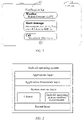
- a screen (that is, 11 in FIG. 1 ) of an electronic device displays a notification bar interface (that is, 12 in FIG. 1 ), and displays three notification messages, namely, a "Weather” notification message, a "Short message” notification message, and a "Call” notification message, in the form of a list in the middle region of the notification bar interface 12.
- the notification bar interface 12 displays the notification messages only in the middle region, and other blank area is wasted, resulting in a low layout space utilization of the notification bar.
- the embodiments of the present invention provide an interface display method. After receiving a first input performed by a user, the electronic device displays a notification bar interface including a first region and a second region. Because the first region is configured to display a notification message, and the second region is configured to display a first icon indicating a first object, the notification bar interface can further display an icon in addition to retaining the original function of displaying a notification message, so that the notification bar interface is effectively utilized, thereby avoiding the problem of a low layout space utilization of an existing notification bar of an electronic device in a landscape state.
- the interface display method provided in the embodiments of the present invention may be performed by the electronic device (including a mobile electronic device and a non-mobile electronic device), or may be performed by a function module and/or a function entity that is in the electronic device and that can implement the interface display method, which may be specifically determined according to actual use requirements, and is not limited in the embodiments of the present invention.
- the interface display method provided in the embodiments of the present invention is illustrated below.
- the electronic device in the embodiments of the present invention may be a mobile electronic device or a non-mobile electronic device.
- the mobile electronic device may be a mobile phone, a tablet computer, a notebook computer, a palmtop computer, an in-vehicle electronic device, a wearable device, an ultra-mobile personal computer (ultra-mobile personal computer, UMPC), a netbook, a personal digital assistant (personal digital assistant, PDA), or the like.
- the non-mobile electronic device may be a personal computer (personal computer, PC), a television (television, TV), an automatic teller machine, a self-service machine, or the like, which is not specifically limited in the embodiments of the present invention.
- the electronic device in the embodiments of the present invention may be an electronic device having an operating system.
- the operating system may be an Android (Android) operating system, an iOS operating system, or another possible operating system, which is not specifically limited in the embodiments of the present invention.
- FIG. 2 is a possible schematic architectural diagram of an Android operating system according to an embodiment of the present invention.
- an architecture of the Android operating system includes four layers, namely, an application layer, an application framework layer, a system runtime layer, and a kernel layer (specifically, a Linux kernel layer).
- the application layer includes applications in the Android operating system (including system applications and third-party applications).
- the application framework layer is a framework of an application. Developers may develop some applications based on the application framework layer under the condition of complying with the development principles of the framework of the application.
- the system runtime layer includes libraries (also referred to as system libraries) and an Android operating system runtime environment.
- the libraries mainly provide various resources required by the Android operating system.
- the Android operating system runtime environment is configured to provide a software environment for the Android operating system.
- the kernel layer is an operating system layer of the Android operating system, and belongs to the underlying layer of software layers of the Android operating system.
- the kernel layer provides core system services and hardware-related drivers for the Android operating system based on the Linux kernel.
- the developers may develop, based on the system architecture of the Android operating system shown in FIG. 2 above, a software program implementing the interface display method provided in the embodiments of the present invention, so that the interface display method is executable based on the Android operating system shown in FIG. 2 . That is, the processor or electronic device can implement the interface display method provided in the embodiments of the present invention by running the software program in the Android operating system.
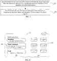
- FIG. 3 is a schematic flowchart of an interface display method according to an embodiment of the present invention, including step 201 and step 202:
- Step 201 An electronic device receives a first input performed by a user in a case that the electronic device is in a landscape state and displays a first interface of a first application.
- the first input performed by the user may specifically include: a tap input performed by the user on a screen, or a swipe input performed by the user on the screen, or another feasible input performed by the user on the screen, which may be specifically determined according to actual use requirements, and is not limited in the embodiments of the present invention.
- the tap input herein may be a single-tap input, a double-tap input, an input of any quantity of taps, or the like.
- the tap input may alternatively be a long-press input or a short-press input.
- the swipe input herein may be a swipe input in any direction, for example, swipe-up, swipe-down, slide-left or swipe-right, and a swiping trajectory of the above swipe input may be a straight line or a curve, which may be specifically set according to actual requirements.
- the swipe input performed by the user on the screen may specifically include: a swipe-down input performed by the user on the screen.
- a swipe-down input performed by the user on the screen For example, the user swipes down from a top edge of the screen of the electronic device to pull out a notification bar (a drop-down notification bar for short).
- Step 202 The electronic device displays, in response to the first input, a notification bar interface and N first icons in a first region.
- the notification bar interface includes a first region and a second region.
- the first region displays N first icons, and the second region is configured to display a notification message.
- a first icon is configured to indicate a first object, and N is a positive integer.
- step 202 in execution, there is no obvious sequential order between that the electronic device displays the notification bar interface and that the electronic device displays N first icons in the first region.
- the electronic device may display N first icons on the first region before the electronic device displays the notification bar interface, or after the electronic device displays the notification bar interface, or while the electronic device displays the notification bar interface, which is not limited in the embodiments of the present invention.
- the first region can display controls in addition to the first icons.
- the electronic device may display a video barrage sending control in the first region, that is, use the first region as a video barrage sending entry.
- the first region may be at any position in the notification bar interface
- the second region may be at any position that is in the notification bar interface and that is different from that of the first region, which is not limited in the embodiments of the present invention.
- the first region may be set in the left region of the notification bar interface, and the second region may be set in the right region of the notification bar interface.
- the first region may be set in the right region of the notification bar interface, and the second region may be set in the left region of the notification bar interface.
- the first region may be set in the upper region of the notification bar interface, and the second region may be set in the lower region of the notification bar interface.
- the first region may be set in the lower region of the notification bar interface, and the second region may be set in the upper region of the notification bar interface.
- the electronic device may set the left region of the notification bar interface as the second region and the right region of the notification bar interface as the first region.
- the electronic device may display notification messages in the form of a list in the second region, and may display an application Launcher (desktop application) task in the first region.
- the electronic device may display the first icons in the first region in a paginated manner.
- the first object may include at least one of the following: an application, a multimedia file, or an image.
- the multimedia file may be audio or a video.
- the first icon may be an icon configured to trigger a multimedia file corresponding to the first icon, or may be a thumbnail configured to trigger an image corresponding to the first icon.
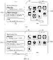
- the screen of the electronic device displays a notification bar interface (that is, 32 in FIG. 4 ), and the notification bar interface 32 includes a second region (that is, 32a in FIG. 4 ) and a first region (that is, 32b in FIG. 4 ).
- the second region 32a displays three notification messages in the form of a list
- the first region 32b displays six video icons, namely, "Recommended video 1" to "Recommended video 6" video icons.
- the electronic device displays an interface corresponding to the "Weather” notification message. If the user taps the "Recommended video 1" video icon, the electronic device displays a video interface corresponding to the "Recommended video 1".
- the first icon when the first object is an application, the first icon may be an application icon of an application corresponding to the first icon, or may be an icon configured to trigger a shortcut of the application corresponding to the first icon, or may be another icon that can uniquely identify the application corresponding to the first icon, which may be specifically determined according to actual use requirements and is not limited in the embodiments of the present invention.
- the screen of the electronic device displays a notification bar interface (that is, 42 in FIG. 5 )
- the notification bar interface 42 includes a second region (that is, 42a in FIG. 5 ) and a first region (that is, 42b in FIG. 5 ).
- the second region 42a displays three notification messages in the form of a list
- the first region 42b displays eight video icons, namely, "Application 1" to "Application 8" application icons.
- the electronic device displays an interface corresponding to the "Weather” notification message. If the user taps the "Application 1" application icon, the electronic device displays a main interface of the "Application 1".
- the application may include: a portrait application and/or a landscape application.
- the landscape application means that interfaces of some applications are only adapted to the electronic device in a landscape state.
- the portrait application means that interfaces of some applications are only adapted to the electronic device in a portrait state.
- the electronic device can switch from one landscape application to another landscape application in a case that the electronic device remains in the landscape state.
- the electronic device currently displays a main interface of a landscape application, and when a user wants to open another landscape application "Application 1", the user may pull down the notification bar.
- the electronic device displays, in the first region 42b, entry Launchers of all applications that have been installed on the electronic device and that are adapted to the landscape state, that is, displays eight landscape application icons, namely, "Application 1" to "Application 8" application icon.
- the user may tap the "Application 1" application icon, and the electronic device directly switches to a main interface of the "Application 1".
- the electronic device in a case that the electronic device is in a landscape state and displays a first interface of a first application, the electronic device displays a notification bar interface including a first region and a second region. Because the first region displays N first icons indicating a first object or first objects, and the second region is configured to display a notification message, the notification bar interface can further display icons in addition to retaining the original function of displaying a notification message, so that the notification bar interface is effectively utilized, thereby avoiding the problem of a low layout space utilization of an existing notification bar of an electronic device in a landscape state.
- the electronic device may use the first region as an entry for multi-scenario interaction of other applications, that is, and icons corresponding to objects related to or the same as the interface content may be displayed in the first region, so that a user can enter another application by touching the icon.
- Step 203a The electronic device receives a second input for a target first icon in the N first icons.
- the first object indicated by the target first icon is a second interface.
- the second interface is an interface adapted to the electronic device in the landscape state.
- the second input may specifically include: a tap input performed by the user on the target first icon, or a swipe input performed by the user on the target first icon, or another feasible input performed by the user on the target first icon, which may be specifically determined according to actual use requirements, and is not limited in the embodiments of the present invention.
- Step 203b The electronic device displays the second interface in the landscape state in response to the second input.
- the second interface may be an interface in the first application, or may be an interface in a second application, which is not limited in the embodiments of the present invention.
- a conventional video playback interface is adapted to an electronic device in a portrait state by default, and a playback interface (that is, the second interface) adapted to the electronic device in a landscape state is displayed only after a user taps a "Full screen playback" key.
- the electronic device may search for related recommended objects in other applications connected to the first region and display the recommended objects in the first region.
- related recommended objects are searched for according to an application type of a currently working application in applications of the same type, and recommend and display the related recommended objects in the first region, which are not limited in the present invention.
- Example 1 When the electronic device is in the landscape state and plays a video a, the electronic device obtains video content (for example, lines or pictures) of the video a. Next, the electronic device may notify other video applications of the video content, search for recommended videos related to the video content in the other video applications, and then recommend and display the recommended videos to the user, that is, display video icons of the recommended videos in the first region of the notification bar interface.
- the user may pull down the notification bar (that is, the first input). In this case, as shown in FIG. 4 , the electronic device displays "Recommended video 1" to "Recommended video 6" video icons in the first region 32b. If the user taps the "Recommended video 1" video icon (that is, the second input), the electronic device may switch to a playback interface of the "Recommended video 1", and perform automatic playback.
- Example 2 When the electronic device is in the landscape state and plays a video a.
- the user may pull down the notification bar (that is, the first input).
- the electronic device may be triggered to obtain video content (for example, lines or pictures) of the video a.
- the electronic device may notify other video applications of the video content, search for recommended videos related to the video content in the other video applications, and then recommend and display the recommended videos to the user, that is, display video icons of the recommended videos in the first region of the notification bar interface.
- the electronic device displays "Recommended video 1" to "Recommended video 6" video icons in the first region 32b. If the user taps the "Recommended video 1" video icon, the electronic device may switch to a playback interface of the "Recommended video 1", and perform automatic playback.
- the electronic device may close the notification bar interface.
- the electronic device can recommend related objects for the user according to interface content of a current interface, so that the user can quickly check the related objects and select a to-be-viewed object, and then open the object, so that all the operations are simple and fast.
- the electronic device may further remove an existing icon before displaying the icons in the first region.
- step 201b1 the method may further include step 201b1 as follows: Step 201b1: The electronic device removes, if the first region displays a second icon, the second icon in a case that the electronic device displays the first interface in the landscape state.
- the second icon is configured to indicate a second object, and the second object is unrelated to the interface content of the first interface.
- the second object may include at least one of the following: an application, a multimedia file, or an image.
- the multimedia file may be audio or a video.
- the second icon may be an icon configured to trigger a multimedia file corresponding to the second icon, or may be a thumbnail configured to trigger an image corresponding to the second icon.
- the second icon may be an application icon of an application corresponding to the second icon, or may be an icon configured to trigger a shortcut of the application corresponding to the second icon, or may be another icon that can uniquely identify the application corresponding to the second icon, which may be specifically determined according to actual use requirements and is not limited in the embodiments of the present invention.
- the first region of the notification bar interface displays song icons of related recommended songs.
- a playback interface of a video a is entered.
- the user may pull down the notification bar (that is, the first input).
- the electronic device is triggered to obtain lines on the playback interface of the video a, and extract key words therefrom.
- the electronic device may search for related recommended videos in other video applications by using the keywords.
- the electronic device may first remove the song icons of the related recommended songs displayed in the first region. As shown in FIG. 4 , the electronic device displays "Recommended video 1" to "Recommended video 6" video icons in the first region 32b.
- the user may add an icon into the first region according to a need after the electronic device displays the notification bar interface.
- the method may further include step 204 to step 207 as follows: Step 204: The electronic device receives a third input for the first region.
- the third input for the first region may specifically include: a tap input performed by the user on a screen, or a swipe input performed by the user on the screen, or another feasible input performed by the user on the screen, which may be specifically determined according to actual use requirements, and is not limited in the embodiments of the present invention.
- the third input may be an input performed by the user on the first region.
- the third input is an input performed by the user on the blank area of the first region.
- tap input and swipe input refer to the descriptions of the first input in this application. Details are not described herein again.
- Step 205 The electronic device displays an icon setting interface in response to the third input.
- the icon setting interface displays X third icons, a third icon is configured to indicate a third object, and X is a positive integer.
- the icon setting interface may be superimposed and displayed on the notification bar interface.
- the icon setting interface may be superimposed and displayed on the notification bar interface at a first transparency.
- a value range of T1 may be 0% ⁇ T1 ⁇ 100%.
- the icon setting interface may be displayed at any position in the notification bar interface.
- a size of the icon setting interface may be a default size or may be set by the user flexibly.
- the third object may include at least one of the following: an application, a multimedia file, or an image.
- the multimedia file may be audio or a video.
- the third icon may be an icon configured to trigger a multimedia file corresponding to the third icon, or may be a thumbnail configured to trigger an image corresponding to the third icon.
- the third icon may be an application icon of an application corresponding to the third icon, or may be an icon configured to trigger a shortcut of the application corresponding to the third icon, or may be another icon that can uniquely identify the application corresponding to the third icon, which may be specifically determined according to actual use requirements and is not limited in the embodiments of the present invention.
- Step 206 The electronic device receives a fourth input for a target third icon.
- the fourth input for the target third icon may specifically include: a tap input performed by the user on the target third icon, or a swipe input performed by the user on the target third icon, or another feasible input performed by the user on the target third icon, which may be specifically determined according to actual use requirements, and is not limited in the embodiments of the present invention.
- tap input and swipe input refer to the descriptions of the first input in this application. Details are not described herein again.
- Step 207 The electronic device adds the target third icon into the first region in response to the fourth input.
- the target third icon is at least one of the X third icons.
- the user when the user wants to add an application icon, the user may long-press the blank area of the first region 42b (that is, the third input), and when the user long-presses the blank area of the first region 42b, as indicated by (a) in FIG. 6 , the icon setting interface (that is, 51 in (a) in FIG. 6 ) is superimposed on the notification bar interface 42, and four application icons (that is, the third icons) are displayed in the icon setting interface 51.
- the four application icons are respectively an "Application 9" application icon, an "Application 10" application icon, an "Application 11" application icon, and an "Application 12" application icon.
- the user can tap the "Application 9" application icon (that is, the target third identifier), as indicated by (b) in FIG. 6 , and the electronic device may add the "Application 9" application icon into the first region 42b.
- the user may choose a to-be-added application icon in the icon setting interface according to preferences and requirements, so as to add an application icon of a to-be-used application into the first region, thereby improving the sense of human-computer interaction.
- Step A1 The electronic device displays the notification bar interface in response to the first input, and displays the first icons in the notification bar interface according to use frequencies of all applications in a plurality of applications.
- the first icons may be displayed in descending order according to the use frequencies of all the applications in the plurality of applications or may be displayed in ascending order according to the use frequencies of all the applications in the plurality of applications, which is not limited in the present invention.
- the electronic device may display the first icons according to use habits of the user, so that the user can quickly find an application that the user wants to use, thereby improving operation efficiency.
- the electronic device may further divide the notification bar interface into a first region and a second region in a case that the electronic device is in the portrait state, so that the layout of the notification bar interface of the electronic device in the portrait state can be further redesigned, which enriches interaction modes of the notification bar of the electronic device in the portrait state in different scenarios.
- the notification bar interface of the electronic device in the landscape state in this embodiment of the present invention. Details are not described herein again.
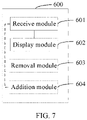
- FIG. 7 is a possible schematic structural diagram of implementing an electronic device according to an embodiment of the present invention.
- an electronic device 600 includes: a receive module 601 and a display module 602.
- the receive module 601 is configured to receive a first input performed by a user in a case that an electronic device is in a landscape state and displays a first interface of a first application.
- the display module 602 is configured to display a notification bar interface in response to the first input received by the receive module 601, and display N first icons in a first region, where the notification bar interface includes the first region and a second region, the second region is configured to display a notification message, a first icon is configured to indicate a first object, and N is a positive integer.
- the first object is related to interface content of the first interface.
- the receive module 601 is further configured to receive a second input for a target first icon in the N first icons, where a first object indicated by the target first icon is a second interface.
- the display module 602 is further configured to display the second interface in the landscape state in response to the second input received by the receive module 601.
- the electronic device 600 further includes: a removal module 603.
- the removal module 603 is configured to remove, if the first region displays a second icon, the second icon, where the second icon is configured to indicate a second object, and the second object is unrelated to the interface content of the first interface.
- the electronic device 600 further includes: an addition module 604.
- the receive module 601 is further configured to receive a third input for the first region.
- the display module 602 is further configured to display an icon setting interface in response to the third input received by the receive module 601, where the icon setting interface displays X third icons, and a third icon is configured to indicate a third object.
- the receive module 601 is further configured to receive a fourth input for a target third icon.
- the addition module 604 is configured to add the target third icon to the first region in response to the fourth input received by the receive module 601, where the target third icon is at least one of the X third icons, and X is a positive integer.
- a module that is necessarily included in the electronic device 600 is indicated by a solid line box, for example, the receive module 601, and a module that may not be included in the electronic device 600 is indicated by a dashed line box, for example, the addition module 604.
- the electronic device in a case that a terminal device is in a landscape state and displays a first interface of a first application, the electronic device displays a notification bar interface including a first region and a second region. Because the first region displays N first icons indicating a first object or first objects, and the second region is configured to display a notification message, the notification bar interface can further display icons in addition to retaining the original function of displaying a notification message, so that the notification bar interface is effectively utilized, thereby avoiding the problem of a low layout space utilization of an existing notification bar of an electronic device in a landscape state.
- the electronic device provided in this embodiment of the present invention can implement various processes implemented by the electronic device in the method embodiments. To avoid repetition, details are not described herein again.
- FIG. 8 is a schematic diagram of a hardware structure of an electronic device 100 according to embodiment of the present invention.
- the electronic device 100 includes, but is not limited to, components such as a radio frequency unit 101, a network module 102, an audio output unit 103, an input unit 104, a sensor 105, a display unit 106, a user input unit 107, an interface unit 108, a memory 109, a processor 110, and a power supply 111.
- a person skilled in the art may understand that the structure of the electronic device 100 shown in FIG. 8 does not constitute a limitation to the electronic device.
- the electronic device 100 may include more or fewer components than those shown in the figure, or some components may be combined, or a different component deployment may be used.
- the electronic device 100 includes, but is not limited to, a mobile phone, a tablet computer, a notebook computer, a palmtop computer, an in-vehicle electronic device, a wearable device, a pedometer, and the like.
- the processor 110 is configured to control the user input unit 107 to receive a first input performed by a user in a case that the electronic device is in a landscape state and displays a first interface of a first application; and is further configured to control the display unit 106 to display a notification bar interface in response to the first input received by the user input unit 107, and display N first icons in a first region, where the notification bar interface includes the first region and a second region, the second region is configured to display a notification message, a first icon is configured to indicate a first object, and N is a positive integer.
- the electronic device in a case that a terminal device is in a landscape state and displays a first interface of a first application, the electronic device displays a notification bar interface including a first region and a second region. Because the first region displays N first icons indicating a first object or first objects, and the second region is configured to display a notification message, the notification bar interface can further display icons in addition to retaining the original function of displaying a notification message, so that the notification bar interface is effectively utilized, thereby avoiding the problem of a low layout space utilization of an existing notification bar of an electronic device in a landscape state.
- the radio frequency unit 101 may be configured to receive and transmit information or receive and transmit signals during a call. Specifically, after being received, downlink data from a base station is processed by the processor 110. In addition, uplink data is sent to the base station.
- the radio frequency unit 101 includes, but is not limited to, an antenna, at least one amplifier, a transceiver, a coupler, a low noise amplifier, a duplexer, and the like. In addition, the radio frequency unit 101 may further communicate with another device through a wireless communication system and network.
- the electronic device 100 provides wireless broadband Internet access for a user through the network module 102, for example, help the user to send and receive emails, browse webpages, and access stream media, and the like.
- the audio output unit 103 may convert audio data received by the radio frequency unit 101 or network module 102 or audio data stored in the memory 109 into audio signals and output the audio signals as sounds. Moreover, the audio output unit 103 may further provide an audio output (for example, a call signal receiving sound or a message receiving sound) related to a specific function implemented by the electronic device 100.
- the audio output unit 103 includes a speaker, a buzzer, a receiver, and the like.
- the input unit 104 is configured to receive an audio signal or a video signal.
- the input unit 104 may include a graphics processing unit (Graphics Processing Unit, GPU) 1041 and a microphone 1042.
- the graphics processing unit 1041 processes image data of a static picture or a video obtained by an image capturing apparatus (for example, a camera) in a video capturing mode or an image capturing mode. An image frame that has been processed may be displayed on a display unit 106.
- the image frame that has been processed by the graphics processing unit 1041 may be stored in the memory 109 (or another storage medium) or sent by using the radio frequency unit 101 or network module 102.
- the microphone 1042 may receive a sound, and can process the sound into audio data.
- the processed audio data may be converted, in a phone call mode, into a format that may be sent to a mobile communication base station via the radio frequency unit 101 and be output.
- the electronic device 100 further includes at least one sensor 105 such as an optical sensor, a motion sensor, and other sensors.
- the optical sensor includes an ambient light sensor and a proximity sensor.
- the ambient light sensor may adjust luminance of the display panel 1061 according to brightness of the ambient light.
- the proximity sensor may switch off the display panel 1061 and/or backlight when the electronic device 100 is moved to the ear.
- an acceleration sensor can detect magnitudes of accelerations in various directions (generally, on three axes), may detect a magnitude and a direction of the gravity in a static state, and may be applied to recognizing an attitude of the electronic device (for example, switching between a landscape state and a portrait state, a related game, and magnetometer attitude calibration), a function related to vibration recognition (such as a pedometer and a knock), and the like.
- the sensor 105 may further include a fingerprint sensor, a pressure sensor, an iris sensor, a molecular sensor, a gyroscope, a barometer, a hygrometer, a thermometer, an infrared sensor, and the like, and details are not described herein.
- the display unit 106 is configured to display information entered by the user or information provided for the user.
- the display unit 106 may include a display panel 1061.
- the display panel 1061 may be configured in the form of a liquid crystal display (LCD), an organic light-emitting diode (OLED), or the like.
- the user input unit 107 may be configured to receive input digit or character information, and generate a keyboard signal input related to the user setting and function control of the electronic device 100.
- the user input unit 107 includes a touch panel 1071 and another input device 1072.
- the touch panel 1071 also referred to as a touchscreen, may collect a touch operation of a user on or near the touch panel (such as an operation of a user on or near the touch panel 1071 by using any suitable object or attachment such as a finger or a touch pen).
- the touch panel 1071 may include two parts: a touch detection apparatus and a touch controller.
- the touch detection apparatus detects a touch orientation of the user, detects a signal brought by the touch operation, and transmits the signal to the touch controller.
- the touch controller receives touch information from the touch detection apparatus, converts the touch information into a contact coordinate, then transmits the contact coordinate to the processor 110, and receives and executes a command transmitted by the processor 110.
- the touch panel 1071 may be implemented by using various types, such as a resistive type, a capacitive type, an infrared type, and a surface acoustic wave type.
- the user input unit 107 may further include the another input device 1072.
- the another input device 1072 may include, but not limited to, a physical keyboard, a functional key (such as a volume control key or a switch key), a track ball, a mouse, and a joystick, which is not described herein in detail.
- the touch panel 1071 may cover the display panel 1061. After detecting a touch operation on or near the touch panel 1071, the touch panel 1071 transfers the touch operation to the processor 110, to determine a type of a touch event. Then, the processor 110 provides a corresponding visual output on the display panel 1061 according to the type of the touch event.
- the touch panel 1071 and the display panel 1061 are used as two separate parts to implement input and output functions of the electronic device 100, in some embodiments, the touch panel 1071 and the display panel 1061 may be integrated to implement the input and output functions of the electronic device 100, which is not specifically limited herein.
- the interface unit 108 is an interface between an external apparatus and the electronic device 100.
- the external apparatus may include a wired or wireless headset port, an external power supply (or a battery charger) port, a wired or wireless data port, a storage card port, a port used to connect an apparatus having an identification module, an audio input/output (I/O) port, a video I/O port, an earphone port, and the like.
- the interface unit 108 may be configured to receive an input (for example, data information or power) from an external apparatus, and transmit the received input to one or more elements in the electronic device 100, or may be configured to transmit data between the electronic device 100 and the external apparatus.
- the memory 109 may be configured to store a software program and various data.
- the memory 109 may mainly include a program storage area and a data storage area.
- the program storage area may store an operating system, an application program required by at least one function (for example, a sound playback function and an image playback function), or the like.
- the data storage area may store data (for example, audio data and a phone book) created according to use of the mobile phone.
- the memory 109 may include a high speed random access memory, and may further include a non-volatile memory, such as at least one magnetic disk storage device, a flash memory device or other non-volatile solid state storage devices.
- the processor 110 is a control center of the electronic device 100, and connects to various parts of the electronic device 100 by using various interfaces and lines. By running or executing the software program and/or the module stored in the memory 109, and invoking data stored in the memory 109, the processor 110 performs various functions and data processing of the electronic device 100, thereby performing overall monitoring on the electronic device 100.
- the processor 110 may include one or more processing units.
- the processor 110 may integrate an application processor and a modem processor, where the application processor mainly processes an operating system, a user interface, an application program, and the like, and the modem processor mainly processes wireless communication. It may be understood that the foregoing modem may either not be integrated into the processor 110.
- the electronic device 100 further includes the power supply 111 (such as a battery) for supplying power to the components.
- the power supply 111 may be logically connected to the processor 110 by a power management system, thereby implementing functions, such as charging, discharging, and power consumption management, by using the power management system.
- the electronic device 100 includes some function modules that are not shown, which is not described herein in detail.
- the embodiments of the present invention further provide an electronic device, including a processor, a memory, and a computer program stored in the memory and executable on the processor 110, where when executed by the processor, the computer program implements respective processes of the embodiments of the interface display method, and can achieve the same technical effects. To avoid repetition, details are not described herein again.
- the embodiments of the present invention further provide a computer-readable storage medium, storing a computer program, where when executed by a processor, the computer program implements respective processes of the embodiments of the interface display method, and can achieve the same technical effects. To avoid repetition, details are not described herein again.
- the computer-readable storage medium is, for example, a read-only memory (Read-Only Memory, ROM for short), a random access memory (Random Access Memory, RAM for short), a magnetic disk, or an optical disc.
- the foregoing embodiment methods may be implemented by using software in combination with a necessary universal hardware platform.
- the embodiment methods may alternatively be implemented by using hardware, but the former is a better implementation in many cases.
- the technical solutions in this application essentially or the part contributing to the related art may be implemented in the form of a software product.
- the computer software product is stored in a storage medium (for example, a ROM/RAM, a magnetic disk, or an optical disc), and includes several instructions for instructing an electronic device (which may be a smartphone, a computer, a server, an air-conditioner, a network device, or the like) to perform the method described in the embodiments of this application.
Landscapes
- Engineering & Computer Science (AREA)
- Human Computer Interaction (AREA)
- Computer Networks & Wireless Communication (AREA)
- Signal Processing (AREA)
- Environmental & Geological Engineering (AREA)
- User Interface Of Digital Computer (AREA)
- Telephone Function (AREA)
Applications Claiming Priority (2)
| Application Number | Priority Date | Filing Date | Title |
|---|---|---|---|
| CN201911184572.9A CN111049976B (zh) | 2019-11-27 | 2019-11-27 | 界面显示方法、电子设备及计算机可读存储介质 |
| PCT/CN2020/130775 WO2021104193A1 (fr) | 2019-11-27 | 2020-11-23 | Procédé d'affichage d'interface et dispositif électronique |
Publications (3)
| Publication Number | Publication Date |
|---|---|
| EP4068739A1 true EP4068739A1 (fr) | 2022-10-05 |
| EP4068739A4 EP4068739A4 (fr) | 2023-01-11 |
| EP4068739B1 EP4068739B1 (fr) | 2025-10-08 |
Family
ID=70233783
Family Applications (1)
| Application Number | Title | Priority Date | Filing Date |
|---|---|---|---|
| EP20892424.1A Active EP4068739B1 (fr) | 2019-11-27 | 2020-11-23 | Procédé d'affichage d'interface et dispositif électronique |
Country Status (6)
| Country | Link |
|---|---|
| US (1) | US12388924B2 (fr) |
| EP (1) | EP4068739B1 (fr) |
| JP (1) | JP7467625B2 (fr) |
| CN (1) | CN111049976B (fr) |
| ES (1) | ES3051583T3 (fr) |
| WO (1) | WO2021104193A1 (fr) |
Families Citing this family (7)
| Publication number | Priority date | Publication date | Assignee | Title |
|---|---|---|---|---|
| CN111049976B (zh) | 2019-11-27 | 2021-05-28 | 维沃移动通信有限公司 | 界面显示方法、电子设备及计算机可读存储介质 |
| CN116360725B (zh) * | 2020-07-21 | 2024-02-23 | 华为技术有限公司 | 显示交互系统、显示方法及设备 |
| CN112261226B (zh) * | 2020-10-21 | 2022-09-16 | 北京字跳网络技术有限公司 | 横屏交互方法、装置、电子设备和存储介质 |
| CN119248143A (zh) * | 2021-03-05 | 2025-01-03 | 华为技术有限公司 | 一种卡片组件的显示方法、图形用户界面及相关装置 |
| JP7705718B2 (ja) * | 2021-03-09 | 2025-07-10 | シャープ株式会社 | 画像形成装置及び制御方法 |
| CN115291995B (zh) * | 2022-10-08 | 2023-03-31 | 荣耀终端有限公司 | 一种消息显示方法及相关电子设备、可读存储介质 |
| WO2025102806A1 (fr) * | 2023-11-15 | 2025-05-22 | 荣耀终端股份有限公司 | Procédé d'affichage de notification, dispositif électronique, système de puce et support de stockage lisible |
Family Cites Families (23)
| Publication number | Priority date | Publication date | Assignee | Title |
|---|---|---|---|---|
| US20100281409A1 (en) * | 2009-04-30 | 2010-11-04 | Nokia Corporation | Apparatus and method for handling notifications within a communications device |
| KR101750337B1 (ko) * | 2010-08-17 | 2017-06-23 | 삼성전자주식회사 | 정보 제공 방법 및 장치 |
| CN102855051A (zh) | 2012-08-15 | 2013-01-02 | 中兴通讯股份有限公司 | 应用的快捷方式的处理方法及装置 |
| JP2014067247A (ja) * | 2012-09-26 | 2014-04-17 | Kyocera Corp | 電子機器、制御方法、及び制御プログラム |
| US10481769B2 (en) * | 2013-06-09 | 2019-11-19 | Apple Inc. | Device, method, and graphical user interface for providing navigation and search functionalities |
| KR102213490B1 (ko) * | 2013-09-03 | 2021-02-08 | 삼성전자주식회사 | 스크린을 제어하는 전자 장치 및 방법 |
| CN103677521A (zh) * | 2013-12-06 | 2014-03-26 | 宇龙计算机通信科技(深圳)有限公司 | 消息通知显示方法和终端 |
| US10304163B2 (en) * | 2014-09-08 | 2019-05-28 | Apple Inc. | Landscape springboard |
| KR102504201B1 (ko) * | 2015-08-12 | 2023-02-27 | 삼성전자 주식회사 | 전자 장치 및 이의 알림 출력 제어 방법 |
| CN105912285A (zh) * | 2015-12-15 | 2016-08-31 | 乐视网信息技术(北京)股份有限公司 | 一种分屏显示的方法及移动终端 |
| CN105677167A (zh) * | 2016-01-05 | 2016-06-15 | 青岛海信移动通信技术股份有限公司 | 一种用于智能终端的通知消息显示方法及装置 |
| US20170249076A1 (en) * | 2016-02-26 | 2017-08-31 | Cole Cameron Smith | User interfaces for presenting content items to users |
| CN107493369A (zh) * | 2016-06-12 | 2017-12-19 | 刘�文 | 移动终端在横屏时通知的显示和操作方式 |
| CN109691072B (zh) * | 2016-09-09 | 2021-12-28 | 荣耀终端有限公司 | 用于推送通知的方法、装置、移动终端及图形用户界面 |
| KR20180073188A (ko) * | 2016-12-22 | 2018-07-02 | 삼성전자주식회사 | 전자장치 및 이를 활용한 웹 페이지 표시 방법 |
| TWI680401B (zh) * | 2017-01-25 | 2019-12-21 | 華碩電腦股份有限公司 | 電子裝置與其操作方法 |
| JP6374590B1 (ja) * | 2017-11-07 | 2018-08-15 | 京セラ株式会社 | 電子機器、プログラムおよび制御方法 |
| CN107835322A (zh) * | 2017-11-27 | 2018-03-23 | 广东欧珀移动通信有限公司 | 界面显示方法、装置、存储介质及终端设备 |
| CN108170342B (zh) * | 2017-12-14 | 2022-04-12 | 珠海市魅族科技有限公司 | 应用程序界面显示方法及装置、终端、可读存储介质 |
| CN108415751B (zh) * | 2018-03-12 | 2020-11-03 | Oppo广东移动通信有限公司 | 消息提醒方法、装置、设备及存储介质 |
| CN114397983A (zh) * | 2018-11-26 | 2022-04-26 | 华为技术有限公司 | 一种应用显示方法及电子设备 |
| CN110456951B (zh) * | 2019-06-26 | 2021-10-26 | 华为技术有限公司 | 一种应用显示方法及电子设备 |
| CN111049976B (zh) * | 2019-11-27 | 2021-05-28 | 维沃移动通信有限公司 | 界面显示方法、电子设备及计算机可读存储介质 |
-
2019
- 2019-11-27 CN CN201911184572.9A patent/CN111049976B/zh active Active
-
2020
- 2020-11-23 EP EP20892424.1A patent/EP4068739B1/fr active Active
- 2020-11-23 ES ES20892424T patent/ES3051583T3/es active Active
- 2020-11-23 JP JP2022528926A patent/JP7467625B2/ja active Active
- 2020-11-23 WO PCT/CN2020/130775 patent/WO2021104193A1/fr not_active Ceased
-
2022
- 2022-05-19 US US17/748,104 patent/US12388924B2/en active Active
Also Published As
| Publication number | Publication date |
|---|---|
| US12388924B2 (en) | 2025-08-12 |
| EP4068739A4 (fr) | 2023-01-11 |
| ES3051583T3 (en) | 2025-12-29 |
| WO2021104193A1 (fr) | 2021-06-03 |
| EP4068739B1 (fr) | 2025-10-08 |
| CN111049976A (zh) | 2020-04-21 |
| CN111049976B (zh) | 2021-05-28 |
| JP7467625B2 (ja) | 2024-04-15 |
| JP2023502231A (ja) | 2023-01-23 |
| US20220279064A1 (en) | 2022-09-01 |
Similar Documents
| Publication | Publication Date | Title |
|---|---|---|
| US12388924B2 (en) | Interface display method and electronic device | |
| US20210349591A1 (en) | Object processing method and terminal device | |
| US12086380B2 (en) | Interface display method and electronic device | |
| US12470807B2 (en) | Camera start method and electronic device | |
| WO2020258929A1 (fr) | Procédé de commutation d'interface de dossier et dispositif terminal | |
| CN110928461A (zh) | 一种图标移动方法及电子设备 | |
| CN110764666B (zh) | 一种显示控制方法及电子设备 | |
| WO2020258934A1 (fr) | Procédé d'affichage d'interface et dispositif terminal | |
| CN110012152B (zh) | 一种界面显示方法及终端设备 | |
| CN110069305A (zh) | 一种屏幕界面切换方法及终端设备 | |
| CN111459350A (zh) | 图标排序方法、装置及电子设备 | |
| CN110795402A (zh) | 显示文件列表的方法、装置及电子设备 | |
| CN109981442A (zh) | 信息发送方法及终端设备 | |
| CN110147186A (zh) | 一种应用的控制方法及终端设备 | |
| CN110162234A (zh) | 一种应用控制方法及终端设备 | |
| CN111459361B (zh) | 应用图标显示方法、装置及电子设备 | |
| CN108984062B (zh) | 一种内容显示方法、终端 | |
| CN111596836A (zh) | 一种分屏显示方法及电子设备 | |
| CN111190517A (zh) | 分屏显示方法及电子设备 | |
| CN110502295A (zh) | 一种界面切换方法及终端设备 | |
| WO2020015529A1 (fr) | Procédé de commande de dispositif terminal, et dispositif terminal | |
| EP4163775A1 (fr) | Procédé et appareil de commande d'application, et dispositif électronique | |
| EP4083768A1 (fr) | Procédé d'affichage et dispositif électronique | |
| CN110941473B (zh) | 预加载方法、装置、电子设备及介质 | |
| WO2021197264A1 (fr) | Procédé d'affichage d'interface et dispositif électronique |
Legal Events
| Date | Code | Title | Description |
|---|---|---|---|
| STAA | Information on the status of an ep patent application or granted ep patent |
Free format text: STATUS: THE INTERNATIONAL PUBLICATION HAS BEEN MADE |
|
| PUAI | Public reference made under article 153(3) epc to a published international application that has entered the european phase |
Free format text: ORIGINAL CODE: 0009012 |
|
| STAA | Information on the status of an ep patent application or granted ep patent |
Free format text: STATUS: REQUEST FOR EXAMINATION WAS MADE |
|
| 17P | Request for examination filed |
Effective date: 20220624 |
|
| AK | Designated contracting states |
Kind code of ref document: A1 Designated state(s): AL AT BE BG CH CY CZ DE DK EE ES FI FR GB GR HR HU IE IS IT LI LT LU LV MC MK MT NL NO PL PT RO RS SE SI SK SM TR |
|
| REG | Reference to a national code |
Ref country code: DE Ref legal event code: R079 Free format text: PREVIOUS MAIN CLASS: H04M0001725000 Ipc: H04M0001724540 Ref country code: DE Ref legal event code: R079 Ref document number: 602020060292 Country of ref document: DE Free format text: PREVIOUS MAIN CLASS: H04M0001725000 Ipc: H04M0001724540 |
|
| A4 | Supplementary search report drawn up and despatched |
Effective date: 20221209 |
|
| RIC1 | Information provided on ipc code assigned before grant |
Ipc: H04M 1/72469 20210101ALN20221205BHEP Ipc: H04M 1/72454 20210101AFI20221205BHEP |
|
| DAV | Request for validation of the european patent (deleted) | ||
| DAX | Request for extension of the european patent (deleted) | ||
| STAA | Information on the status of an ep patent application or granted ep patent |
Free format text: STATUS: EXAMINATION IS IN PROGRESS |
|
| 17Q | First examination report despatched |
Effective date: 20240425 |
|
| GRAP | Despatch of communication of intention to grant a patent |
Free format text: ORIGINAL CODE: EPIDOSNIGR1 |
|
| STAA | Information on the status of an ep patent application or granted ep patent |
Free format text: STATUS: GRANT OF PATENT IS INTENDED |
|
| RIC1 | Information provided on ipc code assigned before grant |
Ipc: H04M 1/72469 20210101ALN20250519BHEP Ipc: H04M 1/72454 20210101AFI20250519BHEP |
|
| INTG | Intention to grant announced |
Effective date: 20250603 |
|
| GRAS | Grant fee paid |
Free format text: ORIGINAL CODE: EPIDOSNIGR3 |
|
| GRAA | (expected) grant |
Free format text: ORIGINAL CODE: 0009210 |
|
| STAA | Information on the status of an ep patent application or granted ep patent |
Free format text: STATUS: THE PATENT HAS BEEN GRANTED |
|
| AK | Designated contracting states |
Kind code of ref document: B1 Designated state(s): AL AT BE BG CH CY CZ DE DK EE ES FI FR GB GR HR HU IE IS IT LI LT LU LV MC MK MT NL NO PL PT RO RS SE SI SK SM TR |
|
| REG | Reference to a national code |
Ref country code: GB Ref legal event code: FG4D Ref country code: CH Ref legal event code: F10 Free format text: ST27 STATUS EVENT CODE: U-0-0-F10-F00 (AS PROVIDED BY THE NATIONAL OFFICE) Effective date: 20251008 |
|
| REG | Reference to a national code |
Ref country code: DE Ref legal event code: R096 Ref document number: 602020060292 Country of ref document: DE |
|
| REG | Reference to a national code |
Ref country code: IE Ref legal event code: FG4D |
|
| PGFP | Annual fee paid to national office [announced via postgrant information from national office to epo] |
Ref country code: NL Payment date: 20251015 Year of fee payment: 6 |
|
| REG | Reference to a national code |
Ref country code: NL Ref legal event code: FP |
|
| REG | Reference to a national code |
Ref country code: ES Ref legal event code: FG2A Ref document number: 3051583 Country of ref document: ES Kind code of ref document: T3 Effective date: 20251229 |
|
| PGFP | Annual fee paid to national office [announced via postgrant information from national office to epo] |
Ref country code: DE Payment date: 20251007 Year of fee payment: 6 |
|
| PGFP | Annual fee paid to national office [announced via postgrant information from national office to epo] |
Ref country code: GB Payment date: 20251016 Year of fee payment: 6 |
|
| PGFP | Annual fee paid to national office [announced via postgrant information from national office to epo] |
Ref country code: FR Payment date: 20251008 Year of fee payment: 6 |
|
| PGFP | Annual fee paid to national office [announced via postgrant information from national office to epo] |
Ref country code: ES Payment date: 20251212 Year of fee payment: 6 |
|
| REG | Reference to a national code |
Ref country code: AT Ref legal event code: MK05 Ref document number: 1845853 Country of ref document: AT Kind code of ref document: T Effective date: 20251008 |
|
| REG | Reference to a national code |
Ref country code: LT Ref legal event code: MG9D |
|
| PG25 | Lapsed in a contracting state [announced via postgrant information from national office to epo] |
Ref country code: NO Free format text: LAPSE BECAUSE OF FAILURE TO SUBMIT A TRANSLATION OF THE DESCRIPTION OR TO PAY THE FEE WITHIN THE PRESCRIBED TIME-LIMIT Effective date: 20260108 |
|
| PG25 | Lapsed in a contracting state [announced via postgrant information from national office to epo] |
Ref country code: HR Free format text: LAPSE BECAUSE OF FAILURE TO SUBMIT A TRANSLATION OF THE DESCRIPTION OR TO PAY THE FEE WITHIN THE PRESCRIBED TIME-LIMIT Effective date: 20251008 Ref country code: FI Free format text: LAPSE BECAUSE OF FAILURE TO SUBMIT A TRANSLATION OF THE DESCRIPTION OR TO PAY THE FEE WITHIN THE PRESCRIBED TIME-LIMIT Effective date: 20251008 Ref country code: AT Free format text: LAPSE BECAUSE OF FAILURE TO SUBMIT A TRANSLATION OF THE DESCRIPTION OR TO PAY THE FEE WITHIN THE PRESCRIBED TIME-LIMIT Effective date: 20251008 |
|
| PG25 | Lapsed in a contracting state [announced via postgrant information from national office to epo] |
Ref country code: RS Free format text: LAPSE BECAUSE OF FAILURE TO SUBMIT A TRANSLATION OF THE DESCRIPTION OR TO PAY THE FEE WITHIN THE PRESCRIBED TIME-LIMIT Effective date: 20260108 |
|
| PG25 | Lapsed in a contracting state [announced via postgrant information from national office to epo] |
Ref country code: IS Free format text: LAPSE BECAUSE OF FAILURE TO SUBMIT A TRANSLATION OF THE DESCRIPTION OR TO PAY THE FEE WITHIN THE PRESCRIBED TIME-LIMIT Effective date: 20260208 |
|
| PG25 | Lapsed in a contracting state [announced via postgrant information from national office to epo] |
Ref country code: PT Free format text: LAPSE BECAUSE OF FAILURE TO SUBMIT A TRANSLATION OF THE DESCRIPTION OR TO PAY THE FEE WITHIN THE PRESCRIBED TIME-LIMIT Effective date: 20260209 |
|
| PG25 | Lapsed in a contracting state [announced via postgrant information from national office to epo] |
Ref country code: PL Free format text: LAPSE BECAUSE OF FAILURE TO SUBMIT A TRANSLATION OF THE DESCRIPTION OR TO PAY THE FEE WITHIN THE PRESCRIBED TIME-LIMIT Effective date: 20251008 |
|
| PG25 | Lapsed in a contracting state [announced via postgrant information from national office to epo] |
Ref country code: LV Free format text: LAPSE BECAUSE OF FAILURE TO SUBMIT A TRANSLATION OF THE DESCRIPTION OR TO PAY THE FEE WITHIN THE PRESCRIBED TIME-LIMIT Effective date: 20251008 |