EP4068748A1 - Kameramodul, steuerungsverfahren und vorrichtung, elektronische vorrichtung und speichermedium - Google Patents
Kameramodul, steuerungsverfahren und vorrichtung, elektronische vorrichtung und speichermedium Download PDFInfo
- Publication number
- EP4068748A1 EP4068748A1 EP20925707.0A EP20925707A EP4068748A1 EP 4068748 A1 EP4068748 A1 EP 4068748A1 EP 20925707 A EP20925707 A EP 20925707A EP 4068748 A1 EP4068748 A1 EP 4068748A1
- Authority
- EP
- European Patent Office
- Prior art keywords
- optical filter
- camera
- exposure time
- state
- support arm
- Prior art date
- Legal status (The legal status is an assumption and is not a legal conclusion. Google has not performed a legal analysis and makes no representation as to the accuracy of the status listed.)
- Withdrawn
Links
Images



Classifications
-
- H—ELECTRICITY
- H04—ELECTRIC COMMUNICATION TECHNIQUE
- H04N—PICTORIAL COMMUNICATION, e.g. TELEVISION
- H04N25/00—Circuitry of solid-state image sensors [SSIS]; Control thereof
- H04N25/50—Control of the SSIS exposure
- H04N25/53—Control of the integration time
-
- H—ELECTRICITY
- H04—ELECTRIC COMMUNICATION TECHNIQUE
- H04N—PICTORIAL COMMUNICATION, e.g. TELEVISION
- H04N23/00—Cameras or camera modules comprising electronic image sensors; Control thereof
- H04N23/50—Constructional details
- H04N23/55—Optical parts specially adapted for electronic image sensors; Mounting thereof
-
- H—ELECTRICITY
- H04—ELECTRIC COMMUNICATION TECHNIQUE
- H04N—PICTORIAL COMMUNICATION, e.g. TELEVISION
- H04N23/00—Cameras or camera modules comprising electronic image sensors; Control thereof
- H04N23/50—Constructional details
-
- G—PHYSICS
- G02—OPTICS
- G02B—OPTICAL ELEMENTS, SYSTEMS OR APPARATUS
- G02B26/00—Optical devices or arrangements for the control of light using movable or deformable optical elements
- G02B26/02—Optical devices or arrangements for the control of light using movable or deformable optical elements for controlling the intensity of light
- G02B26/023—Optical devices or arrangements for the control of light using movable or deformable optical elements for controlling the intensity of light comprising movable attenuating elements, e.g. neutral density filters
-
- H—ELECTRICITY
- H04—ELECTRIC COMMUNICATION TECHNIQUE
- H04N—PICTORIAL COMMUNICATION, e.g. TELEVISION
- H04N23/00—Cameras or camera modules comprising electronic image sensors; Control thereof
- H04N23/50—Constructional details
- H04N23/54—Mounting of pick-up tubes, electronic image sensors, deviation or focusing coils
-
- H—ELECTRICITY
- H04—ELECTRIC COMMUNICATION TECHNIQUE
- H04N—PICTORIAL COMMUNICATION, e.g. TELEVISION
- H04N23/00—Cameras or camera modules comprising electronic image sensors; Control thereof
- H04N23/70—Circuitry for compensating brightness variation in the scene
- H04N23/73—Circuitry for compensating brightness variation in the scene by influencing the exposure time
-
- H—ELECTRICITY
- H04—ELECTRIC COMMUNICATION TECHNIQUE
- H04N—PICTORIAL COMMUNICATION, e.g. TELEVISION
- H04N23/00—Cameras or camera modules comprising electronic image sensors; Control thereof
- H04N23/70—Circuitry for compensating brightness variation in the scene
- H04N23/745—Detection of flicker frequency or suppression of flicker wherein the flicker is caused by illumination, e.g. due to fluorescent tube illumination or pulsed LED illumination
-
- H—ELECTRICITY
- H04—ELECTRIC COMMUNICATION TECHNIQUE
- H04N—PICTORIAL COMMUNICATION, e.g. TELEVISION
- H04N25/00—Circuitry of solid-state image sensors [SSIS]; Control thereof
- H04N25/50—Control of the SSIS exposure
- H04N25/53—Control of the integration time
- H04N25/531—Control of the integration time by controlling rolling shutters in CMOS SSIS
Definitions
- the present disclosure relates to the technical field of electronic devices, more particularly, to a camera module, a control method and apparatus, an electronic device, and a storage medium.
- a refresh frequency of camera preview is generally changed by adjusting a number of pixel rows refreshed by the camera during each exposure to adjust an exposure time of the camera, and adjust the exposure time of the camera preview to an integer multiple of a half-flicker period of an AC light source, so that the camera has the same amount of incoming light during each exposure.
- the amount of incoming light during each exposure of the camera needs to be controlled within a certain range, that is, the amount of incoming light cannot exceed the maximum value within the limit of the amount of incoming light. Therefore, when a light intensity of an environment increases, it is necessary to appropriately shorten the exposure time of the camera.
- the technical problems to be solved by the present disclosure are that when a light intensity of an AC light source is so strong that an exposure time cannot be greater than or equal to a half-flicker cycle of the AC light source if even adjusting the light exposure of a camera to the maximum of an exposure range of the camera, the manner to adjust a number of pixel rows refreshed during each exposure will no longer be able to eliminate water ripples in preview screens.
- the embodiments of the present disclosure provide a camera module, a control method and apparatus, an electronic device and a storage medium, so as to solve the technical problems in the related art that the water ripples exist in the preview screen of the camera when the light intensity of the AC light source is too strong.
- the embodiments of the present disclosure provide a camera module, wherein the camera module includes a camera, the camera includes a lens and a photosensitive element, the photosensitive element is located at one side of the lens; and the camera module further includes an optical filter assembly, wherein:
- an optical filter in the optical filter assembly and the lens are parallel and located on different planes; when the optical filter is in a filtered state, the optical filter is located on one side of the photosensitive element facing the lens, and is configured for reducing an intensity of light entering the photosensitive element; and when the optical filter is in an unfiltered state, the optical filter is located on a vertical plane of a connecting line between the photosensitive element and the lens, and a projection of the optical filter on the plane at which the lens is located does not overlap with the lens.
- the optical filter when the optical filter is in the filtered state, the optical filter is located between the lens and the photosensitive element, or located at the other side of the lens.
- a projection of the lens on the plane at which the optical filter is located is disposed in the optical filter.
- the optical filter includes a full-band optical filter that absorbs light of each wave band with equal amplitude and an optical filter that absorbs light of a photosensitive wave band of the photosensitive element with equal amplitude.
- the camera module further includes a telescopic support arm in one-to-one correspondence with the optical filter in the optical filter assembly, wherein:
- a telescopic end of the telescopic support arm is provided with a corresponding optical filter, and when the telescopic support arm is untended, the optical filter is in the unfiltered state; and when the telescopic support arm is extended, the optical filter is in the filtered state; or, when the telescopic support arm is extended, the optical filter is in the unfiltered state, and when the telescopic support arm is unextended, the optical filter is in the filtered state.
- the camera module further includes a driving device in one-to-one correspondence with the telescopic support arm, wherein:
- the driving device is connected with the telescopic end of the telescopic support arm, and is configured for driving the telescopic support arm to switch between the unextended state and the extended state.
- the optical filter assembly includes a plurality of optical filters with fixed light transmission performances, and the light transmission performances of the plurality of optical filters are different from each other.
- the plurality of optical filters are arranged in an increasing light transmission manner.
- the optical filter assembly includes a linearly gradient optical filter, and correspondingly,
- the driving device is further configured for adjusting a light transmission performance of the linearly gradient optical filter by adjusting an extension length of the telescopic support arm.
- the optical filter assembly further includes a housing, and the housing covers the optical filter when the optical filter is in the unfiltered state.
- an exposure time control method including:
- the adjusting the at least one target optical filter in the optical filter assembly from an unfiltered state to the filtered state includes:
- the adjusting the at least one target optical filter in the optical filter assembly from an unfiltered state to the filtered state includes:
- the adjusting the at least one target optical filter in the optical filter assembly to the filtered state includes:
- an adjustment mode of the exposure time is:
- an exposure time control apparatus including:
- the optical filter adjustment module when the optical filter in the optical filter assembly is an optical filter with fixed light transmission performance, the optical filter adjustment module includes:
- the optical filter adjustment module when the optical filter in the optical filter assembly is a linearly gradient optical filter, the optical filter adjustment module includes:
- the embodiments of the present disclosure provide an electronic device including the camera module according to the embodiments of the present disclosure, which further includes:
- the embodiments of the present disclosure further provide a computer-readable storage medium storing a computer program thereon, wherein the program, when being executed by a processor, implements the exposure time control method according to the embodiments of the present disclosure.
- the optical filter assembly is arranged in the camera module, and the optical filter in the optical filter assembly and the lens of the camera are parallel and located on different planes; when the optical filter is in the filtered state, the optical filter is located at one side of the photosensitive element facing the lens of the camera, and is configured for reducing the intensity of light entering the photosensitive element in the camera; and when the optical filter is in the unfiltered state, the optical filter is located on the vertical plane of the connecting line between the photosensitive element and the lens in the camera, and the projection of the optical filter on the plane at which the lens is located does not overlap with the lens.
- the optical filter is provided, and when the light intensity of the AC light source is too strong, the intensity of light entering the camera photosensitive element is reduced through the optical filter, so that the situation that the water ripples in the preview screen of the camera cannot be eliminated when the light intensity of the AC light source in the environment to which the camera belongs can be avoided, and a shooting effect of the camera and photographing experience of a user can be improved.
- FIG. 1 is a side view of a camera module provided by the embodiments of the present disclosure.
- FIG. 2 is a side view of another camera module provided by the embodiments of the present disclosure. As shown in FIG. 1 and FIG.
- the camera module includes a camera 1, the camera 1 includes a lens 10 and a photosensitive element 11, the photosensitive element 11 is located at one side of the lens 10, and the camera module further includes an optical filter assembly 2, wherein an optical filter 20 in the optical filter assembly 2 and the lens 10 are parallel and located on different planes; when the optical filter 20 is in a filtered state, the optical filter 20 is located on one side of the photosensitive element 11 facing the lens 10, and is configured for reducing an intensity of light entering the photosensitive element 11; and when the optical filter 20 is in an unfiltered state, the optical filter 20 is located on a vertical plane of a connecting line between the photosensitive element 11 and the lens 10, and a projection of the optical filter 20 on the plane at which the lens 10 is located does not overlap with the lens 10.
- one or more optical filters 20 may be arranged in the optical filter assembly 2, so that when the optical filter 20 is located on one side of the photosensitive element 11 facing the lens 10 (for example, at a dotted oval position in FIG. 1 or FIG. 2 ), the projection of the lens 10 on the plane at which the optical filter 20 is located is disposed in the optical filter 20, and external light enters the photosensitive element 11 after passing through the lens 10 and the optical filter 20 or passing through the optical filter 20 and the lens 10 in turn, which can reduce the intensity of light entering the photosensitive element 11, and avoid a situation that water ripples in a preview screen cannot be eliminated when a light intensity of an AC light source in an electronic device is too strong.
- the optical filter 20 When the optical filter 20 is not located on one side of the photosensitive element 11 facing the lens 10 (e.g., located at the position of the optical filter 20 shown in FIG. 1 or FIG. 2 ), as the projection of the optical filter 20 on the plane at which the lens 10 is located does not overlap with the lens 10, external light can enter the photosensitive element 11 after passing through the lens 10 without passing through the optical filter 20, which can ensure imaging trueness of the camera 1 when the external light source is not an AC light source or the light intensity of the AC light source is within a light intensity range that can eliminate water ripples by adjusting a number of pixel rows exposed.
- the lens 10 and the photosensitive element 11 may be fixedly connected to a camera support and placed in the same lens cone.
- a type of the optical filter 20 may be selected according to the need, for example, may be a full-band optical filter capable of absorbing light in various bands (such as infrared band, visible band and ultraviolet band, and the like) with equal amplitude; and may also be a optical filter that can absorb light of a photosensitive wave band of the photosensitive element 11 with equal amplitude so as to further reduce a manufacturing cost of the camera module.
- the position of the optical filter 20 in the filtered state may be flexibly set, for example, may be located between the lens 10 and the photosensitive element 11 (as shown in FIG.
- the optical filter 20 is located between the lens 10 and the photosensitive element 11 in the filtered state.
- the camera module may further include a telescopic support arm 3 in one-to-one correspondence with the optical filter 20 in the optical filter assembly 2, wherein a telescopic end of the telescopic support arm 3 is provided with a corresponding optical filter 20, when the telescopic support arm 3 is unextended, the optical filter 20 is in the unfiltered state, and when the telescopic support arm 3 is extended, the optical filter 20 is in the filtered state; or, when the telescopic support arm 3 is extended, the optical filter 20 is in the unfiltered state, and when the telescopic support arm 3 is unextended, the optical filter 20 is in the filtered state.
- the telescopic support arm 3 has a fixed end and the telescopic end, and the fixed end of the telescopic support arm 3 may be fixedly connected to the camera support, the lens cone, other positions of the camera module or the electronic device as long as the telescopic end of the telescopic support arm 3 can be extended and retracted along a direction parallel to the plane at which the lens 10 is located.
- An optical filter 20 is arranged at an upper rim of the telescopic end of the telescopic support arm 3 along a direction parallel to the plane at which the lens 10 is located.
- the telescopic support arm 3 When the telescopic support arm 3 is extended or contracted, the telescopic support arm 3 drives the optical filter 20 thereon to move along the direction parallel to the plane at which the lens 10 is located together with the telescopic end of the telescopic support arm 3, thereby controlling the optical filter 20 to switch between the filtered state and the unfiltered state.
- the telescopic support arm 3 When the optical filter 20 is in the unfiltered state, the telescopic support arm 3 may be in the unextended state (as shown in FIG. 3 ) or the extended state (as shown in FIG. 5 ).
- the telescopic support arm 3 may move the optical filter 20 at the telescopic end to one side of the photosensitive element 11 facing the lens 10 (as shown in FIG.
- the telescopic support arm 3 may be extended and contracted by the driving device, and then switched between the extended state and the unexpanded state.
- the camera module may further include a driving device in one-to-one correspondence with the telescopic support arm 3, wherein the driving device is connected with the telescopic end of the telescopic support arm 3, and is configured for driving the telescopic support arm 3 to switch between the unextended state and the extended state.
- the driving device is a motor.
- the telescopic end of the telescopic support arm 3 may be directly or indirectly connected with the motor, so that the motor drives the telescopic support arm 3 to extend and contract.
- the optical filter 20 in the optical filter assembly 2 may be an optical filter with non-adjustable light transmission performance or a linearly gradient optical filter with adjustable light transmission performance, which is not limited by this embodiment.
- a plurality of optical filters 20 may be arranged in the optical filter assembly 2, that is, the optical filter assembly 2 includes a plurality of optical filters with fixed light transmission performances to meet the filtering requirements of the camera 1 under different light intensities.
- optical filter 20 is a gradient optical filter
- one gradient optical filter may be provided, so as to realize smooth adjustment of the light transmission performance on the premise of meeting the filtering requirements of the camera 1 under different light intensities, and reduce the number of the optical filter 20, the supporting apparatus (such as the telescopic support arm 3) and the driving device of the optical filter 20 20 that need to be configured in the camera module, thereby further reducing a volume and the manufacturing cost of the camera module.
- the driving device may also be configured for adjusting the light transmission performance of the linearly gradient optical filter by adjusting an extension length of the telescopic support arm 3, that is, adjusting a relative position between the linearly gradient optical filter and the photosensitive element 11 by adjusting the extension length of the telescopic support arm 3, so as to adjust an absorption degree of the camera 1 to the light entering the photosensitive element 11.
- the optical filter assembly 2 includes a plurality of optical filters with fixed light transmission performances
- the plurality of optical filters have the light transmission performances different from each other so as to further reduce the number of optical filters needing to be configured.
- the plurality of optical filters may be arranged in an increasing light transmission manner, so that the optical filter that needs to be adjusted to the filtered state this time can be determined according to the arrangement sequence of the plurality of optical filters when eliminating the water ripples in the preview screen, thus reducing the control difficulty of the optical filter.
- the optical filter assembly 2 may further include a housing 21, and the housing 21 covers the optical filter 20 when the optical filter 20 is in the unfiltered state. Therefore, when the optical filter 20 is not needed for filtering, the optical filter 20 is placed in the housing 21, and the optical filter 20 is protected by the housing 21 to prevent the optical filter 20 from being damaged due to violent vibration or collision with other elements, thus prolonging a service life of the optical filter 20.
- the camera module provided by embodiments of the present disclosure is provided with the optical filter, and when the light intensity of the AC light source is too strong, the intensity of light entering the camera photosensitive element is reduced through the optical filter, so that the situation that the water ripples in the preview screen of the camera cannot be eliminated when the light intensity of the AC light source in the environment to which the camera belongs can be avoided, and a shooting effect of the camera and photographing experience of a user can be improved.
- an exposure time control method may be executed by an exposure time control apparatus, wherein the apparatus may be implemented by software and/or hardware, may be generally integrated into an electronic device equipped with a camera, and typically, may be integrated into a mobile phone or a notebook computer, and is suitable for adjusting an exposure time of an electronic device exposed to an AC light source with too strong light intensity.
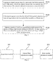
- FIG. 7 is a flowchart of an exposure time control method provided by the embodiments of the present disclosure. As shown in FIG. 7 , the exposure time control method provided by this embodiment includes the following steps.
- an original exposure time of a camera and a half-flicker period of an AC light source are acquired, wherein the original exposure time is an exposure time when exposure of the camera is adjusted to a maximum exposure threshold.
- the electronic device may directly adopt the exposure time control method provided in this embodiment to adjust the exposure time of the camera; and may also adjust the exposure time of the camera first by adjusting a number of pixel rows exposed during each exposure of the camera, and when the exposure time of the camera is still less than the half-flicker period of the AC light source after adjusting the exposure of the camera to the maximum exposure threshold (that is, there are still water ripples in a preview screen after adjusting the number of pixel rows exposed), and then adopt the exposure time control method provided in this embodiment to further adjust the exposure time of the camera, so as to improve authenticity of the screen shot by the camera on the premise of eliminating the water ripples in the preview screen.
- This situation will be explained as an example below.
- the electronic device may acquire the original exposure time of the camera and the half-flicker period of the AC light source when detecting that the exposure of the camera is the preset maximum exposure threshold; and may also to acquire the original exposure time of the camera and the half-flicker period of the AC light source when the detected exposure of the camera is the preset maximum exposure threshold and the last detected exposure does not reach the maximum exposure threshold.
- the original exposure time of the camera may be calculated based on the exposure of the camera (i.e. the maximum exposure threshold) detected at the current moment and the original light intensity entering the photosensitive element of the camera by the following formula (1).
- At S120 if the original exposure time is less than the half-flicker period, at least one target optical filter in an optical filter assembly is adjusted to a filtered state.
- the electronic device may adjust the exposure time of the camera by adjusting the number of pixel rows exposed during each exposure of the camera first. Therefore, when the acquired original exposure time is less than the half-flicker period of the AC light source, it means that the exposure time of the camera can no longer be adjusted to an integer multiple of the half-flicker period of the AC light source by means of adjusting the number of pixel rows exposed in the current light intensity. Therefore, in this embodiment, the target optical filter in the optical filter assembly may be adjusted to the filtered state in this case to reduce the intensity of light entering the photosensitive element of the camera through the target optical filter.
- the switching of the optical filter between the filtered state and the unfiltered state can be realized by sending a driving instruction to a driving device corresponding to the optical filter, for example, sending a driving instruction to the driving device, and the driving device controls a telescopic support arm to extend or contract based on the driving instruction, so as to drive the optical filter to move towards or away from a middle vertical line of the lens in a direction parallel to the lens, thereby realizing the switching of the optical filter between the filtered state and the unfiltered state.
- all the optical filters in the optical filter assembly in the filtered state may be adjusted to the unfiltered state first, after the adjustment is completed, the target optical filter is determined based on the intensity of light received by the photosensitive element and a preset range of incident light quantity, and the target filter is adjusted from the target optical filter to the filtered state. It is also possible to directly determine the target filter according to the original exposure time and the half-flicker period needed and adjust the target optical filter to the filtered state, regardless of whether the camera already has the optical filter in the filtered state.
- this embodiment can directly determine the target optical filter according to the original exposure time and the half-flicker period when the original exposure time is less than the half-flicker period of the AC light source, and adjust the target optical filter to the filtered state.
- a proportionality coefficient needing to be reduced i.e., a light intensity reduction proportionality
- a proportionality coefficient needing to be reduced i.e., a light intensity reduction proportionality
- an optical filter with a filter performance coefficient or a product of filter performance coefficients closest and no less than the light intensity reduction proportionality can be selected as the target filter from the optical filters in the optical filter assembly in the unfiltered state, then the driving instruction is sent to a target driving device corresponding to the target optical filter, and the telescopic support arm is controlled to extend to a set length by the driving device, thus adjusting the target optical filter to the filtered state.
- the adjusting the at least one target optical filter in the optical filter assembly from the a unfiltered state to the filtered state includes: calculating a light intensity reduction proportionality of the camera according to the original exposure time and the half-flicker period; determining the target optical filter according to the light intensity reduction proportionality and the light transmission performance of the optical filter; and adjusting the telescopic support arm connected with the target optical filter from an unextended state to an extended state by the target driving device corresponding to the target optical filter.
- the preset length is a distance that the optical filter moves from an original position in the unfiltered state to a position when a center of the optical filter is located on a bisector of the lens, which may be obtained by measurement in advance.
- the filter performance coefficient of the optical filter is used to characterize a degree of the light transmission performance of the optical filter.
- the light intensity reduction proportionality of the camera may be calculated according to the original exposure time and the half-flicker; an extension length of the telescopic support arm is determined according to the light intensity reduction proportionality and a light transmission change coefficient of the linearly gradient optical filter; and the telescopic support arm is controlled by the driving device to extend according to the extension length.
- the proportionality coefficient needing to be reduced i.e., a light intensity reduction proportionality
- a light transmission performance coefficient of the optical filter on the linearly gradient optical filter is determined to be location information of a target location of the light intensity reduction proportionality according to a light transmittance change coefficient of the linearly gradient optical filter, so as to determine a target extension length of the telescopic support arm when the target location is located on a bisector between the linearly gradient optical filter and the optical filter, and send a driving instruction to the driving device to control the driving device to adjust the extension length of the telescopic support arm to be the target extension length.
- the light transmittance change coefficient of the linearly gradient optical filter is configured for measuring the change of the light transmission performance coefficient of the linearly gradient optical filter when moving a unit distance.
- the target optical filter may be automatically adjusted to the filtered state; and the target optical filter may also be adjusted to the filtered state based on a triggering operation of a user. For example, when determining that the original exposure time is less than the half-flicker period of the AC light source, the user is asked whether the optical filter needs to be enabled (the preview screen with water ripples is still displayed during the inquiry process). If the user chooses not to disable (for example, clicking the "disable button" in an interface), the operation is ended. If the user chooses to enable (for example, clicking the "enable button” in the interface), the target optical filter is determined and adjusted to the filtered state.
- a number of pixel rows exposed during each exposure of the camera is determined according to light intensity information filtered by the target optical filter so as to adjust the exposure time of the camera to an integer multiple of the half-flicker period.
- the light intensity information of light entering the photosensitive element after being filtered by the optical filter may be obtained; according to the light intensity information, preset maximum exposure threshold and minimum exposure threshold of the camera during each exposure, the formula (1) is adopted to calculate the adjustable maximum exposure time and minimum exposure time of the camera under the current light intensity, so as to obtain an exposure time adjustment range of the camera under the current light intensity.
- an exposure time which is an integer multiple of the half-flicker period of the AC light source is selected as a target exposure time, and according to the target exposure time, the following formula (2) is adopted to calculate a target number of pixel rows exposed of the camera during each exposure under the current light intensity, and control pixels of the camera with a number of rows exposed during each exposure matched with the target number of pixel rows exposed, so that the exposure time of the camera can be adjusted to the integer multiple of the half-flicker period.
- Exposure time number of pixels in each row * number of pixel rows exposed * time needed to generate one pixel
- the maximum to-be-selected exposure time or the minimum to-be-selected exposure time can be selected and randomly selected as the target exposure time.
- the to-be-selected exposure time is used as the target exposure time, so that the number of pixel rows exposed during each exposure is an integer value, so as to reduce exposure control complexity.
- the light intensity of the optical filter can be adjusted in time when a light intensity of an environment in which the electronic device is located changes
- a second light intensity of light received by the photosensitive element can be periodically obtained, and when an absolute value of a difference between the second light intensity and the first light intensity corresponding to the light intensity information is greater than a preset change amplitude threshold, all the optical filter in the optical filter assembly are adjusted to the unfiltered state, and the process returns to S110.
- the following formula (3) is adopted to calculate a total light transmission performance coefficient n2 of the optical filter that needs to be adjusted to the filtered state at the current moment. If n2 ⁇ 1, it means that the light does not need to be filtered through the optical filter under the second light intensity, and all the optical filters in the optical filter assembly in the filtered state are adjusted to the unfiltered state.
- the state (for the case that the optical filter in the optical filter assembly is an optical filter with fixed light transmission performance) or the light transmission performance (for the case that the optical filter in the optical filter assembly is a linearly gradient optical filter) of the optical filter in the optical filter assembly are adjusted to adjust the total light transmission performance coefficient of the optical filter in the filtered state to n2, and the process returns to S130.
- t 1 / n 1 t 2 / n 2
- the original light intensity before filtering at the current moment may be firstly calculated according to the second light intensity and the total light transmission performance coefficient n1 of the optical filter in the filtered state at the current moment, and then the second exposure time t2 of the camera without filtering through the optical filter may be calculated according to the original light intensity.
- the exposure time control method the original exposure time when the exposure of the camera reaches the maximum exposure threshold and the half-flicker period of the AC light source are acquired, the at least one target optical filter in the optical filter assembly is adjusted to the filtered state by the optical filter adjustment module if the original exposure time is less than the half-flicker period, and the number of pixel rows exposed during each exposure of the camera is adjusted according to the light intensity information filtered by the target optical filter, so that the exposure time of the camera is adjusted to be the integer multiple of the half-flicker period of the AC light source.
- the intensity of light entering the camera photosensitive element is reduced through the optical filter, so that the situation that the water ripples in the preview screen of the camera cannot be eliminated when the light intensity of the AC light source in the environment to which the camera belongs can be avoided, and a shooting effect of the camera and photographing experience of a user can be improved.
- the embodiments of the present disclosure further provide an exposure time control apparatus.
- the apparatus may be implemented by software and/or hardware, may be generally integrated into an electronic device equipped with a camera, and typically, may be integrated into a mobile phone or a notebook computer, which controls an exposure time of a camera by executing an exposure time control method.
- FIG. 8 is a structural block diagram of the exposure time control apparatus provided by the embodiments of the present disclosure. As shown in FIG. 8 , the exposure time control apparatus includes an acquisition module 301, an optical filter adjustment module 302 and a row number adjustment module 303, wherein:
- the exposure time control apparatus provided by embodiments of the present disclosure, the original exposure time when the exposure of the camera reaches the maximum exposure threshold and the half-flicker period of the AC light source are acquired by the acquisition module, the at least one target optical filter in the optical filter assembly is adjusted to the filtered state by the optical filter adjustment module when the original exposure time is less than the half-flicker period, and the number of pixel rows exposed during each exposure of the camera is adjusted by the row number adjustment module according to the light intensity information filtered by the target optical filter, so that the exposure time of the camera is adjusted to be the integer multiple of the half-flicker period of the AC light source.
- the intensity of light entering the camera photosensitive element is reduced through the optical filter, so that the situation that the water ripples in the preview screen of the camera cannot be eliminated when the light intensity of the AC light source in the environment to which the camera belongs can be avoided, and a shooting effect of the camera and photographing experience of a user can be improved.
- the optical filter adjustment module 302 may include: a first ratio calculation unit configured for calculating a light intensity reduction proportionality of the camera according to the original exposure time and the half-flicker period when the original exposure time is less than the half-flicker period; an optical filter determination unit configured for determining the target optical filter according to the light intensity reduction proportionality and the light transmission performance of the optical filter; and a state adjustment unit configured for adjusting a telescopic support arm connected with the target optical filter from an unextended state to an extended state by a target driving device corresponding to the target optical filter.
- the optical filter adjustment module 302 may include: a second ratio calculation unit configured for calculating a light intensity reduction proportionality of the camera according to the original exposure time and the half-flicker period; a length determination unit configured for determining an extension length of a telescopic support arm according to the light intensity reduction proportionality and a light transmission change coefficient of the linearly gradient optical filter; and an extension control unit configured for controlling the telescopic support arm by the driving device to extend according to the extension length.
- the exposure time control apparatus provided by the provided by embodiments of the present disclosure can implement the exposure time control method provided by any embodiment of the present disclosure, and has corresponding functional modules and beneficial effects for implementing the exposure time control method.
- the exposure time control method provided by any embodiment of the present disclosure.
- FIG. 9 is a schematic structural diagram of an electronic device provided by the embodiments of the present disclosure.
- the electronic device includes a camera module 40, a processor 41 and a memory 42, and may also include an input device 43 and an output device 44.
- the number of the processor 41 in the electronic device may be one or more, and one processor 41 is taken as an example in FIG. 9 .
- the processor 41, the memory 42, the input device 43, and the output device 44 in the electronic device may be connected via a bus or otherwise. Bus connection is taken as an example in FIG. 9 .
- the memory 42 may be used to store software programs, computer executable programs and modules, such as program instructions/modules (for example, the acquisition module 301, the optical filter adjustment module 302 and the row number adjustment module 303 in the exposure time control apparatus) corresponding to the exposure time control method in the embodiments of the present disclosure.
- the processor 41 runs the software programs, instructions, and modules stored in the memory 42, thus performing various functional applications and data processing of the electronic device, i.e., implementing the exposure time control method above.
- the memory 42 may mainly include a program storage area and a data storage area, wherein the program storage area may store application programs required by an operating system and at least one function.
- the data storage area may store data and the like created according to the use of the terminal.
- the memory 42 may include a high-speed random access memory, and may also include a non-volatile memory, such as at least one disk memory device, a flash memory device, or other non-volatile solid storage devices.
- the memory 42 may further include memories remotely disposed with respect to the processor 41, and these remote memories may be connected to the electronic device through networks. Examples of the above networks include, but are not limited to, the Internet, enterprise intranets, local area networks, mobile communication networks, and combinations thereof.
- the input device 43 may be configured to receive input numeric or character information, and generate key signal input related to user setting and function control of the electronic device.
- the output device 44 may include a display screen and other display devices.
- the embodiments of the present disclosure further provide a storage medium containing a computer-executable instruction that, when executed by a computer processor, is configured to execute an exposure time control method:
- the computer-executable instruction is not limited to the above method operations, and may also perform related operations in the exposure time control method provided by any embodiment of the present disclosure.
- the camera module provided by the present disclosure includes the camera, the camera includes the lens and the photosensitive element, and the camera module further includes the optical filter assembly.
- the optical filter in the optical filter assembly and the lens are parallel and located on different planes, and when the optical filter is in the filtered state, the optical filter is located on one side of the photosensitive element facing the lens for reducing the intensity of light entering the photosensitive element. In this way, the situation that the water ripples in the preview screen of the camera cannot be eliminated when the light intensity of the AC light source in the environment of the electronic device to which the camera belongs is too strong can be avoided, and the shooting effect of the camera and the shooting experience of the user are improved.
Landscapes
- Engineering & Computer Science (AREA)
- Multimedia (AREA)
- Signal Processing (AREA)
- Physics & Mathematics (AREA)
- General Physics & Mathematics (AREA)
- Optics & Photonics (AREA)
- Blocking Light For Cameras (AREA)
Applications Claiming Priority (2)
| Application Number | Priority Date | Filing Date | Title |
|---|---|---|---|
| CN202010194952.7A CN111314594B (zh) | 2020-03-19 | 2020-03-19 | 摄像头模组、控制方法、装置、电子设备和存储介质 |
| PCT/CN2020/140830 WO2021184905A1 (zh) | 2020-03-19 | 2020-12-29 | 摄像头模组、控制方法、装置、电子设备和存储介质 |
Publications (2)
| Publication Number | Publication Date |
|---|---|
| EP4068748A1 true EP4068748A1 (de) | 2022-10-05 |
| EP4068748A4 EP4068748A4 (de) | 2023-05-31 |
Family
ID=71147989
Family Applications (1)
| Application Number | Title | Priority Date | Filing Date |
|---|---|---|---|
| EP20925707.0A Withdrawn EP4068748A4 (de) | 2020-03-19 | 2020-12-29 | Kameramodul, steuerungsverfahren und vorrichtung, elektronische vorrichtung und speichermedium |
Country Status (4)
| Country | Link |
|---|---|
| US (1) | US12088935B2 (de) |
| EP (1) | EP4068748A4 (de) |
| CN (1) | CN111314594B (de) |
| WO (1) | WO2021184905A1 (de) |
Families Citing this family (4)
| Publication number | Priority date | Publication date | Assignee | Title |
|---|---|---|---|---|
| CN111314594B (zh) | 2020-03-19 | 2021-11-12 | 闻泰通讯股份有限公司 | 摄像头模组、控制方法、装置、电子设备和存储介质 |
| CN114630035A (zh) * | 2022-03-21 | 2022-06-14 | 维沃移动通信有限公司 | 电子设备 |
| CN115022564A (zh) * | 2022-06-10 | 2022-09-06 | 杭州海康威视数字技术股份有限公司 | 一种摄像机 |
| CN117135470B (zh) * | 2023-02-23 | 2024-06-14 | 荣耀终端有限公司 | 拍摄方法、电子设备及存储介质 |
Family Cites Families (27)
| Publication number | Priority date | Publication date | Assignee | Title |
|---|---|---|---|---|
| JP3950707B2 (ja) * | 2002-02-22 | 2007-08-01 | キヤノン株式会社 | 光学機器 |
| JP2004112034A (ja) * | 2002-09-13 | 2004-04-08 | Canon Inc | 撮像装置 |
| CN1288494C (zh) * | 2003-12-05 | 2006-12-06 | 北京中星微电子有限公司 | 一种消除感光器件行曝光模式下闪烁现象的方法 |
| JP2006287743A (ja) * | 2005-04-01 | 2006-10-19 | Canon Inc | 情報処理装置及びその制御方法、プログラム、記憶媒体 |
| JP4900678B2 (ja) * | 2005-08-30 | 2012-03-21 | キヤノン電子株式会社 | Ndフィルタを有する絞り装置及び光学機器 |
| US7777787B2 (en) * | 2005-10-17 | 2010-08-17 | Nokia Corporation | Preventing flicker effects in video electronic devices |
| JP4354449B2 (ja) * | 2005-10-26 | 2009-10-28 | オリンパス株式会社 | 表示画像撮像方法および装置 |
| US7561190B2 (en) * | 2006-04-19 | 2009-07-14 | Nethra Imaging Inc. | Method and system to reduce flicker artifacts in captured images |
| TWI311883B (en) * | 2006-05-10 | 2009-07-01 | Novatek Microelectronics Corp | Flicker frequency detection method and device |
| JP4510783B2 (ja) * | 2006-05-23 | 2010-07-28 | キヤノン株式会社 | 光学機器 |
| CN201141966Y (zh) * | 2007-12-03 | 2008-10-29 | 陈新发 | 数字影像拍摄器用滤光片切换装置 |
| CN102368099A (zh) * | 2011-11-21 | 2012-03-07 | 沈阳仪表科学研究院 | 透射率线性渐变的中性密度滤光片 |
| JP6041503B2 (ja) * | 2012-03-13 | 2016-12-07 | 株式会社トプコン | 光量調整機構 |
| WO2014115236A1 (ja) * | 2013-01-22 | 2014-07-31 | パイオニア株式会社 | 光源モジュール、投影装置、光源モジュールの制御方法、投影装置の制御方法及びプログラム、並びに記録媒体 |
| US20190014243A1 (en) * | 2013-03-13 | 2019-01-10 | National Security Technologies, Llc | Telecentric Zoom Lens System For Optical Capture Of A Generated Event |
| CN204086641U (zh) | 2014-08-26 | 2015-01-07 | 追速科技股份有限公司 | 滤光片的调整装置 |
| US9838622B2 (en) * | 2015-03-13 | 2017-12-05 | Apple Inc. | Flicker detection using semiconductor light source |
| JP6566737B2 (ja) | 2015-06-18 | 2019-08-28 | キヤノン株式会社 | 情報処理装置、情報処理方法、プログラム |
| CN108174117B (zh) | 2015-08-10 | 2021-04-02 | Oppo广东移动通信有限公司 | 消除闪烁的方法、系统及移动终端和介质产品 |
| CN106017676A (zh) * | 2016-05-16 | 2016-10-12 | 中国电子科技集团公司第四十研究所 | 一种基于渐变滤光片的红外成像光谱测量系统 |
| US10154200B2 (en) * | 2016-05-20 | 2018-12-11 | Gentex Corporation | Imager with active exposure correction |
| JP6741533B2 (ja) * | 2016-09-26 | 2020-08-19 | キヤノン株式会社 | 撮影制御装置およびその制御方法 |
| US10237461B2 (en) * | 2017-03-01 | 2019-03-19 | Intel Corporation | Dual form factor devices having operative and complementary aligning components |
| JP7071217B2 (ja) * | 2018-05-25 | 2022-05-18 | キヤノン株式会社 | 撮像装置及びその制御方法 |
| CN208334779U (zh) * | 2018-06-21 | 2019-01-04 | 杭州海康威视数字技术股份有限公司 | 一种多滤光片切换装置及具有其的成像设备 |
| CN208548957U (zh) * | 2018-08-03 | 2019-02-26 | 杭州海康威视数字技术股份有限公司 | 一种摄像机 |
| CN111314594B (zh) | 2020-03-19 | 2021-11-12 | 闻泰通讯股份有限公司 | 摄像头模组、控制方法、装置、电子设备和存储介质 |
-
2020
- 2020-03-19 CN CN202010194952.7A patent/CN111314594B/zh active Active
- 2020-12-29 EP EP20925707.0A patent/EP4068748A4/de not_active Withdrawn
- 2020-12-29 US US17/912,069 patent/US12088935B2/en active Active
- 2020-12-29 WO PCT/CN2020/140830 patent/WO2021184905A1/zh not_active Ceased
Also Published As
| Publication number | Publication date |
|---|---|
| EP4068748A4 (de) | 2023-05-31 |
| CN111314594A (zh) | 2020-06-19 |
| US12088935B2 (en) | 2024-09-10 |
| US20230138740A1 (en) | 2023-05-04 |
| WO2021184905A1 (zh) | 2021-09-23 |
| CN111314594B (zh) | 2021-11-12 |
Similar Documents
| Publication | Publication Date | Title |
|---|---|---|
| US12088935B2 (en) | Camera module for the adjustment of light intake via an optical filter | |
| KR102310430B1 (ko) | 촬영 방법, 장치 및 디바이스 | |
| US20210400172A1 (en) | Imaging processing method and apparatus for a camera module in a night scene, an electronic device, and a storage medium | |
| EP3006984B1 (de) | Periskopartige linse und endgerätevorrichtung | |
| US8730371B2 (en) | Image processing apparatus and image processing method, and data processing apparatus and data processing method | |
| EP4460025B1 (de) | Verfahren zur steuerung der bildfrequenz beim fotografieren, elektronische vorrichtung und lesbares speichermedium | |
| US9531944B2 (en) | Focus detection apparatus and control method thereof | |
| JP6205065B2 (ja) | 撮影方法、撮影装置、プログラム及び記憶媒体 | |
| US9843728B2 (en) | Focus control apparatus, control method therefor, storage medium therefor, and image capturing apparatus | |
| US9906732B2 (en) | Image processing device, image capture device, image processing method, and program | |
| EP2995982A1 (de) | Objektivtubus, kamerasystem und bildgebungsvorrichtung | |
| US9277111B2 (en) | Image capture apparatus and control method therefor | |
| US11431903B2 (en) | Photosensitive chip, mobile terminal and photographing method | |
| JP2015096937A (ja) | 撮像装置およびその制御方法 | |
| US10136061B2 (en) | Automatic processing of automatic image capture parameter adjustment | |
| CN109937382A (zh) | 成像装置和成像方法 | |
| US20190373169A1 (en) | Image apparatus to generate a combined image, control method for controlling an apparatus to generate a combined image, and storage medium | |
| JP2012217090A (ja) | 撮像装置、撮影レンズユニット、および撮像ユニット | |
| US11622172B2 (en) | Image capture apparatus and control method for a display control of a lens brightness | |
| US11363187B2 (en) | Focusing method and apparatus applied to terminal device, and terminal device | |
| US9871973B2 (en) | Imaging apparatus and control method to capture image based on compensated exposure value | |
| US20130251356A1 (en) | Imaging device | |
| JP2019008178A (ja) | 撮像装置およびその制御方法 | |
| CN118283392A (zh) | 摄像模组及其控制方法、存储介质及电子设备 | |
| JP2014155042A (ja) | 撮像装置 |
Legal Events
| Date | Code | Title | Description |
|---|---|---|---|
| STAA | Information on the status of an ep patent application or granted ep patent |
Free format text: STATUS: THE INTERNATIONAL PUBLICATION HAS BEEN MADE |
|
| PUAI | Public reference made under article 153(3) epc to a published international application that has entered the european phase |
Free format text: ORIGINAL CODE: 0009012 |
|
| STAA | Information on the status of an ep patent application or granted ep patent |
Free format text: STATUS: REQUEST FOR EXAMINATION WAS MADE |
|
| 17P | Request for examination filed |
Effective date: 20220629 |
|
| AK | Designated contracting states |
Kind code of ref document: A1 Designated state(s): AL AT BE BG CH CY CZ DE DK EE ES FI FR GB GR HR HU IE IS IT LI LT LU LV MC MK MT NL NO PL PT RO RS SE SI SK SM TR |
|
| RIC1 | Information provided on ipc code assigned before grant |
Ipc: H04N 5/353 20110101ALI20221222BHEP Ipc: G02B 26/02 20060101ALI20221222BHEP Ipc: H04N 5/235 20060101ALI20221222BHEP Ipc: H04N 5/225 20060101AFI20221222BHEP |
|
| REG | Reference to a national code |
Ref country code: DE Ref legal event code: R079 Free format text: PREVIOUS MAIN CLASS: H04N0005225000 Ipc: H04N0023550000 |
|
| A4 | Supplementary search report drawn up and despatched |
Effective date: 20230502 |
|
| RIC1 | Information provided on ipc code assigned before grant |
Ipc: H04N 25/531 20230101ALI20230424BHEP Ipc: H04N 23/745 20230101ALI20230424BHEP Ipc: H04N 23/73 20230101ALI20230424BHEP Ipc: H04N 23/55 20230101AFI20230424BHEP |
|
| DAV | Request for validation of the european patent (deleted) | ||
| DAX | Request for extension of the european patent (deleted) | ||
| STAA | Information on the status of an ep patent application or granted ep patent |
Free format text: STATUS: THE APPLICATION IS DEEMED TO BE WITHDRAWN |
|
| 18D | Application deemed to be withdrawn |
Effective date: 20250701 |