EP4068937B1 - Variables bodenbearbeitungsgerät - Google Patents
Variables bodenbearbeitungsgerät Download PDFInfo
- Publication number
- EP4068937B1 EP4068937B1 EP20895804.1A EP20895804A EP4068937B1 EP 4068937 B1 EP4068937 B1 EP 4068937B1 EP 20895804 A EP20895804 A EP 20895804A EP 4068937 B1 EP4068937 B1 EP 4068937B1
- Authority
- EP
- European Patent Office
- Prior art keywords
- toolbar
- implement
- gangs
- gang
- vertical
- Prior art date
- Legal status (The legal status is an assumption and is not a legal conclusion. Google has not performed a legal analysis and makes no representation as to the accuracy of the status listed.)
- Active
Links
Images








Classifications
-
- A—HUMAN NECESSITIES
- A01—AGRICULTURE; FORESTRY; ANIMAL HUSBANDRY; HUNTING; TRAPPING; FISHING
- A01B—SOIL WORKING IN AGRICULTURE OR FORESTRY; PARTS, DETAILS, OR ACCESSORIES OF AGRICULTURAL MACHINES OR IMPLEMENTS, IN GENERAL
- A01B33/00—Tilling implements with rotary driven tools, e.g. in combination with fertiliser distributors or seeders, with grubbing chains, with sloping axles, with driven discs
- A01B33/02—Tilling implements with rotary driven tools, e.g. in combination with fertiliser distributors or seeders, with grubbing chains, with sloping axles, with driven discs with tools on horizontal shaft transverse to direction of travel
- A01B33/021—Tilling implements with rotary driven tools, e.g. in combination with fertiliser distributors or seeders, with grubbing chains, with sloping axles, with driven discs with tools on horizontal shaft transverse to direction of travel with rigid tools
- A01B33/024—Tilling implements with rotary driven tools, e.g. in combination with fertiliser distributors or seeders, with grubbing chains, with sloping axles, with driven discs with tools on horizontal shaft transverse to direction of travel with rigid tools with disk-like tools
-
- A—HUMAN NECESSITIES
- A01—AGRICULTURE; FORESTRY; ANIMAL HUSBANDRY; HUNTING; TRAPPING; FISHING
- A01B—SOIL WORKING IN AGRICULTURE OR FORESTRY; PARTS, DETAILS, OR ACCESSORIES OF AGRICULTURAL MACHINES OR IMPLEMENTS, IN GENERAL
- A01B33/00—Tilling implements with rotary driven tools, e.g. in combination with fertiliser distributors or seeders, with grubbing chains, with sloping axles, with driven discs
- A01B33/08—Tools; Details, e.g. adaptations of transmissions or gearings
- A01B33/12—Arrangement of the tools; Screening of the tools
-
- A—HUMAN NECESSITIES
- A01—AGRICULTURE; FORESTRY; ANIMAL HUSBANDRY; HUNTING; TRAPPING; FISHING
- A01B—SOIL WORKING IN AGRICULTURE OR FORESTRY; PARTS, DETAILS, OR ACCESSORIES OF AGRICULTURAL MACHINES OR IMPLEMENTS, IN GENERAL
- A01B63/00—Lifting or adjusting devices or arrangements for agricultural machines or implements
- A01B63/002—Devices for adjusting or regulating the position of tools or wheels
- A01B63/004—Lateral adjustment of tools
-
- A—HUMAN NECESSITIES
- A01—AGRICULTURE; FORESTRY; ANIMAL HUSBANDRY; HUNTING; TRAPPING; FISHING
- A01B—SOIL WORKING IN AGRICULTURE OR FORESTRY; PARTS, DETAILS, OR ACCESSORIES OF AGRICULTURAL MACHINES OR IMPLEMENTS, IN GENERAL
- A01B73/00—Means or arrangements to facilitate transportation of agricultural machines or implements, e.g. folding frames to reduce overall width
- A01B73/02—Folding frames
- A01B73/04—Folding frames foldable about a horizontal axis
-
- A—HUMAN NECESSITIES
- A01—AGRICULTURE; FORESTRY; ANIMAL HUSBANDRY; HUNTING; TRAPPING; FISHING
- A01B—SOIL WORKING IN AGRICULTURE OR FORESTRY; PARTS, DETAILS, OR ACCESSORIES OF AGRICULTURAL MACHINES OR IMPLEMENTS, IN GENERAL
- A01B73/00—Means or arrangements to facilitate transportation of agricultural machines or implements, e.g. folding frames to reduce overall width
- A01B73/02—Folding frames
- A01B73/06—Folding frames foldable about a vertical axis
Definitions
- This application relates to agriculture, in particular to a tillage implement for performing variable tillage.
- Tillage implements for tilling soil in a field typically comprise a frame with one or more tillage tools of one or more types mounted on the frame in a position and orientation in which the tillage tools can engage the field in order to till the soil.
- the frames are often large to provide room for mounting a plurality of tillage tools in the same transverse row on the frame to provide a broader tilling swath.
- the plurality of tillage tools in a transverse row are mounted in a gang on a common toolbar, the tool bar being mounted on the frame to facilitate mounting and exchanging large numbers of tillage tools in a shorter period of time so that the same frame can be used for different tillage operations.
- the frame also typically comprises a plurality of transverse rows of tillage tools longitudinally spaced-apart on the frame to provide greater intensity of tillage so that multiple passes with the implement over the same locations on the field are not required.
- the angles of engagement of the tillage tools with the field are usually set prior to tilling when the tillage tools are mounted on the frame, and cannot be readily changed in response to different field conditions during a tillage operation.
- multiple frame sections transversely set apart from each other may be utilized to increase the width of the frame. Utilizing multiple frame sections provides the opportunity to include an arrangement for folding frame sections into a storage position when the tillage implement is not in use to facilitate storage of the implement in a machine shop or yard. While the ability to fold frame sections into a vertical position facilitates storage of the implement and permits a limited ability to transport the implement along a roadway over short distances, vertically folded frame sections still impose difficulties in transporting fully assembled implements over long distances on roadways, particularly on roadways which pass under bridges and the like that have maximum height limitations. To overcome the maximum height limitations, manufacturers generally ship tillage implements in a disassembled state where outer frame sections are disconnected from the rest of the frame. Consequently, when the implement arrives at a customer, the implement must be assembled, which can be laborious and difficult for the customer.
- a number of tillage implements have been developed that provide the ability to rotate a gang of tillage tools through an angle of 0° to 15°, with respect to a transverse axis of the frame, to provide less or more aggressive angles of engagement of the tillage tools with the field.
- Such implements suffer from large longitudinal spacing requirements between longitudinally adjacent gangs of tillage tools, thereby requiring longer frames, which is undesirable when the frame has frame sections which are folded up for transport on a roadway.
- Such implements are required to be shipped in the disassembled state, and then reassembled by the customer.
- US4180135A discloses, according to its abstract, a hydraulic mechanism for varying the angular relationship between a pair of adjacent end-connected disc harrow gangs which uses the same power source that ordinarily is employed for raising and lowering the harrow frame structure as a power source to actuate the gang angling mechanism.
- a bell crank lever mechanism embodying a pivot shaft, trailing wheel axle arms, and a crank arm has the latter arm connected to the power source so that when the crank arm is swung in opposite fore and aft directions, the frame structure is raised or lowered.
- the gang angling mechanism embodies floating links which are connected at one end to the crank arm and which pass slidingly through the pivotal juncture between the end-connected gangs, together with removable abutment members which, when applied to the floating links in the vicinity of such junctures, engages the latter when the power source is actuated in one direction or the other and forces the juncture in a direction either to increase or decrease the angular gang relationship, depending upon whether the abutment members are applied forwardly or rearwardly of the juncture.
- CA2883425A1 discloses a tillage implement.
- US2008/110649A1 discloses a folding disk with wing stabilizer wheels.
- US2016/212928A1 discloses an agricultural tillage implement.
- US4066274A discloses a tandem folding implement.
- US2017/079198A1 discloses an agricultural vehicle pneumatic distribution system.
- a tillage implement comprising: a frame connectable to a towing vehicle, the frame comprising a plurality of elongated transverse frame elements and a plurality of elongated longitudinal frame elements connected to the plurality of elongated transverse frame elements, the frame having a horizontal longitudinal axis parallel to a direction of travel of the tillage implement and a horizontal transverse axis perpendicular to the horizontal longitudinal axis when the tillage implement is in a deployed configuration to till a field; a first gang comprising a first toolbar and a first plurality of annular harrow tools mounted on the first toolbar, the first toolbar having a first vertical toolbar plane through a length of the first toolbar, each annular harrow tool of the first plurality of annular harrow tools having a first rotating circumferential cutting edge whereby a first vertical harrow tool plane passes through two diametrically opposed points on the first circumferential cutting edge, the first toolbar pivotally mounted on the frame to be rota
- a tillage implement comprising: a frame connectable to a towing vehicle, the frame comprising a plurality of elongated transverse frame elements and a plurality of elongated longitudinal frame elements connected to the plurality of elongated transverse frame elements, the frame having a horizontal longitudinal axis parallel to a direction of travel of the tillage implement and a horizontal transverse axis perpendicular to the horizontal longitudinal axis when the tillage implement is in a deployed configuration to till a field; and, a gang comprising a toolbar and a plurality of compound angle annular harrow tools mounted on the toolbar, the toolbar pivotally mounted on the frame to be rotatable about a vertical rotation axis, each annular harrow tool of the plurality of annular harrow tools having a rotating circumferential cutting edge whereby a vertical harrow tool plane through two diametrically opposed points on the circumferential cutting edge is non-parallel to the longitudinal axis and a plane
- Variable tillage involves changing a position of a tillage tool between an aggressive tillage position where the soil is tilled to a greater extent and a non-aggressive tillage position where the soil is tilled to a lesser extent.
- aggressive or non-aggressive tillage may be required. Because soil conditions are not the same throughout a field, it is useful to be able to change the aggressiveness of the tillage tool on the fly.
- the tillage tool comprises an annular harrow tool (e.g.
- an aggressive tillage position involves angling the annular harrow so that a cutting edge of the annular harrow tool is less parallel to a direction of travel of the tillage implement
- a non-aggressive tillage position involves angling the annular harrow tool so that the cutting edge of the annular harrow tool is more parallel, preferably parallel, to a direction of travel of the tillage implement. Therefore, a tillage implement on which the angle of the annular harrow tool can be changed on the fly is useful to provide a variable tillage capability.
- longitudinally adjacent gangs of tillage tools are longitudinally spaced at a minimum distance to obtain maximum soil flow through the implement when the tillage tools are in the most aggressive tillage position in order to reduce plugging. Further, when the longitudinally adjacent gangs of tillage tools are rotated so that the tillage tools are in the least aggressive tillage position, the relative transverse position of the point at which the leading cutting edge of each of the tillage tools contacts the field shifts to provide an equidistant or nearly equidistant transverse spacing between the cutting edges of the tillage tools on the first gang in relation to the cutting edges of the tillage tools on the second gang.
- the tillage implement further comprises an actuator connected to at least one of the linkage arms of the linkage mechanism.
- the actuator may be mounted on the frame. Operation of the actuator operates the linkage mechanism. Operation of the linkage mechanism rotates the first and second toolbars about respective vertical rotation axes.
- the actuator may be controlled from the towing vehicle towing the implement, or from any other suitable location, for example remotely from an office. Any suitable actuator may be used, for example a hydraulic cylinder, a linear actuator, a pneumatic actuator, a mechanical actuator (e.g. a lever) or the like.
- the first gang comprises a first gang assembly comprising the first toolbar, a first support bar opposed to the first toolbar and at least two first support brackets rigidly connecting the first toolbar to the first support bar.
- the second gang comprises a second gang assembly comprising the second toolbar, a second support bar opposed to the second toolbar and at least two second support brackets rigidly connecting the second toolbar to the second support bar.
- the plurality of linkage arms may comprise a transversely oriented common control rod pivotally connected to the first and second gangs, for example through at least two connecting arms pivotally mounted on the control rod.
- the actuator is pivotally connected to the control rod whereby actuation of the actuator causes the first and second toolbars to rotate in opposite rotational directions about the first and second vertical rotation axes, respectively.
- the actuator is pivotally attached to the first support bar and the control rod at a common location.
- the at least two connecting arms may comprise one connecting arm pivotally connected to the control rod and the second support bar.
- the first and second gang assemblies may each comprise at least two gang assembly linkage arms.
- the gang assembly linkage arms may be pivotally connected to the first support bar and at least one of the transverse frame elements.
- the at least two connecting arms comprises two connecting arms.
- One of the connecting arms may be pivotally connected to the control rod and the first support bar.
- One of the connecting arms may be pivotally connected to the control rod and the second support bar.
- the two connecting arms pivotally may be connected to the control rod at a common location.
- the first and second support bars are each rotatably connected to the transverse frame elements at first and second pivot points, respectively, through which the first and second vertical rotation axes pass, respectively.
- the plurality of linkage arms comprises a bell crank control linkage.
- the first and second pluralities of annular harrow tools are in a least aggressive tillage position when the first and second vertical harrow tool planes are parallel to the longitudinal axis. Further, the first vertical harrow tool planes are parallel to and transversely offset equidistantly or nearly equidistantly from adjacent second vertical harrow tool planes when the first and second pluralities of annular harrow tools are in the least aggressive tillage position.
- Relative transverse positions of points at which the rotating circumferential cutting edges of the first and second pluralities of annular harrow tools first contact the field shift transversely to provide the equidistant or nearly equidistant transverse offset when the first and second gangs are rotated so that the first and second pluralities of annular harrow tools are in the least aggressive tillage position.
- each of the first and second gangs are rotatable through an angle of 16°.
- the first and second gangs each form an angle of 0° with respect to the horizontal transverse axis
- the first vertical harrow tool plane forms an angle in a range of from 0° to 16°, preferably from 8° to 16°, with respect to the horizontal longitudinal axis
- the second vertical harrow tool plane forms an angle in a range of from 0° to -16°, preferably from -8° to -16°, with respect to the horizontal longitudinal axis.
- the first vertical harrow tool plane forms an angle in a range of from 0° to 16°, preferably from 8° to 16°, with respect to a first line normal to the first vertical toolbar plane; and, the second vertical harrow tool plane forms an angle in a range of from 0° to 16°, preferably from 8° to 16° with respect to a second line normal to the second vertical toolbar plane.
- the at least one wheel comprises a plurality of wheels, for example two, three, four, five or more wheels.
- the at least one wheel is mounted longitudinally forward of both the first and second gang. Positioning the at least one wheel longitudinally forward or rearward of both the first and second gang helps shorten the frame, provides space for the linkage mechanism and permits the linkage mechanism to operate to rotate both the first and second toolbars simultaneously.
- the frame comprises at least one wing section on which the first and second gangs are mounted and a wing support.
- the wing section may be pivotally mounted on the wing support and the wing support pivotally mounted on the frame such that the wing section and the wing support are pivotable between the deployed configuration where the wing section is horizontally oriented and the first and second gangs are oriented transversely to the longitudinal axis and a stowed position where the wing section is vertically oriented and the first and second gangs are oriented parallel to the longitudinal axis.
- the at least one wing section may comprise one, two, three, four or more wing sections.
- the at least one wing section comprises a first wing section pivotally mounted on a first side of the wing support and a second wing section substantially identical to the first wing section, the second wing section pivotally mounted on the wing support on a second side transversely opposite the first side.
- the wing support may be a center section of the frame, which can also support various tillage tools, for example a further plurality of annular harrow tools.
- the further plurality of annular harrow tools may be mounted as center gangs on the center section.
- the center gangs on the center section may also be rotatable using a linkage mechanism such as the type of linkage mechanism used to rotate the first and second gangs on the at least one wing section.
- the at least one wing section comprises further gangs substantially identical to and transversely spaced-apart from the first and second gangs.
- the first and second and further gangs may be controlled by the same linkage mechanism, the linkage mechanism also disposed longitudinally between pairs of the further gangs.
- the at least one wing section may further comprise a third gang and a fourth gang substantially identical to the first gang and the second gang, respectively, and transversely spaced-apart from the first and second gangs, the third and fourth gangs connected to the linkage mechanism, the linkage mechanism disposed longitudinally between the third and fourth gangs.
- the center section may comprise further center gangs.
- the tillage implement has variable tillage capability and a shorter frame that is compact enough while remaining assembled for convenient roadway transportation when outer transverse sections (i.e. wing sections) of the frame are folded for storage and transportation.
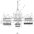
- a three-section tillage implement 10 in accordance with one embodiment of the present invention is illustrated in Fig. 1 , Fig. 2A and Fig. 2B , omitting linkage mechanisms for clarity.
- the three-section tillage implement 10 comprises a frame 12 comprising a plurality of elongated transverse frame elements 13 (only five labeled in Fig. 1 ) and a plurality of elongated longitudinal frame elements 14 (only five labeled in Fig. 1 ) rigidly connected together.
- the frame 12 has a horizontal longitudinal axis parallel to a direction of travel of the tillage implement 10 and a horizontal transverse axis perpendicular to the horizontal longitudinal axis when the tillage implement 10 is in a deployed configuration to till a field.
- Fig. 1 depicts the deployed configuration.
- the tillage implement 10 travels in a longitudinally forward direction.
- the frame 12 comprises a chassis 16.
- a pair of ground-engaging wheels 17 for supporting the chassis 16 on the ground are rotatably mounted on opposite transverse sides of the chassis 16.
- a tongue 15 of the tillage implement 10 is connected to the chassis 16 and extends in the longitudinally forward direction from the chassis 16 terminating in a hitch 19 for connecting the tillage implement 10 to a towing vehicle 1, for example a tractor or a truck.
- the frame 12 further comprises a wing support in the form of a center section 20 pivotally connected to a rear of the chassis 16 so that the center section 20 can pivot vertically about a center section pivot axis A-A, which is parallel to the horizontal transverse axis of the frame 12.
- the frame 12 further comprises a first wing section 22 and a second wing section 24.
- a proximal transverse end of the first wing section 22 is pivotally connected to a first transverse side of the center section 20 so that the first wing section 22 can pivot vertically about a first wing section pivot axis B-B , which is parallel to the horizontal longitudinal axis of the frame 12 when the tillage implement 10 is in the deployed configuration.
- a proximal transverse end of the second wing section 24 is pivotally connected to a second transverse side of the center section 20 opposite the first transverse side so that the second wing section 24 can pivot vertically about a second wing section pivot axis C-C, which is parallel to the horizontal longitudinal axis of the frame 12 when the tillage implement 10 is in the deployed configuration.
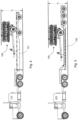
- the center section 20 and the wing sections 22, 24 are able to pivot about their respective pivot axes A-A, B-B and C-C to configure the tillage implement 10 between the deployed configuration ( Fig. 1 ) and a storage and transport configuration ( Fig. 2A and Fig. 2B ).
- the first and second wing sections 22, 24 comprise first and second wheels 21, 23, respectively, rotatably mounted thereon which support the first and second wing sections 22, 24 on the ground when the tillage implement 10 is in the deployed configuration ( Fig. 1 ).
- the first and second wheels 21, 23 are located proximate distal transverse ends of the first and second wing sections 22, 24, respectively. Further, the first and second wheels 21, 23 are situated longitudinally forward of the first and second wing sections 22, 24, respectively.
- the linkage mechanisms are used to control gangs 32 of annular harrow tools 50 (only one labeled) mounted on first transverse frame elements 13a and 13b, gangs 34 of annular harrow tools 50 (only one labeled) mounted on the second transverse frame elements 13c and 13d, and gangs of annular harrow tools 50 (only one labeled) mounted on the transverse frame elements of the center section 20.
- One or more other tillage tools may be connected (connections not shown) at a rear of the wing sections 22, 24 and/or the center section 20.
- the frame sections 20, 22, 24 are usually equipped with tillage tools in the same way to provide equivalent tillage possibilities across the width of the frame 12.
- the arrangement shown in Fig. 1 is provided to illustrate that various kinds of tillage tools may be mounted on the frame.
- the tillage implement 10 acquires a compact height profile h 1 and a compact width profile w 1 .
- a two-section tillage implement 100 is illustrated in Fig. 3A, Fig. 3B , Fig. 4 and Fig. 5 , in which the wing support is not a complete center section with its own tillage tools. Rather, the wing support comprises a narrower sub-frame 29 to which the wing sections are pivotally connected. Otherwise, the two-section tillage implement 100 is substantially the same as the three-section tillage implement 10.
- the two-section tillage implement 100 has a similar height profile h 2 to the three-section tillage implement 10, but has an even more compact width profile w 2 than the three-section tillage implement 10.
- the more compact width profile w 2 better suits the two-section tillage implement 100 for transportation on a transport trailer, for example a drop-deck flat-bed transport trailer 101 ( Fig. 4 ) or a double-drop flat-bed transport trailer 102 ( Fig. 5 ).
- Overall height profile including the transport trailer is somewhat lower for a double-drop flat-bed transport trailer 102 ( h 4 in Fig. 5 ) as compared to a drop-deck flat-bed transport trailer 101 ( h 3 in Fig. 4 ).
- transportation dimensions such as height and width
- transport regulations and physical limits e.g. hydro wires, bridges and the like
- the present tillage implement provides more compact transportation dimensions, increasing the ability to transport the fully assembled tillage implement long distances on roads through multiple regulatory jurisdictions, thereby eliminating the need for the recipient of the tillage implement to assemble the implement on arrival.
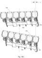
- Fig. 6A to Fig. 9B show the first and second wing sections 22, 24 transversely adjacent to each other out of context of the remainder of the tillage implement, and without the linkage mechanism.
- the first wing section 22 comprises the longitudinally adjacent and spaced-apart first transverse frame elements 13a and 13b
- the second wing section 24 comprises the longitudinally adjacent and spaced-apart second transverse frame elements 13c and 13d.
- the first transverse frame element 13a is a first forward transverse frame element and is longitudinally forward of the other first transverse frame element 13b, which is a first rearward transverse frame element.
- the second transverse frame element 13c is a second forward transverse frame element and is longitudinally forward of the other second transverse frame element 13d, which is a second rearward transverse frame element.
- Each of the first transverse frame elements 13a, 13b have the gangs 32 of annular harrow tools 50 mounted thereon.
- Each of the second transverse frame elements 13c, 13d have the gangs 34 of annular harrow tools 50 mounted thereon.
- the gangs 32 of annular harrow tools 50 comprise a first gang 32a, a second gang 32b, a third gang 32c and a fourth gang 32d, where the first and third gangs 32a, 32c are mounted on the first forward transverse frame element 13a, and the second and fourth gangs 32b, 32d are mounted on the first rearward transverse frame element 13b longitudinally in line with the first and third gangs 32a, 32c, respectively.
- the gangs 34 of annular harrow tools 50 comprise a fifth gang 34a, a sixth gang 34b, a seventh gang 34c and an eighth gang 34d, where the fifth and seventh gangs 34a, 34c are mounted on the second forward transverse frame element 13c, and the sixth and eighth gangs 34b, 34d are mounted on the second rearward transverse frame element 13d longitudinally in line with the fifth and seventh gangs 34a, 34c, respectively.
- the first and second wing sections 22, 24 are essentially identical.
- Each of the gangs 32 comprise a toolbar 38 on which the annular harrow tools 50 are mounted on rubber torsion suspensions.
- the first gang 32a comprises a first toolbar 38a.
- the second gang 32b comprises a second toolbar 38b.
- the third gang 32c comprises a third toolbar 38c.
- the fourth gang 32d comprises a fourth toolbar 38d.
- Each of the gangs 34 comprise a toolbar 39 on which the annular harrow tools 50 are mounted on rubber torsion suspensions.
- the fifth gang 34a comprises a fifth toolbar 39a.
- the sixth gang 34b comprises a sixth toolbar 39b.
- the seventh gang 34c comprises a seventh toolbar 39c.
- the eighth gang 34d comprises an eighth toolbar 39d.
- the toolbars 38, 39 are each pivotally mounted on the respective wing sections 22, 24 to be rotatable about vertical rotation axes.
- Each of the annular harrow tools 50 has a rotating circumferential cutting edge whereby a vertical harrow tool plane through two diametrically opposed points on the circumferential cutting edge is non-perpendicular to a vertical toolbar plane through a length of the toolbar 38 or 39 on which the annular harrow tool 50 is mounted.
- the vertical harrow tool planes do not rotate with respect to the vertical toolbar plane, except when the suspensions permit resilient deflection when the harrow tools 50 hit obstacles.
- the vertical harrow tool plane is shown non-perpendicular the vertical toolbar plane, the vertical harrow tool plane preferably forms an angle of from 0° to 16°, more preferably 8° to 16°, with a line normal of the vertical toolbar plane.
- a first actuator 35 connected to the first wing section 22 and to another portion of the frame 12 (e.g. the center section 20 ) can be actuated to pivot the first wing section 22 about the first wing section pivot axis B-B .
- a second actuator 36 connected to the second wing section 24 and to another portion of the frame 12 (e.g. the center section 20 ) can be actuated to pivot the second wing section 24 about the second wing section pivot axis C-C.
- the actuators 35, 36 may be any suitable actuators, for example hydraulic cylinders, linear actuators and the like.
- Fig. 6A to Fig. 9B show that the gangs 32, 34 may comprise any one of a variety of different kinds of the annular harrow tools 50, for example flat coulter blades 51 (only one labeled in Fig. 6A and Fig. 6B ), concave disc harrows 52 (only one labeled in Fig. 7A and Fig. 7B ), 13-wave coulter blades 53 (only one labeled in Fig. 8A and Fig. 8B ) and 8-wave coulter blades 54 (only one labeled in Fig. 9A and Fig. 9B ). While the gangs 32, 34 in each of the Figures are shown with the same annular harrow tool, one or more of the gangs could comprise different annular harrow tools than the other gangs.
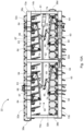
- Fig. 10A shows the first wing section 22 out of context of the remainder of the tillage implement, the first wing section 22 comprising a double link linkage mechanism 60 pivotally linked to each of the four gangs 32a, 32b, 32c, 32d through respective gang assemblies 70, the double link linkage mechanism 60 disposed longitudinally between the first toolbar 38a and the second toolbar 38b, and longitudinally between third toolbar 38c and the fourth toolbar 38d.
- the description of Fig. 10A applies similarly to the second wing section 24.
- the double link linkage mechanism 60 is operated by an actuator 61 mounted on a longitudinal frame member 14b of the first wing section 22.
- the actuator 61 is pivotally connected to the double link linkage mechanism 60. Operation of the actuator 61 operates the double link linkage mechanism 60 and the actuator 61 is controlled from the towing vehicle towing the implement.
- the actuator 61 may comprise any suitable actuator, for example a hydraulic cylinder or a linear actuator.
- Fig. 10B illustrates details of the gang assemblies 70.
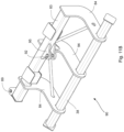
- Each gang assembly 70 comprises a rigid quadrilateral formed by the toolbar 38, an opposed support bar 63 and a pair of support brackets 74 rigidly connecting the toolbar 38 to the support bar 63.
- the support bar 63 comprises a flange 75 to which the double link linkage mechanism 60 is pivotally linked.
- the gang assembly 70 is mounted on one of the transverse frame elements 13 through a pair of gang assembly mounts 73.
- the gang assembly 70 is pivotally connected to the gang assembly mounts 73 by respective gang assembly linkage arms 64, whereby the gang assembly linkage arms 64 are portions of the double link linkage mechanism 60 and are pivotally connected to both the gang assembly mounts 73 and the support bar 63.
- the double link linkage mechanism 60 comprises a plurality of pivotally connected linkage arms.
- the plurality of linkage arms comprises the gang assembly linkage arms 64 and a transversely extending control rod 62, the control rod 62 pivotally connected to the actuator 61.
- the control rod 62 is also pivotally connected to the four gang assemblies 70 (only one labeled in Fig. 10A ), each gang assembly 70 mounting one of the four toolbars 38a, 38b, 38c, 38d to one or the other of the two transverse frame elements 13a, 13b.
- control rod 62 is directly pivotally connected to the gang assemblies 70 for the front transverse frame elements 13a and 13c at a pivot points 68 and 66, respectively, on the flanges 75 of respective support bars 63.
- the control rod 62 is indirectly pivotally connected to the gang assemblies 70 for the rear transverse frame elements 13b and 13d through connecting arms 65 at a pivot points 67 between the control rod 62 and the connecting arms 65, and each of the connecting arms 65 is directly pivotally mounted at a pivot point 69 on the support bar 63 associated with the second or fourth toolbar 38b, 38d, respectively.
- the control rod 62 is directly pivotally mounted on the support bars 63 associated with the first and third toolbars 38a, 38c, respectively.
- each support bar 63 is at a location about half way along a length of the support bar 63.
- Each of the connecting arms 65 could instead be directly pivotally mounted on one the support bars 63 associated with the first and third toolbars 38a, 38c, respectively, and the control rod 62 directly pivotally mounted on the support bar 63 associated with the second and fourth toolbars 38b, 38d, respectively.
- the actuator 61 is directly pivotally mounted on both the control rod 62 and one of the support bars 63 to which the control rod 62 is also directly pivotally mounted, the actuator 61 and the control rod 62 sharing a common pivot point 66 on the support bar 63 on which both the actuator 61 and the control rod 62 are directly mounted.
- the double link linkage mechanism 60 comprises the control rod 62, the connecting arms 65 and the gang assembly linkage arms 64. In this way, a single common control rod 62 simultaneously controls rotation of all four toolbars 38a, 38b, 38c and 38d. Further, actuation of the actuator 61 causes the first and third toolbars 38a, 38c, respectively, to rotate in opposite rotational directions about the respective vertical rotation axes than the second and fourth toolbars 38b, 38c.
- Fig. 11A shows the first wing section 22 out of context of the remainder of the tillage implement, the first wing section 22 comprising a center pivot linkage mechanism 80 pivotally linked to each of the four gangs 32a, 32b, 32c, 32d through four respective gang assemblies 90 (only one labeled in Fig. 11A ), the double link linkage mechanism 80 disposed longitudinally between the first toolbar 38a and the second toolbar 38b, and longitudinally between the third toolbar 38c and the fourth toolbar 38d.
- Fig. 11B illustrates details of the gang assemblies 90.
- Fig. 12A and Fig. 12B show detail of the center pivot linkage mechanism 80. The descriptions of Fig. 11A , Fig. 11B , Fig. 12A and Fig.
- the center pivot linkage mechanism 80 is operated by an actuator 81 mounted on a longitudinal frame member 14a of the first wing section 22.
- the actuator 81 is pivotally connected to the center pivot linkage mechanism 80. Operation of the actuator 81 operates the center linkage mechanism 80 and the actuator 81 is controlled from the towing vehicle towing the implement.
- the actuator 81 may comprise any suitable actuator, for example a hydraulic cylinder or a linear actuator.
- Each gang assembly 90 comprises a rigid quadrilateral formed by the toolbar 38, an opposed support bar 83 and a pair of outer support brackets 84 rigidly connecting the toolbar 38 to the support bar 83.
- An inner support bracket 94 also rigidly connects the toolbar 38 to the support bar 83 for added strength.
- the support bar 63 comprises a mounting flange 95 through which the gang assembly 90 is rotatably mounted to frame.
- the center pivot linkage mechanism 80 comprises a plurality of pivotally connected linkage arms.
- the plurality of linkage arms comprises a transversely extending control rod 82 and four connecting arms 85.
- the control rod 82 is pivotally connected to all four of the support bars 83 through the connecting arms 85.
- Each of the connecting arms 85 is pivotally mounted on the respective support bar 83 at pivot points 89 and pivotally mounted directly on the control rod 82 at pivot points 87. Connection of the connecting arms 85 to the support bars 83 is at a location proximate one end of each of the support bars 83.
- the actuator 81 is directly pivotally mounted on one end of control rod 82 at pivot point 86. Further, the pivot points 87 between the control rod 82 and the two connecting arms 85 connecting longitudinally aligned toolbars, i.e. toolbars 38a and 38b or toolbars 38c and 38d, are at a common location on the control rod 82.
- Each of the gang assemblies 70 are also rotatably mounted on top plates 91 through the mounting flanges 95 at pivot points 92, the pivot points 92 defining the vertical axes of rotation of the toolbars 38a, 38b, 38c and 38d.
- the top plates 91 are secured to longitudinal braces 93 attached to the transverse frame elements 13a and 13b.
- a single common control rod 82 simultaneously controls rotation of all four toolbars 38a, 38b, 38c and 38d. Further, actuation of the actuator 81 causes the first and third toolbars 38a, 38c, respectively, to rotate in opposite rotational directions about the respective vertical rotation axes than the second and fourth toolbars 38b, 38c. Furthermore, to ensure proper motion of the control rod 82, the control rod 82 is supported on both sides by roller or slider assemblies 88 (see Fig. 12A and Fig. 12B ) mounted on the longitudinal braces 93.
- Fig. 13A shows a first wing section 122 similar in construction and operation to the first wing section of Fig. 11A .
- the first wing section 122 comprises a bell crank-style center pivot linkage mechanism 180.
- Fig. 13B shows a bell crank control linkage of the bell crank-style center pivot linkage mechanism 180.
- the first wing section 122 shown in Fig. 13A comprises first longitudinally spaced-apart transverse frame elements 113a and 113b connected by first transversely spaced-apart longitudinal frame elements 114a and 114b and by transversely spaced-apart longitudinal braces 193.
- Four gangs 132a, 132b, 132c, 132d of annular harrow tools 150 are mounted on the transverse frame elements 113a and 113b.
- the center pivot linkage mechanism 180 is pivotally linked to each of the four gangs 132a, 132b, 132c, 132d through four respective gang assemblies, the center pivot linkage mechanism 180 disposed longitudinally between longitudinally spaced-apart toolbars of the gangs 132a, 132b, 132c, 132d.
- the gang assemblies are of similar construction to the gang assembly shown in Fig. 11B .
- the primary difference between the first wing section 122 of Fig. 13A and the first wing section 22 of Fig. 11A is the construction of the control linkage.
- the bell crank-style center pivot linkage mechanism 180 comprises a plurality of pivotally connected linkage arms.
- the plurality of linkage arms comprises a transversely extending control rod 182 and four arcuate connecting arms 185.
- the control rod 182 is pivotally connected to all four support bars of the gang assemblies through the connecting arms 185.
- Each of the connecting arms 185 is pivotally mounted on the respective support bar at pivot points 189 and pivotally mounted to the control rod 182 through generally triangular pivot plates 187 at pivot points 187b, 187c.
- the control rod 182 is pivotally connected to the pivot plates 187 at pivot points 187a.
- pivot points 187a, 187b, 187c on a given pivot plate 187 are spaced-apart from each other, preferably situated at the apexes of the triangular pivot plate 187. Similar to the arrangement shown in Fig. 11A , connection of the connecting arms 185 to the support bars of the gang assemblies is at a location proximate one end of each of the support bars.
- An actuator 181 is used to cause the control rod 182 to translate transversely.
- the positioning an orientation of the actuator 181 is different than in Fig. 11A because the arcuate connecting arms 185 and the triangular pivot plates 187 to which the arcuate connecting arms 185 and the control rod 182 are pivotally linked to provide for bell crank motion.
- a bell crank is a type of crank that changes motion through an angle.
- the actuator 181 can be positioned and oriented to better relate to an angle on the annular harrow tools 150, while still providing for transverse translation of the control rod 182.
- the actuator 181 is thus mounted on one of the longitudinal braces 193 at a location proximate one of the transverse frame elements, for example the transverse frame element 113b, and pivotally mounted on one of the triangular pivot plates 187 at pivot point 186.
- the actuator 181 can be mounted directly to the transverse frame element or another part of the frame.
- the actuator 181 is thereby oriented in a direction that is closer to parallel with the orientation of the plane of the annular harrow tools 150, which provides better control of the position of the gangs 132a, 132b, 132c, 132d.
- the actuator 181 thus transfers its motion through a non-zero angle into the control rod 182, the control rod 182 transferring motion to the gangs 132a, 132b, 132c, 132d to adjust the angle of the gangs 132a, 132b, 132c, 132d.
- the bell crank control linkage can be connected through a connector linkage to one or more other bell crank control linkages to permit a single actuator to control additional gangs of annular harrow tools.
- the triangular pivot plates 187 are pivotally mounted to the longitudinal braces 193 through support plates 188 pivotally mounted at pivot point 188a to the pivot plates 187 and to the support flanges 194 attached to the braces 193. Because the pivot point 186 and the pivot points 187a are offset from the pivot points 188a, actuation of the actuator 181 cause the pivot plates 187 to rotate arcuately about the pivot points 188a thereby causing the control rod 182 to translate linearly in the transverse direction to transmit motion through all of the arcuate links 185 to the gang assemblies. In this way, a single common bell crank control rod 182 simultaneously controls rotation of all four gangs in the same manner as described for the arrangement in Fig. 11A .
- Fig. 14A, Fig. 14B and Fig. 14C show the first and second wing sections 22, 24 transversely adjacent to each other out of context of the remainder of the tillage implement, and without the linkage mechanisms shown, though the wing sections 22, 24 illustrated would each comprise the center pivot linkage mechanism 80. Forward direction is indicated by a large arrow in each of Fig. 14A, Fig. 14B and Fig. 14C. Fig. 14A, Fig. 14B and Fig.
- FIG. 14C illustrate the orientations and the range of motion of the gangs 32a, 32b, 32c, 32d, 34a, 34b, 34c, 34d of the two wing sections 22, 24 as the toolbars are rotated simultaneously in opposite rotational directions about their respective vertical axes of rotation by operation of the linkage mechanisms.
- the orientations and range of motion of the gangs 32a, 32b, 32c, 32d, 34a, 34b, 34c, 34d would be similar when the wing sections 22, 24 comprise the double link linkage mechanism 60.
- long axes of the toolbars of the front gangs 32a, 32c, 34a, 34c are angled at -2° with respect to a horizontal transverse axis T-T of the implement, and annular harrow tools 50a (only one labeled) of the front gangs 32a, 32c, 34a, 34c are angled at -14° with respect to a longitudinal axis L-L of the implement.
- long axes of the toolbars of the rear gangs 32b, 32d, 34b, 34d are angled at 2° with respect to a horizontal transverse axis T-T of the implement, and the annular harrow tools 50b (only one labeled) of the rear gangs 32b, 32d, 34b, 34d are angled at 14° with respect to a horizontal longitudinal axis L-L of the implement.
- the gangs 32a, 32b, 32c, 32d, 34a, 34b, 34c, 34d are almost parallel to the transverse axis T-T and the annular harrow tools 50 are in aggressive tillage positions.
- the annular harrow tools 50 are still in aggressive tillage positions, though not quite as aggressive as in Fig. 14A , but the front gangs 32a, 32c, 34a, 34c are now longitudinally separated from the rear gangs 2b, 32d, 34b, 34d by a maximum distance at the closest separation of the gangs 32a, 32b, 32c, 32d, 34a, 34b, 34c, 34d to permit maximum soil flow through the implement.
- annular harrow tools 50 are now in a non-aggressive tillage position. Comparing Fig. 14C to Fig. 14 , it can be seen that when the annular harrow tools 50 are in a non-aggressive tillage position ( Fig. 14C ), an end 37a (only one labeled) of each of the front gangs 32a, 32c, 34a, 34c is longitudinally much closer to a corresponding end 37b of the corresponding longitudinally aligned rear gangs 32b, 32d, 34b, 34d.
- annular harrow tools 50 were in an aggressive tillage position with the gangs 32a, 32b, 32c, 32d, 34a, 34b, 34c, 34d so oriented, the implement would be subject to plugging by soil at the ends 37a, 37b because the front gangs 32a, 32c, 34a, 34c would be insufficiently longitudinally separated from the rear gangs 32b, 32d, 34b, 34d at the ends 37a, 37b of the front and rear gangs, respectively.
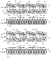
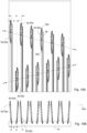
- Fig. 15A, Fig. 15B and Fig. 15C illustrate how simultaneously rotating the front and rear gangs 32a, 32b, respectively, in opposite rotational directions about their respective vertical rotation axes using the double link linkage mechanism 60 causes shifting of the relative transverse positions of the points at which rotating circumferential cutting edges of the annular harrow tools 50a (only one labeled) of the front gang 32a contact the field and the points at which the rotating circumferential cutting edges of the annular harrow tools 50b (only two labeled) of the rear gang 32b contact the field.
- Fig. 15A, Fig. 15B and Fig. 15C illustrate how simultaneously rotating the front and rear gangs 32a, 32b, respectively, in opposite rotational directions about their respective vertical rotation axes using the double link linkage mechanism 60 causes shifting of the relative transverse positions of the points at which rotating circumferential cutting edges of the annular harrow tools 50a (only one labeled) of the front gang 32a contact the field and the points at which the
- two diametrically opposed points on the circumferential cutting edge of the annular harrow tool 50 define a vertical harrow tool plane H-H (only one labeled) through the annular harrow tool 50.
- H-H vertical harrow tool plane
- J-J vertical toolbar plane
- annular harrow tools 50 are in a least aggressive tillage position where the vertical harrow tool planes H-H through two diametrically opposed points on the circumferential cutting edges of the annular harrow tools 50 are parallel to the longitudinal axis L-L of the implement.
- a given annular harrow tool 50a of the front gang 32a is transversely offset from a first transversely adjacent annular harrow tool 50b x of the rear gang 32b by a first transverse offset distance of x.
- the given annular harrow tool 50a of the front gang 32a is also transversely offset from a second transversely adjacent annular harrow tool 50b y of the rear gang 32b by a second transverse offset distance of y in the opposite transverse direction as x .
- the annular harrow tools 50b x and 50b y are the annular harrow tools on the rear gang 32b, which are the nearest transverse neighbors to the given annular harrow tool 50a on the front gang 32a.
- the first transverse offset distance x is the same as or nearly the same as the second transverse offset distance y, which means that the annular harrow tools 50 are creating longitudinal cutting paths that are equidistantly, or nearly equidistantly, transversely spaced.
- the front and rear gangs 32a, 32b, respectively are rotated so that the annular harrow tools 50 are in progressively more aggressive tillage positions (see Fig. 15B and then Fig. 15C )
- the difference between the first transverse offset distance x and the second transverse offset distance y changes, indicating that the points at which the rotating circumferential cutting edges of the annular harrow tools of the front and rear gangs contact the field are shifting transversely relative to each other.
- This shifting permits the annular harrow tools 50a of the front gang 32a to throw soil back to the annular harrow tools 50b of the rear gang 32b for more efficient and effective tilling. Further, as previously mentioned, rotating the front and rear gangs 32a, 32b, respectively, so that the annular harrow tools 50 are in more aggressive tillage positions increases the longitudinal separation of the gangs 32a, 32b at the closest separation of the gangs 32a, 32b, which provides maximum soil flow and helps prevent plugging of the implement.
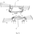
- Fig. 16 depicts the location in space of virtual vertical rotation axes P1 and P2 of the toolbars 38a and 38b, respectively, as the toolbars 38a and 38b are rotated in opposite rotation directions by the double link linkage mechanism 60.
- Fig. 16 is a top view with the forward direction being toward the top of the Figure. Fig.
- FIG. 16 shows that the virtual rotation axis P1 of the front toolbar 38a is forward of the front toolbar 38a, and that the pivot point 68 where the side linkage arm 63 is connected to the control rod (not shown in Fig. 16 ) translates transversely as the front toolbar 38a is rotated about the rotation axis P1.
- the virtual rotation axes P2 of the rear toolbar 38b is rearward of the rear toolbar 38b, and the pivot point 69 where the side linkage arm 63 is connected to the control rod (not shown in Fig. 16 ) translates transversely as the rear toolbar 38b is rotated about the rotation axis P2.
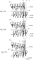
- Fig. 17, Fig. 17B and Fig. 17C illustrate how simultaneously rotating the front and rear gangs 32c, 32d, respectively, in opposite rotational directions about their respective vertical rotation axes using the center pivot linkage mechanism 80 causes shifting of the relative transverse positions of the points at which rotating circumferential cutting edges of the annular harrow tools 50a (only one labeled) of the front gang 32a contact the field and the points at which the rotating circumferential cutting edges of the annular harrow tools 50b (only two labeled) of the rear gang 32b contact the field.
- Fig. 17A shows the annular harrow tools 50 in a less aggressive tillage position, with the aggressiveness of the tillage position of the annular harrow tools 50 increasing through Fig.
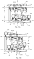
- the annular harrow tools 50 (only one labeled on each gang) are in an aggressive tillage position angled away from the longitudinal axis L-L of the tillage implement, while when the annular harrow tools 50 are in a least aggressive tillage position parallel to the longitudinal axis L-L ( Fig. 18B ), the gangs 34a, 34b are angled away (angle f 2 ) from the transverse axis T-T.
- Fig. 18C shows the front gang 34a from Fig. 18A and Fig. 18B with the annular harrow tools 50a (only one labeled) shown in an aggressive tillage position (upper) and a non-aggressive tillage position (lower) illustrating how relative transverse positions of points at which the cutting edges of the annular harrow tools 50a first contact the field shift transversely by an amount z when the gang 34a is rotated 12° between the aggressive tillage position (upper) and the non-aggressive tillage position (lower).
- the real pivot point 92a through which the vertical rotation axis passed does not shift transversely when the gang 34a is rotated about the vertical rotation axis.
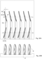
- FIG. 19A and Fig. 19B depict how annular harrow tools 50a (only three labeled) in front gangs and annular harrow tools 50b (only one labeled) in rear gangs are arranged when the annular harrow tools 50 are in a least aggressive tillage position and the vertical toolbar planes J-J of the gangs are angled away from the transverse axis of the tillage implement.
- diametrically opposed points 55a, 55b (only one each labeled) on the circumferential cutting edge 56 (only one labeled) of the annular harrow tools 50 define a vertical harrow tool plane that is parallel to the longitudinal axis of the implement, which is parallel to the direction of motion of the implement.
- Soil disturbance when the annular harrow tools 50 are in the least aggressive tillage position is shown in Fig. 19B , which shows that in the least aggressive position, the annular harrow tools 50 slice to reduce size of residue in soil 57, but provide minimal tillage.
- a transverse distance b between the cutting points of adjacent annular harrow tools 50 on the same gang is the same from tool-to-tool, and a transverse distance a between the cutting points of adjacent annular harrow tools 50 on different gangs is about half of the distance b, which results in cutting lines that transversely essentially equidistant apart by the distance a.
- longitudinal separation between the vertical toolbar planes J-J of the front and rear gangs is small at one end of the gangs and large at the other end. The small longitudinal separation at the one end does not affect performance because the annular harrow tools 50 only minimally till the soil 57 so large amounts of soil flow through the implement are not required and no plugging at the end with smaller separation of the gangs will occur.
- Fig. 20A and Fig. 20B depict how annular harrow tools 50a (only one labeled) in the front gangs and annular harrow tools 50b (only one labeled) in rear gangs are arranged when the annular harrow tools 50 are in a most aggressive tillage position and the vertical toolbar planes J-J of the gangs are parallel or almost parallel with the transverse axis of the tillage implement.
- diametrically opposed points 55a, 55b (only one each labeled) on the circumferential cutting edge 56 (only one labeled) of the annular harrow tools 50 define a vertical harrow tool plane that is angled away from the longitudinal axis of the implement.
- Fig. 20B Soil disturbance when the annular harrow tools 50 are in the most aggressive tillage position is shown in Fig. 20B , which shows that in the most aggressive position, the annular harrow tools 50 create full shear across the soil 57 fully disturbing the soil 57 for maximum tillage. Further a transverse distance c between the cutting points of adjacent annular harrow tools 50 on different gangs is small, while the transverse distance between the cutting points of adjacent annular harrow tools 50 on the same gang is large. Furthermore, longitudinal separation between the vertical toolbar planes J-J of the front and rear gangs is the same along the lengths of the gangs, and is large enough to permit the highly tilled soil 57 to flow through the implement without plugging the implement.
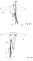
- FIG. 21A, Fig. 21B , Fig. 22A and Fig. 22B illustrate annular harrow tools 50 mounted at compound angles on a toolbar 38 illustrating that the gangs may be arranged similarly using annular harrow tools 50 mounted at compound angles.
- Fig. 21A and Fig. 21B depicts a single angle annular harrow tool 50 mounted on the toolbar 38 at compound angles where angle s is an angle relation between a vertical plane G-G through a center C of the annular harrow tool 50 and the direction of travel of the implement (i.e.
- Fig. 22A and Fig. 22B depict a gang 32 of annular harrow tools 50 (only one labeled) mounted on the toolbar 38 illustrating the angle s (only one labeled) that the compound angle mounted annular harrow tools 50 make with respect to the longitudinal axis L-L of the tillage implement ( Fig. 22A ), and illustrating the angle e that the compound angle mounted harrow tools 50 make with respect to the vertical axis CL of the tillage implement
Landscapes
- Life Sciences & Earth Sciences (AREA)
- Engineering & Computer Science (AREA)
- Mechanical Engineering (AREA)
- Soil Sciences (AREA)
- Environmental Sciences (AREA)
- Soil Working Implements (AREA)
- Agricultural Machines (AREA)
Claims (17)
- Ein Bodenbearbeitungsgerät (10, 100) umfassend:einen Rahmen (12), der mit einem Zugfahrzeug (1) verbunden werden kann, wobei der Rahmen eine Vielzahl von länglichen Querrahmenelementen (13, 13a, 13b, 13c, 13d) und eine Vielzahl von länglichen Längsrahmenelementen (14, 14a, 14b, 114a, 114b) umfasst, die mit der Vielzahl von länglichen Querrahmenelementen (13, 13a, 13b, 13c, 13d) verbunden sind, wobei der Rahmen (12) eine horizontale Längsachse parallel zu einer Fahrtrichtung des Bodenbearbeitungsgeräts (10, 100) und eine horizontale Querachse senkrecht zu der horizontalen Längsachse hat, wenn das Bodenbearbeitungsgerät (10, 100) in einer ausgefahrenen Konfiguration zum Bearbeiten eines Feldes ist;eine erste Werkzeuggruppe (32a, 132a) umfassend eine erste Werkzeugleiste (38a) und eine erste Vielzahl von ringförmigen Eggenwerkzeugen (50, 50a, 150), die an der ersten Werkzeugleiste (38a) montiert sind, wobei die erste Werkzeugleiste (38a) eine erste vertikale Werkzeugleistenebene durch eine Länge der ersten Werkzeugleiste (38a) hat, wobei jedes ringförmige Eggenwerkzeug (50, 50a, 150) der ersten Vielzahl von ringförmigen Eggenwerkzeugen eine erste rotierende Umfangsschneidekante (56) hat, wodurch eine erste vertikale Eggenwerkzeugebene durch zwei diametral gegenüberliegende Punkte (55a, 55b) an der ersten Umfangsschneidekante (56) verläuft, wobei die erste Werkzeugleiste (38a) schwenkbar an dem Rahmen (12) montiert ist, um um eine erste vertikale Drehachse drehbar zu sein;eine zweite Werkzeuggruppe (32b, 132b) umfassend eine zweite Werkzeugleiste (38b) und eine zweite Vielzahl von ringförmigen Eggenwerkzeugen (50, 50b, 50bx, 50by, 150), die an der zweiten Werkzeugleiste (38b) montiert sind, wobei die zweite Werkzeugleiste (38b) eine zweite vertikale Werkzeugleistenebene durch eine Länge der zweiten Werkzeugleiste hat, wobei jedes ringförmige Eggenwerkzeug (50, 50b, 50bx, 50by, 150) der zweiten Vielzahl von ringförmigen Eggenwerkzeugen eine zweite rotierende Umfangsschneidekante (56) hat, wodurch eine zweite vertikale Eggenwerkzeugebene durch zwei diametral gegenüberliegende Punkte (55a, 55b) an der zweiten Umfangsschneidekante (56) verläuft, wobei die zweite Werkzeugleiste (38b) schwenkbar an dem Rahmen (12) montiert ist, um um eine zweite vertikale Drehachse drehbar zu sein;einen Verbindungsmechanismus (60, 80, 180), der in Längsrichtung zwischen der ersten und der zweiten Werkzeugleiste angeordnet ist, wobei der Verbindungsmechanismus (60, 80, 180) eine Vielzahl von schwenkbar verbundenen Verbindungsarmen (64) umfasst, wobei die erste und die zweite Werkzeugleiste jeweils schwenkbar mit dem Verbindungsmechanismus (60, 80, 180) verbunden sind, wobei der Verbindungsmechanismus konfiguriert ist, um gleichzeitig die erste Werkzeugleiste (38a) um die erste vertikale Drehachse zu drehen und die zweite Werkzeugleiste (38b) um die zweite vertikale Drehachse in einer entgegengesetzten Drehrichtung in Bezug auf die erste Werkzeugleiste (38a) während des Betriebs des Verbindungsmechanismus zu drehen;dadurch gekennzeichnet, dass Folgendes bereitgestellt wirdmindestens ein Rad (17, 21, 23) zum Stützen des Rahmens (12) auf dem Feld, wobei das mindestens eine Rad (17, 21, 23) in Längsrichtung vor sowohl der ersten als auch der zweiten Werkzeuggruppe oder in Längsrichtung hinter sowohl der ersten als auch der zweiten Werkzeuggruppe an dem Rahmen montiert ist.
- Das Gerät (10, 100) von Anspruch 1, ferner umfassend einen Aktor (35, 36, 61, 81, 181), der an dem Rahmen (12) montiert und mit mindestens einem der Verbindungsarme (64) des Verbindungsmechanismus (60, 80, 180) verbunden ist, wobei der Betrieb des Aktors (35, 36, 61, 81, 181) den Verbindungsmechanismus (60, 80, 180) betätigt und der Aktor (35, 36, 61, 81, 181) von dem Zugfahrzeug (1) gesteuert wird, das das Gerät (10, 100) zieht.
- Das Gerät (10, 100) von Anspruch 2, wobei der Aktor (35, 36, 61, 81, 181) einen Hydraulikzylinder oder einen Linearaktor umfasst.
- Das Gerät (10, 100) von Anspruch 2 oder Anspruch 3, wobei:die erste Werkzeuggruppe (32a) eine erste Werkzeuggruppenanordnung (70, 90) umfasst, die die erste Werkzeugleiste (38a), eine erste Stützstange, die der ersten Werkzeugleiste (38a) gegenüberliegt, und mindestens zwei erste Stützhalterungen (74) umfasst, die die erste Werkzeugleiste (38a) starr mit der ersten Stützstange verbinden;die zweite Werkzeuggruppe (32b) eine zweite Werkzeuggruppenanordnung (70, 90) umfasst, die die zweite Werkzeugleiste (38b), eine zweite Stützstange, die der zweiten Werkzeugleiste (38b) gegenüberliegt, und mindestens zwei zweite Stützhalterungen (74) umfasst, die die zweite Werkzeugleiste (38b) starr mit der zweiten Stützstange verbinden;die Vielzahl von Verbindungsarmen (64) eine quer ausgerichtete gemeinsame Steuerstange (62, 82, 182) umfasst, die durch mindestens zwei Verbindungsarme (65, 85, 185), die an der Steuerstange (62) schwenkbar angebracht sind, schwenkbar mit der ersten und zweiten Werkzeuggruppe verbunden ist; undder Aktor (35, 36, 61, 81, 181) schwenkbar mit der Steuerstange (62) verbunden ist, wodurch eine Betätigung des Aktors bewirkt, dass sich die erste und die zweite Werkzeugleiste (38a, 38b) in entgegengesetzte Drehrichtungen um die erste und die zweite vertikale Drehachse drehen.
- Das Gerät (10, 100) von Anspruch 4, wobei:der Aktor (35, 36, 61, 81, 181) schwenkbar an der ersten Stützstange und der Steuerstange (62) an einer gemeinsamen Stelle (66) angebracht ist;die mindestens zwei Verbindungsarme (65, 85, 185) einen Verbindungsarm (65, 85, 185) umfassen, der schwenkbar mit der Steuerstange (62, 82, 182) und der zweiten Stützstange verbunden ist; unddie erste und die zweite Werkzeuggruppenbaugruppe (70) jeweils mindestens zwei Werkzeuggruppenanordnungsverbindungsarme (64) umfassen, wobei jeder der Werkzeuggruppenanordnungsarme schwenkbar mit der ersten Stützstange und mindestens einem der Querrahmenelemente (13, 13a, 13b, 13c, 13d) verbunden ist.
- Das Gerät (10, 100) von Anspruch 4, wobei:die mindestens zwei Verbindungsarme (65, 85, 185) zwei Verbindungsarme (65, 85, 185) umfassen, wobei einer der Verbindungsarme (65, 85, 185) schwenkbar mit der Steuerstange (62, 82, 182) und der ersten Stützstange verbunden ist und einer der Verbindungsarme (65, 85, 185) schwenkbar mit der Steuerstange (62, 82, 182) und der zweiten Stützstange verbunden ist, wobei die zwei Verbindungsarme (65, 85, 185) an einer gemeinsamen Stelle schwenkbar mit der Steuerstange (62, 82, 182) verbunden sind; unddie erste und die zweite Stützstange jeweils an einem ersten und einem zweiten Drehpunkt, durch welche die erste und die zweite vertikale Drehachse verlaufen, drehbar mit den Querrahmenelementen (13, 13a, 13b, 13c, 13d) verbunden sind.
- Das Gerät (10, 100) von Anspruch 4, wobei die Vielzahl von Verbindungsarmen (64) ein Winkelhebelsteuergestänge umfasst.
- Das Gerät (10, 100) von einem der Ansprüche 1 bis 7, wobei das mindestens eine Rad (17, 21, 23) eine Vielzahl von Rädern umfasst, die in Längsrichtung vor sowohl der ersten als auch der zweiten Werkzeuggruppe (32a, 32b) montiert sind.
- Das Gerät (10, 100) von einem der Ansprüche 1 bis 8, wobei:die erste und die zweite Vielzahl von ringförmigen Eggenwerkzeugen (50, 50a, 50b, 50bx, 50by, 150) in einer am wenigsten aggressiven Bodenbearbeitungsposition sind, wenn die erste und die zweite vertikale Eggenwerkzeugebenen parallel zu der Längsachse sind;die ersten vertikalen Eggenwerkzeugebenen parallel zu und quer äquidistant oder nahezu äquidistant von benachbarten zweiten vertikalen Eggenwerkzeugebenen versetzt sind, wenn die erste und die zweite Vielzahl von ringförmigen Eggenwerkzeugen (50, 50a, 50b, 50bx, 50by, 150) in der am wenigsten aggressiven Bodenbearbeitungsposition sind; undrelative Querpositionen von Punkten, an denen die rotierenden Umfangsschneidkanten (56) der ersten und der zweiten Vielzahl von ringförmigen Eggenwerkzeugen zuerst das Feld berühren, quer verschoben werden, um den äquidistanten oder nahezu äquidistanten Querversatz bereitzustellen, wenn die erste und die zweite Werkzeuggruppe (32a, 32b) gedreht werden, so dass die erste und die zweite Vielzahl von ringförmigen Eggenwerkzeugen in der am wenigsten aggressiven Bodenbearbeitungsposition sind.
- Das Gerät (10, 100) von einem der Ansprüche 1 bis 9, wobei jede der ersten und der zweiten Werkzeuggruppe um einen Winkel von 16° drehbar ist.
- Das Gerät (10, 100) von einem der Ansprüche 1 bis 10, wobei, wenn die erste und die zweite Werkzeuggruppe (32a, 32b) jeweils einen Winkel von 0° in Bezug auf die horizontale Querachse bilden, die erste vertikale Eggenwerkzeugebene einen Winkel in einem Bereich von 0° bis 16° in Bezug auf die horizontale Längsachse bildet und die zweite vertikale Eggenwerkzeugebene einen Winkel in einem Bereich von 0° bis -16° in Bezug auf die horizontale Längsachse bildet.
- Das Gerät (10, 100) von einem der Ansprüche 1 bis 10, wobei, wenn die erste und die zweite Werkzeuggruppe (32a, 32b) jeweils einen Winkel von 0° in Bezug auf die horizontale Querachse bilden, die erste vertikale Eggenwerkzeugebene einen Winkel in einem Bereich von 8° bis 16° in Bezug auf die horizontale Längsachse bildet und die zweite vertikale Eggenwerkzeugebene einen Winkel in einem Bereich von -8° bis -16° in Bezug auf die horizontale Längsachse bildet.
- Das Gerät (10, 100) von einem der Ansprüche 1 bis 10, wobei: die erste vertikale Eggenwerkzeugebene einen Winkel in einem Bereich von 0° bis 16° in Bezug auf eine erste Linie senkrecht zu der ersten vertikalen Werkzeugleistenebene bildet; und die zweite vertikale Eggenwerkzeugebene einen Winkel in einem Bereich von 0° bis 16° in Bezug auf eine zweite Linie senkrecht zu der zweiten vertikalen Werkzeugleistenebene bildet.
- Das Gerät (10, 100) von einem der Ansprüche 1 bis 10, wobei: die erste vertikale Eggenwerkzeugebene einen Winkel in einem Bereich von 8° bis 16° in Bezug auf eine erste Linie senkrecht zu der ersten vertikalen Werkzeugleistenebene bildet; und die zweite vertikale Eggenwerkzeugebene einen Winkel in einem Bereich von 8° bis 16° in Bezug auf eine zweite Linie senkrecht zu der zweiten vertikalen Werkzeugleistenebene bildet.
- Das Gerät (10, 100) von einem der Ansprüche 1 bis 14, wobei der Rahmen (12) einen Flügelabschnitt (22, 24, 122), an dem die erste und die zweite Werkzeuggruppe (32a, 32b) angebracht sind, und eine Flügelstütze umfasst, wobei der Flügelabschnitt (22, 24, 122) schwenkbar an der Flügelstütze angebracht ist und die Flügelstütze schwenkbar an dem Rahmen (12) angebracht ist, so dass der Flügelabschnitt (22, 24, 122) und die Flügelstütze zwischen der ausgefahrenen Konfiguration, in der der Flügelabschnitt horizontal ausgerichtet ist und die erste und die zweite Werkzeuggruppe quer zu der Längsachse ausgerichtet sind, und einer verstauten Position, in der der Flügelabschnitt vertikal ausgerichtet ist und die erste und die zweite Werkzeuggruppe parallel zu der Längsachse ausgerichtet sind, schwenkbar sind.
- Das Gerät (10, 100) von Anspruch 15, wobei der Flügelabschnitt ferner eine dritte Werkzeuggruppe (32c) und eine vierte Werkzeuggruppe (32d) umfasst, die im Wesentlichen mit der ersten Werkzeuggruppe (32a) und der zweiten Werkzeuggruppe (32b) identisch sind und in Querrichtung von der ersten und der zweiten Werkzeuggruppe beabstandet sind, wobei die dritte und die vierte Werkzeuggruppe mit dem Verbindungsmechanismus (60, 80, 180) verbunden sind, wobei der Verbindungsmechanismus (60, 80, 180) in Längsrichtung zwischen der dritten und der vierten Werkzeuggruppe angeordnet ist.
- Das Gerät (10, 100) von Anspruch 15 oder Anspruch 16, wobei die Flügelstütze ein Mittelabschnitt (20) des Rahmens ist, der Flügelabschnitt ein erster Flügelabschnitt (22, 122) ist, der schwenkbar an einer ersten Seite des Mittelabschnitts (20) montiert ist, und wobei der Rahmen ferner einen zweiten Flügelabschnitt (24) umfasst, der im Wesentlichen mit dem ersten Flügelabschnitt identisch ist, wobei der zweite Flügelabschnitt (24) schwenkbar an dem Mittelabschnitt an einer zweiten Seite quer gegenüber der ersten Seite montiert ist.
Applications Claiming Priority (2)
| Application Number | Priority Date | Filing Date | Title |
|---|---|---|---|
| US201962943863P | 2019-12-05 | 2019-12-05 | |
| PCT/CA2020/051633 WO2021108898A1 (en) | 2019-12-05 | 2020-11-27 | Variable tillage implement |
Publications (4)
| Publication Number | Publication Date |
|---|---|
| EP4068937A1 EP4068937A1 (de) | 2022-10-12 |
| EP4068937A4 EP4068937A4 (de) | 2024-01-03 |
| EP4068937C0 EP4068937C0 (de) | 2025-06-18 |
| EP4068937B1 true EP4068937B1 (de) | 2025-06-18 |
Family
ID=76221232
Family Applications (1)
| Application Number | Title | Priority Date | Filing Date |
|---|---|---|---|
| EP20895804.1A Active EP4068937B1 (de) | 2019-12-05 | 2020-11-27 | Variables bodenbearbeitungsgerät |
Country Status (8)
| Country | Link |
|---|---|
| US (1) | US20220408625A1 (de) |
| EP (1) | EP4068937B1 (de) |
| AU (1) | AU2020396059B2 (de) |
| BR (1) | BR112022010939A2 (de) |
| CA (1) | CA3158986A1 (de) |
| HU (1) | HUE072370T2 (de) |
| PL (1) | PL4068937T3 (de) |
| WO (1) | WO2021108898A1 (de) |
Family Cites Families (33)
| Publication number | Priority date | Publication date | Assignee | Title |
|---|---|---|---|---|
| US1919080A (en) * | 1931-01-22 | 1933-07-18 | Brenneis Mfg Company | Offset disk harrow |
| US2679791A (en) * | 1949-08-24 | 1954-06-01 | Fletcher B Carney | Disk plow and mounting therefor |
| US2648184A (en) * | 1951-10-09 | 1953-08-11 | William Payne | Disk harrow |
| US3132700A (en) * | 1961-07-03 | 1964-05-12 | Richardson Mfg Inc | Frame for agricultural implement |
| US3439750A (en) * | 1965-10-05 | 1969-04-22 | Alexander Mfg Co | Automatic-releasing cable control for harrow |
| US3460630A (en) * | 1965-12-16 | 1969-08-12 | Massey Ferguson Inc | Transport attachment for implements |
| US3545033A (en) * | 1968-04-16 | 1970-12-08 | Chester F Couser | Implement hinge |
| US3643743A (en) * | 1969-12-29 | 1972-02-22 | Int Harvester Co | Mechanism for opening and closing an offset disk harrow |
| US3757871A (en) * | 1972-01-26 | 1973-09-11 | Deere & Co | Minimum tillage agricultural implement |
| US3797580A (en) * | 1972-02-28 | 1974-03-19 | Deere & Co | Foldable agricultural implement |
| US4034623A (en) * | 1974-02-13 | 1977-07-12 | Ideal Industries, Inc. | Folding mechanism for hinged implement frame extensions |
| US4180135A (en) | 1975-07-07 | 1979-12-25 | International Harvester Company | Hydraulic angling mechanism for disc harrow gangs |
| US4061195A (en) * | 1976-01-30 | 1977-12-06 | Austin Industries, Inc. | Lock and lift mechanism for a foldable implement |
| US4056149A (en) * | 1976-03-08 | 1977-11-01 | Deere & Company | Rearwardly folding implement |
| US4066274A (en) * | 1976-07-29 | 1978-01-03 | Hesston Corporation | Tandem folding implement |
| US4328869A (en) * | 1981-02-17 | 1982-05-11 | International Harvester Company | Implement with wing lift including toggle links and roller |
| US4423789A (en) * | 1982-02-01 | 1984-01-03 | Chromalloy American Corporation | Offset disc harrow |
| US4479554A (en) * | 1982-06-17 | 1984-10-30 | J. B. Mccoy Construction Co. | Method and apparatus for mounting and lifting implement extension wings |
| US4986367A (en) * | 1989-12-04 | 1991-01-22 | Kinze Manufacturing, Inc. | Folding row marker |
| US6935435B1 (en) * | 2003-11-21 | 2005-08-30 | John E. Shenk | Positionable cultivating apparatus for raised bed crops |
| FR2865102B1 (fr) * | 2004-01-19 | 2006-04-07 | Michel Evin | Machine de travail du sol, du type dechaumeuse |
| WO2005099428A1 (en) * | 2004-04-14 | 2005-10-27 | Phoenix Rotary Equipment Ltd. | Harrow frame and harrow formed therewith |
| US20080110649A1 (en) | 2006-10-27 | 2008-05-15 | Deere And Company | Folding disk with wing stabilizer wheels |
| CA2585274C (en) * | 2007-04-10 | 2011-07-19 | Stanley J. Boyko | Rotary mower over-center self-locking wing lift |
| US20110284253A1 (en) * | 2010-05-21 | 2011-11-24 | Donald Stevenson | Disc cultivator |
| US8534374B2 (en) * | 2011-08-26 | 2013-09-17 | Great Plains Manufacturing, Inc. | Tillage implement with adjustable gang angle |
| US9474197B2 (en) * | 2013-03-15 | 2016-10-25 | Mcfarlane Manufacturing Co., Inc. | Universal custom agricultural field preparation implement |
| US10285323B2 (en) | 2013-11-13 | 2019-05-14 | Cnh Industrial America Llc | Agricultural tillage implement fold sequence control |
| CA2833682A1 (en) * | 2013-11-20 | 2015-05-20 | Schulte Industries Ltd. | Disc implement with angle adjustment |
| CA2883425C (en) * | 2015-02-27 | 2021-12-07 | Johan Redekop | Tillage implement |
| US9668399B2 (en) * | 2015-03-10 | 2017-06-06 | Andrew R. Gates | Dynamically adaptive soil conditioning system |
| US9969569B2 (en) | 2015-09-22 | 2018-05-15 | Deere & Company | Agricultural vehicle pneumatic distribution system |
| US10194573B2 (en) * | 2015-09-23 | 2019-02-05 | Deere & Company | Anti-tangle harrow attachment |
-
2020
- 2020-11-27 PL PL20895804.1T patent/PL4068937T3/pl unknown
- 2020-11-27 WO PCT/CA2020/051633 patent/WO2021108898A1/en not_active Ceased
- 2020-11-27 AU AU2020396059A patent/AU2020396059B2/en active Active
- 2020-11-27 EP EP20895804.1A patent/EP4068937B1/de active Active
- 2020-11-27 HU HUE20895804A patent/HUE072370T2/hu unknown
- 2020-11-27 US US17/778,174 patent/US20220408625A1/en active Pending
- 2020-11-27 BR BR112022010939A patent/BR112022010939A2/pt unknown
- 2020-11-27 CA CA3158986A patent/CA3158986A1/en active Pending
Also Published As
| Publication number | Publication date |
|---|---|
| HUE072370T2 (hu) | 2025-11-28 |
| CA3158986A1 (en) | 2021-06-10 |
| EP4068937A1 (de) | 2022-10-12 |
| WO2021108898A1 (en) | 2021-06-10 |
| EP4068937C0 (de) | 2025-06-18 |
| AU2020396059B2 (en) | 2026-03-12 |
| WO2021108898A9 (en) | 2021-12-02 |
| US20220408625A1 (en) | 2022-12-29 |
| AU2020396059A1 (en) | 2022-06-02 |
| EP4068937A4 (de) | 2024-01-03 |
| BR112022010939A2 (pt) | 2022-09-06 |
| PL4068937T3 (pl) | 2025-09-01 |
Similar Documents
| Publication | Publication Date | Title |
|---|---|---|
| AU2013209328B2 (en) | Rear folding toolbar implement | |
| US8118110B2 (en) | Agricultural implements with hinged and floating wings | |
| US7861795B2 (en) | Implement transport | |
| US9072214B2 (en) | Steerable agricultural implement with adaptable wheel spacing | |
| CA2723213C (en) | Foldable farm implement | |
| US8215413B2 (en) | Boom stabilization method for narrow transport implement | |
| US20150156945A1 (en) | Flexible wing sections for a field cultivator | |
| AU766963B2 (en) | Agricultural implement lift wheel structure | |
| US10888044B2 (en) | Pivoting implement frame | |
| US5158145A (en) | Cultivator | |
| CA2119294C (en) | Harrow | |
| US20150020718A1 (en) | Folding implement for the preparation of seed beds | |
| US9706699B2 (en) | Draft linkage configuration | |
| US20090032274A1 (en) | Folding furrow chopper | |
| US10561053B1 (en) | Frame assembly and actuator arrangement for agricultural imglements | |
| AU2020396059B2 (en) | Variable tillage implement | |
| CA3186142C (en) | Flexible cultivator implement | |
| US20150163989A1 (en) | Agricultural implements with hinged and floating wings | |
| CA3049213A1 (en) | Frame and leveling assembly for agricultural implement | |
| SE0850181A1 (sv) | Lantbruksmaskin med variabelt radavstånd | |
| EA043763B1 (ru) | Почвообрабатывающее орудие |
Legal Events
| Date | Code | Title | Description |
|---|---|---|---|
| STAA | Information on the status of an ep patent application or granted ep patent |
Free format text: STATUS: THE INTERNATIONAL PUBLICATION HAS BEEN MADE |
|
| PUAI | Public reference made under article 153(3) epc to a published international application that has entered the european phase |
Free format text: ORIGINAL CODE: 0009012 |
|
| STAA | Information on the status of an ep patent application or granted ep patent |
Free format text: STATUS: REQUEST FOR EXAMINATION WAS MADE |
|
| 17P | Request for examination filed |
Effective date: 20220705 |
|
| AK | Designated contracting states |
Kind code of ref document: A1 Designated state(s): AL AT BE BG CH CY CZ DE DK EE ES FI FR GB GR HR HU IE IS IT LI LT LU LV MC MK MT NL NO PL PT RO RS SE SI SK SM TR |
|
| REG | Reference to a national code |
Ref country code: DE Ref legal event code: R079 Free format text: PREVIOUS MAIN CLASS: A01B0033000000 Ipc: A01B0033020000 Ref document number: 602020053085 Country of ref document: DE |
|
| A4 | Supplementary search report drawn up and despatched |
Effective date: 20231204 |
|
| RIC1 | Information provided on ipc code assigned before grant |
Ipc: A01B 73/06 20060101ALI20231128BHEP Ipc: A01B 73/04 20060101ALI20231128BHEP Ipc: A01B 63/00 20060101ALI20231128BHEP Ipc: A01B 33/02 20060101AFI20231128BHEP |
|
| GRAP | Despatch of communication of intention to grant a patent |
Free format text: ORIGINAL CODE: EPIDOSNIGR1 |
|
| GRAJ | Information related to disapproval of communication of intention to grant by the applicant or resumption of examination proceedings by the epo deleted |
Free format text: ORIGINAL CODE: EPIDOSDIGR1 |
|
| GRAP | Despatch of communication of intention to grant a patent |
Free format text: ORIGINAL CODE: EPIDOSNIGR1 |
|
| STAA | Information on the status of an ep patent application or granted ep patent |
Free format text: STATUS: GRANT OF PATENT IS INTENDED |
|
| GRAJ | Information related to disapproval of communication of intention to grant by the applicant or resumption of examination proceedings by the epo deleted |
Free format text: ORIGINAL CODE: EPIDOSDIGR1 |
|
| GRAP | Despatch of communication of intention to grant a patent |
Free format text: ORIGINAL CODE: EPIDOSNIGR1 |
|
| GRAC | Information related to communication of intention to grant a patent modified |
Free format text: ORIGINAL CODE: EPIDOSCIGR1 |
|
| INTG | Intention to grant announced |
Effective date: 20250107 |
|
| GRAJ | Information related to disapproval of communication of intention to grant by the applicant or resumption of examination proceedings by the epo deleted |
Free format text: ORIGINAL CODE: EPIDOSDIGR1 |
|
| STAA | Information on the status of an ep patent application or granted ep patent |
Free format text: STATUS: REQUEST FOR EXAMINATION WAS MADE |
|
| GRAP | Despatch of communication of intention to grant a patent |
Free format text: ORIGINAL CODE: EPIDOSNIGR1 |
|
| STAA | Information on the status of an ep patent application or granted ep patent |
Free format text: STATUS: GRANT OF PATENT IS INTENDED |
|
| INTG | Intention to grant announced |
Effective date: 20250127 |
|
| INTC | Intention to grant announced (deleted) | ||
| INTG | Intention to grant announced |
Effective date: 20250127 |
|
| GRAS | Grant fee paid |
Free format text: ORIGINAL CODE: EPIDOSNIGR3 |
|
| GRAA | (expected) grant |
Free format text: ORIGINAL CODE: 0009210 |
|
| STAA | Information on the status of an ep patent application or granted ep patent |
Free format text: STATUS: THE PATENT HAS BEEN GRANTED |
|
| AK | Designated contracting states |
Kind code of ref document: B1 Designated state(s): AL AT BE BG CH CY CZ DE DK EE ES FI FR GB GR HR HU IE IS IT LI LT LU LV MC MK MT NL NO PL PT RO RS SE SI SK SM TR |
|
| REG | Reference to a national code |
Ref country code: GB Ref legal event code: FG4D |
|
| REG | Reference to a national code |
Ref country code: CH Ref legal event code: EP |
|
| REG | Reference to a national code |
Ref country code: DE Ref legal event code: R096 Ref document number: 602020053085 Country of ref document: DE |
|
| REG | Reference to a national code |
Ref country code: CH Ref legal event code: EP |
|
| REG | Reference to a national code |
Ref country code: IE Ref legal event code: FG4D |
|
| U01 | Request for unitary effect filed |
Effective date: 20250714 |
|
| U07 | Unitary effect registered |
Designated state(s): AT BE BG DE DK EE FI FR IT LT LU LV MT NL PT RO SE SI Effective date: 20250718 |
|
| PG25 | Lapsed in a contracting state [announced via postgrant information from national office to epo] |
Ref country code: NO Free format text: LAPSE BECAUSE OF FAILURE TO SUBMIT A TRANSLATION OF THE DESCRIPTION OR TO PAY THE FEE WITHIN THE PRESCRIBED TIME-LIMIT Effective date: 20250918 Ref country code: GR Free format text: LAPSE BECAUSE OF FAILURE TO SUBMIT A TRANSLATION OF THE DESCRIPTION OR TO PAY THE FEE WITHIN THE PRESCRIBED TIME-LIMIT Effective date: 20250919 |
|
| PG25 | Lapsed in a contracting state [announced via postgrant information from national office to epo] |
Ref country code: HR Free format text: LAPSE BECAUSE OF FAILURE TO SUBMIT A TRANSLATION OF THE DESCRIPTION OR TO PAY THE FEE WITHIN THE PRESCRIBED TIME-LIMIT Effective date: 20250618 |
|
| PG25 | Lapsed in a contracting state [announced via postgrant information from national office to epo] |
Ref country code: RS Free format text: LAPSE BECAUSE OF FAILURE TO SUBMIT A TRANSLATION OF THE DESCRIPTION OR TO PAY THE FEE WITHIN THE PRESCRIBED TIME-LIMIT Effective date: 20250918 |
|
| REG | Reference to a national code |
Ref country code: HU Ref legal event code: AG4A Ref document number: E072370 Country of ref document: HU |
|
| U20 | Renewal fee for the european patent with unitary effect paid |
Year of fee payment: 6 Effective date: 20251024 |
|
| PGFP | Annual fee paid to national office [announced via postgrant information from national office to epo] |
Ref country code: HU Payment date: 20251121 Year of fee payment: 6 |
|
| PG25 | Lapsed in a contracting state [announced via postgrant information from national office to epo] |
Ref country code: IS Free format text: LAPSE BECAUSE OF FAILURE TO SUBMIT A TRANSLATION OF THE DESCRIPTION OR TO PAY THE FEE WITHIN THE PRESCRIBED TIME-LIMIT Effective date: 20251018 |
|
| PG25 | Lapsed in a contracting state [announced via postgrant information from national office to epo] |
Ref country code: SM Free format text: LAPSE BECAUSE OF FAILURE TO SUBMIT A TRANSLATION OF THE DESCRIPTION OR TO PAY THE FEE WITHIN THE PRESCRIBED TIME-LIMIT Effective date: 20250618 |
|
| PG25 | Lapsed in a contracting state [announced via postgrant information from national office to epo] |
Ref country code: CZ Free format text: LAPSE BECAUSE OF FAILURE TO SUBMIT A TRANSLATION OF THE DESCRIPTION OR TO PAY THE FEE WITHIN THE PRESCRIBED TIME-LIMIT Effective date: 20250618 |
|
| PGFP | Annual fee paid to national office [announced via postgrant information from national office to epo] |
Ref country code: PL Payment date: 20251104 Year of fee payment: 6 |
|
| PG25 | Lapsed in a contracting state [announced via postgrant information from national office to epo] |
Ref country code: SK Free format text: LAPSE BECAUSE OF FAILURE TO SUBMIT A TRANSLATION OF THE DESCRIPTION OR TO PAY THE FEE WITHIN THE PRESCRIBED TIME-LIMIT Effective date: 20250618 |
|
| PG25 | Lapsed in a contracting state [announced via postgrant information from national office to epo] |
Ref country code: ES Free format text: LAPSE BECAUSE OF FAILURE TO SUBMIT A TRANSLATION OF THE DESCRIPTION OR TO PAY THE FEE WITHIN THE PRESCRIBED TIME-LIMIT Effective date: 20250618 |
|
| PLBE | No opposition filed within time limit |
Free format text: ORIGINAL CODE: 0009261 |
|
| STAA | Information on the status of an ep patent application or granted ep patent |
Free format text: STATUS: NO OPPOSITION FILED WITHIN TIME LIMIT |
|
| REG | Reference to a national code |
Ref country code: CH Ref legal event code: L10 Free format text: ST27 STATUS EVENT CODE: U-0-0-L10-L00 (AS PROVIDED BY THE NATIONAL OFFICE) Effective date: 20260430 |