EP4069155B1 - Entfernbare neigungsführung für ein implantat-einsetzungswerkzeug - Google Patents
Entfernbare neigungsführung für ein implantat-einsetzungswerkzeug Download PDFInfo
- Publication number
- EP4069155B1 EP4069155B1 EP20820393.5A EP20820393A EP4069155B1 EP 4069155 B1 EP4069155 B1 EP 4069155B1 EP 20820393 A EP20820393 A EP 20820393A EP 4069155 B1 EP4069155 B1 EP 4069155B1
- Authority
- EP
- European Patent Office
- Prior art keywords
- insertion tool
- implant insertion
- curved arm
- clip
- inclination guide
- Prior art date
- Legal status (The legal status is an assumption and is not a legal conclusion. Google has not performed a legal analysis and makes no representation as to the accuracy of the status listed.)
- Active
Links
Images


Classifications
-
- A—HUMAN NECESSITIES
- A61—MEDICAL OR VETERINARY SCIENCE; HYGIENE
- A61F—FILTERS IMPLANTABLE INTO BLOOD VESSELS; PROSTHESES; DEVICES PROVIDING PATENCY TO, OR PREVENTING COLLAPSING OF, TUBULAR STRUCTURES OF THE BODY, e.g. STENTS; ORTHOPAEDIC, NURSING OR CONTRACEPTIVE DEVICES; FOMENTATION; TREATMENT OR PROTECTION OF EYES OR EARS; BANDAGES, DRESSINGS OR ABSORBENT PADS; FIRST-AID KITS
- A61F2/00—Filters implantable into blood vessels; Prostheses, i.e. artificial substitutes or replacements for parts of the body; Appliances for connecting them with the body; Devices providing patency to, or preventing collapsing of, tubular structures of the body, e.g. stents
- A61F2/02—Prostheses implantable into the body
- A61F2/30—Joints
- A61F2/46—Special tools for implanting artificial joints
- A61F2/4603—Special tools for implanting artificial joints for insertion or extraction of endoprosthetic joints or of accessories thereof
- A61F2/4609—Special tools for implanting artificial joints for insertion or extraction of endoprosthetic joints or of accessories thereof of acetabular cups
-
- A—HUMAN NECESSITIES
- A61—MEDICAL OR VETERINARY SCIENCE; HYGIENE
- A61F—FILTERS IMPLANTABLE INTO BLOOD VESSELS; PROSTHESES; DEVICES PROVIDING PATENCY TO, OR PREVENTING COLLAPSING OF, TUBULAR STRUCTURES OF THE BODY, e.g. STENTS; ORTHOPAEDIC, NURSING OR CONTRACEPTIVE DEVICES; FOMENTATION; TREATMENT OR PROTECTION OF EYES OR EARS; BANDAGES, DRESSINGS OR ABSORBENT PADS; FIRST-AID KITS
- A61F2/00—Filters implantable into blood vessels; Prostheses, i.e. artificial substitutes or replacements for parts of the body; Appliances for connecting them with the body; Devices providing patency to, or preventing collapsing of, tubular structures of the body, e.g. stents
- A61F2/02—Prostheses implantable into the body
- A61F2/30—Joints
- A61F2002/30001—Additional features of subject-matter classified in A61F2/28, A61F2/30 and subgroups thereof
- A61F2002/30316—The prosthesis having different structural features at different locations within the same prosthesis; Connections between prosthetic parts; Special structural features of bone or joint prostheses not otherwise provided for
- A61F2002/30329—Connections or couplings between prosthetic parts, e.g. between modular parts; Connecting elements
- A61F2002/30331—Connections or couplings between prosthetic parts, e.g. between modular parts; Connecting elements made by longitudinally pushing a protrusion into a complementarily-shaped recess, e.g. held by friction fit
- A61F2002/30332—Conically- or frustoconically-shaped protrusion and recess
-
- A—HUMAN NECESSITIES
- A61—MEDICAL OR VETERINARY SCIENCE; HYGIENE
- A61F—FILTERS IMPLANTABLE INTO BLOOD VESSELS; PROSTHESES; DEVICES PROVIDING PATENCY TO, OR PREVENTING COLLAPSING OF, TUBULAR STRUCTURES OF THE BODY, e.g. STENTS; ORTHOPAEDIC, NURSING OR CONTRACEPTIVE DEVICES; FOMENTATION; TREATMENT OR PROTECTION OF EYES OR EARS; BANDAGES, DRESSINGS OR ABSORBENT PADS; FIRST-AID KITS
- A61F2/00—Filters implantable into blood vessels; Prostheses, i.e. artificial substitutes or replacements for parts of the body; Appliances for connecting them with the body; Devices providing patency to, or preventing collapsing of, tubular structures of the body, e.g. stents
- A61F2/02—Prostheses implantable into the body
- A61F2/30—Joints
- A61F2002/30001—Additional features of subject-matter classified in A61F2/28, A61F2/30 and subgroups thereof
- A61F2002/30316—The prosthesis having different structural features at different locations within the same prosthesis; Connections between prosthetic parts; Special structural features of bone or joint prostheses not otherwise provided for
- A61F2002/30329—Connections or couplings between prosthetic parts, e.g. between modular parts; Connecting elements
- A61F2002/30331—Connections or couplings between prosthetic parts, e.g. between modular parts; Connecting elements made by longitudinally pushing a protrusion into a complementarily-shaped recess, e.g. held by friction fit
- A61F2002/30354—Cylindrically-shaped protrusion and recess, e.g. cylinder of circular basis
-
- A—HUMAN NECESSITIES
- A61—MEDICAL OR VETERINARY SCIENCE; HYGIENE
- A61F—FILTERS IMPLANTABLE INTO BLOOD VESSELS; PROSTHESES; DEVICES PROVIDING PATENCY TO, OR PREVENTING COLLAPSING OF, TUBULAR STRUCTURES OF THE BODY, e.g. STENTS; ORTHOPAEDIC, NURSING OR CONTRACEPTIVE DEVICES; FOMENTATION; TREATMENT OR PROTECTION OF EYES OR EARS; BANDAGES, DRESSINGS OR ABSORBENT PADS; FIRST-AID KITS
- A61F2/00—Filters implantable into blood vessels; Prostheses, i.e. artificial substitutes or replacements for parts of the body; Appliances for connecting them with the body; Devices providing patency to, or preventing collapsing of, tubular structures of the body, e.g. stents
- A61F2/02—Prostheses implantable into the body
- A61F2/30—Joints
- A61F2002/30001—Additional features of subject-matter classified in A61F2/28, A61F2/30 and subgroups thereof
- A61F2002/30316—The prosthesis having different structural features at different locations within the same prosthesis; Connections between prosthetic parts; Special structural features of bone or joint prostheses not otherwise provided for
- A61F2002/30329—Connections or couplings between prosthetic parts, e.g. between modular parts; Connecting elements
- A61F2002/30383—Connections or couplings between prosthetic parts, e.g. between modular parts; Connecting elements made by laterally inserting a protrusion, e.g. a rib into a complementarily-shaped groove
- A61F2002/3039—Connections or couplings between prosthetic parts, e.g. between modular parts; Connecting elements made by laterally inserting a protrusion, e.g. a rib into a complementarily-shaped groove with possibility of relative movement of the rib within the groove
- A61F2002/30392—Rotation
- A61F2002/30395—Rotation with additional means for preventing or locking said rotation
-
- A—HUMAN NECESSITIES
- A61—MEDICAL OR VETERINARY SCIENCE; HYGIENE
- A61F—FILTERS IMPLANTABLE INTO BLOOD VESSELS; PROSTHESES; DEVICES PROVIDING PATENCY TO, OR PREVENTING COLLAPSING OF, TUBULAR STRUCTURES OF THE BODY, e.g. STENTS; ORTHOPAEDIC, NURSING OR CONTRACEPTIVE DEVICES; FOMENTATION; TREATMENT OR PROTECTION OF EYES OR EARS; BANDAGES, DRESSINGS OR ABSORBENT PADS; FIRST-AID KITS
- A61F2/00—Filters implantable into blood vessels; Prostheses, i.e. artificial substitutes or replacements for parts of the body; Appliances for connecting them with the body; Devices providing patency to, or preventing collapsing of, tubular structures of the body, e.g. stents
- A61F2/02—Prostheses implantable into the body
- A61F2/30—Joints
- A61F2002/30001—Additional features of subject-matter classified in A61F2/28, A61F2/30 and subgroups thereof
- A61F2002/30316—The prosthesis having different structural features at different locations within the same prosthesis; Connections between prosthetic parts; Special structural features of bone or joint prostheses not otherwise provided for
- A61F2002/30329—Connections or couplings between prosthetic parts, e.g. between modular parts; Connecting elements
- A61F2002/30383—Connections or couplings between prosthetic parts, e.g. between modular parts; Connecting elements made by laterally inserting a protrusion, e.g. a rib into a complementarily-shaped groove
- A61F2002/30403—Longitudinally-oriented cooperating ribs and grooves on mating lateral surfaces of a mainly longitudinal connection
-
- A—HUMAN NECESSITIES
- A61—MEDICAL OR VETERINARY SCIENCE; HYGIENE
- A61F—FILTERS IMPLANTABLE INTO BLOOD VESSELS; PROSTHESES; DEVICES PROVIDING PATENCY TO, OR PREVENTING COLLAPSING OF, TUBULAR STRUCTURES OF THE BODY, e.g. STENTS; ORTHOPAEDIC, NURSING OR CONTRACEPTIVE DEVICES; FOMENTATION; TREATMENT OR PROTECTION OF EYES OR EARS; BANDAGES, DRESSINGS OR ABSORBENT PADS; FIRST-AID KITS
- A61F2/00—Filters implantable into blood vessels; Prostheses, i.e. artificial substitutes or replacements for parts of the body; Appliances for connecting them with the body; Devices providing patency to, or preventing collapsing of, tubular structures of the body, e.g. stents
- A61F2/02—Prostheses implantable into the body
- A61F2/30—Joints
- A61F2/46—Special tools for implanting artificial joints
- A61F2/4603—Special tools for implanting artificial joints for insertion or extraction of endoprosthetic joints or of accessories thereof
- A61F2002/4629—Special tools for implanting artificial joints for insertion or extraction of endoprosthetic joints or of accessories thereof connected to the endoprosthesis or implant via a threaded connection
-
- A—HUMAN NECESSITIES
- A61—MEDICAL OR VETERINARY SCIENCE; HYGIENE
- A61F—FILTERS IMPLANTABLE INTO BLOOD VESSELS; PROSTHESES; DEVICES PROVIDING PATENCY TO, OR PREVENTING COLLAPSING OF, TUBULAR STRUCTURES OF THE BODY, e.g. STENTS; ORTHOPAEDIC, NURSING OR CONTRACEPTIVE DEVICES; FOMENTATION; TREATMENT OR PROTECTION OF EYES OR EARS; BANDAGES, DRESSINGS OR ABSORBENT PADS; FIRST-AID KITS
- A61F2/00—Filters implantable into blood vessels; Prostheses, i.e. artificial substitutes or replacements for parts of the body; Appliances for connecting them with the body; Devices providing patency to, or preventing collapsing of, tubular structures of the body, e.g. stents
- A61F2/02—Prostheses implantable into the body
- A61F2/30—Joints
- A61F2/46—Special tools for implanting artificial joints
- A61F2/4657—Measuring instruments used for implanting artificial joints
- A61F2002/4668—Measuring instruments used for implanting artificial joints for measuring angles
-
- A—HUMAN NECESSITIES
- A61—MEDICAL OR VETERINARY SCIENCE; HYGIENE
- A61F—FILTERS IMPLANTABLE INTO BLOOD VESSELS; PROSTHESES; DEVICES PROVIDING PATENCY TO, OR PREVENTING COLLAPSING OF, TUBULAR STRUCTURES OF THE BODY, e.g. STENTS; ORTHOPAEDIC, NURSING OR CONTRACEPTIVE DEVICES; FOMENTATION; TREATMENT OR PROTECTION OF EYES OR EARS; BANDAGES, DRESSINGS OR ABSORBENT PADS; FIRST-AID KITS
- A61F2/00—Filters implantable into blood vessels; Prostheses, i.e. artificial substitutes or replacements for parts of the body; Appliances for connecting them with the body; Devices providing patency to, or preventing collapsing of, tubular structures of the body, e.g. stents
- A61F2/02—Prostheses implantable into the body
- A61F2/30—Joints
- A61F2/46—Special tools for implanting artificial joints
- A61F2002/4681—Special tools for implanting artificial joints by applying mechanical shocks, e.g. by hammering
-
- A—HUMAN NECESSITIES
- A61—MEDICAL OR VETERINARY SCIENCE; HYGIENE
- A61F—FILTERS IMPLANTABLE INTO BLOOD VESSELS; PROSTHESES; DEVICES PROVIDING PATENCY TO, OR PREVENTING COLLAPSING OF, TUBULAR STRUCTURES OF THE BODY, e.g. STENTS; ORTHOPAEDIC, NURSING OR CONTRACEPTIVE DEVICES; FOMENTATION; TREATMENT OR PROTECTION OF EYES OR EARS; BANDAGES, DRESSINGS OR ABSORBENT PADS; FIRST-AID KITS
- A61F2/00—Filters implantable into blood vessels; Prostheses, i.e. artificial substitutes or replacements for parts of the body; Appliances for connecting them with the body; Devices providing patency to, or preventing collapsing of, tubular structures of the body, e.g. stents
- A61F2/02—Prostheses implantable into the body
- A61F2/30—Joints
- A61F2/46—Special tools for implanting artificial joints
- A61F2002/4687—Mechanical guides for implantation instruments
Definitions
- the present disclosure relates generally to orthopaedic surgical instruments and, more particularly, to surgical instruments used to trial and install an acetabular cup component.
- Joint arthroplasty is a well-known surgical procedure by which a diseased and/or damaged natural joint is replaced by a prosthetic joint.
- a prosthetic hip joint For example, in a hip arthroplasty surgical procedure, a patient's natural hip ball and socket joint is partially or totally replaced by a prosthetic hip joint.
- a typical prosthetic hip joint includes an acetabular cup component and a femoral head component.
- An acetabular cup component generally includes an outer shell configured to engage the acetabulum of the patient and an inner bearing or liner coupled to the shell and configured to engage the femoral head.
- the femoral head component and inner liner of the acetabular component form a ball and socket joint that approximates the natural hip joint.
- orthopaedic surgeons may use a variety of orthopaedic surgical instruments such as, for example, reamers, drill guides, drills, positioners, insertion tools and/or other surgical instruments.
- the acetabular component is typically inserted into the patient's acetabulum using an acetabular prosthetic component inserter. Poor alignment of the acetabular prosthetic component relative to the patient's bony anatomy can result in component loosening and/or dislocation over time and use of the prosthetic hip joint.
- US2011/2246674 provides a patient specific alignment guide according to the preamble of claim 1 and US2019/231446 , US2011/184419 and US2007/051002 represent other examples of alignment guides.
- an inclination guide for use with an implant insertion tool during a surgical procedure includes a unitary body having a clip configured to be coupled to a mounting surface of the implant insertion tool, an elongated riser extending from the clip to a first joint, and an elongated indicator extending from the first joint of the elongated riser to a distal end, wherein the clip defines an interior volume and an imaginary tool axis that extends through the interior volume, wherein the elongated riser extends from the clip away from the imaginary tool axis to a first joint, wherein the elongated indicator and the imaginary tool axis define an indication angle, wherein the indication angle is predetermined and fixed.
- the unitary body is a molded polymeric body.
- the unitary body may be formed from polyphenylsulfone (PPSU).
- PPSU polyphenylsulfone
- the unitary body may be formed from a metallic material.
- the clip includes a first curved arm that extends away from the elongated riser to a first end and a second curved arm that extends away from the elongated riser to a second end.
- the first curved arm and the second curved arm cooperate to define the interior volume.
- the first end and the second end cooperate to define a slot that provides access to the interior volume.
- the first curved arm and the second curved arm may define a plano-concave interior surface configured to engage a cylindrical mounting surface of the implant insertion tool.
- the first curved arm and the second curved arm may define a tapered concave interior surface configured to engage a conical frustum mounting surface of the implant insertion tool.
- the clip includes a first tooth and a second tooth that extend inwardly into the interior volume from an interior surface of the clip toward the imaginary tool axis.
- the first tooth and the second tooth are configured to engage a respective groove of the mounting surface.
- the mounting surface may include a plurality of ridges parallel to the imaginary tool axis. Each pair of ridges is separated by a groove.
- the clip includes a first curved arm that extends away from the elongated riser to a first end and a second curved arm that extends away from the elongated riser to a second end.
- the first curved arm and the second curved arm cooperate to define the interior volume.
- the first end and the second end cooperate to define a slot that provides access to the interior volume.
- the first tooth is on the first end of the first curved arm, and the second tooth is on the second end of the second curved arm.
- a method of performing an orthopaedic surgical procedure on a surgically-prepared acetabulum of a patient's hip includes attaching an inclination guide, that is separate from an implant insertion tool, to the implant insertion tool by passing a portion of the implant insertion tool through a slot in a clip of the inclination guide, inserting a distal end of the implant insertion tool into the surgically-prepared acetabulum of the patient's hip in response to attaching the inclination guide, and measuring an inclination angle of the implant insertion tool using an elongated indicator of the inclination guide while the distal end of the implant insertion tool is inserted into the surgically prepared acetabulum.
- the method may further include rotating the inclination guide about a tool axis defined by a body of the implant insertion tool subsequent to attaching the inclination guide. Measuring the inclination angle may be performed subsequent to rotating the inclination guide.
- the method further includes sliding the inclination guide in a direction along a tool axis of the implant insertion tool subsequent to attaching the inclination guide, such that an interior surface of the clip is engaged with a conical frustum mounting surface of the implant insertion tool.
- attaching the inclination guide includes pressing on a pair of rounded ledges on each end of the clip.
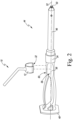
- an alignment guide 10 for use with an implant insertion tool 44 for inserting an acetabular cup component into the acetabulum of a patient during an orthopaedic surgical procedure.
- the alignment guide 10 is configured to be assembled with the implant insertion tool 44, and the radial angle of the alignment guide 10 may be adjusted after assembly as desired by the orthopaedic surgeon or caregiver.
- the alignment guide 10 may be used with a variety of different types of insertion tools, including straight and curved implant insertion tools. Accordingly, the alignment guide 10 may improve ease of use and reduce operation time while being adaptable to surgeon preference. Additionally, in some embodiments, the alignment guide 10 may be constructed from lightweight materials at low cost.
- the illustrative alignment guide 10 has a unitary body formed from a single piece of molded polymer.
- the alignment guide 10 may be formed from a sulfone polymer such as polyphenylsulfone (PPSU).
- PPSU polyphenylsulfone
- the alignment guide 10 may be formed from any resilient polymeric material.
- the alignment guide 10 may be formed from metallic material.
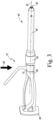
- the alignment guide 10 when the alignment guide 10 is coupled to the implant insertion tool 44, a portion of the implant insertion tool 44 passes through the slot 32 into the interior volume 22, and the interior surface 26 of the arms 18, 20 contacts or engages a corresponding mounting surface of the implant insertion tool 44.
- Each end 28, 30 of the corresponding arms 18, 20 includes a corresponding chamfered edge 34, 36. Because the slot 32 is undersized relative to the body of the insertion tool 44, the arms 18, 20 are urged apart when the chamfered edges 34, 36 engage the body of the implant insertion tool 44, which increases the width of the slot 32 and allows the implant insertion tool 44 to pass into the interior volume 22 as shown in FIGS. 2 and 3 .
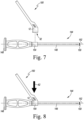
- the riser 14 of the alignment guide 10 extends away from the clip 12 perpendicular to the axis 24 toward a dogleg joint 38.
- the illustrative riser 14 is embodied as a post extending perpendicular from the clip 12, it should be understood that the riser 14 may have another shape and/or extend at another angle away from the axis 24 in other embodiments.
- the riser 14 may be adapted to provide a gripping surface for a surgeon, for example by including mounds, knurling, or other grip-enhancing features.
- the particular indication angle 42 may be selected based upon the desired surgical approach, the desired final inclination angle of the acetabular cup, the alignment of the patient's hip in relation to the operating table, and/or other factors.
- the angle of the patient's hip, the desired final inclination angle of the acetabular cup, and the indication angle 42 may sum to 90 degrees (i.e., vertical in relation to the operating room).
- the patient alignment angle may be 10 degrees
- the desired final inclination angle of the acetabular cup may be 45 degrees
- the indication angle 42 may be 35 degrees such that the indicator 16 is substantially vertical relative to the operating room when the acetabular cup is properly aligned to 45 degrees.
- the patient alignment angle may be five degrees
- the desired final inclination angle of the acetabular cup may be 45 degrees
- the indication angle 42 may be 40 degrees. Of course, other angles may be used.
- the alignment guide 10 may be attached to the implant insertion tool 44 as discussed above.
- the illustrative implant insertion tool 44 has an elongated metallic body 46 having an impact head 48 on its proximal end and an attachment mechanism 50 on its distal end.
- the body 46 defines an imaginary tool axis 52 that extends from the attachment mechanism 50 to the impact head 48.
- the implant insertion tool 44 may have a straight body 46 or, similar to the tool shown in FIGS. 10-12 , in some embodiments the body 46 may be curved, for example to avoid patient anatomy.
- the impact head 48 of the implant insertion tool 44 is illustratively embodied as a metallic strike plate formed in the body 46.
- the strike plate could be embodied as a separate component welded or otherwise secured to the body 46.
- the surgeon holds the assembled implant insertion tool 44 via the body 46 and strikes impact head 48 with a surgical mallet, sledge, or other impaction tool to drive an acetabular cup component 70 into the patient's surgically-prepared acetabular surface 74 (see FIG. 13 ).
- the body 46 includes a mounting surface 54 formed on part of the body 46.
- the illustrative mounting surface 54 is embodied as a conic frustum; however, in other embodiments the mounting surface 54 may be cylindrical or have another shape.
- the body 46 further includes an attachment section 56 adjacent to the mounting surface 54.
- the attachment section 56 is narrower than the mounting surface 54 in at least one dimension.
- the illustrative attachment part 56 includes flat sides 58, 60, which oppose each other to reduce the width of the attachment section 56.
- the chamfered edges 34, 36 engage with the flat sides 58, 60 of the attachment part 56 and force the slot 32 open to allow the attachment section 56 into the interior volume 22.
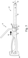
- the surgeon may slide the alignment guide 10 onto the implant insertion tool 44 in the direction 62 until the interior surface 26 contacts the implant insertion tool 44.
- the clip 12 surrounds the tool axis 52.
- the surgeon or other user presses or slides the alignment guide 10 in a direction 66 toward the mounting surface 54.
- the tapered interior surface 26 of the alignment guide 10 engages against the conical frustum mounting surface 54 of the implant insertion tool 44.
- the interior surface 26 is formed so as to contact the mounting surface 54 at three contact points 68 of the interior surface 26.
- the contact points 68 may be formed, for example, via mounds, tabs, ridges, or other features that protrude from the interior surface 26. Of course, in other embodiments, additional contact points 68 may be used.
- the alignment guide 10 When engaged, the alignment guide 10 establishes a friction lock in position on the mounting surface 54. After being locked in position, the alignment guide 10 remains at the rotational angle 64 selected by the surgeon due to frictional forces between the alignment guide 10 and the implant insertion tool 44. The surgeon may unlock the alignment guide 10 by moving the alignment guide 10 in a direction opposite the direction 66, which allows the surgeon to adjust the rotational angle of the alignment guide 10.
- the alignment guide 10 may clip onto the implant insertion tool 44 using any suitable interference fit. For example, illustrative embodiments of alignment guides 10 that attach to the implant insertion tool 44 using an interference fit are shown below in connection with FIGS. 6-12 .
- the illustrative alignment guide 100 for use with an implant insertion tool for inserting an acetabular cup component into the acetabulum of a patient during an orthopaedic surgical procedure.
- the illustrative alignment guide 100 has a unitary body formed from a single piece of molded polymer.
- the alignment guide 100 may be formed from a sulfone polymer such as polyphenylsulfone (PPSU).
- PPSU polyphenylsulfone
- the alignment guide 100 may be formed from any resilient polymeric material.
- the alignment guide 100 may be formed from metallic material.
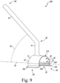
- the alignment guide 100 includes a clip 12, a riser 14, and an elongated indicator 16.
- the clip 12 includes a pair of curved arms 18, 20 that define an interior volume 22, as well as an imaginary axis 24 that extends through the interior volume 22.
- the arms 18, 20 include an interior surface 26 that extends from a distal end 28 of the arm 18 to a distal end 30 of the arm 20.
- the ends 28, 30 define a slot 32 therebetween which the interior volume 22 is accessible.
- the interior surface 26 forms a plano-concave curve that engages a cylindrical mounting surface 154 of an insertion tool 144, as described further below.
- the mounting surface 154 of the implant insertion tool 144 passes through the slot 32 into the interior volume 22, and the interior surface 26 of the arms 18, 20 contacts or engages the mounting surface 154.
- the illustrative arms 18, 20 further include rounded ledges 102, 104 on the respective ends 28, 30.
- the ledges 102, 104 curve away from the slot 32 and may allow for ease of attachment or removal of the alignment guide 100 similar to the chamfered edges 34, 36 of the alignment guide 10.
- the riser 14 of the alignment guide 100 extends away from the clip 12 and the axis 24 toward a dogleg joint 38.
- the illustrative riser 14 includes a grouping of mounds or ridges 108 formed in the surface of the riser 14 to provide a gripping surface for a surgeon.
- the illustrative riser 14 is formed to be hollow. However, it should be understood that in other embodiments the riser 14 may be solid or otherwise shaped.
- the riser 14 may be embodied as a rod extending from the clip 12 to the dogleg joint 38, similar to the riser 14 of the alignment guide 10.
- the alignment guide 100 may be utilized by a surgeon with an implant insertion tool 144 to implant the acetabular cup component 70 into the surgically-prepared acetabulum 84 of a patient (see FIG. 13 ). As shown in FIG. 8 , the alignment guide 100 may be coupled, attached, or otherwise clipped to the implant insertion tool 144 at the mounting surface 154. To do so, the surgeon or other user places the clip 12 of the alignment guide 100 in contact with the mounting surface 154 and then presses the alignment guide 100 in the downwardly direction 62 toward the implant insertion tool 144.
- the surgeon may rotate the alignment guide 100 about the tool axis 152. Because the mounting surface 154 and the interior surface 26 are relatively smooth, the alignment guide 100 may be freely rotated to any angle 64 about the tool axis 52. The surgeon may select the angle based on individual preference, to adjust to patient anatomy, or for other reasons. Additionally or alternatively, in some embodiments the surgeon may remove the alignment guide 100, reposition the alignment guide 100 at the desired angle 64 about the tool axis 52, and then re-attach the alignment guide 100 at the desired angle 64 as discussed above.
- the illustrative alignment guide 200 has a unitary body formed from a single piece of molded polymer.
- the alignment guide 200 may be formed from a sulfone polymer such as polyphenylsulfone (PPSU).
- PPSU polyphenylsulfone
- the alignment guide 200 may be formed from any resilient polymeric material.
- the alignment guide 200 may be formed from metallic material.
- the illustrative alignment guide 200 includes a clip 12, a riser 14, and an elongated indicator 16.
- the clip 12 includes a pair of curved arms 18, 20 that define an interior volume 22, as well as an imaginary axis 24 that extends through the interior volume 22.
- the arms 18, 20 include an interior surface 26 that extends from a distal end 28 of the arm 18 to a distal end 30 of the arm 20.
- the ends 28, 30 define a slot 32 therebetween which the interior volume 22 is accessible.
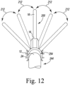
- the interior surface 26 includes a pair of teeth or other projections 202, 204 that project into the interior volume 22. Each tooth 202, 204 is positioned at a respective end 28, 30 of the corresponding arm 18, 20.
- the alignment guide 200 may be attached to an implant insertion tool 244.
- the illustrative implant insertion tool 244 has an elongated metallic body 246 having an impact head 248 on its proximal end and an attachment mechanism 250 on its distal end.
- the body 246 defines an imaginary tool axis 252 that extends from the attachment mechanism 250 to the impact head 248.
- the insertion tool 244 has a curved body 246, which may be used to avoid soft tissue or other patient anatomy.
- the insertion tool 244 may have a straight body 246 similar to the insertion tools of FIGS. 2-5 and 7-8 .
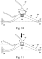
- the body 246 of the insertion tool 244 includes a mounting surface 254 formed on a section of the body 246. As best shown in FIG. 10 , the mounting surface 254 is generally cylindrical. The mounting surface 254 includes multiple ridges or steps 206 running parallel to the tool axis 252. Each pair of ridges 206 is separated by a groove or valley 208.
- the alignment guide 200 may be coupled, attached or otherwise clipped to the implant insertion tool 244 at the mounting surface 254.
- the surgeon or other user places the clip 12 of the alignment guide 200 in contact with the mounting surface 254 and then presses the alignment guide 200 in the downwardly direction 62 toward the implant insertion tool 244.
- the surgeon may slide the alignment guide 200 onto the implant insertion tool 244 in the direction 62 until the interior surface 26 contacts the implant insertion tool 244.
- the teeth 202, 204 engage respective grooves 208 of the mounting surface 254.
- the teeth 202, 204 and a contact point 210 at the top of the interior surface 26 (shown in FIG. 9 ) lock the alignment guide 200 to the insertion tool 244 with an interference fit.
- the axis 24 defined by the alignment guide 200 is parallel to the tool axis 252, as shown in FIG. 11 .
- the surgeon may rotate the alignment guide 200 about the axis 24 after the alignment guide 200 is attached to the insertion tool 244.
- the teeth 202, 204 engage respective ridges 206 and grooves 208 in the mounting surface 254.
- the grooves 208 and ridges 206 cooperate to urge the teeth 202, 204 to come to rest in engagement with respective grooves 208, operating as detents that index rotation of the alignment guide 200.
- the alignment guide 200 may be rotated by the surgeon to any of multiple predetermined angles 212 about the axis 24, based on the arrangement of the ridges 206 and grooves 208 of the mounting surface 254.
- the surgeon may select the angle 212 based on individual preference, to adjust to patient anatomy, or for other reasons.
- the alignment guide 200 remains positively locked to the insertion tool 244 by the teeth 202, 204.
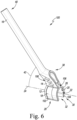
- an acetabular cup component being installed in the acetabulum of a patient's hip using an illustrative alignment guide 10 and implant insertion tool 44 is shown.
- the respective alignment guides 100, 200 and insertion tools 144, 244 may also be used in place of the alignment guide 10 and the insertion tool 44.
- the surgeon secures an acetabular cup component 70 to the insertion tool 44.
- the acetabular cup component 70 may thread onto a threaded tip of the attachment mechanism 50.
- the surgeon uses the implant insertion tool 44 to position the acetabular cup component 70 such that its generally hemispherically-shaped bone-engaging surface 72 is inserted into the patient's surgically-prepared acetabular surface 74 in a desired orientation.
- the surgeon may use the indicator 16 of the alignment guide 10 to measure and adjust the inclination of the acetabular cup component 70.
- the surgeon may adjust the angle of the insertion tool 44 until the indicator 16 is parallel with a vertical reference line 76 (i.e., pointing straight up).
- the vertical reference line 76 may be determined visually by the surgeon in relation to the floor, operating table, or other external reference.
- the surgeon strikes the impact head 48 of the implant insertion tool 44 with a surgical mallet, sledge, or other impaction tool to drive the acetabular cup component 70 into the bone tissue until the acetabular cup component 70 is fully seated in the patient's surgically-prepared acetabular surface 74.
- the surgeon may rotate the implant insertion tool 44 in a direction that loosens (i.e., unthreads) the threads of the tool 44 from a corresponding threaded hole of the acetabular cup component 70.
- the surgeon After releasing the acetabular cup component 70, the surgeon removes the alignment guide 10 from the insertion tool 44.
- the surgeon pulls the alignment guide 10 away from the insertion tool 44 (i.e., opposite the direction 62 of FIG. 3 ), and the insertion tool 44 passes out of the interior volume 22 through the slot 32.
- the surgeon may grasp the riser 14 and pull the alignment guide 10 off the insertion tool 44. Additionally or alternatively, if available, the surgeon may pull on one or more of the rounded ledges 102, 104 to assist in removal of the alignment guide 10.
- the alignment guide 10 may be removed by the surgeon using one hand.
Landscapes
- Health & Medical Sciences (AREA)
- Transplantation (AREA)
- Orthopedic Medicine & Surgery (AREA)
- Heart & Thoracic Surgery (AREA)
- Life Sciences & Earth Sciences (AREA)
- Oral & Maxillofacial Surgery (AREA)
- Engineering & Computer Science (AREA)
- Biomedical Technology (AREA)
- Physical Education & Sports Medicine (AREA)
- Vascular Medicine (AREA)
- Cardiology (AREA)
- Animal Behavior & Ethology (AREA)
- General Health & Medical Sciences (AREA)
- Public Health (AREA)
- Veterinary Medicine (AREA)
- Prostheses (AREA)
- Surgical Instruments (AREA)
Claims (15)
- Eine Neigungsführung [10] zur Verwendung mit einem Implantat-Einsetzungswerkzeug [44] während eines chirurgischen Eingriffs, wobei die Neigungsführung [10] einen Körper beinhaltet, wobei der Körper Folgendes beinhaltet:einen Clip [12], der konfiguriert ist, um mit einer Montagefläche des Implantat-Einsetzungswerkzeugs [44] gekoppelt zu werden, wobei der Clip [12] ein Innenvolumen [22] und eine imaginäre Werkzeugachse [24], die sich durch das Innenvolumen [22] erstreckt, definiert;ein längliches Ansatzelement [14], das sich von dem Clip [12] von der imaginären Werkzeugachse [24] weg zu einer ersten Verbindungsstelle [38] erstreckt; und dadurch gekennzeichnet, dass:der Körper ein einstückiger Körper ist;der einstückige Körper ferner Folgendes beinhaltet:
einen länglichen Indikator [16], der sich von der ersten Verbindungsstelle des länglichen Ansatzelements [14] zu einem distalen Ende [40] erstreckt, wobei der längliche Indikator [16] und die imaginäre Werkzeugachse [24] einen Indikationswinkel [42] definieren, wobei der Indikationswinkel [42] vorbestimmt und fest ist. - Neigungsführung [10] gemäß Anspruch 1, wobei der einstückige Körper einen polymeren Formkörper beinhaltet.
- Neigungsführung [10] gemäß Anspruch 2, wobei der einstückige Körper aus Polyphenylsulfon (PPSU) geformt ist.
- Neigungsführung [10] gemäß Anspruch 1, wobei der einstückige Körper aus einem metallischen Material geformt ist.
- Neigungsführung [10] gemäß Anspruch 1, wobei der Clip [12] einen ersten gebogenen Arm [18], der sich von dem länglichen Ansatzelement [14] weg zu einem ersten Ende [28] erstreckt, und einen zweiten gebogenen Arm [20], der sich von dem länglichen Ansatzelement [14] weg zu einem zweiten Ende [30] erstreckt, beinhaltet, wobei der erste gebogene Arm [18] und der zweite gebogene Arm [20] zusammenwirken, um das Innenvolumen [22] zu definieren, und das erste Ende [28] und das zweite Ende [30] zusammenwirken, um einen Schlitz [32] zu definieren, der Zugang zu dem Innenvolumen [22] bereitstellt.
- Neigungsführung [10] gemäß Anspruch 5, die ferner einen ersten abgerundeten Vorsprung [102] an dem ersten Ende [28] des ersten gebogenen Arms [18] und einen zweiten abgerundeten Vorsprung [104] an dem zweiten Ende [30] des zweiten gebogenen Arms [20] beinhaltet, wobei jeder von dem ersten abgerundeten Vorsprung [102] und dem zweiten abgerundeten Vorsprung [104] von dem Schlitz [32] weg gebogen ist.
- Neigungsführung [10] gemäß Anspruch 5, wobei jedes von dem ersten Ende [28] des ersten gebogenen Arms [18] und dem zweiten Ende [30] des zweiten gebogenen Arms [20] eine abgeschrägte Kante [34, 36] aufweist und wobei die abgeschrägten Kanten [34, 36] konfiguriert sind, um mit dem Implantat-Einsetzungswerkzeug [44] in Eingriff zu kommen und den Schlitz [32] aufzudrücken, wenn sie mit dem Implantat-Einsetzungswerkzeug [44] in Eingriff sind.
- Neigungsführung [10] gemäß Anspruch 5, wobei der erste gebogene Arm [18] und der zweite gebogene Arm [20] eine plankonkave Innenfläche [26] definieren, die konfiguriert ist, um mit einer zylindrischen Montagefläche [54] des Implantat-Einsetzungswerkzeugs [44] in Eingriff zu kommen.
- Neigungsführung [10] gemäß Anspruch 5, wobei der erste gebogene Arm [18] und der zweite gebogene Arm [20] eine konisch zulaufende konkave Innenfläche [26] definieren, die konfiguriert ist, um mit einer kegelstumpfförmigen Montagefläche [54] des Implantat-Einsetzungswerkzeugs [44] in Eingriff zu kommen.
- Neigungsführung [10] gemäß Anspruch 1, wobei der Clip [12] eine Innenfläche [26] beinhaltet, die der Montagefläche [54] des Implantat-Einsetzungswerkzeugs [44] gegenüberliegt, während der Clip [12] mit der Montagefläche [54] gekoppelt ist, wobei die Innenfläche [26] drei Kontaktpunkte umfasst und wobei jeder der drei Kontaktpunkte konfiguriert ist, um mit der Montagefläche [54] des Implantat-Einsetzungswerkzeugs [44] in Eingriff zu kommen.
- Neigungsführung [10] gemäß Anspruch 1, wobei der Clip [12] einen ersten Zahn [202] und einen zweiten Zahn [204] beinhaltet, die sich von einer Innenfläche [26] des Clips [12] hin zu der imaginären Werkzeugachse [24] in das Innenvolumen [22] nach innen erstrecken, und wobei der erste Zahn [202] und der zweite Zahn [204] konfiguriert sind, um mit einer jeweiligen Nut [208] der Montagefläche [54] in Eingriff zu kommen.
- Neigungsführung [10] gemäß Anspruch 11, wobei die Montagefläche [54] eine Vielzahl von Rippen [206] parallel zu der imaginären Werkzeugachse [24] beinhaltet, wobei jedes Paar Rippen [206] durch eine Nut [208] getrennt ist.
- Neigungsführung [10] gemäß Anspruch 11, wobei der Clip [12] einen ersten gebogenen Arm [18], der sich von dem länglichen Ansatzelement [14] weg zu einem ersten Ende [28] erstreckt, und einen zweiten gebogenen Arm [20], der sich von dem länglichen Ansatzelement [14] weg zu einem zweiten Ende [30] erstreckt, beinhaltet, wobei der erste gebogene Arm [18] und der zweite gebogene Arm [20] zusammenwirken, um das Innenvolumen [22] zu definieren, und das erste Ende [28] und das zweite Ende [30] zusammenwirken, um einen Schlitz [32] zu definieren, der Zugang zu dem Innenvolumen [22] bereitstellt, wobei sich der erste Zahn [202] an dem ersten Ende [28] des ersten gebogenen Arms [18] befindet und wobei sich der zweite Zahn [204] an dem zweiten Ende [30] des zweiten gebogenen Arms [20] befindet.
- Ein Set, das mehrere Neigungsführungen [10] gemäß Anspruch 1 umfasst, wobei jede Neigungsführung einen bestimmten Indikationswinkel [42] definiert.
- Set gemäß Anspruch 14, wobei das Set ein Implantat-Einsetzungswerkzeug [44] zum Einsetzen einer Hüftpfannenkomponente in die Hüftgelenkspfanne eines Patienten während eines orthopädischen chirurgischen Eingriffs umfasst und/oder gerade und gebogene Implantat-Einsetzungswerkzeuge [44] umfasst.
Applications Claiming Priority (2)
| Application Number | Priority Date | Filing Date | Title |
|---|---|---|---|
| US16/702,833 US11583417B2 (en) | 2019-12-04 | 2019-12-04 | Removable inclination guide for an implant insertion tool and associated surgical method |
| PCT/EP2020/084686 WO2021110941A1 (en) | 2019-12-04 | 2020-12-04 | Removable inclination guide for an implant insertion tool and associated surgical method |
Publications (3)
| Publication Number | Publication Date |
|---|---|
| EP4069155A1 EP4069155A1 (de) | 2022-10-12 |
| EP4069155B1 true EP4069155B1 (de) | 2025-04-16 |
| EP4069155C0 EP4069155C0 (de) | 2025-04-16 |
Family
ID=73740409
Family Applications (1)
| Application Number | Title | Priority Date | Filing Date |
|---|---|---|---|
| EP20820393.5A Active EP4069155B1 (de) | 2019-12-04 | 2020-12-04 | Entfernbare neigungsführung für ein implantat-einsetzungswerkzeug |
Country Status (6)
| Country | Link |
|---|---|
| US (3) | US11583417B2 (de) |
| EP (1) | EP4069155B1 (de) |
| JP (1) | JP7608462B2 (de) |
| CN (1) | CN114746049B (de) |
| AU (1) | AU2020397230B2 (de) |
| WO (1) | WO2021110941A1 (de) |
Families Citing this family (6)
| Publication number | Priority date | Publication date | Assignee | Title |
|---|---|---|---|---|
| EP3876874A1 (de) * | 2018-11-08 | 2021-09-15 | Neo Medical SA | Wirbelkäfighammer |
| USD1066663S1 (en) * | 2019-12-04 | 2025-03-11 | Depuy Ireland Unlimited Company | Inclination guide |
| US11583417B2 (en) | 2019-12-04 | 2023-02-21 | Depuy Ireland Unlimited Company | Removable inclination guide for an implant insertion tool and associated surgical method |
| KR102752698B1 (ko) * | 2021-09-08 | 2025-01-13 | 주식회사 코렌텍 | 비구 컵 임팩터, 안테버전 가이드 및 그 수술기구 |
| USD1030442S1 (en) * | 2022-04-21 | 2024-06-11 | Depuy Ireland Unlimited Company | Inserter handle |
| USD1120319S1 (en) * | 2022-08-11 | 2026-03-24 | Depuy Ireland Unlimited Company | Inclination guide |
Family Cites Families (45)
| Publication number | Priority date | Publication date | Assignee | Title |
|---|---|---|---|---|
| US3367337A (en) * | 1965-01-15 | 1968-02-06 | Stephen L. Javna | Surgical clamp |
| US5984939A (en) * | 1989-12-05 | 1999-11-16 | Yoon; Inbae | Multifunctional grasping instrument with cutting member and operating channel for use in endoscopic and non-endoscopic procedures |
| US5366458A (en) * | 1990-12-13 | 1994-11-22 | United States Surgical Corporation | Latchless surgical clip |
| US5098437A (en) | 1991-02-13 | 1992-03-24 | Pfizer Hospital Products Group, Inc. | Acetabular cup positioning insert |
| US5284483A (en) * | 1992-09-16 | 1994-02-08 | Zimmer, Inc. | Acetabular cup inserting instrument |
| US5364403A (en) | 1993-09-20 | 1994-11-15 | Zimmer, Inc. | Acetabular cup positioner |
| CH690293A5 (fr) * | 1994-09-06 | 2000-07-14 | Jaquet Orthopedie | Articulation pour composants d'un fixateur externe. |
| US6991656B2 (en) | 2000-04-26 | 2006-01-31 | Dana Mears | Method and apparatus for performing a minimally invasive total hip arthroplasty |
| WO2003041611A2 (en) * | 2001-11-14 | 2003-05-22 | White Michael R | Apparatus and methods for making intraoperative orthopedic measurements |
| DE10200690B4 (de) | 2002-01-10 | 2005-03-03 | Intraplant Ag | Hilfsmittel zur Implantation einer Hüftgelenkendoprothese |
| DE20200990U1 (de) | 2002-01-17 | 2002-03-28 | Aesculap AG & Co. KG, 78532 Tuttlingen | Chirurgische Ziellehre |
| US6887247B1 (en) * | 2002-04-17 | 2005-05-03 | Orthosoft Inc. | CAS drill guide and drill tracking system |
| US7651501B2 (en) | 2004-03-05 | 2010-01-26 | Wright Medical Technology, Inc. | Instrument for use in minimally invasive hip surgery |
| US20030229356A1 (en) * | 2002-06-10 | 2003-12-11 | Donald Dye | Curved acetabular shell impaction instrument and method of use |
| HRP20060188A2 (en) | 2003-11-12 | 2006-09-30 | International Patent Owners (Cayman) Limited | A gauge for use in a surgical procedure |
| US7621926B2 (en) * | 2004-04-16 | 2009-11-24 | Applied Medical Resources Corporation | Multi-fire surgical clip applier |
| US7294133B2 (en) * | 2004-06-03 | 2007-11-13 | Zimmer Technology, Inc. | Method and apparatus for preparing a glenoid surface |
| ATE430523T1 (de) * | 2004-08-20 | 2009-05-15 | Stryker Trauma Sa | Klemmelement und gelenkelement |
| US20100183814A1 (en) * | 2005-08-02 | 2010-07-22 | Victor Rios | Silicone compositions, methods of manufacture, and articles formed therefrom |
| US20070191713A1 (en) * | 2005-10-14 | 2007-08-16 | Eichmann Stephen E | Ultrasonic device for cutting and coagulating |
| US7993348B2 (en) | 2005-12-20 | 2011-08-09 | Howmedica Osteonics Corp. | Curved acetabular positioner, impactor and reamer handle |
| US9339278B2 (en) * | 2006-02-27 | 2016-05-17 | Biomet Manufacturing, Llc | Patient-specific acetabular guides and associated instruments |
| US8608749B2 (en) * | 2006-02-27 | 2013-12-17 | Biomet Manufacturing, Llc | Patient-specific acetabular guides and associated instruments |
| US8603180B2 (en) | 2006-02-27 | 2013-12-10 | Biomet Manufacturing, Llc | Patient-specific acetabular alignment guides |
| US8230863B2 (en) * | 2006-05-30 | 2012-07-31 | Mini-Lap Technologies, Inc. | Platform for fixing surgical instruments during surgery |
| GB0907650D0 (en) * | 2009-05-05 | 2009-07-22 | Depuy Int Ltd | Alignment guide |
| US9358130B2 (en) * | 2012-03-29 | 2016-06-07 | DePuy Synthes Products, Inc. | Surgical instrument and method of positioning an acetabular prosthetic component |
| US9095448B2 (en) * | 2010-05-04 | 2015-08-04 | Depuy International Limited | Method of using an alignment guide |
| EP2605727B1 (de) | 2010-08-16 | 2021-12-15 | Smith & Nephew, Inc. | Auf den patienten abgestimmtes acetabulum-ausrichtwerkzeug |
| US8403939B2 (en) * | 2010-11-05 | 2013-03-26 | Biomet, C.V. | Surgical drill guide |
| US8403869B2 (en) * | 2010-12-30 | 2013-03-26 | Vanderbilt University | Side-deployed medical guidewire torquer |
| US8834480B2 (en) * | 2011-01-17 | 2014-09-16 | Zimmer, Inc. | Adapter for explant system |
| CA2834937A1 (en) | 2011-05-03 | 2012-11-08 | Smith & Nephew, Inc. | Patient-matched guides for orthopedic implants |
| DE102012104390B4 (de) | 2012-05-22 | 2015-10-22 | Aesculap Ag | Implantat – Ausricht-/Zielgerät zum Ausrichtung und/oder Positionieren eines Hüftgelenkpfannen - Implantats während des Implantiervorgangs |
| US9055975B2 (en) * | 2012-09-29 | 2015-06-16 | DePuy Synthes Products, Inc. | Surgical instrument and method of positioning an acetabular prosthetic component |
| US20140137352A1 (en) * | 2012-11-10 | 2014-05-22 | Lydia K Golla | Multipurpose Bendable Tool |
| US9308102B2 (en) | 2013-03-04 | 2016-04-12 | Howmedica Osteonics Corp. | Acetabular cup positioning device |
| US9585768B2 (en) * | 2013-03-15 | 2017-03-07 | DePuy Synthes Products, Inc. | Acetabular cup prosthesis alignment system and method |
| US11026810B2 (en) | 2014-03-07 | 2021-06-08 | Biomet Manufacturing, Llc | Prosthesis alignment system |
| US20160220385A1 (en) | 2015-02-02 | 2016-08-04 | Orthosoft Inc. | Mechanically guided impactor for hip arthroplasty |
| EP3595554A4 (de) * | 2017-03-14 | 2021-01-06 | OrthAlign, Inc. | Hüftersatznavigationssystem und -verfahren |
| US10881530B2 (en) * | 2017-04-28 | 2021-01-05 | Warsaw Orthopedic, Inc. | Surgical instrument and method |
| CN111655187B (zh) | 2018-01-26 | 2024-07-12 | 马科外科公司 | 用于冲击由手术机器人引导的假体的端部执行器、系统和方法 |
| GB201810484D0 (en) * | 2018-06-26 | 2018-08-08 | Smith & Nephew Orthopaedics Ag | Acetabular implant alignment devices and methods |
| US11583417B2 (en) | 2019-12-04 | 2023-02-21 | Depuy Ireland Unlimited Company | Removable inclination guide for an implant insertion tool and associated surgical method |
-
2019
- 2019-12-04 US US16/702,833 patent/US11583417B2/en active Active
-
2020
- 2020-12-04 EP EP20820393.5A patent/EP4069155B1/de active Active
- 2020-12-04 JP JP2022533516A patent/JP7608462B2/ja active Active
- 2020-12-04 CN CN202080083891.5A patent/CN114746049B/zh active Active
- 2020-12-04 WO PCT/EP2020/084686 patent/WO2021110941A1/en not_active Ceased
- 2020-12-04 AU AU2020397230A patent/AU2020397230B2/en active Active
-
2023
- 2023-02-21 US US18/112,208 patent/US12251324B2/en active Active
-
2025
- 2025-03-17 US US19/081,641 patent/US20250205061A1/en active Pending
Also Published As
| Publication number | Publication date |
|---|---|
| US12251324B2 (en) | 2025-03-18 |
| JP2023504702A (ja) | 2023-02-06 |
| EP4069155A1 (de) | 2022-10-12 |
| US11583417B2 (en) | 2023-02-21 |
| JP7608462B2 (ja) | 2025-01-06 |
| CN114746049B (zh) | 2025-07-11 |
| EP4069155C0 (de) | 2025-04-16 |
| CN114746049A (zh) | 2022-07-12 |
| US20250205061A1 (en) | 2025-06-26 |
| WO2021110941A1 (en) | 2021-06-10 |
| US20210169661A1 (en) | 2021-06-10 |
| US20230190493A1 (en) | 2023-06-22 |
| AU2020397230A1 (en) | 2022-07-21 |
| AU2020397230B2 (en) | 2025-09-18 |
Similar Documents
| Publication | Publication Date | Title |
|---|---|---|
| EP4069155B1 (de) | Entfernbare neigungsführung für ein implantat-einsetzungswerkzeug | |
| US12059361B2 (en) | System for preparing a patient's tibia in an orthopaedic joint replacement procedure | |
| AU2022202058B2 (en) | Orthopaedic surgical instrument system for surgically-preparing a patient's femur | |
| JP6433665B2 (ja) | オフセットを設定するための脛骨の整形外科用手術器具 | |
| JP6591142B2 (ja) | オフセット設定のための脛骨トライアル器具 | |
| EP3328291B1 (de) | Hüftkopf- und hüftpfannenimpaktoren zur implantation einer hüftprothese | |
| US12376970B2 (en) | Implant insertion tool for implanting an acetabular component and associated surgical method |
Legal Events
| Date | Code | Title | Description |
|---|---|---|---|
| STAA | Information on the status of an ep patent application or granted ep patent |
Free format text: STATUS: UNKNOWN |
|
| STAA | Information on the status of an ep patent application or granted ep patent |
Free format text: STATUS: THE INTERNATIONAL PUBLICATION HAS BEEN MADE |
|
| PUAI | Public reference made under article 153(3) epc to a published international application that has entered the european phase |
Free format text: ORIGINAL CODE: 0009012 |
|
| STAA | Information on the status of an ep patent application or granted ep patent |
Free format text: STATUS: REQUEST FOR EXAMINATION WAS MADE |
|
| 17P | Request for examination filed |
Effective date: 20220510 |
|
| AK | Designated contracting states |
Kind code of ref document: A1 Designated state(s): AL AT BE BG CH CY CZ DE DK EE ES FI FR GB GR HR HU IE IS IT LI LT LU LV MC MK MT NL NO PL PT RO RS SE SI SK SM TR |
|
| DAV | Request for validation of the european patent (deleted) | ||
| DAX | Request for extension of the european patent (deleted) | ||
| GRAP | Despatch of communication of intention to grant a patent |
Free format text: ORIGINAL CODE: EPIDOSNIGR1 |
|
| STAA | Information on the status of an ep patent application or granted ep patent |
Free format text: STATUS: GRANT OF PATENT IS INTENDED |
|
| INTG | Intention to grant announced |
Effective date: 20241114 |
|
| RIN1 | Information on inventor provided before grant (corrected) |
Inventor name: ANDERSON, JAMES A. Inventor name: PEDDLE, DARRON G. Inventor name: BECK, CLINTON A. |
|
| GRAS | Grant fee paid |
Free format text: ORIGINAL CODE: EPIDOSNIGR3 |
|
| GRAA | (expected) grant |
Free format text: ORIGINAL CODE: 0009210 |
|
| STAA | Information on the status of an ep patent application or granted ep patent |
Free format text: STATUS: THE PATENT HAS BEEN GRANTED |
|
| AK | Designated contracting states |
Kind code of ref document: B1 Designated state(s): AL AT BE BG CH CY CZ DE DK EE ES FI FR GB GR HR HU IE IS IT LI LT LU LV MC MK MT NL NO PL PT RO RS SE SI SK SM TR |
|
| REG | Reference to a national code |
Ref country code: GB Ref legal event code: FG4D |
|
| REG | Reference to a national code |
Ref country code: CH Ref legal event code: EP |
|
| REG | Reference to a national code |
Ref country code: IE Ref legal event code: FG4D |
|
| U01 | Request for unitary effect filed |
Effective date: 20250416 |
|
| U07 | Unitary effect registered |
Designated state(s): AT BE BG DE DK EE FI FR IT LT LU LV MT NL PT RO SE SI Effective date: 20250424 |
|
| PG25 | Lapsed in a contracting state [announced via postgrant information from national office to epo] |
Ref country code: ES Free format text: LAPSE BECAUSE OF FAILURE TO SUBMIT A TRANSLATION OF THE DESCRIPTION OR TO PAY THE FEE WITHIN THE PRESCRIBED TIME-LIMIT Effective date: 20250416 |
|
| PG25 | Lapsed in a contracting state [announced via postgrant information from national office to epo] |
Ref country code: NO Free format text: LAPSE BECAUSE OF FAILURE TO SUBMIT A TRANSLATION OF THE DESCRIPTION OR TO PAY THE FEE WITHIN THE PRESCRIBED TIME-LIMIT Effective date: 20250716 Ref country code: GR Free format text: LAPSE BECAUSE OF FAILURE TO SUBMIT A TRANSLATION OF THE DESCRIPTION OR TO PAY THE FEE WITHIN THE PRESCRIBED TIME-LIMIT Effective date: 20250717 |
|
| PG25 | Lapsed in a contracting state [announced via postgrant information from national office to epo] |
Ref country code: PL Free format text: LAPSE BECAUSE OF FAILURE TO SUBMIT A TRANSLATION OF THE DESCRIPTION OR TO PAY THE FEE WITHIN THE PRESCRIBED TIME-LIMIT Effective date: 20250416 |
|
| PG25 | Lapsed in a contracting state [announced via postgrant information from national office to epo] |
Ref country code: HR Free format text: LAPSE BECAUSE OF FAILURE TO SUBMIT A TRANSLATION OF THE DESCRIPTION OR TO PAY THE FEE WITHIN THE PRESCRIBED TIME-LIMIT Effective date: 20250416 |
|
| PG25 | Lapsed in a contracting state [announced via postgrant information from national office to epo] |
Ref country code: RS Free format text: LAPSE BECAUSE OF FAILURE TO SUBMIT A TRANSLATION OF THE DESCRIPTION OR TO PAY THE FEE WITHIN THE PRESCRIBED TIME-LIMIT Effective date: 20250716 |
|
| PG25 | Lapsed in a contracting state [announced via postgrant information from national office to epo] |
Ref country code: IS Free format text: LAPSE BECAUSE OF FAILURE TO SUBMIT A TRANSLATION OF THE DESCRIPTION OR TO PAY THE FEE WITHIN THE PRESCRIBED TIME-LIMIT Effective date: 20250816 |
|
| U20 | Renewal fee for the european patent with unitary effect paid |
Year of fee payment: 6 Effective date: 20251110 |
|
| PGFP | Annual fee paid to national office [announced via postgrant information from national office to epo] |
Ref country code: GB Payment date: 20251030 Year of fee payment: 6 |
|
| PG25 | Lapsed in a contracting state [announced via postgrant information from national office to epo] |
Ref country code: SM Free format text: LAPSE BECAUSE OF FAILURE TO SUBMIT A TRANSLATION OF THE DESCRIPTION OR TO PAY THE FEE WITHIN THE PRESCRIBED TIME-LIMIT Effective date: 20250416 |
|
| PG25 | Lapsed in a contracting state [announced via postgrant information from national office to epo] |
Ref country code: CZ Free format text: LAPSE BECAUSE OF FAILURE TO SUBMIT A TRANSLATION OF THE DESCRIPTION OR TO PAY THE FEE WITHIN THE PRESCRIBED TIME-LIMIT Effective date: 20250416 |
|
| PG25 | Lapsed in a contracting state [announced via postgrant information from national office to epo] |
Ref country code: SK Free format text: LAPSE BECAUSE OF FAILURE TO SUBMIT A TRANSLATION OF THE DESCRIPTION OR TO PAY THE FEE WITHIN THE PRESCRIBED TIME-LIMIT Effective date: 20250416 |
|
| PLBE | No opposition filed within time limit |
Free format text: ORIGINAL CODE: 0009261 |
|
| STAA | Information on the status of an ep patent application or granted ep patent |
Free format text: STATUS: NO OPPOSITION FILED WITHIN TIME LIMIT |
|
| REG | Reference to a national code |
Ref country code: CH Ref legal event code: L10 Free format text: ST27 STATUS EVENT CODE: U-0-0-L10-L00 (AS PROVIDED BY THE NATIONAL OFFICE) Effective date: 20260225 |
|
| 26N | No opposition filed |
Effective date: 20260119 |