EP4069467B1 - Appareil à agrafes et procédés d'agrafage - Google Patents
Appareil à agrafes et procédés d'agrafage Download PDFInfo
- Publication number
- EP4069467B1 EP4069467B1 EP20811139.3A EP20811139A EP4069467B1 EP 4069467 B1 EP4069467 B1 EP 4069467B1 EP 20811139 A EP20811139 A EP 20811139A EP 4069467 B1 EP4069467 B1 EP 4069467B1
- Authority
- EP
- European Patent Office
- Prior art keywords
- indexing
- staple
- rung
- tab
- head
- Prior art date
- Legal status (The legal status is an assumption and is not a legal conclusion. Google has not performed a legal analysis and makes no representation as to the accuracy of the status listed.)
- Active
Links
Images








Classifications
-
- B—PERFORMING OPERATIONS; TRANSPORTING
- B25—HAND TOOLS; PORTABLE POWER-DRIVEN TOOLS; MANIPULATORS
- B25C—HAND-HELD NAILING OR STAPLING TOOLS; MANUALLY OPERATED PORTABLE STAPLING TOOLS
- B25C5/00—Manually operated portable stapling tools; Hand-held power-operated stapling tools; Staple feeding devices therefor
-
- B—PERFORMING OPERATIONS; TRANSPORTING
- B25—HAND TOOLS; PORTABLE POWER-DRIVEN TOOLS; MANIPULATORS
- B25C—HAND-HELD NAILING OR STAPLING TOOLS; MANUALLY OPERATED PORTABLE STAPLING TOOLS
- B25C5/00—Manually operated portable stapling tools; Hand-held power-operated stapling tools; Staple feeding devices therefor
- B25C5/16—Staple-feeding devices, e.g. with feeding means, supports for staples or accessories concerning feeding devices
- B25C5/1606—Feeding means
- B25C5/1624—Feeding means employing mechanical feeding means
- B25C5/1627—Feeding means employing mechanical feeding means of incremental type
-
- B—PERFORMING OPERATIONS; TRANSPORTING
- B65—CONVEYING; PACKING; STORING; HANDLING THIN OR FILAMENTARY MATERIAL
- B65C—LABELLING OR TAGGING MACHINES, APPARATUS, OR PROCESSES
- B65C7/00—Affixing tags
- B65C7/003—Affixing tags using paddle-shaped plastic pins
-
- B—PERFORMING OPERATIONS; TRANSPORTING
- B65—CONVEYING; PACKING; STORING; HANDLING THIN OR FILAMENTARY MATERIAL
- B65C—LABELLING OR TAGGING MACHINES, APPARATUS, OR PROCESSES
- B65C7/00—Affixing tags
- B65C7/003—Affixing tags using paddle-shaped plastic pins
- B65C7/005—Portable tools
- B65C7/006—Portable tools electrically actuated
-
- G—PHYSICS
- G09—EDUCATION; CRYPTOGRAPHY; DISPLAY; ADVERTISING; SEALS
- G09F—DISPLAYING; ADVERTISING; SIGNS; LABELS OR NAME-PLATES; SEALS
- G09F3/00—Labels, tag tickets, or similar identification or indication means; Seals; Postage or like stamps
- G09F3/08—Fastening or securing by means not forming part of the material of the label itself
- G09F3/12—Fastening or securing by means not forming part of the material of the label itself by pins, staples, or the like
-
- B—PERFORMING OPERATIONS; TRANSPORTING
- B25—HAND TOOLS; PORTABLE POWER-DRIVEN TOOLS; MANIPULATORS
- B25C—HAND-HELD NAILING OR STAPLING TOOLS; MANUALLY OPERATED PORTABLE STAPLING TOOLS
- B25C5/00—Manually operated portable stapling tools; Hand-held power-operated stapling tools; Staple feeding devices therefor
- B25C5/02—Manually operated portable stapling tools; Hand-held power-operated stapling tools; Staple feeding devices therefor with provision for bending the ends of the staples on to the work
- B25C5/0221—Stapling tools of the table model type, i.e. tools supported by a table or the work during operation
- B25C5/0228—Stapling tools of the table model type, i.e. tools supported by a table or the work during operation power-operated
Definitions
- the present disclosure relates generally to staple apparatus and methods for stapling and, more particularly, to stapling apparatus configured to linearly feed a staple chain and methods of linearly feeding a staple chain with a staple apparatus. More specifically, the invention relates to a staple apparatus according to the preamble of claim 1, an indexing apparatus according to the preamble of claim 9 and a method according to claim 10.
- Staple apparatus are known to utilize a rotating wheel to engage a staple chain and a feed pawl and ratchet system to advance the staple chain in the staple apparatus. Such systems may sometimes experience failure of the feed mechanism when feeding a staple chain with the staple apparatus. Accordingly, improvements may be made over existing systems to reduce the occurrence of such failures.
- the invention provides a staple apparatus according to claim 1, an indexing apparatus according to claim 9 and a method according to claim 10.
- the staple apparatus comprises a staple head movable in a first staple direction from a head retracted position to a head extended position.
- the staple apparatus further comprises an indexing apparatus comprising an index biasing member and an indexing member.
- the indexing member is positioned at least partially within an indexing area and biased with the index biasing member toward a member extended position relative to the indexing area.
- the indexing member is movable in a first indexing direction from the member extended position to a member retracted position relative to the indexing area.
- the first indexing direction comprises a directional component comprising the first staple direction.
- the indexing member defines a rung travel path and further comprises an indexing tab comprising a ramp surface positioned to taper the rung travel path in the first indexing direction.
- the indexing tab further comprises a shoulder positioned past at least a portion of the ramp surface in the first indexing direction.
- the indexing apparatus for indexing a staple chain comprises a support member, an index biasing member, and an indexing member positioned at least partially within an indexing area and biased with the index biasing member toward a member extended position relative to the indexing area.
- the indexing member is movable in a first indexing direction from the member extended position to a member retracted position relative to the indexing area.
- the indexing member defines a rung travel path and further comprises an indexing tab comprising a ramp surface positioned to taper the rung travel path in the first indexing direction.
- the indexing tab further comprises a shoulder positioned past at least a portion of the ramp surface in the first indexing direction.
- a staple chain positioning apparatus can comprise a push member movable in an extension direction and a slide member configured to slide in a slide direction transverse to the extension direction.
- An interface between the slide member and the push member can cause movement of the push member in the extension direction in response to movement of the slide member in the slide direction.
- the interface can comprise an interface protrusion positioned within the interface slot.
- FIG. 1 illustrates a staple apparatus 101 incorporating features of the disclosure.
- a staple chain 103 can be wound on a storage spool 105 that is rotatably mounted to the staple apparatus 101.
- An end 107 of the staple chain 103 can be fed into a slot 109 of the staple apparatus 101 and interfaced with the apparatus, as discussed below, to fasten articles together with a staple separated from the staple chain.
- the articles to be attached together can be inserted into a reception area 115 of the staple apparatus 101 and then the staple apparatus 101 may separate a staple from the staple chain 103 to fasten the articles together.
- FIG. 28 illustrates a staple apparatus 101 incorporating features of the disclosure.
- a staple chain 103 can be wound on a storage spool 105 that is rotatably mounted to the staple apparatus 101.
- An end 107 of the staple chain 103 can be fed into a slot 109 of the staple apparatus 101 and interfaced with the apparatus, as discussed below, to fasten articles together with a staple separated from the staple chain.
- a staple 2801 separated from the staple chain 103 can comprise a rung 2805 extending between a first rail segment 2803a and a second rail segment 2803b.
- a first article 2901 may be fastened to a second article 2903 by the staple 2801 wherein the rung 2805 extends through openings in the articles 2901, 2903 while the rail segments 2803a, 2803b anchor the ends of the rung 2805 to prevent inadvertent unfastening of the articles 2901, 2903 from one another.
- the staple apparatus 101 can include a closure 111 pivotally mounted to a housing 113.
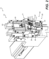
- An interior area defined by the closure 111 and the housing 113 can contain an assembly 201 of the staple apparatus 101 illustrated in FIG. 2 .
- features of a front 203 of the assembly 201 can be exposed by pivoting the closure 111 from the closed position (shown in FIG. 1 ) to an open position (not shown).
- the staple apparatus 101 can be considered the entire apparatus shown in FIG. 1 or any component or combination of components of the assembly 201 illustrated in FIGS. 2-19 and 22-23 .
- the staple chain is considered part of the staple apparatus. In further embodiments, the staple chain is not considered part of the staple apparatus.
- FIGS. 2-3 and 6-7 illustrate a staple head 205 that may optionally be considered as part of the staple apparatus.
- the staple apparatus 101 is considered as including the staple head 205 although the staple head 205 may not be considered as part of the staple apparatus 101 in further embodiments.
- the staple head 205 may be positioned in a head retracted position. Referring to FIGS. 6-7 , the staple head 205 may be moved in the first staple direction 601 from the head retracted position shown in FIG. 6 to the head extended position shown in FIG. 7 .
- the staple head 205 can also be moved in a second staple direction 701, opposite the first staple direction 601, from the head extended position shown in FIG.
- the staple head 205 is considered all portions of the assembly 201 that move together as a single unit from the head retracted position (shown in FIG. 6 ) to the head extended position (shown in FIG.
- the staple head 205 does not include the support member 409, if provided, of the indexing apparatus 207 discussed below.
- the staple apparatus 101 can comprise an indexing apparatus 207.
- the indexing apparatus 207 can comprise one or more of the lower row of bracketed exploded components shown in FIGS. 3-5 .
- the indexing apparatus 207 can comprise an indexing member that may comprise a one-piece member in some embodiments.
- the indexing member 403 can optionally comprise one or a combination of the components bracketed in FIG. 4 .
- the indexing member 403 may be at least partially positioned within an indexing area 401.
- the indexing area 401 may comprise a recess within a support member 409 of the indexing apparatus 207.
- the support member 409 may be fixed for movement with the staple head 205.
- apertures 411 of the support member 409 may receive fasteners, such as the bolts 209 illustrated in FIG. 2 , to fixedly fasten the support member 409 to the staple head 205.
- the staple head 205 and support member 409 may move together as a single unit in the first staple direction 601 and the second staple direction 701 of the staple head 205.
- the indexing area may be defined at least partially or entirely by the staple head 205. As such, the indexing area 401 may travel together with the staple head 205 (e.g., as part of the staple head 205 and/or as part of the indexing apparatus 207).
- the indexing apparatus 207 may include a cover member 413.
- the cover member 413 may be fastened to the support member 409, wherein the cover member 413 can at least partially define the indexing area 401.
- the indexing area 401 may be defined between the support member 409 and the cover member 413.
- the indexing member 403 can be movable in a first indexing direction 703 from the member extended position (see FIG. 7 ) to a member retracted position (see FIG. 6 ) relative to the indexing area 401.
- the indexing member 403 can also be movable in a second indexing direction 705 from the member retracted position (see FIG. 6 ) to the member extended position (see FIG. 7 ).
- the first indexing direction 703 can comprise a directional component comprising the first staple direction 601 of the staple head 205.
- the travel path 1001 of the indexing member 403 in the first indexing direction 703 can extend at an angle relative to the travel path 1003 of the staple head 205 in the first staple direction 601.
- the resultant of the first indexing direction 703 may be substantially identical to the resultant of the first staple direction 601.
- the travel path 1001 of the indexing member 403 in the first indexing direction 703 can be parallel to the travel path 1003 of the staple head 205 in the first staple direction 601.
- the indexing member 403 may be biased with an index biasing member 415 toward the member extended position (see FIG. 7 ) relative to the indexing area 401.
- a force 602 may be applied to the indexing member 403 to cause the indexing member 403 to travel in the first indexing direction 703, against the force applied by the index biasing member 415, to the member retracted position shown in FIG. 6 .
- the index biasing member 415 can bias the indexing member 403 to travel within the indexing area 401 back along the second indexing direction 705 from the member retracted position (see FIG. 6 ) to the member extended position (see FIG. 7 ).
- the index biasing member 415 can comprise the illustrated extension spring.
- the index biasing member 415 can comprise another type of spring such as a leaf spring, compression spring, or a length of resilient material.
- the indexing member 403 can define a rung travel path 1005.
- the rung travel path 1005 can be defined between the indexing member 403 and an inner surface 1007 of the cover member 413.
- the indexing member 403 can further comprise an indexing tab.
- a single indexing tab may be provided although a plurality of indexing tabs may be provided in further embodiments.
- the plurality of indexing tabs 405a-d and 407a-d can be provided although the plurality of indexing tabs may comprise a single pair of indexing tabs or three or more indexing tabs in further embodiments.
- the plurality of indexing tabs may comprise one or more rows of indexing tabs.
- the plurality of indexing tabs can comprise the illustrated first row 1603a of four indexing tabs 405a-d although greater than or less than four indexing tabs may be provided in the first row in further embodiments.
- each indexing tab of the plurality of indexing tabs 405a-d of the first row 1603a of indexing tabs can be identical to the other indexing tabs of the plurality of indexing tabs although different indexing tab configurations may be provided in further embodiments.
- the plurality of indexing tabs can comprise the illustrated second row 1603b of four indexing tabs 407a-d although greater than or less than four indexing tabs may be provided in the second row in further embodiments.
- each indexing tab of the plurality of indexing tabs 407a-d of the second row 1603b of indexing tabs can be identical to the other indexing tabs of the plurality of indexing tabs although different indexing tab configurations may be provided in further embodiments.
- each row 1603a, 1603b can extend transverse to the first indexing direction 703. In some embodiments, each row 1603a, 1603b can extend in a direction that is substantially perpendicular to the first indexing direction 703.
- the plurality of indexing tabs can comprise a plurality of two or more indexing tabs arranged in a column of indexing tabs that extend in the first indexing direction.
- a first column 1601a of indexing tabs can be provided that extends in the first indexing direction 703.
- the first column 1601a of indexing tabs can comprise a corresponding first pair 405a, 407a of indexing tabs although the first column 1601a of indexing tabs may comprise three or more indexing tabs in further embodiments.
- the plurality of indexing tabs may comprise a second column 1601b of indexing tabs that extends in the first indexing direction 703.
- the second column 1601b of indexing tabs can comprise another corresponding first pair 405b, 407b of indexing tabs although the second column 1601b of indexing tabs may comprise three or more indexing tabs in further embodiments.
- the plurality of indexing tabs may comprise a third column 1601c of indexing tabs that extends in the first indexing direction 703.
- the third column 1601c of indexing tabs can comprise another corresponding first pair 405c, 407c of indexing tabs although the third column 1601c of indexing tabs may comprise three or more indexing tabs in further embodiments.
- the plurality of indexing tabs may comprise a fourth column 1601d of indexing tabs that extends in the first indexing direction 703.
- the fourth column 1601d of indexing tabs can comprise another corresponding first pair 405d, 407d of indexing tabs although the fourth column 1601d of indexing tabs may comprise three or more indexing tabs in further embodiments. Although four columns of indexing tabs are illustrated, more or less columns of indexing tabs may be provided in further embodiments.
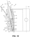
- FIG. 10 is a cross-sectional view along line 10-10 of FIG. 8 , in the first indexing direction 703 and in a plane perpendicular to a rotation axis 1009 discussed below.
- the cross-sectional view illustrates the cross section of the corresponding first pair 405b, 407b of the second column 1601b of indexing tabs.
- each indexing tab can comprise a ramp surface 1011 positioned to taper the rung travel path 1005 in the first indexing direction 703 and a shoulder 1013 positioned past at least a portion of the ramp surface 1011 in the first indexing direction 703.
- FIG. 8 illustrates the indexing apparatus 207 with the cover member 413 while FIG. 9 illustrates the indexing apparatus 207 without the cover member 413 for clarity.
- the cover member 413 can include a staple chain slot 801 passing through the cover member 413 into the indexing area 401.
- the staple chain slot 801 is wide enough to receive the width of the staple chain defined between outer edges of opposed rails 803a, 803b.
- the rungs 805 of the staple chain 103 can be equally spaced apart in series along the length of the staple chain 103. Each rung 805 includes a first end attached to a first rail 803a of the opposed rails and a second end attached to a second rail 803b of the opposed rails.
- the staple chain 103 may be fed along direction 1015 into the staple chain slot 801 and then fed in the first indexing direction 703 through the rung travel path 1005.
- a rung 805 encountering the ramp surface 1011 of the indexing tab can slide over and past the ramp surface 1011 and then be received within the shoulder 1013.
- the shoulder 1013 can then act as a stop to inhibit movement of the rung 805 back over the shoulder to the ramp surface 1011.
- moving the staple head 205 in the first staple direction 601 while extending indexing member 403 in the second indexing direction 705 toward the member extended position can feed the staple chain 103 through the staple chain slot 801. As shown in FIGS.
- the cover member may further comprise a rung tab 807.
- the rung tab 807 can comprise a ramp 1017 to permit passage of a rung 805 of the staple chain 103 over the rung tab 807 when feeding a portion of the staple chain 103 into the staple chain slot 801.
- the rung tab 807 can further comprise a shoulder 1019 to inhibit passage of the rung 805 of the staple chain 103 back over the rung tab 807 to inhibit a movement the portion of the staple chain 103 out of the staple chain slot 801.
- indexing member 403 can interface with portions of the staple chain 103 to provide stable and reliable feeding of the staple chain 103 with the staple apparatus 101.
- the outer edge(s) 901a of one or more outer indexing tabs such as the outer edges 901a of the indexing tabs 405a, 407a of the first column 1601a of indexing tabs can abut or extend closely to the inner edge 903a of the first rail 803a of the staple chain 103.
- FIG. 9 the outer edge(s) 901a of one or more outer indexing tabs such as the outer edges 901a of the indexing tabs 405a, 407a of the first column 1601a of indexing tabs can abut or extend closely to the inner edge 903a of the first rail 803a of the staple chain 103.
- the outer edge(s) 901b of one or more outer indexing tabs such as the outer edges 901b of the indexing tabs 405d, 407d of the fourth column 1601d of indexing tabs can abut or extend closely to the inner edge 903b of the second rail 803b of the staple chain 103. Consequently, the staple chain 103 can be reliably trapped by the outer surfaces of the outer indexing tabs to provide proper lateral alignment of the staple chain 103 being fed into the staple apparatus 101.
- providing a column of two indexing tabs can provide simultaneous gripping of two adjacent rungs 805 to further enhance the stability of the connection between the indexing member 403 and the staple chain 103 to avoid inadvertent disengagement of the staple chain 103 from the indexing member 403 while feeding the staple chain through the rung travel path 1005 with the indexing member 403. Still further, providing multiple columns 1601a-d and rows 1603a-b of indexing tabs can help prevent tilting of the staple chain 103 within the rung travel path 1005 as well as support the rung 805 that may enhance stability, particularly if the rung is flexible and may deform or flex if not otherwise supported at multiple locations along the width of the rung.
- features of the cover member 413 can interface with portions of the staple chain 103 to further enhance stable and reliable feeding of the staple chain 103 with the staple apparatus 101.
- FIG. 12 shows a rear view of the cover member 413 of FIG. 8 with the staple chain 103 with the remaining portions of the indexing member 403 removed for discussion purposes.
- a recess 1201 may be defined in the inner surface 1007 of the cover member 413 that can cooperate with the recess of the support member 409 to define the indexing area 401.
- the inner surface 1007 can comprise a plurality of grooves such as a first pair of grooves 1203a, 1203b. As can be appreciated by FIG.
- the grooves 1203a, 1203b are formed in the inner surface 1007, it will be appreciated that the grooves extend in the first indexing direction 703 and face the indexing area 401.
- the grooves 1203a, 1203b correspondingly receive protruding portions of the rails 803a, 803b.
- Providing the grooves 1203a, 1203b that receive the corresponding rails 803a, 803b can help align the rails and maintain the rails along a predetermined path, thereby reducing errors in feeding the staple chain 103 with the staple apparatus 101.
- the rung tab 807 can comprise a plurality of rung tabs 807 arranged in a row 1401 (see FIG. 14 ) extending in a direction transverse (e.g., perpendicular) to the first indexing direction 703.
- the plurality of rung tabs 807 can comprise three rung tabs.
- the rails 803a, 803b of the wider staple chain 103 may pass through slots defined between the outer opposed sides of the staple chain slot 801 and the outer two rung tabs 807 as shown in FIG. 14 .
- the rails 803a, 803b of the narrower staple chain 103 may pass through slots defined between the outer two rung tabs 807 and the middle rung tab 807 as shown in FIG. 15 .
- the plurality of grooves of the inner surface 1007 comprise a second pair of grooves 1205a, 1205b that extend in the first indexing direction 703 and face the indexing area 401.
- the second pair of grooves 1205a, 1205b can correspondingly receive protruding portions of the rails 803a, 803b of the narrower rail shown in FIG. 15 to help align and maintain the rails along a predetermined path.
- the indexing apparatus 207 can be designed to selectively release the staple chain 103 from the staple apparatus 101, for example, to change the width of the staple chain. Once the staple chain 103 is released, the storage spool 105 (see FIG. 1 ) may be removed and another storage spool with the desired width may be loaded to the staple apparatus 101.
- the indexing tab(s) 405b, 407b may be movable relative to a body 1021 from an engagement position (see FIG. 10 ) where the ramp surface 1011 tapers the rung travel path 1005 to a disengagement position (see FIG. 11 ) wherein the taper of the rung travel path 1005 is reduced, such as eliminated.
- the rungs 805 may be passed over the indexing tabs 405b, 407b as the staple chain 103 is pulled out of the staple chain slot 801.
- the body 1021 may be integral with the indexing tab(s) 405b, 407b wherein the mixing tabs may comprise a flexible portion that can be flexed relative to the body 1021 to move the indexing tab(s) 405b, 407b relative to the body 1021 to achieve the disengagement position shown in FIG. 11 .
- the indexing tab(s) may comprise a pivot member 417 that is movable relative to the body 1021 such that a portion (e.g., the ramp surface) of the indexing tab extends through an opening 419 (see FIG. 4 ) in the body 1021.
- the body 1021 may optionally comprise four openings 419, wherein each opening can accommodate one or a column of ramp surfaces of the indexing tabs.
- the pivot member 417 may comprise a pivot pin 501 comprising pivot protrusions that may fit within pivot cavities 503 to allow the pivot member 417 to be rotatably mounted relative to the body 1021 of the indexing member 403 about the rotation axis 1009 (see FIG.
- the indexing member 403 can further comprise a tab biasing member to bias the indexing tab(s) toward the engagement position shown in FIG. 10 .
- the tab biasing member can comprise a torsion spring 421.
- the indexing member 403 may comprise features that allow selection between a single rung staple 2001 (see FIG. 20 ) or a double rung staple 2101 (see FIG. 21 ).
- the single rung staple 2001 can comprise a single rung 2805 connected between rail segments 2803a, 2803b.
- the double rung staple 2101 of FIG. 21 can comprise a pair of rungs 2805 connected between rail segments 2803a, 2803b. Selection between the single rung staple 2001 and the double rung staple 2101 will be described with initial reference to the indexing apparatus 207 shown in FIGS. 16-19 wherein the indexing member 403 is illustrated without the cover member 413 for description purposes.
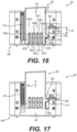
- the indexing apparatus 207 can comprise a stop device 1600.
- the stop device 1600 can comprise a shoulder 1602 configured to move relative to the indexing member 403 to engage a portion 1701 (see FIG. 17 ) of the indexing member 403 to reduce a length of a stroke of the indexing member between the member extended position and the member retracted position.
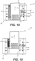
- the length of the stroke S1 shown in FIG. 16 is less than the length of the stroke S2 shown in FIG. 18 since the shoulder 1602 is moved relative to the indexing member to engage the portion 1701 of the indexing member 403 to obstruct full movement of the indexing member 403 relative to the support member 409.
- the length of the stroke S2 shown in FIG. 18 can be increased to be greater than the length of the stroke S1 shown in FIG. 16 by moving the shoulder 1602 relative to the indexing member 403 to prevent engagement with the portion 1701 of the indexing member 403 to allow full movement of the indexing member 403 relative to the support member 409.
- the portion 1701 of the indexing member 403 may comprise the illustrated protrusion 1701 extending within a stroke path 1605 defined by the support member 409.
- the stroke path 1605 can comprise a groove formed within the support member 409 that can receive the protrusion 1701 and permit travel of the protrusion within the groove throughout the stroke path 1605 along the stroke length described above.
- the stop device 1600 can comprise a protrusion that comprises the shoulder 1602. The protrusion of the stop device 1600 is considered the portion of the stop device 1600 that extends into the stroke path 1605 in the single rung staple position shown in FIGS. 16-17 . As shown in FIGS.
- the protrusion comprising the shoulder 1602 of the stop device 1600 can be moved into the stroke path 1605 to reduce an effective length of stroke path that reduces the length of the stroke S1 of the indexing member 403.
- the shoulder 1602 of the stop device 1600 can be moved relative to the indexing member 403 to engage the portion (e.g., protrusion 1701) of the indexing member to reduce the extent that the indexing member 403 extends relative to the support member 409 to the member extended position (see FIG. 17 ).
- the portion e.g., protrusion 1701
- the protrusion comprising the shoulder 1602 of the stop device 1600 can be moved out of the stroke path 1605 to increase an effective length of stroke path that increases the length of the stroke S2 of the indexing member 403.
- the shoulder 1602 of the stop device 1600 can be moved relative to the indexing member 403 to be free from engaging the portion (e.g., protrusion 1701) of the indexing member to increase the extent that the indexing member 403 extends relative to the support member 409 to the member extended position (see FIG. 19 ).
- FIGS. 24-29 illustrate various alternative staples 2401, 2601, 2801 of the single rung staple 2001 discussed above.
- FIGS. 28-29 illustrate the rung 2805 of the staple 2801 positioned at the approximate midpoint of the rail segments 2803a, 2803b.
- positioning the rung 2805 at the approximate midpoint of the rail segments can provide a strong staple 2801 to help inhibit pulling out of the rail segments once fastened as shown in FIG. 29 .
- embodiments including the single rung 2805 may be positioned along the first rail segment 2403a, 2603a and the second rail segment 2403b, 2603b at a location offset from the midpoint of the rail segments.
- providing a staple with a rung that is offset from the midpoint of the rail segments can reduce the force necessary to pull out the rail segments once fastened as shown in FIGS. 25-27 . Reducing the force for separation may be desired to reduce the effort necessary to separate the articles.
- the staple apparatus 101 may comprise a staple chain positioning apparatus 211. Exploded front and rear perspective views of embodiments of the staple chain positioning apparatus 211 are respectively shown in the bracketed top row of components in FIGS. 4-5 .
- the staple chain positioning apparatus 211 can comprise a push member 213.
- the push member 213 can include a tongue 505 that can be slidably received within a channel 507 of a cover member 509.
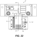
- the channel 507 can provide a linear guide path from the tongue 505 to facilitate a linear movement of the push member 213 along extension direction 2201 or retraction direction 2202 (See FIG. 22 ).
- the extension direction 2201 can comprise a directional component of the first indexing direction 703 of the indexing member 403.
- FIGS. 22-23 illustrate the indexing apparatus 207 without the cover member 413 of the indexing apparatus for discussion purposes.
- the push member 213 can further include an abutment surface 2301 that can abut an abutment surface 2303 of the indexing member 403 to adjust the extent that the indexing member 403 retracts relative to the indexing area 401 when the staple head 205 is in the head retracted position shown in FIG. 6 .
- the staple chain positioning apparatus 211 can further comprise a slide member 423 configured to slide in a slide direction 425 transverse (e.g., substantially perpendicular) to the extension direction 2201 of the push member 213.
- an interface between the slide member 423 and the push member 213 can cause movement of the push member in the extension direction 2201 in response to movement of the slide member in the slide direction 425.
- the interface can comprise a protrusion positioned within an interface slot.
- the slide member 423 may comprise a protrusion positioned within an interface slot of the push member 213.
- the slide member 423 can comprise an interface slot 427 and the push member 213 can comprise a protrusion 511 (see FIG. 5 ).
- the protrusion 511 of the push member 213 can be positioned within the interface slot 427 of the slide member 423.
- the interface slot 427 can extend along a slot path direction 429.
- the slot path direction 429 can comprise a first directional component comprising the slide direction 425 and a second directional component comprising the extension direction 2201 of the push member 213. Consequently, due to the interface of interface slot 427 of the slide member 423 and the protrusion 511 of the push member 213, movement of the slide member 423 in the slide direction 425 will cause movement of the protrusion 511 as well as the abutment surface 2301 in the retraction direction 2202.
- the cover member 509 of the staple chain positioning apparatus 211 can comprise a cover slot 433 extending in the slide direction 425.
- a positioning protrusion 431 of the slide member 423 can be positioned to extend through the cover slot 433 to allow a user to contact the positioning protrusion 431 to move the slide member 423 and consequently the push member 213 in response to the movement of the slide member 423.
- the method can comprise moving the staple head 205 in the first staple direction 601 from the head retracted position while the index biasing member 415 biases the indexing member 403 to move relative to the staple head 205 in a second indexing direction 705 opposite the first indexing direction 703 from the member retracted position shown in FIGS. 6 , 16 and 18 to the member extended position shown in FIGS. 7 , 17 and 19 . While the indexing member 403 moves in the second indexing direction 705 from the member retracted position to the member extended position, a portion of the staple chain 103 passes over the ramp 1017 of the rung tab 807 and is then fed into the staple chain slot 801.
- the indexing member 403 is in the member extended position as shown in FIGS. 7 , 17 and 19 .
- the staple head 205 can then continue to move together with the indexing member 403 in the first staple direction 601 while the indexing member 403 is in the member extended position until the staple head achieves the head extended position shown in FIG. 7 .
- a first rung 805a (see FIG. 10 ) of the staple chain 103 can be engaged with the shoulder 1013 of the index tab 407b.
- the shoulder 1013 of the index tab 407b engages the first rung 805a while the first rung 805a and index tab 407b are moved together with the staple head 205 in the first staple direction 601 toward the head extended position shown in FIG. 7 .
- methods may include adjusting a length of a stroke of the indexing member to change the number of rungs 805 of the staple chain 103 that pass over the ramp surface 1011 of the indexing tab when moving the staple head 205 in the second staple direction 701 opposite the first staple direction from the head extended position (see FIG. 7 ) to the head retracted position (see FIG. 6 ).
- to the stop device may include a protrusion 215 that can extend through a slot 217 in the cover member 413.
- a user may push the protrusion 215 in a direction toward the staple chain slot 801. Once moved, as shown in FIGS.
- the protrusion of the stop device 1600 comprising the shoulder 1602 is moved into the stroke path 1605 so that the shoulder 1602 interferes with the protrusion 1701 of the indexing member 403 in the extended position (see FIG. 17 ), thereby reducing the length of the stroke S1 of the indexing member 403 to index by one rung as discussed below.
- a user may push the protrusion 215 in a direction away from the staple chain slot 801. Once moved, as shown in FIGS.
- the protrusion of the stop device 1600 comprising the shoulder 1602 is moved out of the stroke path 1605 and therefore does not interfere with the protrusion 1701 of the indexing member 403 in the extended position (see FIG. 19 ), thereby increasing the length of the stroke S2 of the indexing member 403 to index by two rungs as discussed below.
- the fastener head can then begin to move from the head extended position shown in FIG. 7 back toward the head retracted position shown in FIG. 6 in order to increment one or two rungs up the staple chain 103 depending on whether the stop device 1600 is positioned for single or double rung staple production as discussed above.
- the staple head 205 begins to move in the second staple direction 701
- the staple head 205 and the indexing member 403 biassed in the member extended position shown in FIG. 7 by the index biasing member 415) move together with the staple chain 103.
- the staple head 205, indexing member 403 (based in the extended position shown in FIG.
- the second rung 805b passes over the ramp surface 1011 of the indexing tab 407b while moving the indexing member 403 in the first indexing direction 703 from the member extended position to the member retracted position. If the stop device 160 is adjusted to the position shown in FIGS. 16-17 to produce the single rung staples discussed above, only a single rung increments over the indexing tab wherein the second rung 805b is positioned adjacent or seated within the shoulder 1013 of the indexing tab 407b when the staple head 205 reaches the fully retracted position shown in FIG. 6 . Alternatively, if the stop device 160 is adjusted to the position shown in FIGS.
- a third rung 805c increments over the indexing tab 407b.
- the method can comprise further moving the staple head 205 in the second staple direction 701, wherein the third rung 805c adjacent the second rung 805b passes over the ramp surface 1011 of the indexing tab 407b.
- the third rung 805c passes over the ramp surface 1011 of the indexing tab 407b while continuing to move the indexing member 407b in the first indexing direction 703 from the member extended position to the member retracted position.
- two rungs increment over the indexing tab wherein the third rung 805c is positioned adjacent or seated within the shoulder 1013 of the indexing tab 407b when the staple head 205 reaches the fully retracted position shown in FIG. 6 .
- the method can further comprising holding the staple chain 103 relative to the staple chain slot 801 while incrementing the second rung 805b and, in some embodiments, the third rung 805c over the ramp surface 1011 of the indexing tab 407b to prevent the portion of the staple chain 103 that passed through the staple chain slot 801 from exiting the staple chain slot 801 in the opposite direction.
- the rung tab(s) 807 may be provided wherein seating of a rung with the shoulder 1019 of the rung tab(s) 807 can inhibit or prevent passing of the portion of the staple chain 103 back through the staple chain slot 801 in the direction opposite the feed direction of the staple chain 103.
- methods can comprise adjusting the member extended position to adjust a cut location of the staple chain.
- a blade 219 can be mounted in a position to cut a desired location of the first rail 803a and the second rail 803b to provide the staple 2001, 2101.
- a staple 2401 appears with the lower ends of the rails being longer than the top ends of the rails as illustrated in FIG.
- the staple chain 103 should be moved down relative to the blade 219 for the next cutting procedure to produce a staple more likely to appear as staple 2801 with the rung 2805 moved down relative to the rail segments to approximately the midpoint of the rail segments.
- the push member 213 may be adjusted down wherein the push member would force the indexing member 403 to move together with the staple chain 103 attached to the indexing member 403 for movement down by the shoulders of the index tabs with the indexing member 403 further retracting into the indexing area 401.
- the staple chain 103 should be moved up relative to the blade 219 for the next cutting procedure to produce a staple more likely to appear as staple 2801 with the rung 2805 moved up relative to the rail segments to approximately the midpoint of the rail segments.
- the push member 213 may be adjusted up wherein the push member the next cycling of the staple head would result in the rung engaged by the shoulder of the indexing tab being located higher than it would otherwise.
- methods may further comprise moving the index tab to a disengagement position (see FIG. 11 ), and then pulling the staple chain 103 out of the staple chain slot 803.
- the pivot member 417 may include an engagement protrusion 435 that can pass through an elongated slot 221 of the cover member 413 of the indexing apparatus 207.
- a user may push the engagement protrusion 435 in direction 1023 to cause the pivot member 417 to rotate about rotation axis 1009 against the bias of the biasing member 421 from the engagement position ( FIG. 10 ) to the disengagement position ( FIG. 11 ).
- the staple chain 103 maybe pulled out of the staple chain slot 803 without significant interference of the shoulders of the index tabs that have been pivoted away significantly out of the rung travel path 1005.
Landscapes
- Engineering & Computer Science (AREA)
- Mechanical Engineering (AREA)
- Physics & Mathematics (AREA)
- General Physics & Mathematics (AREA)
- Theoretical Computer Science (AREA)
- Portable Nailing Machines And Staplers (AREA)
- Polarising Elements (AREA)
Claims (14)
- Appareil à agrafes (101), comprenant :une tête à agrafes (205) mobile dans une première direction d'agrafe (601) depuis une position rétractée de tête jusqu'à une position étendue de tête ; etun appareil d'amenage (207) comprenant :un élément de sollicitation d'amenage (415) ; etun élément d'amenage (403) positionné au moins partiellement à l'intérieur d'une zone d'amenage (401) et sollicité avec l'élément de sollicitation d'amenage vers une position étendue d'élément relativement à la zone d'amenage, l'élément d'amenage étant mobile dans une première direction d'amenage (703) depuis la position étendue d'élément jusqu'à une position rétractée d'élément relativement à la zone d'amenage, dans lequel la première direction d'amenage comprend une composante directionnelle comprenant la première direction d'agrafe, l'élément d'amenage définissant un chemin de déplacement d'échelons (1005) et comprenant en outre une patte d'amenage (405) comprenant une surface de rampe (1011) positionnée pour effiler le chemin de déplacement d'échelons dans la première direction d'amenage, et la patte d'amenage comprenant en outre un épaulement (1013) positionné au-delà d'au moins une partie de la surface de rampe dans la première direction d'amenage, dans lequel l'appareil d'amenage comprend en outre un élément de couvercle (413) définissant au moins partiellement la zone d'amenage, l'élément de couvercle comprenant une fente de chaîne d'agrafes (801) passant à travers l'élément de couvercle jusqu'à la zone d'amenage et dans lequel l'élément de couvercle inclut une pluralité de rainures s'étendant dans la première direction d'amenage et faisant face à la zone d'amenage, la pluralité de rainures comprenant une première paire de rainures (1203a, 1203b),caractérisé en ce que la pluralité de rainures comprend en outre une seconde paire de rainures (1205a, 1205b).
- Appareil à agrafes (101) de la revendication 1, dans lequel l'élément de couvercle (413) comprend en outre une patte d'échelon (807) comprenant une rampe (1017) pour permettre le passage d'un échelon d'une chaîne d'agrafes (103) par-dessus la patte d'échelon lors de l'alimentation en une partie de la chaîne d'agrafes dans la fente de chaîne d'agrafes (801) et la patte d'échelon comprenant en outre un épaulement (1019) pour empêcher le passage de l'échelon de la chaîne d'agrafes de retour par-dessus la patte d'échelon pour empêcher un mouvement de la partie de la chaîne d'agrafes hors de la fente de chaîne d'agrafes, optionnellement dans lequel la patte d'échelon comprend une pluralité de pattes d'échelon agencées en une rangée s'étendant dans une direction transversale à la première direction d'amenage (703) et optionnellement dans lequel la pluralité de pattes d'échelon comprend trois pattes d'échelon.
- Appareil à agrafes (101) de l'une quelconque des revendications 1 et 2, dans lequel une partie de la patte d'amenage (405) s'étend à travers une ouverture dans un corps (1021) de l'élément d'amenage (403),
optionnellement dans lequel la patte d'amenage est mobile relativement au corps depuis une position de mise en prise où la surface de rampe (1011) effile le chemin de déplacement d'échelons jusqu'à une position de mise hors de prise dans laquelle l'effilement du chemin de déplacement d'échelons (1005) est réduit, optionnellement dans lequel l'élément d'amenage comprend en outre un élément de sollicitation de patte, dans lequel la patte d'amenage est sollicitée par l'élément de sollicitation de patte vers la position de mise en prise, optionnellement dans lequel l'élément de sollicitation de patte comprend un ressort de torsion (421) et optionnellement dans lequel la patte d'amenage est montée de façon rotative relativement au corps de l'élément d'amenage. - Appareil à agrafes (101) de l'une quelconque des revendications 1 à 3, dans lequel la patte d'amenage (405) comprend une pluralité de pattes d'amenage (405a-d), optionnellement dans lequel une première paire de la pluralité de pattes d'amenage sont agencées en une colonne s'étendant dans la première direction d'amenage, optionnellement dans lequel une seconde paire de la pluralité de pattes d'amenage sont agencées en une rangée s'étendant dans une direction transversale à la première direction d'amenage (703).
- Appareil à agrafes (101) de l'une quelconque des revendications 1 à 4, dans lequel l'appareil d'amenage (207) comprend en outre un dispositif d'arrêt (1600) incluant un épaulement (1602) configuré pour se mouvoir relativement à l'élément d'amenage (403) pour entrer en prise avec une partie de l'élément d'amenage pour réduire une longueur d'une course de l'élément d'amenage entre la position étendue d'élément et la position rétractée d'élément, optionnellement dans lequel la partie de l'élément d'amenage comprend une saillie s'étendant à l'intérieur d'un chemin de course, optionnellement dans lequel le dispositif d'arrêt comprend une saillie configurée pour être mue dans le chemin de course pour réduire une longueur efficace du chemin de course, ce qui réduit la longueur de la course de l'élément d'amenage, optionnellement dans lequel l'épaulement du dispositif d'arrêt est configuré pour se mouvoir relativement à l'élément d'amenage pour entrer en prise avec la partie de l'élément d'amenage pour réduire l'étendue selon laquelle l'élément d'amenage s'étend jusqu'à la position étendue d'élément.
- Appareil à agrafes (101) de l'une quelconque des revendications 1 à 5, comprenant en outre un appareil de positionnement de chaîne d'agrafes (211) comprenant un élément de poussée (213) comprenant une surface de butée configurée pour venir en butée sur une surface de butée de l'élément d'amenage (403) pour ajuster l'étendue selon laquelle l'élément d'amenage se rétracte relativement à la zone d'amenage (401) lorsque la tête à agrafes (205) est dans la position rétractée de tête, optionnellement dans lequel l'élément de poussée est mobile dans une direction d'extension comprenant une composante directionnelle comprenant la première direction d'amenage (703), optionnellement dans lequel l'appareil de positionnement de chaîne d'agrafes comprend en outre un élément de coulissement (423) configuré pour coulisser dans une direction de coulissement (425) transversale à la direction d'extension, dans lequel une interface entre l'élément de coulissement et l'élément de poussée (213) cause le mouvement de l'élément de poussée dans la direction d'extension en réponse au mouvement de l'élément de coulissement dans la direction de coulissement, et l'interface comprenant une saillie d'interface positionnée à l'intérieur d'une fente d'interface, optionnellement dans lequel l'élément de poussée comprend la saillie d'interface et l'élément de coulissement comprend la fente d'interface.
- Appareil à agrafes (101) de la revendication 6, dans lequel l'appareil de positionnement de chaîne d'agrafes (211) comprend en outre un élément de couvercle (509) comprenant une fente de couvercle (433) s'étendant dans la direction de coulissement, et l'élément de coulissement (423) comprenant une saillie de positionnement s'étendant à travers la fente de couvercle de l'élément de couvercle de l'appareil de positionnement de chaîne d'agrafes.
- Appareil à agrafes (101) de l'une quelconque des revendications 1 à 7, dans lequel l'élément de sollicitation d'amenage (415) comprend un ressort d'extension.
- Appareil d'amenage (207) pour amener une chaîne d'agrafes (103), comprenant :un élément de support (409) ;un élément de sollicitation d'amenage (415) ;un élément d'amenage (403) positionné au moins partiellement à l'intérieur d'une zone d'amenage (401) et sollicité avec l'élément de sollicitation d'amenage vers une position étendue d'élément relativement à la zone d'amenage, l'élément d'amenage étant mobile dans une première direction d'amenage (703) depuis la position étendue d'élément jusqu'à une position rétractée d'élément relativement à la zone d'amenage, l'élément d'amenage définissant un chemin de déplacement d'échelons (1005) et comprenant en outre une patte d'amenage (405) comprenant une surface de rampe (1011) positionnée pour effiler le chemin de déplacement d'échelons dans la première direction d'amenage, et la patte d'amenage comprenant en outre un épaulement (1013) positionné au-delà d'au moins une partie de la surface de rampe dans la première direction d'amenage, et dans lequel l'appareil d'amenage (207) comprend en outre un élément de couvercle (413) comprenant une fente de chaîne d'agrafes (801) passant à travers l'élément de couvercle jusqu'à la zone d'amenage, dans lequel la zone d'amenage est définie entre l'élément de support et l'élément de couvercle, dans lequel l'élément de couvercle inclut une pluralité de rainures s'étendant dans la première direction d'amenage et faisant face à la zone d'amenage, la pluralité de rainures comprenant une première paire de rainures (1203a, 1203b),caractérisé en ce que la pluralité de rainures comprend en outre une seconde paire de rainures (1205a, 1205b).
- Procédé d'alimentation en une chaîne d'agrafes (103) avec l'appareil à agrafes (101) de la revendication 1, comprenant :la mise en mouvement de la tête à agrafes (205) dans la première direction d'agrafe (601) depuis la position rétractée de tête alors que l'élément de sollicitation d'amenage (415) sollicite l'élément d'amenage (403) pour se mouvoir relativement à la tête à agrafes dans une seconde direction d'amenage (705) opposée à la première direction d'amenage depuis la position rétractée d'élément jusqu'à la position étendue d'élément ; etla continuation de la mise en mouvement de la tête à agrafes dans la première direction d'agrafe de telle sorte que l'élément d'amenage et un premier échelon d'une chaîne d'agrafes entrant en prise avec l'épaulement (1013) de la patte d'amenage (405) soient mus conjointement avec la tête à agrafes dans la première direction d'agrafe vers la position étendue de tête.
- Procédé de la revendication 10, comprenant en outre l'ajustement d'une longueur d'une course de l'élément d'amenage (403) pour changer le nombre d'échelons de la chaîne d'agrafes (103) qui passent par-dessus la surface de rampe (1011) de la patte d'amenage (405) lors de la mise en mouvement de la tête à agrafes (205) dans une seconde direction d'agrafe opposée à la première direction d'agrafe (601) depuis la position étendue de tête vers la position rétractée de tête.
- Procédé de l'une quelconque des revendications 10 à 11, comprenant en outre la mise en mouvement de la tête à agrafes (205) dans la seconde direction d'agrafe (701), dans lequel un deuxième échelon adjacent au premier échelon passe par-dessus la surface de rampe (1011) de la patte d'amenage (405), optionnellement dans lequel le deuxième échelon passe par-dessus la surface de rampe de la patte d'amenage tout en mouvant l'élément d'amenage (403) dans la première direction d'amenage (703) depuis la position étendue d'élément jusqu'à la position rétractée d'élément, optionnellement comprenant en outre la mise en mouvement de la tête à agrafes dans la seconde direction d'agrafe, dans lequel un troisième échelon adjacent au deuxième échelon passe par-dessus la surface de rampe de la patte d'amenage, optionnellement dans lequel le troisième échelon passe par-dessus la surface de rampe de la patte d'amenage tout en continuant de mouvoir l'élément d'amenage dans la première direction d'amenage depuis la position étendue d'élément jusqu'à la position rétractée d'élément.
- Procédé de l'une quelconque des revendications 10 à 12, comprenant en outre l'ajustement de la position étendue d'élément pour ajuster un emplacement de coupe de la chaîne d'agrafes (103).
- Procédé de l'une quelconque des revendications 10 à 13, comprenant en outre l'alimentation en une partie de la chaîne d'agrafes (103), à travers une fente de chaîne d'agrafes (801), par la continuation de la mise en mouvement de la tête à agrafes (205) dans la première direction d'agrafe (601), optionnellement comprenant en outre la prévention de la sortie de la partie de la chaîne d'agrafes qui est passée à travers la fente de chaîne d'agrafes, de la fente de chaîne d'agrafes, et optionnellement comprenant en outre la mise en mouvement de la patte d'amenage (405) jusqu'à une position de mise hors de prise, et puis le tirage de la chaîne d'agrafes hors de la fente de chaîne d'agrafes.
Applications Claiming Priority (2)
| Application Number | Priority Date | Filing Date | Title |
|---|---|---|---|
| US201962942363P | 2019-12-02 | 2019-12-02 | |
| PCT/US2020/056670 WO2021112965A1 (fr) | 2019-12-02 | 2020-10-21 | Appareil à agrafes et procédés d'agrafage |
Publications (2)
| Publication Number | Publication Date |
|---|---|
| EP4069467A1 EP4069467A1 (fr) | 2022-10-12 |
| EP4069467B1 true EP4069467B1 (fr) | 2024-07-24 |
Family
ID=73498265
Family Applications (1)
| Application Number | Title | Priority Date | Filing Date |
|---|---|---|---|
| EP20811139.3A Active EP4069467B1 (fr) | 2019-12-02 | 2020-10-21 | Appareil à agrafes et procédés d'agrafage |
Country Status (7)
| Country | Link |
|---|---|
| US (1) | US12576493B2 (fr) |
| EP (1) | EP4069467B1 (fr) |
| JP (1) | JP7607658B2 (fr) |
| KR (1) | KR102652132B1 (fr) |
| CN (1) | CN115003455A (fr) |
| MX (1) | MX2022006562A (fr) |
| WO (1) | WO2021112965A1 (fr) |
Family Cites Families (21)
| Publication number | Priority date | Publication date | Assignee | Title |
|---|---|---|---|---|
| US1581288A (en) | 1923-03-17 | 1926-04-20 | Hotchkiss Co E H | Stapling machine |
| US2296493A (en) * | 1939-11-15 | 1942-09-22 | B And F Corp | Stapling machine |
| US3650451A (en) | 1970-09-30 | 1972-03-21 | Monarch Marking Systems Inc | Tag attacher |
| FR2107085A5 (fr) | 1970-09-30 | 1972-05-05 | Monarch Marking Systems Inc | |
| US5927922A (en) | 1997-02-10 | 1999-07-27 | High Wind Products, Inc. | Tack, hammer tacker therefor, and method |
| US5934504A (en) * | 1997-08-15 | 1999-08-10 | Elliott; David W. | Device for dispensing preformed tabs from a roll to an automatic nail gun |
| GB2376912B (en) | 2001-06-27 | 2003-04-09 | Isaberg Rapid Ab | Clinching mechanism for staplers |
| US6685077B1 (en) * | 2001-09-10 | 2004-02-03 | Avery Dennison Corporation | Device for dispensing plastic fasteners |
| DE10305043A1 (de) * | 2003-02-07 | 2004-08-19 | Hilti Ag | Befestigungsmittelführung |
| US7137186B2 (en) | 2004-12-03 | 2006-11-21 | Black & Decker Inc. | Magazine for wired-collated fasteners with automatic loading |
| US7506789B2 (en) * | 2006-08-28 | 2009-03-24 | Arrow Fastener Company, Inc. | Continuous feed cap system |
| US8657172B2 (en) | 2006-11-06 | 2014-02-25 | Avery Dennison Corporation | Device for dispensing plastic fasteners |
| US20080190956A1 (en) | 2006-11-06 | 2008-08-14 | John Earley | Device for dispensing plastic fasteners |
| US8276798B2 (en) | 2007-06-21 | 2012-10-02 | Illinois Tool Works Inc. | Feeder mechanism retention device for fastener driving tool |
| US8302832B2 (en) * | 2007-06-21 | 2012-11-06 | Illinois Tool Works Inc. | Fastener feeder delay for fastener driving tool |
| CN102686329A (zh) | 2009-11-11 | 2012-09-19 | 亨罗布有限公司 | 紧固件分配装置 |
| TWI458605B (zh) * | 2013-08-09 | 2014-11-01 | Basso Ind Corp | A nail device for a nail gun |
| JP6413568B2 (ja) * | 2014-09-30 | 2018-10-31 | マックス株式会社 | 綴じ装置 |
| WO2017183730A1 (fr) | 2016-04-22 | 2017-10-26 | Max Co., Ltd. | Agrafeuse |
| JP6848625B2 (ja) | 2016-04-22 | 2021-03-24 | マックス株式会社 | ステープラ |
| US11247802B2 (en) | 2016-12-27 | 2022-02-15 | Avery Dennison Corporation | Method for coupling together a plurality of items and plastic fastener for use therewith |
-
2020
- 2020-10-21 EP EP20811139.3A patent/EP4069467B1/fr active Active
- 2020-10-21 US US17/778,558 patent/US12576493B2/en active Active
- 2020-10-21 JP JP2022532866A patent/JP7607658B2/ja active Active
- 2020-10-21 WO PCT/US2020/056670 patent/WO2021112965A1/fr not_active Ceased
- 2020-10-21 MX MX2022006562A patent/MX2022006562A/es unknown
- 2020-10-21 CN CN202080095230.4A patent/CN115003455A/zh active Pending
- 2020-10-21 KR KR1020227020238A patent/KR102652132B1/ko active Active
Also Published As
| Publication number | Publication date |
|---|---|
| CN115003455A (zh) | 2022-09-02 |
| BR112022010582A2 (pt) | 2022-08-16 |
| JP7607658B2 (ja) | 2024-12-27 |
| WO2021112965A1 (fr) | 2021-06-10 |
| KR102652132B1 (ko) | 2024-03-28 |
| US12576493B2 (en) | 2026-03-17 |
| MX2022006562A (es) | 2022-07-01 |
| KR20220098241A (ko) | 2022-07-11 |
| US20230032034A1 (en) | 2023-02-02 |
| JP2023525612A (ja) | 2023-06-19 |
| EP4069467A1 (fr) | 2022-10-12 |
Similar Documents
| Publication | Publication Date | Title |
|---|---|---|
| EP0064364B1 (fr) | Outil pour la mise en place de moyens de fixation | |
| US4389012A (en) | Fastener tool loading assembly | |
| CA2052697C (fr) | Agrafeuse chirurgicale munie d'un dispositif de blocage | |
| JP3780219B2 (ja) | バックル | |
| US8763502B2 (en) | Featherboard assembly | |
| CN105163622B (zh) | 切断装置 | |
| EP4069467B1 (fr) | Appareil à agrafes et procédés d'agrafage | |
| US10632604B2 (en) | Magazine with lockback pusher for use with stapling device | |
| US7185437B2 (en) | Chainsaw bar tensioning apparatus | |
| EP0637544B1 (fr) | Outil de mise sous tension de liens | |
| US8789252B2 (en) | Apparatus for installing belt fasteners on conveyor belts | |
| CA3060603C (fr) | Serre-cable a cales | |
| JP4363821B2 (ja) | ステープラーのための留め機構 | |
| CN116002121A (zh) | 通过不同形状一体式扎带捆扎成捆物品的自动捆扎工具装置 | |
| GB2202605A (en) | Apparatus for affixing fasteners to a conveyor belt | |
| KR880000220B1 (ko) | 버클-스트랩 체결 조립체 | |
| US20240093831A1 (en) | Mounting Bracket Assembly | |
| KR100193026B1 (ko) | 클립 드라이버 | |
| US20020106239A1 (en) | Spring-loaded wedge dead end connector having elements for coupling together and preventing removal of conductor-gripping jaws | |
| AU2002251878A1 (en) | Spring-loaded wedge dead end connector | |
| BR112022010582B1 (pt) | Aparelho de grampos, aparelho de indexação e método de alimentação de uma cadeia de grampos | |
| US12042950B2 (en) | Systems and methods of chainsaw tensioning | |
| EP0680114A1 (fr) | Appareil électrique modulaire à dispositif d'accrochage sur rail | |
| US20040211308A1 (en) | Method and apparatus for tensioning/detensioning a band saw | |
| JP3065578B2 (ja) | 仕分け装置用の押動体 |
Legal Events
| Date | Code | Title | Description |
|---|---|---|---|
| STAA | Information on the status of an ep patent application or granted ep patent |
Free format text: STATUS: UNKNOWN |
|
| STAA | Information on the status of an ep patent application or granted ep patent |
Free format text: STATUS: THE INTERNATIONAL PUBLICATION HAS BEEN MADE |
|
| PUAI | Public reference made under article 153(3) epc to a published international application that has entered the european phase |
Free format text: ORIGINAL CODE: 0009012 |
|
| STAA | Information on the status of an ep patent application or granted ep patent |
Free format text: STATUS: REQUEST FOR EXAMINATION WAS MADE |
|
| 17P | Request for examination filed |
Effective date: 20220618 |
|
| AK | Designated contracting states |
Kind code of ref document: A1 Designated state(s): AL AT BE BG CH CY CZ DE DK EE ES FI FR GB GR HR HU IE IS IT LI LT LU LV MC MK MT NL NO PL PT RO RS SE SI SK SM TR |
|
| DAV | Request for validation of the european patent (deleted) | ||
| DAX | Request for extension of the european patent (deleted) | ||
| STAA | Information on the status of an ep patent application or granted ep patent |
Free format text: STATUS: EXAMINATION IS IN PROGRESS |
|
| 17Q | First examination report despatched |
Effective date: 20230619 |
|
| GRAP | Despatch of communication of intention to grant a patent |
Free format text: ORIGINAL CODE: EPIDOSNIGR1 |
|
| STAA | Information on the status of an ep patent application or granted ep patent |
Free format text: STATUS: GRANT OF PATENT IS INTENDED |
|
| INTG | Intention to grant announced |
Effective date: 20240219 |
|
| GRAS | Grant fee paid |
Free format text: ORIGINAL CODE: EPIDOSNIGR3 |
|
| GRAA | (expected) grant |
Free format text: ORIGINAL CODE: 0009210 |
|
| STAA | Information on the status of an ep patent application or granted ep patent |
Free format text: STATUS: THE PATENT HAS BEEN GRANTED |
|
| AK | Designated contracting states |
Kind code of ref document: B1 Designated state(s): AL AT BE BG CH CY CZ DE DK EE ES FI FR GB GR HR HU IE IS IT LI LT LU LV MC MK MT NL NO PL PT RO RS SE SI SK SM TR |
|
| P01 | Opt-out of the competence of the unified patent court (upc) registered |
Free format text: CASE NUMBER: APP_35763/2024 Effective date: 20240614 |
|
| REG | Reference to a national code |
Ref country code: GB Ref legal event code: FG4D |
|
| REG | Reference to a national code |
Ref country code: CH Ref legal event code: EP |
|
| REG | Reference to a national code |
Ref country code: DE Ref legal event code: R096 Ref document number: 602020034573 Country of ref document: DE |
|
| REG | Reference to a national code |
Ref country code: IE Ref legal event code: FG4D |
|
| REG | Reference to a national code |
Ref country code: LT Ref legal event code: MG9D |
|
| REG | Reference to a national code |
Ref country code: NL Ref legal event code: MP Effective date: 20240724 |
|
| PG25 | Lapsed in a contracting state [announced via postgrant information from national office to epo] |
Ref country code: PT Free format text: LAPSE BECAUSE OF FAILURE TO SUBMIT A TRANSLATION OF THE DESCRIPTION OR TO PAY THE FEE WITHIN THE PRESCRIBED TIME-LIMIT Effective date: 20241125 |
|
| REG | Reference to a national code |
Ref country code: AT Ref legal event code: MK05 Ref document number: 1705895 Country of ref document: AT Kind code of ref document: T Effective date: 20240724 |
|
| PG25 | Lapsed in a contracting state [announced via postgrant information from national office to epo] |
Ref country code: NL Free format text: LAPSE BECAUSE OF FAILURE TO SUBMIT A TRANSLATION OF THE DESCRIPTION OR TO PAY THE FEE WITHIN THE PRESCRIBED TIME-LIMIT Effective date: 20240724 |
|
| PG25 | Lapsed in a contracting state [announced via postgrant information from national office to epo] |
Ref country code: PT Free format text: LAPSE BECAUSE OF FAILURE TO SUBMIT A TRANSLATION OF THE DESCRIPTION OR TO PAY THE FEE WITHIN THE PRESCRIBED TIME-LIMIT Effective date: 20241125 Ref country code: NL Free format text: LAPSE BECAUSE OF FAILURE TO SUBMIT A TRANSLATION OF THE DESCRIPTION OR TO PAY THE FEE WITHIN THE PRESCRIBED TIME-LIMIT Effective date: 20240724 |
|
| PG25 | Lapsed in a contracting state [announced via postgrant information from national office to epo] |
Ref country code: NO Free format text: LAPSE BECAUSE OF FAILURE TO SUBMIT A TRANSLATION OF THE DESCRIPTION OR TO PAY THE FEE WITHIN THE PRESCRIBED TIME-LIMIT Effective date: 20241024 |
|
| PG25 | Lapsed in a contracting state [announced via postgrant information from national office to epo] |
Ref country code: FI Free format text: LAPSE BECAUSE OF FAILURE TO SUBMIT A TRANSLATION OF THE DESCRIPTION OR TO PAY THE FEE WITHIN THE PRESCRIBED TIME-LIMIT Effective date: 20240724 Ref country code: PL Free format text: LAPSE BECAUSE OF FAILURE TO SUBMIT A TRANSLATION OF THE DESCRIPTION OR TO PAY THE FEE WITHIN THE PRESCRIBED TIME-LIMIT Effective date: 20240724 Ref country code: GR Free format text: LAPSE BECAUSE OF FAILURE TO SUBMIT A TRANSLATION OF THE DESCRIPTION OR TO PAY THE FEE WITHIN THE PRESCRIBED TIME-LIMIT Effective date: 20241025 |
|
| PG25 | Lapsed in a contracting state [announced via postgrant information from national office to epo] |
Ref country code: BG Free format text: LAPSE BECAUSE OF FAILURE TO SUBMIT A TRANSLATION OF THE DESCRIPTION OR TO PAY THE FEE WITHIN THE PRESCRIBED TIME-LIMIT Effective date: 20240724 |
|
| PG25 | Lapsed in a contracting state [announced via postgrant information from national office to epo] |
Ref country code: LV Free format text: LAPSE BECAUSE OF FAILURE TO SUBMIT A TRANSLATION OF THE DESCRIPTION OR TO PAY THE FEE WITHIN THE PRESCRIBED TIME-LIMIT Effective date: 20240724 |
|
| PG25 | Lapsed in a contracting state [announced via postgrant information from national office to epo] |
Ref country code: IS Free format text: LAPSE BECAUSE OF FAILURE TO SUBMIT A TRANSLATION OF THE DESCRIPTION OR TO PAY THE FEE WITHIN THE PRESCRIBED TIME-LIMIT Effective date: 20241124 Ref country code: AT Free format text: LAPSE BECAUSE OF FAILURE TO SUBMIT A TRANSLATION OF THE DESCRIPTION OR TO PAY THE FEE WITHIN THE PRESCRIBED TIME-LIMIT Effective date: 20240724 |
|
| PG25 | Lapsed in a contracting state [announced via postgrant information from national office to epo] |
Ref country code: HR Free format text: LAPSE BECAUSE OF FAILURE TO SUBMIT A TRANSLATION OF THE DESCRIPTION OR TO PAY THE FEE WITHIN THE PRESCRIBED TIME-LIMIT Effective date: 20240724 |
|
| PG25 | Lapsed in a contracting state [announced via postgrant information from national office to epo] |
Ref country code: ES Free format text: LAPSE BECAUSE OF FAILURE TO SUBMIT A TRANSLATION OF THE DESCRIPTION OR TO PAY THE FEE WITHIN THE PRESCRIBED TIME-LIMIT Effective date: 20240724 Ref country code: RS Free format text: LAPSE BECAUSE OF FAILURE TO SUBMIT A TRANSLATION OF THE DESCRIPTION OR TO PAY THE FEE WITHIN THE PRESCRIBED TIME-LIMIT Effective date: 20241024 |
|
| PG25 | Lapsed in a contracting state [announced via postgrant information from national office to epo] |
Ref country code: RS Free format text: LAPSE BECAUSE OF FAILURE TO SUBMIT A TRANSLATION OF THE DESCRIPTION OR TO PAY THE FEE WITHIN THE PRESCRIBED TIME-LIMIT Effective date: 20241024 Ref country code: PL Free format text: LAPSE BECAUSE OF FAILURE TO SUBMIT A TRANSLATION OF THE DESCRIPTION OR TO PAY THE FEE WITHIN THE PRESCRIBED TIME-LIMIT Effective date: 20240724 Ref country code: NO Free format text: LAPSE BECAUSE OF FAILURE TO SUBMIT A TRANSLATION OF THE DESCRIPTION OR TO PAY THE FEE WITHIN THE PRESCRIBED TIME-LIMIT Effective date: 20241024 Ref country code: LV Free format text: LAPSE BECAUSE OF FAILURE TO SUBMIT A TRANSLATION OF THE DESCRIPTION OR TO PAY THE FEE WITHIN THE PRESCRIBED TIME-LIMIT Effective date: 20240724 Ref country code: IS Free format text: LAPSE BECAUSE OF FAILURE TO SUBMIT A TRANSLATION OF THE DESCRIPTION OR TO PAY THE FEE WITHIN THE PRESCRIBED TIME-LIMIT Effective date: 20241124 Ref country code: HR Free format text: LAPSE BECAUSE OF FAILURE TO SUBMIT A TRANSLATION OF THE DESCRIPTION OR TO PAY THE FEE WITHIN THE PRESCRIBED TIME-LIMIT Effective date: 20240724 Ref country code: GR Free format text: LAPSE BECAUSE OF FAILURE TO SUBMIT A TRANSLATION OF THE DESCRIPTION OR TO PAY THE FEE WITHIN THE PRESCRIBED TIME-LIMIT Effective date: 20241025 Ref country code: FI Free format text: LAPSE BECAUSE OF FAILURE TO SUBMIT A TRANSLATION OF THE DESCRIPTION OR TO PAY THE FEE WITHIN THE PRESCRIBED TIME-LIMIT Effective date: 20240724 Ref country code: ES Free format text: LAPSE BECAUSE OF FAILURE TO SUBMIT A TRANSLATION OF THE DESCRIPTION OR TO PAY THE FEE WITHIN THE PRESCRIBED TIME-LIMIT Effective date: 20240724 Ref country code: BG Free format text: LAPSE BECAUSE OF FAILURE TO SUBMIT A TRANSLATION OF THE DESCRIPTION OR TO PAY THE FEE WITHIN THE PRESCRIBED TIME-LIMIT Effective date: 20240724 Ref country code: AT Free format text: LAPSE BECAUSE OF FAILURE TO SUBMIT A TRANSLATION OF THE DESCRIPTION OR TO PAY THE FEE WITHIN THE PRESCRIBED TIME-LIMIT Effective date: 20240724 |
|
| PG25 | Lapsed in a contracting state [announced via postgrant information from national office to epo] |
Ref country code: RO Free format text: LAPSE BECAUSE OF FAILURE TO SUBMIT A TRANSLATION OF THE DESCRIPTION OR TO PAY THE FEE WITHIN THE PRESCRIBED TIME-LIMIT Effective date: 20240724 Ref country code: DK Free format text: LAPSE BECAUSE OF FAILURE TO SUBMIT A TRANSLATION OF THE DESCRIPTION OR TO PAY THE FEE WITHIN THE PRESCRIBED TIME-LIMIT Effective date: 20240724 Ref country code: SM Free format text: LAPSE BECAUSE OF FAILURE TO SUBMIT A TRANSLATION OF THE DESCRIPTION OR TO PAY THE FEE WITHIN THE PRESCRIBED TIME-LIMIT Effective date: 20240724 |
|
| PG25 | Lapsed in a contracting state [announced via postgrant information from national office to epo] |
Ref country code: EE Free format text: LAPSE BECAUSE OF FAILURE TO SUBMIT A TRANSLATION OF THE DESCRIPTION OR TO PAY THE FEE WITHIN THE PRESCRIBED TIME-LIMIT Effective date: 20240724 |
|
| PG25 | Lapsed in a contracting state [announced via postgrant information from national office to epo] |
Ref country code: CZ Free format text: LAPSE BECAUSE OF FAILURE TO SUBMIT A TRANSLATION OF THE DESCRIPTION OR TO PAY THE FEE WITHIN THE PRESCRIBED TIME-LIMIT Effective date: 20240724 |
|
| REG | Reference to a national code |
Ref country code: DE Ref legal event code: R097 Ref document number: 602020034573 Country of ref document: DE |
|
| PG25 | Lapsed in a contracting state [announced via postgrant information from national office to epo] |
Ref country code: SK Free format text: LAPSE BECAUSE OF FAILURE TO SUBMIT A TRANSLATION OF THE DESCRIPTION OR TO PAY THE FEE WITHIN THE PRESCRIBED TIME-LIMIT Effective date: 20240724 Ref country code: IT Free format text: LAPSE BECAUSE OF FAILURE TO SUBMIT A TRANSLATION OF THE DESCRIPTION OR TO PAY THE FEE WITHIN THE PRESCRIBED TIME-LIMIT Effective date: 20240724 |
|
| PLBE | No opposition filed within time limit |
Free format text: ORIGINAL CODE: 0009261 |
|
| STAA | Information on the status of an ep patent application or granted ep patent |
Free format text: STATUS: NO OPPOSITION FILED WITHIN TIME LIMIT |
|
| REG | Reference to a national code |
Ref country code: CH Ref legal event code: PL |
|
| 26N | No opposition filed |
Effective date: 20250425 |
|
| PG25 | Lapsed in a contracting state [announced via postgrant information from national office to epo] |
Ref country code: MC Free format text: LAPSE BECAUSE OF FAILURE TO SUBMIT A TRANSLATION OF THE DESCRIPTION OR TO PAY THE FEE WITHIN THE PRESCRIBED TIME-LIMIT Effective date: 20240724 |
|
| PG25 | Lapsed in a contracting state [announced via postgrant information from national office to epo] |
Ref country code: BE Free format text: LAPSE BECAUSE OF NON-PAYMENT OF DUE FEES Effective date: 20241031 Ref country code: LU Free format text: LAPSE BECAUSE OF NON-PAYMENT OF DUE FEES Effective date: 20241021 |
|
| PG25 | Lapsed in a contracting state [announced via postgrant information from national office to epo] |
Ref country code: CH Free format text: LAPSE BECAUSE OF NON-PAYMENT OF DUE FEES Effective date: 20241031 |
|
| REG | Reference to a national code |
Ref country code: BE Ref legal event code: MM Effective date: 20241031 |
|
| PG25 | Lapsed in a contracting state [announced via postgrant information from national office to epo] |
Ref country code: SE Free format text: LAPSE BECAUSE OF FAILURE TO SUBMIT A TRANSLATION OF THE DESCRIPTION OR TO PAY THE FEE WITHIN THE PRESCRIBED TIME-LIMIT Effective date: 20240724 |
|
| PGFP | Annual fee paid to national office [announced via postgrant information from national office to epo] |
Ref country code: GB Payment date: 20250911 Year of fee payment: 6 |
|
| PGFP | Annual fee paid to national office [announced via postgrant information from national office to epo] |
Ref country code: FR Payment date: 20250912 Year of fee payment: 6 |
|
| PG25 | Lapsed in a contracting state [announced via postgrant information from national office to epo] |
Ref country code: IE Free format text: LAPSE BECAUSE OF NON-PAYMENT OF DUE FEES Effective date: 20241021 |
|
| PGFP | Annual fee paid to national office [announced via postgrant information from national office to epo] |
Ref country code: DE Payment date: 20250912 Year of fee payment: 6 |
|
| PG25 | Lapsed in a contracting state [announced via postgrant information from national office to epo] |
Ref country code: CY Free format text: LAPSE BECAUSE OF FAILURE TO SUBMIT A TRANSLATION OF THE DESCRIPTION OR TO PAY THE FEE WITHIN THE PRESCRIBED TIME-LIMIT; INVALID AB INITIO Effective date: 20201021 |
|
| PG25 | Lapsed in a contracting state [announced via postgrant information from national office to epo] |
Ref country code: HU Free format text: LAPSE BECAUSE OF FAILURE TO SUBMIT A TRANSLATION OF THE DESCRIPTION OR TO PAY THE FEE WITHIN THE PRESCRIBED TIME-LIMIT; INVALID AB INITIO Effective date: 20201021 |