EP4069578B1 - Motor vehicle with roof spoiler - Google Patents
Motor vehicle with roof spoiler Download PDFInfo
- Publication number
- EP4069578B1 EP4069578B1 EP20811606.1A EP20811606A EP4069578B1 EP 4069578 B1 EP4069578 B1 EP 4069578B1 EP 20811606 A EP20811606 A EP 20811606A EP 4069578 B1 EP4069578 B1 EP 4069578B1
- Authority
- EP
- European Patent Office
- Prior art keywords
- motor vehicle
- outer side
- side panel
- roof spoiler
- roof
- Prior art date
- Legal status (The legal status is an assumption and is not a legal conclusion. Google has not performed a legal analysis and makes no representation as to the accuracy of the status listed.)
- Active
Links
Images


Classifications
-
- B—PERFORMING OPERATIONS; TRANSPORTING
- B62—LAND VEHICLES FOR TRAVELLING OTHERWISE THAN ON RAILS
- B62D—MOTOR VEHICLES; TRAILERS
- B62D35/00—Vehicle bodies characterised by streamlining
- B62D35/001—For commercial vehicles or tractor-trailer combinations, e.g. caravans
-
- B—PERFORMING OPERATIONS; TRANSPORTING
- B60—VEHICLES IN GENERAL
- B60S—SERVICING, CLEANING, REPAIRING, SUPPORTING, LIFTING, OR MANOEUVRING OF VEHICLES, NOT OTHERWISE PROVIDED FOR
- B60S1/00—Cleaning of vehicles
- B60S1/02—Cleaning windscreens, windows or optical devices
- B60S1/46—Cleaning windscreens, windows or optical devices using liquid; Windscreen washers
- B60S1/48—Liquid supply therefor
- B60S1/50—Arrangement of reservoir
-
- B—PERFORMING OPERATIONS; TRANSPORTING
- B62—LAND VEHICLES FOR TRAVELLING OTHERWISE THAN ON RAILS
- B62D—MOTOR VEHICLES; TRAILERS
- B62D33/00—Superstructures for load-carrying vehicles
- B62D33/06—Drivers' cabs
-
- B—PERFORMING OPERATIONS; TRANSPORTING
- B60—VEHICLES IN GENERAL
- B60Y—INDEXING SCHEME RELATING TO ASPECTS CROSS-CUTTING VEHICLE TECHNOLOGY
- B60Y2200/00—Type of vehicle
- B60Y2200/10—Road Vehicles
- B60Y2200/14—Trucks; Load vehicles, Busses
-
- Y—GENERAL TAGGING OF NEW TECHNOLOGICAL DEVELOPMENTS; GENERAL TAGGING OF CROSS-SECTIONAL TECHNOLOGIES SPANNING OVER SEVERAL SECTIONS OF THE IPC; TECHNICAL SUBJECTS COVERED BY FORMER USPC CROSS-REFERENCE ART COLLECTIONS [XRACs] AND DIGESTS
- Y02—TECHNOLOGIES OR APPLICATIONS FOR MITIGATION OR ADAPTATION AGAINST CLIMATE CHANGE
- Y02T—CLIMATE CHANGE MITIGATION TECHNOLOGIES RELATED TO TRANSPORTATION
- Y02T10/00—Road transport of goods or passengers
- Y02T10/80—Technologies aiming to reduce greenhouse gasses emissions common to all road transportation technologies
- Y02T10/82—Elements for improving aerodynamics
Definitions
- the invention relates to a motor vehicle, preferably a commercial vehicle, with a roof spoiler.
- the height adjustment allows the roof spoiler to be aligned relative to the front upper edge of a loading body, semitrailer, or trailer.
- the height adjustment is traditionally performed manually on the rear wall of the truck's cab.
- the windshield cleaning system may include cleaning nozzles, a pump, and a tank.
- the cleaning nozzles are directed at the windshield and can be supplied with cleaning fluid from the tank by the pump. Space must be provided for the tank. Easy access to the tank for filling is also advantageous.
- brackets for height-adjustable roof spoilers are, for example, from the EP 2 020 366 A2 and the EP 1 055 589 A2 known.
- DE 10 2014 017 732 A1 discloses a tractor with two side wind deflectors and a fluid tank, preferably a reducing agent tank, located between them.
- a tractor and a trailer are known which are coupled together in a tandem towing relationship.
- An air deflector system is attached to the tractor to aerodynamically reduce the drag of such a combination by enclosing a space between a cab of the tractor and the trailer.
- a bracket is attached to a support device of the tractor.
- An upper air fairing is movably attached to the support device and extends from the top of the cab to the top of the trailer.
- Two side fairings are movably attached to the support device and extend from the rear of the cab to the trailer, the side fairings mating with the upper fairing.
- a means is provided for adjusting the fairings depending to move from one position to another after alignment between the trailer and the tractor.
- the WO 2007/090172 A2 discloses an air shield comprising a sidewall assembly in pivotal connection with each rear edge of a tractor sidewall and an actuation assembly.
- the actuation assembly includes a hub in rotational engagement with the frame of the tractor, the hub being disposed between a cab and a fifth wheel of the tractor.
- the actuation assembly further includes a lever having an adjustable length engaging the hub at a first end and the sidewall assembly at a second end.
- the actuation assembly further includes a spring having a first end connected to the sidewall assembly and a second end connected to the frame of the tractor between the hub and the rear of a trailer frame.
- the US 4,779,915 A discloses an air foil system for removably, adjustably mounting to a frame of a tractor behind the cab for reducing the aerodynamic drag experienced by a trailer pulled by the tractor.
- the air foil system comprises an upright support member including fasteners at its base adapted to removably secure the support member to the frame of the tractor behind the cab, the support member having a transverse dimension approximately equal to the width of the cab.
- the air foil system further comprises an air foil adjustably mounted on top of the support member, the air foil adapted to extend over the cab.
- the air foil system further comprises an adjustable side wall attached to each end of the support member, each side wall extending downwardly from the top of the support member toward the base. Each side wall has a height greater than its width.
- the US 6,428,084 B1 discloses a fuel-efficient tractor-trailer system for improving the fuel consumption of a tractor-trailer combination by improving the drag experienced in the area between the rear of the tractor and the front of the trailer.
- the fuel-efficient tractor-trailer system features an improved roof extension that automatically raises when the tractor is shifted into reverse, as well as an improved wheel mechanism that assists the sliding of the side extensions around the ends of the trailer when the tractor and trailer turn.
- the invention is based on the object of creating an alternative and/or improved motor vehicle with a roof spoiler, and preferably additionally with a windscreen cleaning system.
- a motor vehicle preferably a commercial vehicle (e.g., a truck), is disclosed.
- the motor vehicle has a body and an outer side panel, which is arranged on a longitudinal outer side of the motor vehicle and is movable between a closed position and an open position, preferably pivotable, connected to the body (e.g., directly or indirectly).
- the motor vehicle has a (e.g., pivotable) roof spoiler and an (e.g., manual) adjustment device by means of which the roof spoiler can be adjusted in height.
- the adjustment device is concealed behind the outer side panel.
- the adjustment device is accessible from the outside.
- the body has a longitudinal side wall, and the adjusting device is arranged and/or fastened to the longitudinal side wall.
- the longitudinal side wall can be aligned parallel to a longitudinal axis of the motor vehicle and/or can be concealed by the outer side panel in the closed position of the outer side panel and accessible from the outside in the open position of the outer side panel.
- the adjustment device comprises a (e.g., vertically oriented) rail by means of which the roof spoiler is height-adjustable.
- the rail can preferably be configured as an elongated hole and/or comprise a plurality of superimposed (e.g., serrated, claw-shaped, or tooth-shaped) projections to which the roof spoiler can be detachably attached indirectly (e.g., by means of an elongated connecting element), preferably by means of a screw connection.
- the motor vehicle further comprises an elongated (e.g., rod-shaped, tubular, or beam-shaped) connecting element that connects the roof spoiler to the adjustment device in a height-adjustable manner and is preferably pivotably connected to the roof spoiler.
- the motor vehicle may further comprise a trim panel arranged between the roof spoiler and the outer side panel, wherein the elongated connecting element is arranged at least partially concealed behind the trim panel.
- the body has a roof with a recess (e.g. roof ditch), and a leading edge of the roof spoiler emerges when the vehicle is raised of the roof spoiler into the recess, e.g., increasingly. This can improve the airflow to the roof spoiler.
- a recess e.g. roof ditch
- the roof spoiler can be adjusted to a substantially vertical orientation for installation or removal using the adjustment device. This can, for example, allow for installation (or removal) without having to dismantle a vehicle's cargo structure.
- the recess extends across the entire width of the roof.
- a bottom surface of the recess can be curved, bent, and/or slope down toward both outer longitudinal sides of the vehicle (or have a gradient). This allows water to drain away easily and does not remain on the roof.
- the motor vehicle further comprises a windshield washer system (e.g., with a cleaning nozzle for a windshield and/or a headlight lens) with a washer fluid tank and a filler neck for filling the washer fluid tank.
- a windshield washer system e.g., with a cleaning nozzle for a windshield and/or a headlight lens
- the filler neck is concealed behind the outer side panel, and when the outer side panel is in the open position, the filler neck is accessible from the outside. This allows the filler neck to be concealed from the outside, protected, and positioned in a way that does not negatively impact the aerodynamics of the motor vehicle.
- Several functions can thus be concealed behind the outer side panel. This also opens up new possibilities for arranging the washer fluid tank.
- the filler neck is arranged and/or fastened to the longitudinal side wall, preferably in an opening of the longitudinal side wall, preferably below the adjusting device.
- the cleaning fluid tank is accessible and/or mountable (e.g., installable, removable, replaceable) from underneath the motor vehicle. This simplifies the installation and, if necessary, replacement of the cleaning fluid tank.
- the cleaning fluid tank is arranged at least partially in a section between an inner fender of the motor vehicle and an outer fender of the motor vehicle.
- the cleaning fluid tank is arranged behind a door of the motor vehicle with respect to a forward direction of travel of the motor vehicle.
- the cleaning fluid tank is arranged inside on or by a rear wall of the body.
- the cleaning fluid tank can advantageously be arranged in a previously unused space in the body.
- the motor vehicle further comprises at least one tool (e.g. towing eye, wiper rod, wheel nut wrench, jack), at least one container and/or at least one storage compartment which is concealed by the outer side panel in the closed position of the outer side panel and is accessible from the outside in the open position of the outer side panel.
- at least one tool e.g. towing eye, wiper rod, wheel nut wrench, jack
- container and/or at least one storage compartment which is concealed by the outer side panel in the closed position of the outer side panel and is accessible from the outside in the open position of the outer side panel.
- the outer side panel can be unlocked and/or moved from the closed position by means of a Bowden cable accessible within the body.
- the body is designed as a cab body of a truck.
- the outer side panel is designed as a side flap.
- the outer side panel is arranged in a closed position at an angle obliquely outwards to a longitudinal axis of the motor vehicle, so that preferably a rear edge of the outer side panel is aligned with a side wall of a loading structure of a trailer or semi-trailer of the motor vehicle, preferably substantially flush.
- the outer side panel is arranged above an outer fender and/or a front axle of the motor vehicle.
- the outer side panel extends between an outer fender of the motor vehicle and a roof of the motor vehicle.
- the outer side panel can be pivoted from the closed position backwards into the open position with respect to a forward direction of travel of the motor vehicle.
- the outer side panel has a straight rear edge and a front edge that is at least partially curved with respect to a forward direction of travel of the motor vehicle.
- the motor vehicle has a door (e.g., driver's door or passenger door) that is movably connected to the body.
- the outer side panel is arranged behind the door with respect to a forward direction of travel of the motor vehicle.
- FIGS. 1 to 10 show different views of different sections of a motor vehicle 10, preferably designed as a truck. It is understood that techniques disclosed herein can also be used in motor vehicles or commercial vehicles of other designs.
- the motor vehicle 10 has a body 12.
- the body 12 is designed as a driver's cab body of a driver's cab of the motor vehicle 10.
- the body 12 can be supported on a vehicle frame, for example, a ladder frame.
- the motor vehicle 10 can have a loading structure 14 for transporting goods.
- the loading structure 14 is arranged behind the body 12.
- the loading structure 14 can have a front wall 18 that directly adjoins a rear wall 16 of the body 12. It is also possible for the front wall 18 of the loading structure 14 to be spaced from the rear wall 16 of the body 12.
- the loading structure 14 can be supported on the vehicle frame.
- the motor vehicle 10 it is also possible for the motor vehicle 10 to have a towed trailer or semi-trailer as an alternative to the loading structure 14, the front wall of which is expediently spaced from the rear wall 16.
- the motor vehicle 10 has at least one door 20.
- the door 20 provides access to an interior of the motor vehicle 10.
- the at least one door 20 expediently comprises a driver's door on a driver's side of the motor vehicle 10 and a passenger door on a passenger side of the motor vehicle 10.
- the door 20 is movably, preferably pivotably, connected to the body 12 for opening the door 20.
- the motor vehicle 10 has at least one outer side panel 22.
- the outer side panel 22 is designed as an elongated panel. A longitudinal axis of the outer side panel 22 expediently runs parallel to a vertical axis/vertical axis of the motor vehicle 10.
- the outer side panel 22 is preferably Arranged behind the door 20 in the forward direction of travel of the motor vehicle 10.
- the outer side panel 22 is arranged above an outer fender 24 of a front axle 26 of the motor vehicle 10.
- the outer side panel 22 can extend between the outer fender 24 and a roof 28 of the motor vehicle 10.
- Another outer side panel 22 can be arranged and configured accordingly on the opposite side of the vehicle, for example, the passenger side.
- the outer side panel 22 is movably connected to the body 12, directly or indirectly.
- the outer side panel 22 is pivotably connected to the body 12.
- the outer side panel 22 can be moved between a closed position, e.g., pivoted-in position, and an open position, e.g., pivoted-out position.
- Figures 1 , 4 to 9 and 10 show the outer side panel 22 in the closed position.
- Figures 2 to 5 show the outer side panel 22 in the open position.
- the movement of the outer side panel 22 can conveniently be effected manually.
- a handle for example in the form of a recessed grip, can preferably be integrated into an outer side of the outer side panel 22.
- the outer side panel 22 is expediently designed as a so-called side flap.
- One function of the outer side panel 22 is therefore, in particular, to improve the aerodynamics of the motor vehicle 10, in particular by improving the airflow around the motor vehicle 10 at the transition to the loading body 14 (or trailer or semi-trailer). Therefore, in the closed position, the outer side panel 22 can expediently be arranged at an angle obliquely outward to a longitudinal axis of the motor vehicle 10.
- a rear edge of the outer side panel 22 can thus be aligned, preferably flush, with a front edge of a side wall 30 of the loading body 14. This allows the transition between the narrower driver's cab and the wider loading body 14 to be aerodynamically improved.
- the outer side panel 22 designed as a side flap can additionally or alternatively at least partially, preferably substantially completely, bridge a distance between the rear wall 16 of the (driver's cab) body 12 and the front wall 18 of the loading body 14, the trailer, or the semi-trailer.
- the outer side panel 22 can therefore protrude beyond the rear wall 16 opposite to a forward direction of travel of the motor vehicle 10 or be arranged behind the rear wall 16.
- FIG. 3 which represents detail A from Figure 2 enlarged, shows the outer side panel 22 in the open position.
- the outer side panel 22 is pivotally connected to an outer longitudinal side wall 34 of the body 12 by means of two hinges 32.
- the outer side panel 22 can be locked in the closed position by means of a locking device 36.
- the locking device 36 can expediently be unlocked by means of a Bowden cable 38 to release the outer side panel 22.
- the Bowden cable 38 can preferably be actuated from inside the motor vehicle 10.
- the outer side panel 22 on the other side of the vehicle e.g., passenger side
- the Figure 4 shows a schematic horizontal sectional view along a line BB of Figure 3 through one of the hinges 32.
- the Figure 4 shows the outer side panel 22 in the open position with a dashed line and in the closed position with a solid line.
- the hinge 32 is attached, on the one hand, to an inner side of the outer side panel 22.
- the hinge 32 is attached to the longitudinal side wall 34 of the body 12, for example, by means of a retaining bracket 40.
- the outer side panel 22 is detachably attached to the longitudinal side wall 34, for example, by means of at least one screw connection.
- the hinge 32 is arranged on a rear edge of the outer side panel 22. This allows the outer side panel 22 to be pivoted rearward from the closed position into the open position, opposite to the forward direction of travel of the motor vehicle 10. Such a connection can be preferred in that a front edge of the outer side panel 22 is curved at least in sections, while the rear edge of the outer side panel 22 is designed to be straight.
- the outer side panel 22 can additionally be supported and/or centered on the longitudinal side wall 34 by at least one retaining element 42, preferably damped.
- the retaining element 42 can, for example, be pin-shaped or drop-shaped and engage in a corresponding opening in the outer side panel 22, as shown in Figure 4
- the holding element 42 holds the outer side panel 22 at a front portion with respect to the forward direction of travel of the motor vehicle 10. It is possible that the holding element 42 is rigid or elastic and/or is rigidly or elastically mounted on the longitudinal side wall 34. Preferably, the holding elements 42 ensure a secure hold of the outer side panel 22 during operation of the motor vehicle 10 and/or relieve the hinges 32.
- the Figure 5 shows a schematic horizontal sectional view along a line CC of Figure 3 by the locking device 36.
- the Figure 5 shows the outer side panel 22 in the open position with a dashed line and in the closed position with a solid line.
- the locking device 36 can have a bolt-shaped locking element 44, for example, and a receptacle or latch 46 for the locking element 44.
- the locking element 44 is attached to an inner side of the outer side panel 22.
- the latch 46 is attached to the longitudinal side wall 34.
- the latch 46 can be operated by means of the Bowden cable 38 (see also Figure 3 ) can be unlocked.
- a special feature of the outer side panel 22 is that different functional components can be concealed behind the outer side panel 22 when the outer side panel 22 is in the closed position and can be accessible from the outside when the outer side panel 22 is open.
- a filler neck 48 can be arranged behind the outer side panel 22.
- the filler neck 48 can be mounted in a (through) opening of the longitudinal side wall 34.
- the filler neck 48 can be closed by means of a detachable cover.
- an adjusting device 50 to be arranged behind the outer side panel 22 and attached to the longitudinal side wall 34.
- at least one other component 52 to be arranged behind the outer side panel 22 and attached, for example, to the longitudinal side wall 34, as shown schematically in Figure 3 is indicated.
- the component 52 can be designed, for example, as a tool (e.g., towing eye, wiper rod, wheel nut wrench, jack), a container, or a storage compartment.
- the motor vehicle 10 may have a windshield cleaning system 54.
- the windshield cleaning system 54 may have at least one cleaning nozzle which is Spraying a cleaning fluid onto a windshield of the motor vehicle and/or a lens of a headlight of the motor vehicle 10.
- the windshield cleaning system 54 further comprises a pump (not shown), a cleaning fluid tank 56, and the filler neck 48.
- the filler neck 48 is connected to the cleaning fluid tank via a line 58, for example a pipe or hose line.
- the pump can suck a cleaning fluid from the cleaning fluid tank 56 and supply it to the at least one cleaning nozzle of the windshield cleaning system 54.
- the cleaning fluid tank 56 can be securely arranged in a previously unused space within the body 12.
- the cleaning fluid tank 56 is arranged at least partially in a section between an inner fender 60 of the motor vehicle 10 and the outer fender 24 of the motor vehicle.
- the cleaning fluid tank 56 is arranged behind the door 20 with respect to the forward direction of travel of the motor vehicle 10, preferably inside the rear wall 16 of the body 12.
- This arrangement of the cleaning fluid tank 56 can provide the further advantage of easy assembly and disassembly (for example, in the event of a repair) of the cleaning fluid tank 56.
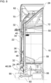
- Figure 8 shows how the cleaning fluid tank 56, preferably together with the filler neck 48 and the line 58, can be guided from below the motor vehicle 10 to the desired mounting position or removed from this (see double arrow in Figure 8 ).
- the cleaning fluid tank 56 is thus accessible and mountable from underneath the motor vehicle 10.
- the arrangement of the cleaning fluid tank 56 also offers the advantage that, in the event of a leak, the cleaning fluid does not flow downwards over sensitive components, but can drip directly onto the ground.
- the motor vehicle 10 may have a height-adjustable roof spoiler 62.
- the Figure 9 shows exemplary height settings of the roof spoiler 62.
- the steepest alignment of the roof spoiler 62 can be used, for example, when mounting or dismounting the roof spoiler on the roof 28.
- the mounting and dismounting (e.g. in case of damage) of the roof spoiler 62 can be carried out in this way without having to dismantle the possibly existing loading structure 14 is required.
- the steepest orientation can, for example, be a vertical or almost vertical orientation of the roof spoiler 62.
- the roof spoiler 62 is arranged on the roof 28.
- the roof spoiler 62 can be pivotably mounted on the roof 28 in the region of its front edge.
- the height of the roof spoiler 62 can be adjusted using the adjustment device 50.
- the adjustment device 50 can have a rail 64.
- the rail 64 is designed as an elongated hole.
- the rail 64 is vertically aligned.
- a longitudinal edge of the elongated hole can have several projections 66 arranged one above the other.
- the projections 66 can enable different possible height adjustments of the roof spoiler 62.
- the projections 66 can be designed, for example, as prongs, claws, or teeth.
- An elongated connecting element 68 (hidden in Figures 7 and 8 ) can be detachably attached, e.g., by means of a screw connection, to a desired projection 66 of the projections 66.
- the connecting element 68 connects the adjusting device 50 to the roof spoiler 62.
- the connecting element 68 can be pivotally attached to an inner side of the roof spoiler 62.
- the connecting element 68 is preferably designed as a rod, tube, or beam.
- the motor vehicle 10 can also have a trim part 70.
- the trim part 70 can be arranged between the roof spoiler 62 and the outer side panel 22 and, for example, bridge a gap between a lower edge of the roof spoiler 62 and the roof 28. The gap can be present depending on a height adjustment of the roof spoiler 62.
- the connecting element 68 can be arranged behind the trim part 70.
- the Figures 9 and 10 show the roof 28 of the motor vehicle 10.
- the roof 28 has a roof trench or recess 72.
- the recess 72 can extend across the entire width of the roof spoiler 62 or the roof 28.
- the recess 72 serves to partially accommodate the roof spoiler 62 and can also enable its pivoting for height adjustment.
- a front edge of the roof spoiler 62 dips ever deeper into the recess 72 as the roof spoiler 62 is increasingly tilted. This allows for a uniform and uninterrupted airflow to the roof spoiler 62 during operation.
- the recess 72 can have a curved or bent bottom surface that slopes downwards, at least in sections, toward both longitudinal outer sides of the motor vehicle 10, i.e., is directed diagonally downwards. This prevents water from accumulating on the roof 28. Instead, the water can simply flow away toward the longitudinal outer sides.
Landscapes
- Engineering & Computer Science (AREA)
- Mechanical Engineering (AREA)
- Chemical & Material Sciences (AREA)
- Combustion & Propulsion (AREA)
- Transportation (AREA)
- Water Supply & Treatment (AREA)
- Body Structure For Vehicles (AREA)
Description
Die Erfindung betrifft ein Kraftfahrzeug, vorzugsweise ein Nutzfahrzeug, mit einem Dachspoiler.The invention relates to a motor vehicle, preferably a commercial vehicle, with a roof spoiler.
Kraftfahrzeuge, insbesondere Lastkraftwagen, können einen höhenverstellbaren Dachspoiler aufweisen. Mittels der Höhenverstellung kann eine Ausrichtung des Dachspoilers bezüglich einer vorderen Oberkante eines Ladeaufbaus, eines Aufliegers oder eines Anhängers angepasst werden. Die Höhenverstellung erfolgt herkömmlich manuell an einer Rückwand eines Fahrerhauses des Lastkraftwagens.Motor vehicles, especially trucks, can have a height-adjustable roof spoiler. The height adjustment allows the roof spoiler to be aligned relative to the front upper edge of a loading body, semitrailer, or trailer. The height adjustment is traditionally performed manually on the rear wall of the truck's cab.
Kraftfahrzeuge können zur Reinigung der Windschutzscheibe eine Scheibenreinigungsanlage aufweisen. Die Scheibenreinigungsanlage kann Reinigungsdüsen, eine Pumpe und einen Tank aufweisen. Die Reinigungsdüsen sind auf die Windschutzscheibe gerichtet und können von der Pumpe mit einer Reinigungsflüssigkeit aus dem Tank versorgt werden. Für den Tank muss Bauraum vorgehalten werden. Zudem ist ein einfacher Zugang zu dem Tank zu dessen Befüllung vorteilhaft.Motor vehicles may be equipped with a windshield cleaning system for cleaning the windshield. The windshield cleaning system may include cleaning nozzles, a pump, and a tank. The cleaning nozzles are directed at the windshield and can be supplied with cleaning fluid from the tank by the pump. Space must be provided for the tank. Easy access to the tank for filling is also advantageous.
Herkömmliche Halterungen für höhenverstellbare Dachspoiler sind bspw. aus der
Zum Stand der Technik wird ferner auf die
Aus der
Die
Die
Die
Der Erfindung liegt die Aufgabe zu Grunde, ein alternatives und/oder verbessertes Kraftfahrzeug mit einem Dachspoiler, und vorzugsweise zusätzlich mit einer Scheibenreinigungsanlage, zu schaffen.The invention is based on the object of creating an alternative and/or improved motor vehicle with a roof spoiler, and preferably additionally with a windscreen cleaning system.
Die Aufgabe wird gelöst durch die Merkmale des unabhängigen Anspruchs. Vorteilhafte Weiterbildungen sind in den abhängigen Ansprüchen und der Beschreibung angegeben.The problem is solved by the features of the independent claim. Advantageous further developments are specified in the dependent claims and the description.
Gemäß einem Aspekt ist ein Kraftfahrzeug, vorzugsweise Nutzfahrzeug (z. B. Lastkraftwagen), offenbart. Das Kraftfahrzeug weist eine Karosserie und eine Außenseitenblende, die an einer Längsaußenseite des Kraftfahrzeugs angeordnet und zwischen einer Schließstellung und einer Öffnungsstellung bewegbar, vorzugsweise verschwenkbar, mit der Karosserie (z. B. direkt oder indirekt) verbunden ist, auf. Das Kraftfahrzeug weist einen (z. B. schwenkbarer) Dachspoiler und eine (z. B. manuelle) Verstelleinrichtung, mittels der der Dachspoiler höhenverstellbar ist, auf. Die Verstelleinrichtung ist in der Schließstellung der Außenseitenblende verdeckt hinter der Außenseitenblende angeordnet. Die Verstelleinrichtung ist in der Öffnungsstellung der Außenseitenblende von außen zugänglich.According to one aspect, a motor vehicle, preferably a commercial vehicle (e.g., a truck), is disclosed. The motor vehicle has a body and an outer side panel, which is arranged on a longitudinal outer side of the motor vehicle and is movable between a closed position and an open position, preferably pivotable, connected to the body (e.g., directly or indirectly). The motor vehicle has a (e.g., pivotable) roof spoiler and an (e.g., manual) adjustment device by means of which the roof spoiler can be adjusted in height. When the outer side panel is in the closed position, the adjustment device is concealed behind the outer side panel. When the outer side panel is in the open position, the adjustment device is accessible from the outside.
Vorteilhaft ist die Verstelleinrichtung so besonders einfach zugänglich. Andererseits ist die Verstelleinrichtung geschützt und optisch ansprechend hinter der Außenseitenblende angeordnet.This makes the adjustment mechanism particularly easy to access. On the other hand, the adjustment mechanism is protected and visually appealingly located behind the outer panel.
Erfindungsgemäß weist die Karosserie eine Längsseitenwand auf, und die Verstelleinrichtung ist an der Längsseitenwand angeordnet und/oder befestigt. Vorzugsweise kann die Längsseitenwand parallel zu einer Längsachse des Kraftfahrzeugs ausgerichtet sein und/oder in der Schließstellung der Außenseitenblende von der Außenseitenblende verdeckt und in der Öffnungsstellung der Außenseitenblende von außen zugänglich sein.According to the invention, the body has a longitudinal side wall, and the adjusting device is arranged and/or fastened to the longitudinal side wall. Preferably, the longitudinal side wall can be aligned parallel to a longitudinal axis of the motor vehicle and/or can be concealed by the outer side panel in the closed position of the outer side panel and accessible from the outside in the open position of the outer side panel.
In einem weiteren Ausführungsbeispiel weist die Verstelleinrichtung eine (z. B. vertikal ausgerichtete) Schiene auf, mittels der der Dachspoiler höhenverstellbar ist. Vorzugsweise kann die Schiene als ein Langloch ausgebildet sein und/oder mehrere übereinander angeordnete (z. B. zackenförmige, krallenförmige oder zahnförmige) Vorsprünge aufweisen, an denen der Dachspoiler mittelbar (z. B. mittels eines länglichen Verbindungselements) lösbar anbringbar ist, bevorzugt mittels einer Schraubverbindung.In a further embodiment, the adjustment device comprises a (e.g., vertically oriented) rail by means of which the roof spoiler is height-adjustable. The rail can preferably be configured as an elongated hole and/or comprise a plurality of superimposed (e.g., serrated, claw-shaped, or tooth-shaped) projections to which the roof spoiler can be detachably attached indirectly (e.g., by means of an elongated connecting element), preferably by means of a screw connection.
In einem weiteren Ausführungsbeispiel weist das Kraftfahrzeug ferner ein längliches (z. B. stangenförmiges, rohrförmiges oder balkenförmiges) Verbindungselement auf, das den Dachspoiler höhenverstellbar mit der Verstelleinrichtung verbindet und vorzugsweise verschwenkbar mit dem Dachspoiler verbunden ist. Optional kann das Kraftfahrzeug ferner ein Verkleidungsteil aufweisen, das zwischen dem Dachspoiler und der Außenseitenblende angeordnet ist, wobei das längliche Verbindungselement zumindest abschnittsweise verdeckt hinter dem Verkleidungsteil angeordnet ist. Damit kann der gesamte Verstellmechanismus für den Dachspoiler von außen uneinsichtig, geschützt und die Aerodynamik des Kraftfahrzeugs nicht negativ beeinflussend angeordnet sein.In a further exemplary embodiment, the motor vehicle further comprises an elongated (e.g., rod-shaped, tubular, or beam-shaped) connecting element that connects the roof spoiler to the adjustment device in a height-adjustable manner and is preferably pivotably connected to the roof spoiler. Optionally, the motor vehicle may further comprise a trim panel arranged between the roof spoiler and the outer side panel, wherein the elongated connecting element is arranged at least partially concealed behind the trim panel. Thus, the entire adjustment mechanism for the roof spoiler can be arranged in a manner that is not visible from the outside, protected, and does not negatively impact the aerodynamics of the motor vehicle.
In einer Ausführungsform weist die Karosserie ein Dach mit einer Vertiefung (z. B. Dachgraben) auf, und eine Vorderkante des Dachspoilers taucht bei einem Höherverstellen des Dachspoilers in die Vertiefung ein, z. B. zunehmend. Damit kann eine verbesserte Anströmung des Dachspoilers erreicht werden.In one embodiment, the body has a roof with a recess (e.g. roof ditch), and a leading edge of the roof spoiler emerges when the vehicle is raised of the roof spoiler into the recess, e.g., increasingly. This can improve the airflow to the roof spoiler.
In einer Ausführungsform ist der Dachspoiler zur Montage oder Demontage mittels der Verstelleinrichtung in eine im Wesentlichen senkrechte Ausrichtung verstellbar. Dies kann bspw. eine (De-) Montage erlauben, ohne dass bspw. ein Ladeaufbau des Kraftfahrzeugs demontiert werden muss.In one embodiment, the roof spoiler can be adjusted to a substantially vertical orientation for installation or removal using the adjustment device. This can, for example, allow for installation (or removal) without having to dismantle a vehicle's cargo structure.
In einer Weiterbildung erstreckt sich die Vertiefung über eine gesamte Breite des Dachs. Vorzugsweise kann eine Bodenfläche der Vertiefung gebogen, gekrümmt und/oder zu beiden Längsaußenseiten des Kraftfahrzeugs hin abfallend sein (bzw. ein Gefälle aufweisen). Damit kann Wasser einfach abfließen und bleibt nicht auf dem Dach stehen.In a further development, the recess extends across the entire width of the roof. Preferably, a bottom surface of the recess can be curved, bent, and/or slope down toward both outer longitudinal sides of the vehicle (or have a gradient). This allows water to drain away easily and does not remain on the roof.
In einer Ausführungsform weist das Kraftfahrzeug ferner eine Scheibenreinigungsanlage (z. B. mit einer Reinigungsdüse für eine Windschutzscheibe und/oder eine Scheibe eines Scheinwerfers) mit einem Reinigungsflüssigkeitstank und einem Einfüllstutzen zum Befüllen des Reinigungsflüssigkeitstanks auf. Der Einfüllstutzen ist in der Schließstellung der Außenseitenblende verdeckt hinter der Außenseitenblende angeordnet und der Einfüllstutzen ist in der Öffnungsstellung der Außenseitenblende von außen zugänglich. Damit kann der Einfüllstutzen von außen uneinsichtig, geschützt und die Aerodynamik des Kraftfahrzeugs nicht negativ beeinflussend angeordnet sein. Hinter der Außenseitenblende können somit mehrere Funktionen verborgen sein. Zusätzlich ergeben sich neue Möglichkeiten für die Anordnung des Reinigungsflüssigkeitstanks.In one embodiment, the motor vehicle further comprises a windshield washer system (e.g., with a cleaning nozzle for a windshield and/or a headlight lens) with a washer fluid tank and a filler neck for filling the washer fluid tank. When the outer side panel is in the closed position, the filler neck is concealed behind the outer side panel, and when the outer side panel is in the open position, the filler neck is accessible from the outside. This allows the filler neck to be concealed from the outside, protected, and positioned in a way that does not negatively impact the aerodynamics of the motor vehicle. Several functions can thus be concealed behind the outer side panel. This also opens up new possibilities for arranging the washer fluid tank.
In einer Weiterbildung ist der Einfüllstutzen an der Längsseitenwand angeordnet und/oder befestigt, vorzugsweise in einer Öffnung der Längsseitenwand, bevorzugt unterhalb der Verstelleinrichtung.In a further development, the filler neck is arranged and/or fastened to the longitudinal side wall, preferably in an opening of the longitudinal side wall, preferably below the adjusting device.
In einer weiteren Ausführungsform ist der Reinigungsflüssigkeitstank von unterhalb des Kraftfahrzeugs zugänglich und/oder montierbar (z. B. einbaubar, ausbaubar, wechselbar). Damit kann die Montage und ggf. einen Austausch des Reinigungsflüssigkeitstanks vereinfacht werden.In a further embodiment, the cleaning fluid tank is accessible and/or mountable (e.g., installable, removable, replaceable) from underneath the motor vehicle. This simplifies the installation and, if necessary, replacement of the cleaning fluid tank.
In einer Ausführungsvariante ist der Reinigungsflüssigkeitstank zumindest teilweise in einem Abschnitt zwischen einem Innenkotflügel des Kraftfahrzeugs und einem Außenkotflügel des Kraftfahrzeugs angeordnet. Alternativ oder zusätzlich ist der Reinigungsflüssigkeitstank bezüglich einer Vorwärtsfahrrichtung des Kraftfahrzeugs hinter einer Tür des Kraftfahrzeugs angeordnet. Alternativ oder zusätzlich ist der Reinigungsflüssigkeitstank innen an bzw. von einer Rückwand der Karosserie angeordnet. Somit kann der Reinigungsflüssigkeitstank auf vorteilhafte Weise in einem zuvor ungenutzten Raum der Karosserie angeordnet sein.In one embodiment, the cleaning fluid tank is arranged at least partially in a section between an inner fender of the motor vehicle and an outer fender of the motor vehicle. Alternatively or additionally, the cleaning fluid tank is arranged behind a door of the motor vehicle with respect to a forward direction of travel of the motor vehicle. Alternatively or additionally, the cleaning fluid tank is arranged inside on or by a rear wall of the body. Thus, the cleaning fluid tank can advantageously be arranged in a previously unused space in the body.
In einer weiteren Ausführungsvariante weist das Kraftfahrzeug ferner mindestens ein Werkzeug (z. B. Abschleppöse, Wischstange, Radmutternschlüssel, Wagenheber), mindestens einen Behälter und/oder mindestens ein Staufach auf, das bzw. der in der Schließstellung der Außenseitenblende von der Außenseitenblende verdeckt ist und in der Öffnungsstellung der Außenseitenblende von außen zugänglich ist.In a further embodiment, the motor vehicle further comprises at least one tool (e.g. towing eye, wiper rod, wheel nut wrench, jack), at least one container and/or at least one storage compartment which is concealed by the outer side panel in the closed position of the outer side panel and is accessible from the outside in the open position of the outer side panel.
In einem Ausführungsbeispiel ist die Außenseitenblende mittels eines innerhalb der Karosserie zugänglichen Bowdenzugs aus der Schließstellung entriegelbar und/oder bewegbar.In one embodiment, the outer side panel can be unlocked and/or moved from the closed position by means of a Bowden cable accessible within the body.
In einem weiteren Ausführungsbeispiel ist die Karosserie als eine Fahrerhauskarosserie eines Lastkraftwagens ausgeführt.In a further embodiment, the body is designed as a cab body of a truck.
In einer Ausführungsform ist die Außenseitenblende als ein Sideflap ausgeführt.In one embodiment, the outer side panel is designed as a side flap.
In einer weiteren Ausführungsform ist die Außenseitenblende in einer Schließstellung schräg nach außen angewinkelt zu einer Längsachse des Kraftfahrzeugs angeordnet, sodass vorzugsweise eine Hinterkante der Außenseitenblende mit einer Seitenwand eines Ladeaufbaus eines Anhängers oder eines Aufliegers des Kraftfahrzeugs ausgerichtet ist, bevorzugt im Wesentlichen bündig.In a further embodiment, the outer side panel is arranged in a closed position at an angle obliquely outwards to a longitudinal axis of the motor vehicle, so that preferably a rear edge of the outer side panel is aligned with a side wall of a loading structure of a trailer or semi-trailer of the motor vehicle, preferably substantially flush.
In einer Ausführungsvariante ist die Außenseitenblende oberhalb von einem Außenkotflügel und/oder einer Vorderachse des Kraftfahrzeugs angeordnet.In one embodiment, the outer side panel is arranged above an outer fender and/or a front axle of the motor vehicle.
In einer weiteren Ausführungsvariante erstreckt sich die Außenseitenblende zwischen einem Außenkotflügel des Kraftfahrzeugs und einem Dach des Kraftfahrzeugs.In a further embodiment, the outer side panel extends between an outer fender of the motor vehicle and a roof of the motor vehicle.
In einem Ausführungsbeispiel ist die Außenseitenblende bezüglich einer Vorwärtsfahrtrichtung des Kraftfahrzeugs von der Schließstellung nach hinten in die Öffnungsstellung schwenkbar.In one embodiment, the outer side panel can be pivoted from the closed position backwards into the open position with respect to a forward direction of travel of the motor vehicle.
In einem weiteren Ausführungsbeispiel weist die Außenseitenblende bezüglich einer Vorwärtsfahrtrichtung des Kraftfahrzeugs eine gerade Hinterkante und eine zumindest abschnittsweise gekrümmte Vorderkante auf.In a further embodiment, the outer side panel has a straight rear edge and a front edge that is at least partially curved with respect to a forward direction of travel of the motor vehicle.
In einem weiteren Ausführungsbeispiel weist das Kraftfahrzeug eine Tür (z. B. Fahrertür oder Beifahrertür) auf, die bewegbar mit der Karosserie verbunden ist. Die Außenseitenblende ist bezüglich einer Vorwärtsfahrtrichtung des Kraftfahrzeugs hinter der Tür angeordnet.In a further embodiment, the motor vehicle has a door (e.g., driver's door or passenger door) that is movably connected to the body. The outer side panel is arranged behind the door with respect to a forward direction of travel of the motor vehicle.
Die zuvor beschriebenen bevorzugten Ausführungsformen und Merkmale der Erfindung sind beliebig miteinander kombinierbar. Weitere Einzelheiten und Vorteile der Erfindung werden im Folgenden unter Bezug auf die beigefügten Zeichnungen beschrieben. Es zeigen:
- Figur 1
- eine Seitenansicht eines vorderen Abschnitts eines beispielhaften Kraftfahrzeugs;
- Figur 2
- eine weitere Seitenansicht des vorderen Abschnitts des beispielhaften Kraftfahrzeugs mit einer aufgeschwenkten Außenseitenblende;
- Figur 3
- eine Detailansicht eines Details A aus
Figur 2 ; - Figur 4
- eine Horizontalschnittansicht durch die Außenseitenblende des Kraftfahrzeugs auf Höhe eines unteren Scharniers, wobei die Außenseitenblende in einer Öffnungsstellung und einer Schließstellung dargestellt ist;
- Figur 5
- eine weitere Horizontalschnittansicht durch die Außenseitenblende des beispielhaften Kraftfahrzeugs auf Höhe einer Verriegelungseinrichtung, wobei die Außenseitenblende in einer Öffnungsstellung und einer Schließstellung dargestellt ist;
- Figur 6
- eine Rückansicht einer Fahrerseite des beispielhaften Kraftfahrzeugs;
- Figur 7
- eine weitere Rückansicht der Fahrerseite des beispielhaften Kraftfahrzeugs ohne Darstellung eines Wandelements einer Rückwand des Kraftfahrzeugs;
- Figur 8
- eine weitere Rückansicht der Fahrerseite des beispielhaften Kraftfahrzeugs mit einer schematischen Illustration einer (De-)Montage eines Reinigungsflüssigkeitsbehälters einer Scheibenwaschanlage des beispielhaften Kraftfahrzeugs;
- Figur 9
- eine Vertikalschnittansicht entlang einer Längsachse des beispielhaften Kraftfahrzeugs durch einen höhenverstellbaren Dachspoiler des Kraftfahrzeugs, wobei der Dachspoiler in drei unterschiedlichen Höheneinstellungen dargestellt ist; und
Figur 10- eine perspektivische Rückansicht auf ein Dach des beispielhaften Kraftfahrzeugs ohne Darstellung eines Dachspoilers des Kraftfahrzeugs.
- Figure 1
- a side view of a front portion of an exemplary motor vehicle;
- Figure 2
- another side view of the front portion of the exemplary motor vehicle with an outer side panel swung open;
- Figure 3
- a detailed view of a detail A from
Figure 2 ; - Figure 4
- a horizontal sectional view through the outer side panel of the motor vehicle at the level of a lower hinge, the outer side panel being shown in an open position and a closed position;
- Figure 5
- a further horizontal sectional view through the outer side panel of the exemplary motor vehicle at the level of a locking device, wherein the outer side panel is shown in an open position and a closed position;
- Figure 6
- a rear view of a driver's side of the exemplary motor vehicle;
- Figure 7
- a further rear view of the driver's side of the exemplary motor vehicle without showing a wall element of a rear wall of the motor vehicle;
- Figure 8
- a further rear view of the driver's side of the exemplary motor vehicle with a schematic illustration of a (dis)assembly of a cleaning fluid container of a windshield washer system of the exemplary motor vehicle;
- Figure 9
- a vertical sectional view along a longitudinal axis of the exemplary motor vehicle through a height-adjustable roof spoiler of the motor vehicle, wherein the roof spoiler is shown in three different height settings; and
- Figure 10
- a perspective rear view of a roof of the exemplary motor vehicle without depicting a roof spoiler of the motor vehicle.
Die in den Figuren gezeigten Ausführungsformen stimmen zumindest teilweise überein, so dass ähnliche oder identische Teile mit den gleichen Bezugszeichen versehen sind und zu deren Erläuterung auch auf die Beschreibung der anderen Ausführungsformen bzw. Figuren verwiesen wird, um Wiederholungen zu vermeiden.The embodiments shown in the figures correspond at least partially, so that similar or identical parts are provided with the same reference numerals and for their explanation reference is also made to the description of the other embodiments or figures in order to avoid repetition.
Die
Wie insbesondere die
Das Kraftfahrzeug 10 kann einen Ladeaufbau 14 zum Transportieren von Gütern aufweisen. Der Ladeaufbau 14 ist hinter der Karosserie 12 angeordnet. Der Ladeaufbau 14 kann eine Vorderwand 18 aufweisen, die direkt an eine Rückwand 16 der Karosserie 12 angrenzt. Es ist auch möglich, dass die Vorderwand 18 des Ladeaufbaus 14 beabstandet zu der Rückwand 16 der Karosserie 12 ist. Der Ladeaufbau 14 kann auf dem Fahrzeugrahmen abgestützt sein. Es ist beispielsweise auch möglich, dass das Kraftfahrzeug 10 alternativ zu dem Ladeaufbau 14 einen gezogenen Anhänger oder Sattelauflieger aufweist, dessen Vorderwand zweckmäßig beabstandet zu der Rückwand 16 angeordnet ist.The
Das Kraftfahrzeug 10 weist mindestens eine Tür 20 auf. Die Tür 20 gewährt Zugang zu einem Innenraum des Kraftfahrzeugs 10. Die mindestens eine Tür 20 umfasst zweckmäßig eine Fahrertür auf einer Fahrerseite des Kraftfahrzeugs 10 und eine Beifahrertür auf einer Beifahrerseite des Kraftfahrzeugs 10. Die Tür 20 ist bewegbar, vorzugsweise verschwenkbar, mit der Karosserie 12 zum Öffnen der Tür 20 verbunden.The
Das Kraftfahrzeug 10 weist mindestens eine Außenseitenblende 22 auf. Die Außenseitenblende 22 ist als eine längliche Blende ausgeführt. Eine Längsachse der Außenseitenblende 22 verläuft zweckmäßig parallel zu einer Vertikalachse/Hochachse des Kraftfahrzeugs 10. Bevorzugt ist die Außenseitenblende 22 bezüglich der Vorwärtsfahrtrichtung des Kraftfahrzeugs 10 hinter der Tür 20 angeordnet. Die Außenseitenblende 22 ist oberhalb von einem Außenkotflügel 24 einer Vorderachse 26 des Kraftfahrzeugs 10 angeordnet. Im Einzelnen kann sich die Außenseitenblende 22 zwischen dem Außenkotflügel 24 und einem Dach 28 des Kraftfahrzeugs 10 erstrecken. Eine weitere Außenseitenblende 22 kann auf der gegenüberliegenden Fahrzeugseite, zum Beispiel der Beifahrerseite, entsprechend angeordnet und ausgebildet sein.The
Die Außenseitenblende 22 ist beweglich mit der Karosserie 12 verbunden, unmittelbar oder mittelbar. Vorzugsweise ist die Außenseitenblende 22 verschwenkbar mit der Karosserie 12 verbunden. Die Außenseitenblende 22 kann zwischen einer Schließstellung, z. B. Einschwenkstellung, und einer Öffnungsstellung, z. B. Ausschwenkstellung, bewegt werden. Die
Die Außenseitenblende 22 ist zweckmäßig als ein sogenannter Sideflap ausgeführt. Eine Aufgabe der Außenseitenblende 22 besteht somit insbesondere in der verbesserten Aerodynamik des Kraftfahrzeugs 10, wobei insbesondere die Umströmung des Kraftfahrzeugs 10 beim Übergang zum Ladeaufbau 14 (oder Anhänger oder Auflieger) verbessert wird. Zweckmäßig kann die Außenseitenblende 22 daher in der Schließstellung schräg nach außen angewinkelt zu einer Längsachse des Kraftfahrzeugs 10 angeordnet sein. Eine Hinterkante der Außenseitenblende 22 kann so mit einer Vorderkante einer Seitenwand 30 des Ladeaufbaus 14 ausgerichtet sein, vorzugsweise bündig. Damit kann der Übergang zwischen dem schmaleren Fahrerhaus und den breiteren Ladeaufbau 14 aerodynamisch verbessert werden. In Ausführungsformen, in denen beispielsweise der Ladeaufbau 14 beabstandet zu der Karosserie 12 ist oder ein Anhänger oder ein Sattelauflieger von dem Kraftfahrzeug 10 gezogen wird, kann die als Sideflap ausgeführte Außenseitenblende 22 zusätzlich oder alternativ einen Abstand zwischen der Rückwand 16 der (Fahrerhaus-) Karosserie 12 und der Vorderwand 18 des Ladeaufbaus 14, des Anhängers oder Sattelaufliegers zumindest teilweise, vorzugsweise im Wesentlichen vollständig, überbrücken. Die Außenseitenblende 22 kann daher entgegen einer Vorwärtsfahrtrichtung des Kraftfahrzeugs 10 über die Rückwand 16 überstehen oder hinter der Rückwand 16 angeordnet sein.The
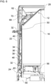
Die
Im dargestellten Ausführungsbeispiel ist die Außenseitenblende 22 mittels zweier Scharniere 32 schwenkbar mit einer äußeren Längsseitenwand 34 der Karosserie 12 verbunden. Die Außenseitenblende 22 ist mittels einer Verriegelungseinrichtung 36 in der Schließstellung verriegelbar. Die Verriegelungseinrichtung 36 kann zweckmäßig mittels eines Bowdenzugs 38 zum Freigeben der Außenseitenblende 22 entriegelt werden. Bevorzugt ist der Bowdenzug 38 von innerhalb des Kraftfahrzeugs 10 betätigbar. Die Außenseitenblende 22 auf der anderen Fahrzeugseite (z. B. Beifahrerseite) kann vorzugsweise mit einem anderen, einfacheren Mechanismus entriegelt werden.In the illustrated embodiment, the
Die
Das Scharnier 32 ist einerseits an einer Innenseite der Außenseitenblende 22 angebracht. Andererseits ist das Scharnier 32 an der Längsseitenwand 34 der Karosserie 12 angebracht, zum Beispiel mittels eines Haltewinkels 40. Bevorzugt ist die Außenseitenblende 22 lösbar an der Längsseitenwand 34 angebracht, zum Beispiel mittels mindestens einer Schraubverbindung.The
Das Scharnier 32 ist an einer Hinterkante der Außenseitenblende 22 angeordnet. Damit kann die Außenseitenblende 22 aus der Schließstellung entgegen der Vorwärtsfahrtrichtung des Kraftfahrzeugs 10 nach hinten in die Öffnungsstellung verschwenkt werden. Eine derartige Anbindung kann dadurch bevorzugt sein, dass eine Vorderkante der Außenseitenblende 22 zumindest abschnittsweise gekrümmt ist, die Hinterkante der Außenseitenblende 22 hingegen gradlinig ausgeführt ist.The
In der Schließstellung kann die Außenseitenblende 22 zusätzlich an der Längsseitenwand 34 durch mindestens ein Halteelement 42, vorzugsweise gedämpft, abgestützt und/oder zentriert sein. Das Halteelement 42 kann beispielsweise stiftförmig oder tropfenförmig sein und in eine entsprechende Öffnung in der Außenseitenblende 22 eingreifen, wie in
Die
Die Verriegelungseinrichtung 36 kann ein beispielsweise bolzenförmiges Verriegelungselement 44 und eine Aufnahme bzw. Falle 46 für das Verriegelungselement 44 aufweisen. Das Verriegelungselement 44 ist an einer Innenseite der Außenseitenblende 22 angebracht. Die Falle 46 ist an der Längsseitenwand 34 angebracht. Die Falle 46 kann mittels des Bowdenzugs 38 (siehe auch
Es wird erneut auf die
Beispielsweise kann ein Einfüllstutzen 48 hinter der Außenseitenblende 22 angeordnet sein. Der Einfüllstutzen 48 kann in einer (Durchgangs-)Öffnung der Längsseitenwand 34 angebracht sein. Der Einfüllstutzen 48 kann mittels eines lösbaren Deckels verschließbar sein. Es ist auch möglich, dass eine Verstelleinrichtung 50 hinter der Außenseitenblende 22 angeordnet und an der Längsseitenwand 34 angebracht ist. Es ist ebenfalls möglich, dass alternativ oder zusätzlich mindestens eine andere Komponente 52 hinter der Außenseitenblende 22 angeordnet und beispielsweise an der Längsseitenwand 34 angebracht ist, wie schematisch in
Unter Bezugnahme auf den genannten Einfüllstutzen 48 ist nachfolgend auf die
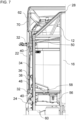
Das Kraftfahrzeug 10 kann eine Scheibenreinigungsanlage 54 aufweisen. Die Scheibenreinigungsanlage 54 kann mindestens eine Reinigungsdüse aufweisen, die zum Versprühen einer Reinigungsflüssigkeit auf eine Windschutzscheibe des Kraftfahrzeugs und/oder eine Scheibe eines Scheinwerfers des Kraftfahrzeugs 10 angeordnet ist. Die Scheibenreinigungsanlage 54 weist ferner eine Pumpe (nicht dargestellt), einen Reinigungsflüssigkeitstank 56 und den Einfüllstutzen 48 auf. Der Einfüllstutzen 48 ist über eine Leitung 58, zum Beispiel Rohrleitung oder Schlauchleitung, mit dem Reinigungsflüssigkeitstank verbunden. Die Pumpe kann eine Reinigungsflüssigkeit aus dem Reinigungsflüssigkeitstank 56 absaugen und zu der mindestens einen Reinigungsdüse der Scheibenreinigungsanlage 54 zuführen.The
Eine derartige Anordnung des Einfüllstutzens 48 bietet den Vorteil einer leichten Zugänglichkeit. Zusätzlich kann der Reinigungsflüssigkeitstank 56 in einem zuvor ungenutzten Raum sicher innerhalb der Karosserie 12 angeordnet werden. Der Reinigungsflüssigkeitstank 56 ist zumindest teilweise in einem Abschnitt zwischen einem Innenkotflügel 60 des Kraftfahrzeugs 10 und dem Außenkotflügel 24 des Kraftfahrzeugs angeordnet. Der Reinigungsflüssigkeitstank 56 ist bezüglich der Vorwärtsfahrrichtung der Kraftfahrzeugs10 hinter der Tür 20 angeordnet, vorzugsweise innen an der Rückwand 16 der Karosserie 12.Such an arrangement of the
Diese Anordnung des Reinigungsflüssigkeitstanks 56 kann den weiteren Vorteil einer einfachen Montage und Demontage (zum Beispiel in einem Reparaturfall) des Reinigungsflüssigkeitstanks 56 ermöglichen. Hierzu wird auf die
Unter Bezugnahme auf die genannte Verstelleinrichtung 50 ist nachfolgend auf die
Das Kraftfahrzeug 10 kann einen höhenverstellbaren Dachspoiler 62 aufweisen. Die
Der Dachspoiler 62 ist auf dem Dach 28 angeordnet. Der Dachspoiler 62 kann im Bereich seiner Vorderkante schwenkbar an dem Dach 28 angebracht sein. Mittels der Verstelleinrichtung 50 kann eine Höhenverstellung des Dachspoilers 62 vorgenommen werden. Durch die Anordnung der Verstelleinrichtung 50 hinter der Außenseitenblende 22 kann eine gute Zugänglichkeit der Verstelleinrichtung 50 gewährleistet werden, wenn die Außenseitenblende 22 in die Öffnungsstellung bewegt wird. Es kann auf beiden Längsaußenseiten des Kraftfahrzeugs 10 jeweils eine Verstelleinrichtung 50 hinter einer entsprechenden Außenseitenblende 22 angeordnet sein.The
Die Verstelleinrichtung 50 kann eine Schiene 64 aufweisen. Die Schiene 64 ist als Langloch ausgeführt. Die Schiene 64 ist vertikal ausgerichtet. Eine Längskante des Langlochs kann mehrere übereinander angeordnete Vorsprünge 66 aufweisen. Die Vorsprünge 66 können unterschiedlich mögliche Höheneinstellungen des Dachspoilers 62 ermöglichen. Die Vorsprünge 66 können beispielsweise als Zacken, Krallen oder Zähne ausgeführt sein.The
Ein längliches Verbindungselement 68 (ausgeblendet in
Das Kraftfahrzeug 10 kann zudem ein Verkleidungsteil 70 aufweisen. Das Verkleidungsteil 70 kann zwischen dem Dachspoiler 62 und der Außenseitenblende 22 angeordnet sein und bspw. einen Spalt zwischen einer Unterkante des Dachspoilers 62 und dem Dach 28 überbrücken. Der Spalt kann in Abhängigkeit von einer Höheneinstellung des Dachspoilers 62 vorhanden sein. Das Verbindungselement 68 kann hinter dem Verkleidungsteil 70 angeordnet sein. Damit ist der gesamte Mechanismus zur Höhenverstellung des Dachspoilers optisch ansprechend und vor Witterungseinflüssen geschützt von außen nicht sichtbar angeordnet. Erst beim Bewegen der Außenseitenblende 22 in die Öffnungsstellung wird die Verstelleinrichtung 50 und ein unterer Abschnitt des Verbindungselements 68 sichtbar und zugängig.The
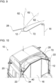
Die
Das Dach 28 weist einen Dachgraben bzw. eine Vertiefung 72 auf. Die Vertiefung 72 kann sich über eine gesamte Breite des Dachspoilers 62 bzw. des Dachs 28 erstrecken. Die Vertiefung 72 dient zur teilweisen Aufnahme des Dachspoilers 62 und kann zudem dessen Verschwenkbarkeit für die Höhenverstellung ermöglichen. Eine Vorderkante des Dachspoilers 62 taucht bei zunehmender Schrägstellung des Dachspoilers 62 immer tiefer in die Vertiefung 72 ein. Dadurch kann eine gleichmäßige und unterbrechungsfreie Anströmung des Dachspoilers 62 im Betrieb erreicht werden.The
Die Vertiefung 72 kann eine gebogene oder gekrümmte Bodenfläche aufweisen, die zu beiden Längsaußenseiten des Kraftfahrzeugs 10 hin nach unten zumindest abschnittsweise abfällt, d.h. schräg nach unten gerichtet ist. So kann verhindert werden, dass Wasser auf dem Dach 28 stehenbleibt. Stattdessen kann das Wasser einfach zu den Längsaußenseiten hin abfließen.The
- 1010
- Kraftfahrzeugmotor vehicle
- 1212
- Karosseriebody
- 1414
- LadeaufbauLoading structure
- 1616
- Rückwandback wall
- 1818
- Vorderwandfront wall
- 2020
- Türdoor
- 2222
- AußenseitenblendeOutside panel
- 2424
- Außenkotflügelouter fenders
- 2626
- Vorderachsefront axle
- 2828
- DachRoof
- 3030
- Seitenwandside wall
- 3232
- Scharnierhinge
- 3434
- LängsseitenwandLong side wall
- 3636
- VerriegelungseinrichtungLocking device
- 3838
- BowdenzugBowden cable
- 4040
- HaltewinkelBracket
- 4242
- HaltelementHolding element
- 4444
- VerriegelungselementLocking element
- 4646
- Falletrap
- 4848
- EinfüllstutzenFiller neck
- 5050
- Verstelleinrichtungadjustment device
- 5252
- Komponentecomponent
- 5454
- ScheibenreinigungsanlageWindscreen washer system
- 5656
- ReinigungsflüssigkeitstankCleaning fluid tank
- 5858
- LeitungLine
- 6060
- Innenkotflügelinner fender
- 6262
- Dachspoilerroof spoiler
- 6464
- Schienerail
- 6666
- Vorsprungprojection
- 6868
- Verbindungselementconnecting element
- 7070
- Verkleidungsteiltrim part
- 7272
- VertiefungDeepening
Claims (14)
- A motor vehicle (10), preferably a commercial vehicle, comprising:a vehicle body (12);an outer side panel (22), which is arranged at a longitudinal outer side of the motor vehicle (10) and is connected to the vehicle body (12) so as to be movable, preferably pivotable, between a closed position and an open position;a roof spoiler (62); andan adjusting device (50), by means of which the roof spoiler (62) is adjustable in height, wherein the adjusting device (50) is arranged concealed behind the outer side panel (22) in the closed position of the outer side panel (22) and the adjusting device (50) is accessible from the outside in the open position of the outer side panel (22),
wherein:the vehicle body (12) comprises a longitudinal side wall (34); andthe adjusting device (50) is arranged and/or secured on the longitudinal side wall (34). - The motor vehicle (10) according to claim 1, wherein:
the adjusting device (50) comprises a rail (64) by means of which the roof spoiler (62) is adjustable in height, wherein preferably:the rail (64) is configured as an elongated hole; and/orthe rail (64) comprises a plurality of projections (66) arranged one above the other, to which the roof spoiler (62) can be detachably attached indirectly, preferably by means of a screw connection. - The motor vehicle (10) according to one of the preceding claims, further comprising:an elongate connecting element (68), which connects the roof spoiler (62) to the adjusting device (50) in a height-adjustable manner and is preferably connected to the roof spoiler (62) in a pivotable manner; anda panelling member (70) which is arranged between the roof spoiler (62) and the outer side panel (22), wherein the elongate connecting element (68) is arranged at least partially concealed behind the panelling member (70).
- The motor vehicle (10) according to one of the preceding claims, wherein:the vehicle body (12) comprises a roof (28) with a recess (72) and a front edge of the roof spoiler (62) dips into the recess (72) when the roof spoiler (62) is raised; and/orthe roof spoiler (62) is adjustable into a substantially vertical orientation for assembly or disassembly by means of the adjusting device (50).
- The motor vehicle (10) according to claim 4, wherein:the recess (72) extends over an entire width of the roof (28); anda bottom surface of the recess (72) is bent, curved, and/or sloping towards both longitudinal outer sides of the motor vehicle (10).
- The motor vehicle (10) according to one of the preceding claims, further comprising:
a windscreen cleaning system (54) with a cleaning fluid tank (56) and a filler nozzle (48) for filling the cleaning fluid tank (56), wherein the filler nozzle (48) is arranged concealed behind the outer side panel (22) in the closed position of the outer side panel (22) and the filler nozzle (48) is accessible from the outside in the open position of the outer side panel (22). - The motor vehicle (10) according to claim 6, wherein:
the filler nozzle (48) is arranged and/or fastened on the longitudinal side wall (34), preferably in an opening of the longitudinal side wall (34). - The motor vehicle (10) according to claim 6 or claim 7, wherein:the cleaning fluid tank (56) is accessible and/or mountable from underneath the motor vehicle (10); and/orthe cleaning fluid tank (56) is arranged at least partially in a section between an inner mudguard (60) of the motor vehicle (10) and an outer mudguard (24) of the motor vehicle (10); and/orthe cleaning fluid tank (56) is arranged behind a door (20) of the motor vehicle (10) with respect to a forward travelling direction of the motor vehicle (10); and/orthe cleaning fluid tank (56) is arranged on the inside of a rear wall (16) of the vehicle body (12).
- The motor vehicle (10) according to one of the preceding claims, further comprisingat least one tool (52), which is concealed by the outer side panel (22) in the closed position of the outer side panel (22) and is accessible from the outside in the open position of the outer side panel (22); and/orat least one container (52), which is concealed by the outer side panel (22) in the closed position of the outer side panel (22) and is accessible from the outside in the open position of the outer side panel (22); and/orat least one storage compartment (52), which is concealed by the outer side panel (22) in the closed position of the outer side panel (22) and is accessible from the outside in the open position of the outer side panel (22).
- The motor vehicle (10) according to one of the preceding claims, wherein:
the outer side panel (22) is unlockable and/or movable from the closed position by means of a Bowden cable (38) accessible within the vehicle body (12). - The motor vehicle (10) according to one of the preceding claims, wherein:
the vehicle body (12) is configured as a cab body of a lorry. - The motor vehicle (10) according to one of the preceding claims, wherein:the outer side panel (22) is configured as a sideflap; and/orthe outer side panel (22) is arranged in a closed position angled outwards at an angle to a longitudinal axis of the motor vehicle (10), so that preferably a rear edge of the outer side panel (22) is aligned with a side wall (30) of a cargo body (14), a trailer, or a semi-trailer of the motor vehicle (10), preferably substantially flush.
- The motor vehicle (10) according to one of the preceding claims, wherein:the outer side panel (22) is arranged above an outer mudguard (24) and/or a front axle (26) of the motor vehicle (10); and/orthe outer side panel (22) extends between an outer mudguard (24) of the motor vehicle (10) and a roof (28) of the motor vehicle (10).
- The motor vehicle (10) according to one of the preceding claims, wherein:the outer side panel (22) is pivotable rearwardly from the closed position into the open position with respect to a forward travelling direction of the motor vehicle (10); and/orthe outer side panel (22) comprises a straight rear edge and an at least partially curved front edge with respect to a forward travelling direction of the motor vehicle (10); and/orthe motor vehicle (10) comprises a door (20), which is movably connected to the vehicle body (12), and the outer side panel (22) is arranged behind the door (20) with respect to a forward travelling direction of the motor vehicle (10).
Applications Claiming Priority (2)
| Application Number | Priority Date | Filing Date | Title |
|---|---|---|---|
| DE102019008489.6A DE102019008489A1 (en) | 2019-12-06 | 2019-12-06 | Motor vehicle with roof spoiler |
| PCT/EP2020/083039 WO2021110450A1 (en) | 2019-12-06 | 2020-11-23 | Motor vehicle with roof spoiler |
Publications (3)
| Publication Number | Publication Date |
|---|---|
| EP4069578A1 EP4069578A1 (en) | 2022-10-12 |
| EP4069578B1 true EP4069578B1 (en) | 2025-04-16 |
| EP4069578C0 EP4069578C0 (en) | 2025-04-16 |
Family
ID=73544195
Family Applications (1)
| Application Number | Title | Priority Date | Filing Date |
|---|---|---|---|
| EP20811606.1A Active EP4069578B1 (en) | 2019-12-06 | 2020-11-23 | Motor vehicle with roof spoiler |
Country Status (5)
| Country | Link |
|---|---|
| EP (1) | EP4069578B1 (en) |
| KR (1) | KR20220108117A (en) |
| CN (1) | CN114746328A (en) |
| DE (1) | DE102019008489A1 (en) |
| WO (1) | WO2021110450A1 (en) |
Families Citing this family (1)
| Publication number | Priority date | Publication date | Assignee | Title |
|---|---|---|---|---|
| DE102023111074A1 (en) | 2023-04-28 | 2024-10-31 | Quantron Ag | Spoiler device, spoiler arrangement, vehicle and use |
Family Cites Families (19)
| Publication number | Priority date | Publication date | Assignee | Title |
|---|---|---|---|---|
| GB2069941B (en) * | 1980-02-02 | 1983-11-16 | Motor Panels Coventry Ltd | Vehicle cabs having airflow defelctors on their roofs |
| US4779915A (en) * | 1987-04-27 | 1988-10-25 | Straight Gary D | Air foil system |
| DE3737380A1 (en) * | 1987-11-04 | 1989-05-18 | Iveco Magirus | Side panel for the purpose of improving the guidance of air between the driver's cab and semitrailer |
| DE3800742A1 (en) * | 1988-01-13 | 1989-03-23 | Daimler Benz Ag | Driver's cab for lorries |
| US4904015A (en) * | 1988-08-11 | 1990-02-27 | The Goodyear Tire & Rubber Company | Air deflection system |
| DE19825252A1 (en) * | 1998-06-05 | 1999-12-09 | Fritzmeier Composite Gmbh & Co | Vertically adjustable wind deflector for motor vehicles |
| AT407628B (en) * | 1999-04-08 | 2001-05-25 | Steyr Nutzfahrzeuge | BRACKET FOR A ROOF SPOILER ARRANGED ON THE CAB OF A TRUCK |
| US6428084B1 (en) * | 2001-04-24 | 2002-08-06 | Richard M. Liss | Fuel-efficient tractor-trailer system |
| FR2875197A1 (en) * | 2004-09-14 | 2006-03-17 | Renault Sas | MOTOR VEHICLE HAVING A WINDOW LAYER DEVICE |
| US7637557B2 (en) * | 2005-02-22 | 2009-12-29 | Volvo Lastvagnar Ab | Cab for a motor-driven tractor vehicle |
| AU2007210992A1 (en) * | 2006-01-31 | 2007-08-09 | Alcoa Inc. | Aerodynamic structures for tractor to trailer junction |
| DE102007036335A1 (en) * | 2007-08-02 | 2009-03-05 | Man Nutzfahrzeuge Ag | Roof spoiler arrangement for commercial vehicle cabs |
| SE534328C2 (en) * | 2009-11-26 | 2011-07-12 | Scania Cv Ab | Device for height adjustment of an air inverter and air inverter provided with such device. |
| DE102010031956A1 (en) * | 2010-07-22 | 2011-03-31 | Daimler Ag | Tractor-trailer, has roof spoiler assigned to driving cab, extending to rear up to structure of semitrailer, and movable depending on relative pivoting between semi-trailer and articulated towing vehicle |
| CN201914337U (en) * | 2010-12-01 | 2011-08-03 | 陈言平 | Fairwater cone of van truck |
| DE102014113780B4 (en) * | 2014-09-23 | 2022-06-30 | Zf Cv Systems Europe Bv | Rear spoiler device for a vehicle |
| DE102014017732A1 (en) * | 2014-11-29 | 2016-06-02 | Man Truck & Bus Ag | Tractor with two side deflectors and intermediate fluid tank |
| KR101714249B1 (en) * | 2015-10-28 | 2017-03-08 | 현대자동차주식회사 | Height control device of roof spoiler |
| EP3393892B1 (en) * | 2015-12-21 | 2020-01-29 | Volvo Truck Corporation | A wind deflector arrangement |
-
2019
- 2019-12-06 DE DE102019008489.6A patent/DE102019008489A1/en active Pending
-
2020
- 2020-11-23 EP EP20811606.1A patent/EP4069578B1/en active Active
- 2020-11-23 WO PCT/EP2020/083039 patent/WO2021110450A1/en not_active Ceased
- 2020-11-23 KR KR1020227022041A patent/KR20220108117A/en not_active Ceased
- 2020-11-23 CN CN202080083724.0A patent/CN114746328A/en active Pending
Also Published As
| Publication number | Publication date |
|---|---|
| WO2021110450A1 (en) | 2021-06-10 |
| CN114746328A (en) | 2022-07-12 |
| DE102019008489A1 (en) | 2021-06-10 |
| EP4069578A1 (en) | 2022-10-12 |
| EP4069578C0 (en) | 2025-04-16 |
| KR20220108117A (en) | 2022-08-02 |
Similar Documents
| Publication | Publication Date | Title |
|---|---|---|
| EP2509850A1 (en) | Air conducting system | |
| EP3526081A1 (en) | Windscreen wiper and vehicle with windscreen wiper | |
| EP2520465B1 (en) | Load carrier for a motor vehicle | |
| EP2910457A1 (en) | Manoeuvring drive with splash guard for trailers and the like. | |
| DE102019008488B4 (en) | Motor vehicle with windshield cleaning system | |
| EP4069578B1 (en) | Motor vehicle with roof spoiler | |
| DE60017060T2 (en) | Front quarter attachment on cross member | |
| DE102016007704A1 (en) | Wind deflector for mounting on a sidewall device for a vehicle | |
| DE102010005311A1 (en) | Camera arrangement for monitoring area behind rear of vehicle, has immovable camera inserted in rear of vehicle, particularly in rear flap | |
| DE9017550U1 (en) | Collision protection for trucks, especially semi-trailers of articulated lorries | |
| DE10318987B3 (en) | Rearward-facing video camera for use in road vehicle is mounted in rear end of vehicle under edge of upward opening lid for luggage space and looks downward onto ground immediately to rear | |
| DE202013004691U1 (en) | Front-link utility vehicle, in particular front-wheel drive truck, with front side temporarily and shape-variable, in particular nose-shaped and dome-shaped adjustable and retrofitted air ducts | |
| DE102005037176A1 (en) | Vehicle e.g. passenger car, loading space dividing device, has loading base positioned in usage position approximately at height of upper end of back rest and including loading space cover that extends up to vehicle roof | |
| DE102006020670A1 (en) | Motorcycle for operating a safety molding has footrests fitted on the sides of a motorcycle and a molding element fitted in an area in front of the footrests | |
| WO2021083706A1 (en) | Air control element for a motor vehicle | |
| DE102021006770B4 (en) | Commercial vehicle with charging socket | |
| DE102021006771B4 (en) | Commercial vehicle with charging socket | |
| DE102021006774B4 (en) | Commercial vehicle with charging socket | |
| DE102021006776B4 (en) | Commercial vehicle with charging socket | |
| DE102006037028B4 (en) | High roof for commercial vehicle | |
| DE102021006775B4 (en) | Commercial vehicle with charging socket | |
| DE102021006773B4 (en) | Commercial vehicle with charging socket | |
| DE102023001359B3 (en) | Camera arrangement for a vehicle | |
| DE102010046960A1 (en) | Wind guiding device for use in e.g. articulated lorry, has wind guiding elements comprising container that is fillable with medium, where elements are adjustable between two positions by introducing and/or removing medium | |
| DE102005021517A1 (en) | Motor vehicle has at least one side cover which defines side plane and installed on one side of vehicle in such way that side plane coincides with corresponding wheel plane |
Legal Events
| Date | Code | Title | Description |
|---|---|---|---|
| STAA | Information on the status of an ep patent application or granted ep patent |
Free format text: STATUS: UNKNOWN |
|
| STAA | Information on the status of an ep patent application or granted ep patent |
Free format text: STATUS: THE INTERNATIONAL PUBLICATION HAS BEEN MADE |
|
| PUAI | Public reference made under article 153(3) epc to a published international application that has entered the european phase |
Free format text: ORIGINAL CODE: 0009012 |
|
| STAA | Information on the status of an ep patent application or granted ep patent |
Free format text: STATUS: REQUEST FOR EXAMINATION WAS MADE |
|
| 17P | Request for examination filed |
Effective date: 20220701 |
|
| AK | Designated contracting states |
Kind code of ref document: A1 Designated state(s): AL AT BE BG CH CY CZ DE DK EE ES FI FR GB GR HR HU IE IS IT LI LT LU LV MC MK MT NL NO PL PT RO RS SE SI SK SM TR |
|
| DAV | Request for validation of the european patent (deleted) | ||
| DAX | Request for extension of the european patent (deleted) | ||
| GRAP | Despatch of communication of intention to grant a patent |
Free format text: ORIGINAL CODE: EPIDOSNIGR1 |
|
| STAA | Information on the status of an ep patent application or granted ep patent |
Free format text: STATUS: GRANT OF PATENT IS INTENDED |
|
| INTG | Intention to grant announced |
Effective date: 20241219 |
|
| GRAS | Grant fee paid |
Free format text: ORIGINAL CODE: EPIDOSNIGR3 |
|
| GRAA | (expected) grant |
Free format text: ORIGINAL CODE: 0009210 |
|
| STAA | Information on the status of an ep patent application or granted ep patent |
Free format text: STATUS: THE PATENT HAS BEEN GRANTED |
|
| AK | Designated contracting states |
Kind code of ref document: B1 Designated state(s): AL AT BE BG CH CY CZ DE DK EE ES FI FR GB GR HR HU IE IS IT LI LT LU LV MC MK MT NL NO PL PT RO RS SE SI SK SM TR |
|
| REG | Reference to a national code |
Ref country code: GB Ref legal event code: FG4D Free format text: NOT ENGLISH |
|
| REG | Reference to a national code |
Ref country code: CH Ref legal event code: EP Ref country code: DE Ref legal event code: R096 Ref document number: 502020010860 Country of ref document: DE |
|
| REG | Reference to a national code |
Ref country code: IE Ref legal event code: FG4D Free format text: LANGUAGE OF EP DOCUMENT: GERMAN |
|
| U01 | Request for unitary effect filed |
Effective date: 20250502 |
|
| U07 | Unitary effect registered |
Designated state(s): AT BE BG DE DK EE FI FR IT LT LU LV MT NL PT RO SE SI Effective date: 20250508 |
|
| PG25 | Lapsed in a contracting state [announced via postgrant information from national office to epo] |
Ref country code: ES Free format text: LAPSE BECAUSE OF FAILURE TO SUBMIT A TRANSLATION OF THE DESCRIPTION OR TO PAY THE FEE WITHIN THE PRESCRIBED TIME-LIMIT Effective date: 20250416 |
|
| PG25 | Lapsed in a contracting state [announced via postgrant information from national office to epo] |
Ref country code: NO Free format text: LAPSE BECAUSE OF FAILURE TO SUBMIT A TRANSLATION OF THE DESCRIPTION OR TO PAY THE FEE WITHIN THE PRESCRIBED TIME-LIMIT Effective date: 20250716 Ref country code: GR Free format text: LAPSE BECAUSE OF FAILURE TO SUBMIT A TRANSLATION OF THE DESCRIPTION OR TO PAY THE FEE WITHIN THE PRESCRIBED TIME-LIMIT Effective date: 20250717 |
|
| PG25 | Lapsed in a contracting state [announced via postgrant information from national office to epo] |
Ref country code: PL Free format text: LAPSE BECAUSE OF FAILURE TO SUBMIT A TRANSLATION OF THE DESCRIPTION OR TO PAY THE FEE WITHIN THE PRESCRIBED TIME-LIMIT Effective date: 20250416 |
|
| PG25 | Lapsed in a contracting state [announced via postgrant information from national office to epo] |
Ref country code: HR Free format text: LAPSE BECAUSE OF FAILURE TO SUBMIT A TRANSLATION OF THE DESCRIPTION OR TO PAY THE FEE WITHIN THE PRESCRIBED TIME-LIMIT Effective date: 20250416 |
|
| PG25 | Lapsed in a contracting state [announced via postgrant information from national office to epo] |
Ref country code: RS Free format text: LAPSE BECAUSE OF FAILURE TO SUBMIT A TRANSLATION OF THE DESCRIPTION OR TO PAY THE FEE WITHIN THE PRESCRIBED TIME-LIMIT Effective date: 20250716 |
|
| PG25 | Lapsed in a contracting state [announced via postgrant information from national office to epo] |
Ref country code: IS Free format text: LAPSE BECAUSE OF FAILURE TO SUBMIT A TRANSLATION OF THE DESCRIPTION OR TO PAY THE FEE WITHIN THE PRESCRIBED TIME-LIMIT Effective date: 20250816 |
|
| U20 | Renewal fee for the european patent with unitary effect paid |
Year of fee payment: 6 Effective date: 20251126 |
|
| PG25 | Lapsed in a contracting state [announced via postgrant information from national office to epo] |
Ref country code: SM Free format text: LAPSE BECAUSE OF FAILURE TO SUBMIT A TRANSLATION OF THE DESCRIPTION OR TO PAY THE FEE WITHIN THE PRESCRIBED TIME-LIMIT Effective date: 20250416 |
|
| PG25 | Lapsed in a contracting state [announced via postgrant information from national office to epo] |
Ref country code: CZ Free format text: LAPSE BECAUSE OF FAILURE TO SUBMIT A TRANSLATION OF THE DESCRIPTION OR TO PAY THE FEE WITHIN THE PRESCRIBED TIME-LIMIT Effective date: 20250416 |
|
| PG25 | Lapsed in a contracting state [announced via postgrant information from national office to epo] |
Ref country code: SK Free format text: LAPSE BECAUSE OF FAILURE TO SUBMIT A TRANSLATION OF THE DESCRIPTION OR TO PAY THE FEE WITHIN THE PRESCRIBED TIME-LIMIT Effective date: 20250416 |
|
| PLBE | No opposition filed within time limit |
Free format text: ORIGINAL CODE: 0009261 |
|
| STAA | Information on the status of an ep patent application or granted ep patent |
Free format text: STATUS: NO OPPOSITION FILED WITHIN TIME LIMIT |
|
| REG | Reference to a national code |
Ref country code: CH Ref legal event code: L10 Free format text: ST27 STATUS EVENT CODE: U-0-0-L10-L00 (AS PROVIDED BY THE NATIONAL OFFICE) Effective date: 20260225 |
|
| 26N | No opposition filed |
Effective date: 20260119 |