EP4069593B1 - Horizontalformvorrichtung - Google Patents
Horizontalformvorrichtung Download PDFInfo
- Publication number
- EP4069593B1 EP4069593B1 EP20816976.3A EP20816976A EP4069593B1 EP 4069593 B1 EP4069593 B1 EP 4069593B1 EP 20816976 A EP20816976 A EP 20816976A EP 4069593 B1 EP4069593 B1 EP 4069593B1
- Authority
- EP
- European Patent Office
- Prior art keywords
- unit
- packaging material
- mold
- forming
- horizontal
- Prior art date
- Legal status (The legal status is an assumption and is not a legal conclusion. Google has not performed a legal analysis and makes no representation as to the accuracy of the status listed.)
- Active
Links
Images



Classifications
-
- B—PERFORMING OPERATIONS; TRANSPORTING
- B65—CONVEYING; PACKING; STORING; HANDLING THIN OR FILAMENTARY MATERIAL
- B65H—HANDLING THIN OR FILAMENTARY MATERIAL, e.g. SHEETS, WEBS, CABLES
- B65H18/00—Winding webs
- B65H18/08—Web-winding mechanisms
-
- B—PERFORMING OPERATIONS; TRANSPORTING
- B65—CONVEYING; PACKING; STORING; HANDLING THIN OR FILAMENTARY MATERIAL
- B65B—MACHINES, APPARATUS OR DEVICES FOR, OR METHODS OF, PACKAGING ARTICLES OR MATERIALS; UNPACKING
- B65B51/00—Devices for, or methods of, sealing or securing package folds or closures; Devices for gathering or twisting wrappers, or necks of bags
- B65B51/10—Applying or generating heat or pressure or combinations thereof
-
- B—PERFORMING OPERATIONS; TRANSPORTING
- B65—CONVEYING; PACKING; STORING; HANDLING THIN OR FILAMENTARY MATERIAL
- B65B—MACHINES, APPARATUS OR DEVICES FOR, OR METHODS OF, PACKAGING ARTICLES OR MATERIALS; UNPACKING
- B65B61/00—Auxiliary devices, not otherwise provided for, for operating on sheets, blanks, webs, binding material, containers or packages
-
- B—PERFORMING OPERATIONS; TRANSPORTING
- B65—CONVEYING; PACKING; STORING; HANDLING THIN OR FILAMENTARY MATERIAL
- B65B—MACHINES, APPARATUS OR DEVICES FOR, OR METHODS OF, PACKAGING ARTICLES OR MATERIALS; UNPACKING
- B65B9/00—Enclosing successive articles, or quantities of material, e.g. liquids or semiliquids, in flat, folded, or tubular webs of flexible sheet material; Subdividing filled flexible tubes to form packages
- B65B9/06—Enclosing successive articles, or quantities of material, in a longitudinally-folded web, or in a web folded into a tube about the articles or quantities of material placed upon it
-
- B—PERFORMING OPERATIONS; TRANSPORTING
- B65—CONVEYING; PACKING; STORING; HANDLING THIN OR FILAMENTARY MATERIAL
- B65B—MACHINES, APPARATUS OR DEVICES FOR, OR METHODS OF, PACKAGING ARTICLES OR MATERIALS; UNPACKING
- B65B9/00—Enclosing successive articles, or quantities of material, e.g. liquids or semiliquids, in flat, folded, or tubular webs of flexible sheet material; Subdividing filled flexible tubes to form packages
- B65B9/06—Enclosing successive articles, or quantities of material, in a longitudinally-folded web, or in a web folded into a tube about the articles or quantities of material placed upon it
- B65B2009/063—Forming shoulders
Definitions
- the invention is based on a horizontal forming device, in particular for horizontal tubular bag machines, with at least one, in particular roll-free, forming unit, in particular a forming shoulder, which is intended to form a packaging material web, in particular a paper web, into a packaging material tube, the forming unit having at least one folding edge has, around which the packaging material web can be deflected, and with at least one mold guide unit, in particular a further mold shoulder, which is intended to hold the packaging material tube transversely to an inlet direction of the packaging material web on the molding unit while maintaining a to continue the material tension generated by the molding unit, in particular homogeneous.
- the horizontal molding device comprises at least one support surface, in particular a worktop, on which products to be packaged can be transported, the molding unit and the mold guide unit being arranged on sides of the support surface facing away from one another, the mold guide unit comprising at least one mold guide contour which is used for this purpose It is intended to support the guided packaging material tube in order to maintain the homogeneous material tension.
- a packaging machine in particular a horizontal tubular bag machine, comprises the horizontal forming device.
- the horizontal shaping device is intended to guide a packaging material, in particular the packaging material tube, along a horizontal transport direction, in particular along a transport direction that runs at least substantially perpendicular to a gravitational force direction.
- substantially perpendicular is intended to define in particular an orientation of a direction relative to a reference direction, wherein the direction and the reference direction, in particular viewed in a projection plane, enclose an angle of 90° and the angle has a maximum deviation of in particular less than 8° , advantageously smaller than 5° and particularly advantageously smaller than 2°.
- Provided is intended to mean, in particular, specially programmed, specially designed and/or specially equipped.
- the fact that an object is intended for a specific function should be understood in particular to mean that the object fulfills and/or executes this specific function in at least one application and/or operating state.
- the horizontal shaping device is provided at least for shaping and/or guiding a web of packaging material, the packaging material preferably being designed as a paper.
- the packaging material web is designed as a paper web.
- the horizontal shaping device can be provided in addition to or at least as an alternative to shaping and/or guiding a web of packaging material, the packaging material being designed differently from paper, for example as a plastic.
- the packaging material web can alternatively be made of a plastic.
- the packaging material is in particular for packaging, in particular for a wrapping Products, especially food products.
- the packaging material is preferably designed as packaging paper.
- a “packaging material web” should in particular be a flat, in particular two-dimensional, Configuration of the packaging material, in particular the packaging paper, can be understood.
- the packaging machine comprises at least one packaging material unwinding unit, which is intended to receive the packaging material, in particular as a packaging material roll.
- the packaging material unwinding unit is intended to unwind the packaging material as a packaging material web, in particular to feed it to a packaging material supply unit of the packaging machine.
- the packaging material supply unit is intended in particular to supply the packaging material web to the horizontal forming device, in particular to the forming unit.
- the packaging material supply unit can comprise a plurality of components, in particular known to a person skilled in the art, such as at least one rocker arm, at least one centering button, at least one web edge control and/or at least one printing unit for printing on the packaging material.
- a “packaging material tube” is to be understood in particular as meaning a configuration of the packaging material, in particular the packaging paper, which is formed, in particular at least transversely to a web plane of the packaging material web.
- the packaging material tube is intended to wrap products to be packaged.
- the packaging machine has at least one product feed unit, in particular a conveyor belt, a driver chain or the like, which is intended to transport the products to be packaged into a wrapping through the packaging material tube into an area of the horizontal forming device, in particular the forming unit.
- a transport direction of the products runs at least essentially parallel to a transport direction of the packaging material tube.
- substantially parallel is intended to mean, in particular, an alignment of a direction relative to a reference direction, in particular in a plane, with the direction having a deviation from the reference direction, in particular less than 8°, advantageously less than 5° and particularly advantageously less than 2 ° has.
- the product feed unit is arranged in front of the horizontal forming device, in particular in front of the forming unit, along the transport direction of the packaging material tube.
- the packaging machine comprises at least one longitudinal sealing unit, which is intended to create a longitudinal sealing seam of the packaging material tube, in particular at least substantially parallel to the transport direction of the packaging material tube, in particular by heat input into the packaging material and/or by pressure on the packaging material.
- the longitudinal sealing unit is arranged along the transport direction of the packaging material tube after the horizontal forming device, in particular after the mold guiding unit.
- the longitudinal sealing unit comprises at least one pair of sealing rollers, in particular provided with a profile, which can be pressurized and/or heated and which are intended to transport the packaging material tube, in particular by rotation.
- the longitudinal sealing unit preferably comprises a plurality of pairs of sealing rollers, wherein at least a first pair of sealing rollers arranged along the transport direction of the packaging material tube after the horizontal forming device is designed to be heat-free, in particular for heating-free transport of the packaging material tube.
- the packaging machine comprises at least one transverse sealing unit, which is intended to create transverse sealing seams of the packaging material tube, in particular after each product, which in particular run at least substantially perpendicular to the transport direction of the packaging material tube, in particular by targeted pressure on the packaging material and/or through a heat input into the packaging material.
- the transverse sealing unit is intended to separate the packaging material tube into individual packages, each of which in particular encloses a product.
- the transverse sealing unit is arranged along the transport direction of the packaging material tube after the longitudinal sealing unit.
- the molding unit is preferably intended to deflect the web of packaging material.
- the packaging material supply unit is intended to supply the packaging material web to the molding unit along a direction that runs transversely, in particular at least substantially perpendicular, to the transport direction of the packaging material tube.
- the molding unit has at least one folding edge around which the packaging material web is redirectable.
- the folding edge is preferably designed as a shoulder edge and the molding unit is designed as a molding shoulder.
- the molding unit is designed to be free of rollers to deflect the packaging material web.
- the molding unit is intended to deflect the packaging material web at the folded edge in a direction transverse to the inlet direction of the packaging material web and transverse to the transport direction of the packaging material tube.
- the folded edge extends at least substantially perpendicular to the inlet direction of the packaging material web and to the transport direction of the packaging material tube.
- the folded edge is intended to generate a homogeneous material tension in the packaging material.
- the molding unit preferably has at least two mold contour edges which, starting from the folded edge, extend transversely to the folded edge, in particular in a V-shape.
- the packaging material web can be formed around the mold contour edges into the packaging material tube.
- the mold contour edges extend along a running direction of the packaging material and/or along an outer contour of the supplied products from the folding edge to a molding tunnel of the molding unit, which is intended to guide the packaging material tube along the transport direction of the packaging material tube.
- a longitudinal axis of the mold tunnel runs at least substantially parallel to the transport direction of the packaging material tube.
- the mold guide unit is preferably intended to guide the packaging material tube at least essentially perpendicular to the inlet direction of the packaging material web on the molding unit, in particular along the transport direction of the packaging material tube, while maintaining the homogeneous material tension generated by the molding unit, in particular by the folding edge.
- the mold guide unit is arranged along the transport direction of the packaging material tube after the mold unit and in particular in front of the longitudinal sealing unit.
- the shape guide unit comprises at least one, in particular three-dimensional, shape guide contour, which is intended to support the guided packaging material tube, in particular at least one outer edge of the packaging material tube, to achieve maintenance the homogeneous material tension.
- the mold guide unit has at least two mold guide contours, which in particular are mirror-symmetrical about an imaginary plane of symmetry which extends at least substantially parallel to the transport direction of the packaging material tube, in which in particular the transport direction of the packaging material tube runs, and which is at least substantially perpendicular to the folded edge of the Forming unit extends, are arranged.
- the mold guide unit is designed to be mirror-symmetrical, in particular around the imaginary plane of symmetry.
- the mold guide unit and/or the mold unit are/is designed asymmetrically.
- the mold guide unit is designed without rollers to deflect the packaging material tube, in particular as a further mold shoulder.
- the mold guide unit can have a geometry that is at least essentially analogous to a geometry of the mold unit.
- the support surface preferably forms a piece of track on which the products can be transported.
- the support surface preferably extends at least substantially parallel to the transport direction of the packaging material tube.
- the product feed unit, the longitudinal sealing unit, in particular the sealing rollers, and/or the transverse sealing unit are/is arranged at least in sections within the support surface and extend/extend at least in sections through the support surface.
- axes of rotation of the sealing rollers of the longitudinal sealing unit run at least substantially perpendicular to the support surface.
- the molding unit is arranged on a side of the support surface on which the products can be transported and on which in particular the packaging material unwinding unit and the packaging material supply unit are arranged.
- the mold guide unit is preferably arranged on a further side of the support surface, on which in particular the longitudinal sealing unit is arranged at least to a large extent, in particular more than 50% of a maximum extent of the longitudinal sealing unit, at least essentially parallel to the axes of rotation of the sealing rollers.
- the mold guide unit can be coupled to the support surface at least in sections.
- the packaging material tube extends at least in sections through the support surface, in particular onto the further side of the support surface.
- the packaging material tube can advantageously be guided precisely on two sides of the support surface facing away from one another. It can advantageously be possible to precisely form a packaging material web into a packaging material tube.
- Packaging material webs made of sensitive, especially tear-prone and/or very thin materials, especially paper, can advantageously be formed into packaging material tubes. At least essentially wrinkle-free packaging tubes can advantageously be produced.
- An advantageously compact horizontal forming device can be provided.
- the mold guide unit is designed, in particular arranged, separately from the mold unit.
- the mold guide unit is preferably designed as an independent component or as an independent assembly, in particular made up of two symmetrical components.
- the mold guide unit is arranged at a distance from the molding unit along a direction that is at least substantially perpendicular to the transport direction of the packaging material tube, in particular along the inlet direction of the packaging material web, and/or along the transport direction of the packaging material tube.
- the mold guide unit is designed in one piece with the mold unit, in particular as a mold guide extension of the mold unit.
- the term “one-piece” is intended to mean, in particular, formed in one piece.
- this one piece is produced from a single blank, a mass and/or a casting, particularly preferably in an injection molding process, in particular a single and/or multi-component injection molding process. Precise guidance of the packaging material tube over a long distance can advantageously be made possible.
- the horizontal forming device has at least one, in particular U-shaped, product and/or packaging material guide tunnel, which is intended to support the packaging material tube.
- the product and/or packaging material guide tunnel can in particular be on the side of the support surface facing the molding unit arranged, in particular attached to the support surface.
- the product and/or packaging material guide tunnel can extend in particular along the transport direction of the packaging material tube from at least in front of the molding unit to the molding unit, preferably to the molding guide unit and particularly preferably to the first pair of sealing rollers of the longitudinal sealing unit.
- the product and/or packaging material guide tunnel has a cross section that is at least substantially analogous to a cross section of products to be packaged, in particular a slightly larger cross section than the products to be packaged.
- the products can be transported within the product and/or packaging material guide tunnel.
- the molding unit is intended to shape the packaging material tube at least in sections around the product and/or packaging material guide tunnel, in particular around outer edges of the product and/or packaging material guide tunnel.
- the product and/or packaging material guide tunnel is intended to support the packaging material tube, in particular in addition to the mold guide unit.
- the horizontal forming device and the packaging machine are designed to be free of a product and/or packaging material guide tunnel. Precise enclosing of the products can advantageously be made possible.
- the horizontal forming device comprises at least one adjustment unit, which is intended to adjustably mount the forming unit and the forming guide unit in order to realize different packaging material tube geometries, in particular in different adjustment planes.
- the horizontal forming device comprises at least two adjustment units, one adjustment unit being provided to adjustably mount the forming unit, and another adjustment unit being intended to adjustably mount the form guide unit.
- different packaging material tube geometries may be required for packaging different products.
- the packaging machine is intended for packaging different products, which in particular have different dimensions.
- different packaging material tube geometries can be used for packaging different products, which have different maximum Extensions at least substantially perpendicular to the support surface, in particular different heights, and/or which have different maximum extensions at least substantially parallel to the support surface and transverse to the transport direction of the packaging material tube, in particular different widths, are required.
- a maximum extension of the packaging material tube is/is at least essentially perpendicular to the support surface, in particular a height of the packaging material tube, and/or a maximum extension of the packaging material tube is at least substantially parallel to the support surface and transversely to the transport direction of the packaging material tube, in particular a width of the packaging material tube, adjustable.
- the shape guide unit can be adjustable by means of the further adjustment unit to correct uneven tension conditions in the packaging material.
- the molding unit is adjustable in at least one adjustment plane extending on the side of the support surface facing the molding unit.
- the mold guide unit is adjustable in at least one further adjustment plane extending on the further side of the support surface facing the mold guide unit.
- the mold unit and/or the mold guide unit are/are mounted adjustably as a whole component or as a whole assembly.
- the mold unit and/or the mold guide unit are/is adjustable in themselves, in particular individual components of the mold unit relative to one another and/or individual components of the mold guide unit relative to one another.
- a horizontal forming device can be provided which enables an advantageous, format-flexible adaptation of a packaging material tube geometry to different products to be packaged.
- the at least one adjustment unit in particular the adjustment units, is/are intended to mount the mold unit and the mold guide unit so that they can be adjusted relative to one another.
- the adjustment units are intended to make the mold unit and the mold guide unit adjustable relative to one another as a whole component or as a whole assembly to store.
- the adjustment units are intended to mount the mold unit and the mold guide unit in a linearly movable and/or pivoting manner.
- the adjustment unit is provided to support the molding unit, in particular for adjusting a height of the packaging material tube, in an at least linearly movable manner along an adjustment direction that runs at least substantially perpendicular to the support surface.
- the adjustment unit is intended to support the molding unit in a linearly movable manner along a further adjustment direction that runs at least substantially perpendicular to the adjustment direction and at least essentially parallel to the transport direction of the packaging material tube.
- the further adjustment unit is provided to mount the mold guide unit at least in a linearly movable manner along at least one adjustment direction that runs at least substantially parallel to the support surface, in particular transversely to the transport direction of the packaging material tube.
- the setting units are preferably designed as manual setting units for manual adjustment of the mold unit and the mold guide unit, in particular relative to one another.
- At least one of the adjustment units has at least one automatic adjustment element, in particular a servomotor, which is provided for automatic adjustment of the mold unit and/or the mold guide unit.
- at least one of the adjustment units has at least one automatic adjustment element, in particular a servomotor, which is provided for automatic adjustment of the mold unit and/or the mold guide unit.
- the at least one adjustment unit in particular the adjustment units, is/are intended to mount at least two mold legs of the mold unit and/or the mold guide unit so that they can be adjusted relative to one another.
- the mold unit has at least two mold legs which are mounted so that they can be adjusted relative to one another, in particular so that they can be moved linearly and/or pivotally.
- the mold legs of the mold unit are mounted so that they can move at least linearly relative to one another, in particular along a direction that runs at least substantially parallel to the fold edge, in particular to a fold edge running surface.
- the mold legs of the mold unit jointly form the folding edge, in particular the folding edge running surface.
- the mold legs the molding unit in particular along the direction running at least essentially parallel to the fold edge, in particular to the fold edge running surface, is mounted movably towards and away from each other, in particular to adjust a width of the packaging material tube.
- the mold legs of the molding unit together form the molding tunnel of the molding unit.
- each mold leg of the mold unit forms at least one mold contour edge of the mold unit.
- the adjustment unit preferably has at least one intermediate element, in particular a plurality of intermediate elements, to fill a space between the two mold legs of the mold unit that move away from one another, in particular to ensure different product widths.
- the mold guide unit has at least two mold legs which are mounted so that they can be adjusted relative to one another, in particular in a linearly movable and/or pivoting manner.
- the further adjustment unit which is provided for adjustable mounting of the mold guide unit, can be designed at least substantially analogously to the adjustment unit, which is provided for adjustable storage of the mold unit.
- the mold legs of the mold guide unit are mounted so that they can move at least linearly relative to one another.
- the further adjustment unit is intended to mount the mold legs of the mold guide unit in a linearly movable manner along different, in particular transverse, adjustment directions, in particular to ensure different product widths.
- the adjustment directions run in a common plane, in particular extending at least substantially parallel to the support surface, and in particular include equal angles with the transport direction of the packaging material tube.
- the mold legs of the mold guide unit can be mounted so that they can be at least pivotally movable relative to one another, in particular in a pivot plane that extends at least substantially parallel to the support surface, in particular to adjust the width of the packaging material tube.
- the mold legs of the mold guide unit can be pivotally mounted on an end region of the mold limbs of the mold guide unit facing away from the mold unit along the transport direction of the packaging material tube.
- the can End region of the mold legs of the mold guide unit can be formed, in particular mounted, separately from a remaining region of the mold guide unit, in particular separated from the remaining region along a separating cut.
- each mold leg of the mold guide unit forms at least one mold guide contour of the mold guide unit.
- the mold legs of the mold guide unit are arranged, in particular mounted, mirror-symmetrically to one another around the imaginary plane of symmetry.
- a positioning of mold legs of the mold unit and/or the mold guide unit relative to one another that is optimized for different products and/or packaging materials can be made possible.
- the mold legs of the mold guide unit form a V-shaped tapered guide region in the transport direction of the packaging material tube, which is intended to bring together seam regions of the packaging material tube that are to be sealed with one another.
- the guide area is intended to bring together longitudinal sealing seam areas of the packaging material tube that are to be sealed with one another.
- the mold legs of the mold guide unit have a greater distance from one another in an end region facing the mold unit along a direction that runs at least substantially parallel to the support surface and at least substantially perpendicular to the transport direction of the packaging material tube than in the end region facing away from the mold unit.
- the seam areas of the packaging material tube are in particular areas in which the packaging material, in particular the packaging paper, is sealed, in particular to create a sealing seam.
- the guide area is intended to bring the seam areas together in such a way that the seam areas can be transported between two sealing rollers of the pairs of sealing rollers to form a seal.
- the guide area opens in the end area facing away from the molding unit into a support contour formed by the mold legs of the molding guide unit, which is intended to support the packaging material tube, in particular the joined seam regions, in particular during further transport to the longitudinal sealing unit. Precise alignment of the seam areas to achieve a clean sealing seam, in particular a longitudinal sealing seam, can advantageously be made possible.
- the horizontal molding device comprises at least one heating unit, which is intended to heat the molding unit and/or the mold guide unit at least in sections, in particular to introduce heat into one, in particular into the aforementioned, seam area.
- the heating unit is intended to enable heat input into the packaging material, in particular into the packaging paper, prior to a sealing, in particular a longitudinal sealing, of the packaging material, in particular the packaging paper.
- the heating unit is intended to seal the packaging material, in particular the packaging paper, in particular on the mold guide unit, in particular as an alternative to sealing by the longitudinal sealing unit, and/or to ensure an increased heat input, in particular in one area the support contour of the mold guide unit.
- the heating unit can in particular be designed as a heating coil, as a heating cartridge, as a heating plate, as a thick-film heating element or as another heating unit that appears sensible to a person skilled in the art.
- the heating unit is preferably arranged on the mold unit and/or on the mold guide unit, and is in particular in direct contact with the mold unit and/or the mold guide unit.
- the horizontal molding device can have a plurality of heating units, wherein at least one heating unit can be assigned to the molding unit and at least one further heating unit can be assigned to the mold guide unit.
- the heating unit is arranged on a side of the mold unit and/or the mold guide unit facing away from a contact surface with the packaging material, in particular with the packaging paper.
- a heater which is arranged parallel to a surface of the molding unit, in particular at a distance from the molding unit, is conceivable, which heats the packaging material on an inside.
- the molding unit and/or the molding guide unit are intended to transfer thermal energy absorbed by the heating unit to the packaging material, in particular to the packaging paper.
- the mold unit, in particular the mold legs of the mold unit, and/or the mold guide unit, in particular the mold legs of the mold guide unit are made of a thermally conductive material, in particular a metal.
- the molding unit and/or the molding guide unit on the contact surface with the packaging material, in particular with the packaging paper is/are intended to transfer thermal energy provided by the heating unit to the packaging material, in particular in the seam areas.
- at least one sealing layer of the packaging paper can be activated by applying heat to the seam areas. An efficient sealing of the packaging material, in particular the packaging paper, can advantageously be made possible.
- the horizontal molding device comprises at least one air pressure unit, which is intended to exert a negative pressure and/or an excess pressure on a packaging material on the molding unit and/or on the mold guide unit.
- a “negative pressure” is intended to mean, in particular, an air pressure that is lower than an ambient air pressure of the horizontal forming device.
- An “overpressure” is intended to mean, in particular, an air pressure that is higher than an ambient air pressure of the horizontal forming device.
- the air pressure unit can in particular be designed as a blower, as a vacuum cleaner or as another air pressure unit that appears useful to a person skilled in the art.
- the horizontal molding device can have a plurality of air pressure units, wherein at least one air pressure unit can be assigned to the mold unit and at least one further air pressure unit can be assigned to the mold guide unit.
- the air pressure unit is arranged on the side of the mold unit and/or the mold guide unit facing away from the contact surface with the packaging material, in particular with the packaging paper.
- the mold unit, in particular the mold legs of the mold unit, and/or the mold guide unit, in particular the mold legs of the mold guide unit are perforated at least in sections, in particular made of a porous material.
- air from an air flow generated by the air pressure unit can flow at least in sections through the mold unit and/or the mold guide unit.
- the air pressure unit is intended to generate a negative pressure for suction of the packaging paper onto the molding unit and/or onto the molding guide unit, in particular to achieve a low-crease contact of the packaging paper on the molding unit and/or on the molding guide unit.
- the air pressure unit intended to generate an overpressure to form an air cushion on the mold unit and/or on the mold guide unit, in particular to realize low-friction transport of the packaging paper along the mold unit and/or along the mold guide unit.
- the air pressure unit can be switched between generating a negative pressure and generating an excess pressure, in particular depending on an application situation, for example depending on a packaging material used.
- a particularly material-friendly transport of the packaging paper can be made possible.
- the horizontal forming device comprises at least one driven pressure unit, in particular a pressure roller, which is intended to apply a pressure force to a packaging material against the mold guide unit.
- the horizontal molding device comprises the at least one driven pressure unit as an alternative or in addition to an air pressure unit assigned to the mold guide unit.
- the horizontal forming device comprises at least two driven pressure units, with at least one driven pressure unit being assigned to a mold leg of the mold guide unit, in particular being intended to apply a pressure force to the packaging material against the mold leg.
- the horizontal forming device comprises at least one additional driven pressure unit, in particular an additional pressure roller, which is intended to apply a pressure force to the packaging material against the molding unit.
- the driven pressure units are preferably designed as pressure rollers which can be driven to perform rotational movements, in particular to transport the packaging material tube along the transport direction of the packaging material tube.
- the driven pressure units are intended to guide the packaging material tube between the driven pressure units and the mold guide unit, in particular the mold legs of the mold guide unit. Particularly precise guidance of the packaging material can advantageously be made possible.
- the invention is based on a packaging machine, in particular a horizontal tubular bag machine, with at least one horizontal forming device according to the invention.
- the packaging machine additionally comprises at least the packaging material unwinding unit, the packaging material supply unit, the product supply unit, the longitudinal sealing unit and the transverse sealing unit.
- a packaging machine can advantageously be provided that enables products to be packaged in a particularly gentle way on materials.
- the horizontal forming device according to the invention and/or the packaging machine according to the invention should not be limited to the application and embodiment described above.
- the horizontal forming device according to the invention and/or the packaging machine according to the invention can have a number of individual elements, components and units that deviate from the number mentioned herein in order to fulfill a function of operation described herein.
- values lying within the stated limits should also be considered disclosed and can be used in any way.
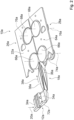
- FIG. 1 shows part of a packaging machine 50a in a schematic representation.
- the packaging machine 50a preferably comprises a horizontal forming device 10a, in particular for horizontal tubular bag machines, with at least one, in particular roll-free, forming unit 12a, in particular a forming shoulder, which is intended to form a packaging material web 14a, in particular a paper web and/or a film web, into a packaging material tube 16a to shape.
- the packaging machine 50a is designed in particular as a horizontal tubular bag machine.
- the horizontal shaping device 10a is intended to guide a packaging material 46a, in particular the packaging material tube 16a, along a horizontal transport direction 38a, in particular along a transport direction 38a that runs at least substantially perpendicular to a gravitational force direction 52a.
- the horizontal shaping device 10a is provided at least for shaping and/or guiding the packaging material web 14a, with the packaging material 46a preferably being designed as a paper and/or as a film.
- the packaging material web 14a is designed as a paper web and/or as a film web.
- the horizontal forming device 10a can be provided in addition to or at least as an alternative to forming and/or guiding a packaging material web 14a, with the packaging material 46a being designed differently from paper, for example as a plastic.
- the packaging material web 14a can alternatively be made of a plastic.
- the packaging material 46a is intended in particular for packaging, in particular for a wrapping, of products 24a, in particular food products (cf. Figure 3 ).
- the packaging material 46a is preferably designed as packaging paper.
- the packaging machine 50a comprises at least one packaging material unwinding unit 54a, which is intended to receive the packaging material 46a, in particular as a packaging material roll 56a.
- the packaging material unwinding unit 54a is intended to unwind the packaging material 46a as a packaging material web 14a, in particular to feed it to a packaging material supply unit 58a of the packaging machine 50a.
- the packaging material supply unit 58a is intended in particular to supply the packaging material web 14a to the horizontal forming device 10a, in particular to the forming unit 12a.
- the packaging material supply unit 58a can comprise a plurality of components, in particular known to a person skilled in the art, such as at least one rocker arm, at least one centering button, at least one web edge control and/or at least one printing unit for printing on the packaging material 46a.
- the packaging material tube 16a is intended to envelop products 24a to be packaged.
- the packaging machine 50a has at least one product feed unit 60a, in particular a conveyor belt, a driver chain or the like, which is intended to wrap the products 24a to be packaged through the packaging material tube 16a into an area of the horizontal molding device 10a, in particular the molding unit 12a, to transport.
- the packaging machine 50a comprises at least one longitudinal sealing unit 64a, which is intended to create a longitudinal sealing seam of the packaging material tube 16a, in particular at least substantially parallel to the transport direction 38a of the packaging material tube 16a, in particular by pressure on the packaging material 46a and/or by a Heat input into the packaging material 46a.
- the longitudinal sealing unit 64a is arranged along the transport direction 38a of the packaging material tube 16a after the horizontal forming device 10a, in particular after a mold guide unit 18a of the horizontal forming device 10a (see FIG. 2).
- the longitudinal sealing unit 64a comprises at least one pair of sealing rollers 66a, 68a, in particular heatable, profiled and/or pressurizable, which are intended to transport the packaging material tube 16a, in particular by rotation (cf. Figure 2 ).
- the longitudinal sealing unit 64a preferably comprises a plurality of pairs of sealing rollers 66a, 68a, with at least a first pair of sealing rollers 66a arranged along the transport direction 38a of the packaging material tube 16a after the horizontal forming device 10a being designed to be heat-free, in particular for heating-free transport of the packaging material tube 16a.
- the packaging machine 50a preferably comprises at least one transverse sealing unit 70a, which is intended, in particular after each product 24a, to create transverse sealing seams of the packaging material tube 16a, which in particular run at least substantially perpendicular to the transport direction 38a of the packaging material tube 16a, in particular by applying pressure the packaging material 46a and/or by heat input into the packaging material 46a.
- the transverse sealing unit 70a is intended to separate the packaging material tube 16a into individual packages, each of which in particular encloses a product 24a.
- the transverse sealing unit 70a is arranged along the transport direction 38a of the packaging material tube 16a after the longitudinal sealing unit 64a.
- the molding unit 12a is preferably intended to deflect the packaging material web 14a.
- the packaging material supply unit 58a is intended to supply the packaging material web to the molding unit 12a 14a along a direction, in particular inlet direction 20a, which runs transversely, in particular at least essentially perpendicularly, to the transport direction 38a of the packaging material tube 16a.
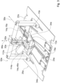
- FIG 2 shows a part of the horizontal forming device 10a of the packaging machine 50a Figure 1 in a schematic perspective view.
- the horizontal forming device 10a preferably comprises at least one, in particular the aforementioned, mold guide unit 18a, in particular a further molding shoulder, which is intended to move the packaging material tube 16a transversely to an, in particular transversely to the aforementioned, inlet direction 20a of the packaging material web 14a on the molding unit 12a while maintaining a to continue the material tension generated by the molding unit 12a, in particular homogeneous.
- the molding unit 12a preferably has at least one folding edge 72a around which the packaging material web 14a can be deflected.
- the folding edge 72a is preferably designed as a shoulder edge and the molding unit 12a as a molding shoulder.
- the molding unit 12a is designed to be free of rollers to deflect the packaging material web 14a.
- the molding unit 12a is intended to deflect the packaging material web 14a at the folding edge 72a in a direction transverse to the inlet direction 20a of the packaging material web 14a and transverse to the transport direction 38a of the packaging material tube 16a.
- the folded edge 72a extends at least substantially perpendicular to the inlet direction 20a of the packaging material web 14a and to the transport direction 38a of the packaging material tube 16a.
- the folding edge 72a and/or at least one further folding edge 110a of the molding unit 12a are intended to generate a homogeneous material tension in the packaging material 46a.
- the mold guide unit 18a is preferably intended to hold the packaging material tube 16a at least essentially perpendicular to the inlet direction 20a of the packaging material web 14a on the molding unit 12a, in particular along the transport direction 38a of the packaging material tube 16a, while maintaining the flow from the molding unit 12a, in particular from the folding edge 72a and / or to continue the homogeneous material tension generated by the further folding edge 110a.
- the mold guide unit 18a is along the Transport direction 38a of the packaging material tube 16a is arranged after the molding unit 12a and in particular in front of the longitudinal sealing unit 64a.
- the mold guide unit 18a is designed without rollers to deflect the packaging material tube 16a, in particular as a further mold shoulder.
- the mold guide unit 18a can have a geometry that is at least essentially analogous to a geometry of the mold unit 12a.
- the mold guide unit 18a is preferably designed, in particular arranged, separately from the mold unit 12a.
- the mold guide unit 18a is preferably designed as an independent component or as an independent assembly, in particular made up of two symmetrical components.
- the mold guide unit 18a is spaced apart from the packaging material tube 16a along a direction that is at least substantially perpendicular to the transport direction 38a of the packaging material tube 16a, in particular along the inlet direction 20a of the packaging material web 14a, and/or, in the present exemplary embodiment by way of example and, along the transport direction 38a of the packaging material tube 16a Molding unit 12a arranged.
- the mold guide unit 18a is designed in one piece with the mold unit 12a, in particular as a mold guide extension of the mold unit 12a.
- the horizontal forming device 10a preferably comprises at least one support surface 22a, in particular a worktop, on which products 24a to be packaged can be transported, the molding unit 12a and the mold guide unit 18a being arranged on sides 26a, 28a of the support surface 22a facing away from one another.
- the support surface 22a preferably forms a piece of track on which the products 24a can be transported.
- the support surface 22a preferably extends at least substantially parallel to the transport direction 38a of the packaging material tube 16a.
- the product feed unit 60a, the longitudinal sealing unit 64a, in particular the sealing rollers 66a, 68a, and/or the transverse sealing unit 70a are arranged at least in sections within the support surface 22a and extend/extend at least in sections through the support surface 22a.
- rotation axes 74a, 76a of the sealing rollers 66a, 68a of the longitudinal sealing unit 64a run at least substantially perpendicular to the support surface 22a.
- the molding unit is 12a is arranged on a side 26a of the support surface 22a, on which the products 24a can be transported and on which in particular the packaging material unwinding unit 54a and the packaging material supply unit 58a are arranged.
- the mold guide unit 18a is preferably arranged on a further side 28a of the support surface 22a, on which in particular the longitudinal sealing unit 64a is at least substantially parallel to the axes of rotation 74a, 76a of the sealing rollers 66a, at least to a large extent, in particular more than 50% of a maximum extent of the longitudinal sealing unit 64a , 68a, is arranged.
- the mold guide unit 18a can be coupled to the support surface 22a at least in sections.
- the packaging material tube 16a extends at least in sections through the support surface 22a, in particular onto the further side 28a of the support surface 22a.
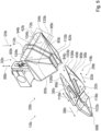
- FIG 3 shows part of the packaging machine 50a Figure 1 in a schematic perspective view.
- the horizontal forming device 10a preferably has at least one, in particular U-shaped, product and/or packaging material guide tunnel 78a, which is intended to support the packaging material tube 16a.
- the product and/or packaging material guide tunnel 78a is arranged in particular on the side 26a of the support surface 22a facing the molding unit 12a, in particular fastened to the support surface 22a.
- the product and/or packaging material guide tunnel 78a extends in particular along the transport direction 38a of the packaging material tube 16a from at least in front of the molding unit 12a to the molding unit 12a, preferably to the molding guide unit 18a and particularly preferably to the first pair of sealing rollers 66a of the longitudinal sealing unit 64a.
- the product and/or packaging material guide tunnel 78a has a cross section that is at least substantially analogous to a cross section of products 24a to be packaged, in particular a slightly larger cross section than the products 24a to be packaged.
- the products 24a can be transported within the product and/or packaging material guide tunnel 78a.
- the molding unit 12a is intended to shape the packaging material tube 16a at least in sections around the product and/or packaging material guide tunnel 78a, in particular around outer edges of the product and/or packaging material guide tunnel 78a.
- the product and/or packaging material guide tunnel 78a is intended to support the packaging material tube 16a, in particular in addition to the mold guide unit 18a.
- the horizontal forming device 10a and the packaging machine 50a are designed free of the product and/or packaging material guide tunnel 78a.
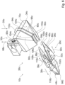
- Figure 4 shows a part of the horizontal forming device 10a of the packaging machine 50a Figure 1 in another schematic perspective view.
- the molding unit 12a preferably has at least two mold contour edges 80a, which extend from the folding edge 72a transversely to the folding edge 72a, in particular in a V-shape.
- the packaging material web 14a can be formed around the mold contour edges 80a and around the further folding edge 110a to form the packaging material tube 16a.
- the mold contour edges 80a preferably extend along a running direction of the packaging material 46a and/or along an outer contour of the supplied products 24a from the folded edge 72a to the further folded edge 110a, in particular to a mold tunnel 82a of the molding unit 12a, which is intended to hold the packaging material tube 16a along the transport direction 38a of the packaging material tube 16a.
- a longitudinal axis 84a of the mold tunnel 82a runs at least substantially parallel to the transport direction 38a of the packaging material tube 16a.
- the shape guide unit 18a comprises at least one, in particular three-dimensional, shape guide contour 86a, which is intended to support the guided packaging material tube 16a, in particular at least one outer edge of the packaging material tube 16a, in particular to achieve maintenance of the homogeneous material tension.
- the mold guide unit 18a has at least two mold guide contours 86a, which in particular are mirror-symmetrical about an imaginary plane of symmetry, which extends at least substantially parallel to the transport direction 38a of the packaging material tube 16a, in which in particular the transport direction 38a of the packaging material tube 16a runs, and which is at least in Extending essentially perpendicular to the folding edge 72a of the molding unit 12a, are arranged.
- the mold guide unit 18a is designed to be mirror-symmetrical, in particular around the imaginary plane of symmetry.
- the mold guide unit 18a and/or the mold unit 12a are/is designed asymmetrically.
- the horizontal forming device 10a preferably comprises at least one adjustment unit 30a, 32a, which is intended to adjustably mount the forming unit 12a and the forming guide unit 18a to realize different packaging material tube geometries, in particular in different adjustment planes.
- the horizontal forming device 10a preferably comprises at least two adjustment units 30a, 32a, with one adjustment unit 30a being intended to adjustably mount the forming unit 12a, and another adjustment unit 32a being intended to adjustably mount the molding guide unit 18a.
- different packaging material tube geometries may be required for packaging different products 24a.
- the packaging machine 50a is intended for packaging different products 24a, which in particular have different dimensions.
- packaging material tube geometries for packaging different products 24a which have different maximum extensions at least substantially perpendicular to the support surface 22a, in particular different heights, and/or the different maximum extensions at least substantially parallel to the support surface 22a and at least substantially perpendicular to the Transport direction 38a of the packaging material tube 16a, in particular different widths, are required.
- a maximum extension of the packaging material tube 16a is/is at least essentially perpendicular to the support surface 22a, in particular a height of the packaging material tube 16a, and/or a maximum extent of the packaging material tube 16a is at least essentially parallel to the support surface 22a and at least essentially perpendicular to the transport direction 38a of the packaging material tube 16a, in particular a width of the packaging material tube 16a, adjustable.
- the shape guide unit 18a can be adjustable by means of the further adjustment unit 32a to correct uneven tension conditions in the packaging material 46a.
- the molding unit 12a is adjustable in at least one adjustment plane extending on the side 26a of the support surface 22a facing the molding unit 12a.
- the mold guide unit 18a is adjustable in at least one further adjustment plane extending on the further side 28a of the support surface 22a facing the mold guide unit 18a.
- the mold unit 12a and/or the mold guide unit 18a are/are mounted adjustably as a whole component or as a whole assembly.
- the mold unit 12a and/or the mold guide unit 18a are adjustable in themselves, in particular individual components of the mold unit 12a relative to one another and/or individual components of the mold guide unit 18a relative to one another.
- the at least one setting unit 30a, 32a in particular the setting units 30a, 32a, is/are intended to mount the mold unit 12a and the mold guide unit 18a so that they can be adjusted relative to one another.
- the setting units 30a, 32a are intended to mount the mold unit 12a and the mold guide unit 18a as a whole component or as a whole assembly so that they can be adjusted relative to one another.
- the setting units 30a, 32a are preferably intended to mount the mold unit 12a and the mold guide unit 18a in a linearly movable and/or pivoting manner.
- the adjustment unit 30a is intended to support the molding unit 12a, in particular for adjusting a height of the packaging material tube 16a, in an at least linearly movable manner along an adjustment direction 88a that runs at least substantially perpendicular to the support surface 22a.
- the adjustment unit 30a comprises at least one linear guide 90a, which is intended to support the molding unit 12a in a linearly movable manner along the adjustment direction 88a.
- the adjustment unit 30a comprises at least one further linear guide 112a, which is intended to support the molding unit 12a in a linearly movable manner along a further adjustment direction 114a which runs at least essentially perpendicular to the adjustment direction 88a and at least essentially parallel to the transport direction 38a of the packaging material tube 16a (cf . Figure 3 ).
- the further adjustment unit 32a is intended to move the mold guide unit 18a at least linearly along at least one at least substantially parallel to the support surface 22a, in particular transverse to the transport direction 38a of the packaging material tube 16a, extending adjustment direction 92a, 116a.
- the setting units 30a, 32a are preferably designed as manual setting units for manual adjustment of the mold unit 12a and the mold guide unit 18a, in particular relative to one another.
- at least one of the adjustment units 30a, 32a has at least one automatic adjustment element, in particular a servomotor, which is provided for automatic adjustment of the mold unit 12a and/or the mold guide unit 18a.
- the at least one adjustment unit 30a, 32a in particular the adjustment units 30a, 32a, is/are intended to mount at least two mold legs 34a, 36a of the mold unit 12a and/or the mold guide unit 18a so that they can be adjusted relative to one another.
- the mold unit 12a has at least two mold legs 34a, which are mounted so that they can be adjusted relative to one another, in particular so that they can be moved linearly and/or pivotally.
- the mold legs 34a of the molding unit 12a are mounted so that they are at least linearly movable relative to one another, in particular along a direction that is at least substantially parallel to the folded edge 72a, in particular to a folded edge running surface.
- the adjustment unit 30a comprises at least one transverse bearing element 94a, which is intended to support the mold legs 34a of the mold unit 12a so that they can move at least linearly relative to one another.
- the mold legs 34a of the molding unit 12a jointly form the folded edge 72a, in particular the folded edge running surface.
- the mold legs 34a of the molding unit 12a are mounted to be movable toward and away from one another, in particular along the direction that runs at least substantially parallel to the folded edge 72a, in particular to adjust a width of the packaging material tube 16a.
- the mold legs 34a of the molding unit 12a together form the molding tunnel 82a of the molding unit 12a.
- each mold leg 34a of the molding unit 12a forms at least one mold contour edge 80a of the molding unit 12a.
- the adjustment unit 30a preferably has at least one intermediate element 96a, in particular a plurality of intermediate elements 96a, to fill a space between the two mold legs 34a of the mold unit 12a that move away from one another, in particular to ensure different product widths.
- the mold guide unit 18a has at least two mold legs 36a, which are mounted so that they can be adjusted relative to one another, in particular so that they can be moved linearly and/or pivotally.
- the further adjustment unit 32a which is provided for adjustable mounting of the mold guide unit 18a, can be designed in an alternative embodiment at least essentially analogous to the adjustment unit 30a, which is provided for adjustable storage of the mold unit 12a.
- the mold legs 36a of the mold guide unit 18a are mounted so that they can move at least linearly relative to one another.
- the further adjustment unit 32a is intended to mount the mold legs 36a of the mold guide unit 18a in a linearly movable manner along different, in particular transverse, adjustment directions 92a, 116a, in particular to ensure different product widths.
- the adjustment directions 92a, 116a run in a common plane, in particular extending at least substantially parallel to the support surface 22a, and in particular include equal angles with the transport direction 38a of the packaging material tube 16a.
- the mold legs 36a of the mold guide unit 18a can be mounted so that they can be at least pivotally movable relative to one another, in particular in a pivot plane that extends at least substantially parallel to the support surface 22a, in particular to adjust the width of the packaging material tube 16a.
- the mold legs 36a of the mold guide unit 18a can be pivotally mounted on an end region 98a of the mold legs 36a of the mold guide unit 18a that is remote from the mold unit 12a along the transport direction 38a of the packaging material tube 16a.
- the end region 98a of the mold legs 36a of the mold guide unit 18a can be formed, in particular mounted, separately from a remaining region of the mold guide unit 18a, in particular separated from the remaining region along a separating cut 118a.
- each mold leg 36a of the mold guide unit 18a forms at least one mold guide contour 86a of the mold guide unit 18a.
- the mold legs 36a of the mold guide unit 18a are arranged, in particular mounted, in mirror symmetry to one another around the imaginary plane of symmetry.
- the mold legs 36a of the mold guide unit 18a preferably form a V-shaped tapering guide region 40a in the transport direction 38a of the packaging material tube 16a, which is intended to bring together seam regions of the packaging material tube 16a that are to be sealed with one another.
- the guide area 40a is intended to bring together longitudinal sealing seam areas of the packaging material tube 16a that are to be sealed with one another.
- the mold legs 36a of the mold guide unit 18a in an end region 100a facing the mold unit 12a have a greater distance from one another along a direction that is at least substantially parallel to the support surface 22a and at least substantially perpendicular to the transport direction 38a of the packaging material tube 16a than in that of the mold unit 12a facing away from the end region 98a.
- the seam areas of the packaging material tube 16a are in particular areas in which the packaging material 46a, in particular the packaging paper, is sealed, in particular to create a sealing seam.
- the guide area 40a is intended to bring the seam areas together in such a way that the seam areas can be transported between two sealing rollers 66a, 68a of the pairs of sealing rollers 66a, 68a to form a seal.
- the guide region 40a preferably opens in the end region 98a facing away from the mold unit 12a into a support contour 102a formed by the mold legs 36a of the mold guide unit 18a, which is intended to support the packaging material tube 16a, in particular the joined seam regions, in particular during further transport to the longitudinal sealing unit 64a.
- FIG. 5 shows part of a first alternative horizontal forming device 10b in a schematic perspective view.
- the horizontal forming device 10b in particular comprises at least one forming unit 12b and at least one forming guide unit 18b.
- the horizontal shaping device 10b preferably comprises at least one heating unit 42b, which is intended to heat the shaping unit 12b and/or the shape guiding unit 18b at least in sections, in particular to introduce heat into a seam area, in particular a packaging material.
- the heating unit 42b is intended to enable a prior heat input into the packaging material, in particular into the packaging paper, during a sealing, in particular a longitudinal sealing, of the packaging material, in particular a packaging paper.
- the heating unit 42b is intended to seal the packaging material, in particular the packaging paper, in particular on the form guide unit 18b, in particular as an alternative to sealing by a longitudinal sealing unit of a packaging machine, and/or to ensure increased heat input, in particular in an area of a support contour 102b of the mold guide unit 18b.
- the heating unit 42b can in particular be designed as a heating coil, as a heating cartridge, as a heating plate, as a thick-film heating element or as another heating unit that appears sensible to a person skilled in the art.
- the heating unit 42b is preferably arranged on the mold unit 12b and/or on the mold guide unit 18b, and is in particular in direct contact with the mold unit 12b and/or the mold guide unit 18b.
- the horizontal molding device 10b can have a plurality of heating units 42b, wherein at least one heating unit 42b can be assigned to the molding unit 12b and at least one further heating unit 42b can be assigned to the mold guide unit 18b.
- the heating unit 42b is arranged on a side of the mold unit 12b and/or the mold guide unit 18b facing away from a contact surface 104b with the packaging material, in particular with the packaging paper.
- the horizontal forming device 10b has, for example, a single heating unit 42b, which is located on the forming unit 12b, in particular on the contact surface 104b facing away from the packaging material Side of the molding unit 12b, is arranged, in particular in direct contact with the molding unit 12b.
- a heater which is arranged parallel to a surface 120b of the molding unit 12b, in particular at a distance from the molding unit 12b, is conceivable, which heats the packaging material on an inside.
- the molding unit 12b and/or the molding guide unit 18b are intended to transfer thermal energy absorbed by the heating unit 42b to the packaging material, in particular to the packaging paper.
- the mold unit 12b, in particular the mold legs 34b of the mold unit 12b, and/or the mold guide unit 18b, in particular the mold legs 36b of the mold guide unit 18b, in the present exemplary embodiment by way of example at least the mold unit 12b are made of a thermally conductive material, in particular made of a metal, educated.
- the molding unit 12b and/or the molding guide unit 18b, in the present exemplary embodiment for example the molding unit 12b, on the contact surface 104b with the packaging material, in particular with the packaging paper, is/is intended to transfer thermal energy provided by the heating unit 42b to the packaging material, in particular in the seam areas.
- at least one sealing layer of the packaging paper can be activated by applying heat to the seam areas.
- FIG. 6 shows part of a second alternative horizontal forming device 10c in a schematic perspective view.
- the horizontal molding device 10c in particular includes at least one molding unit 12c and at least one molding guide unit 18c.
- the horizontal molding device 10c preferably comprises at least one air pressure unit 44c, which is intended to exert a negative pressure and/or an excess pressure on a packaging material at the molding unit 12c and/or at the mold guide unit 18c.
- the horizontal forming device 10c has, for example, two air pressure units 44c, with one of the air pressure units 44c being intended to exert a negative pressure and/or an excess pressure on the packaging material on a mold leg 36c of the mold guide unit 18c.
- the air pressure units 44c can in particular be used as blowers, as vacuum cleaners or be designed as other air pressure units that appear useful to a person skilled in the art.
- the horizontal molding device 10c can have a plurality of air pressure units 44c, wherein at least one air pressure unit 44c can be assigned to the molding unit 12c and at least one further air pressure unit 44c can be assigned to the mold guide unit 18c.
- the air pressure units 44c are arranged on a side of the molding unit 12c and/or the molding guide unit 18c, in the present exemplary embodiment for example the molding guide unit 18c, facing away from a contact surface 106c with the packaging material, in particular with a packaging paper.
- the mold unit 12c, in particular mold legs 34c of the mold unit 12c, and/or the mold guide unit 18c, in particular the mold legs 36c of the mold guide unit 18c, in the present exemplary embodiment for example the mold guide unit 18c are formed at least in sections perforated, in particular made of a porous material.
- the mold legs 36c of the mold guide unit 18c have a perforation 108c.
- air from an air flow generated by the air pressure units 44c can flow at least in sections through the mold unit 12c and/or the mold guide unit 18c, in the present exemplary embodiment for example through the mold guide unit 18c.
- the air pressure units 44c are provided to generate a negative pressure for suction of the packaging paper to the molding unit 12c and/or to the molding guide unit 18c, in the present exemplary embodiment, for example, to the molding guide unit 18c, in particular to achieve a low-crease contact of the packaging paper on the Mold unit 12c and/or on the mold guide unit 18c, in the present exemplary embodiment for example on the mold guide unit 18c.
- the air pressure units 44c are intended to generate an overpressure to form an air cushion on the molding unit 12c and/or on the molding guide unit 18c, in the present exemplary embodiment for example on the molding guide unit 18c, in particular to realize a low-friction transport of the packaging paper along the Mold unit 12c and/or along the mold guide unit 18c, in the present exemplary embodiment, for example, along the mold guide unit 18c.
- the air pressure units 44c can be switched between generating a negative pressure and generating an overpressure, in particular depending on an application situation, for example depending on the packaging material used.
- FIG. 7 shows part of a third alternative horizontal forming device 10d in a schematic perspective view.
- the horizontal forming device 10d comprises at least one forming unit 12d and at least one forming guide unit 18d.
- the horizontal forming device 10d preferably comprises at least one driven pressure unit 48d, in particular a pressure roller, which is intended to apply a pressure force to a packaging material against the mold guide unit 18d.
- the horizontal forming device 10d preferably comprises the at least one driven pressure unit 48d as an alternative or in addition, in the present exemplary embodiment as an alternative, to an air pressure unit assigned to the mold guiding unit 18d.
- the horizontal forming device 10d preferably comprises at least two driven pressure units 48d, with at least one driven pressure unit 48d being assigned to a mold leg 36d of the mold guide unit 18d, in particular being intended to apply a pressure force to the packaging material against the mold leg 36d.
- the horizontal forming device 10d includes at least one additional driven pressure unit 48d, in particular an additional pressure roller, which is intended to apply a pressure force to the packaging material against the molding unit 12d.
- the driven pressure units 48d are preferably designed as pressure rollers which can be driven to perform rotational movements, in particular to transport a packaging material tube along a transport direction 38d of the packaging material tube.
- the driven pressure units 48d are intended to guide the packaging material tube between the driven pressure units 48d and the mold guide unit 18d, in particular the mold legs 36d of the mold guide unit 18d.
Landscapes
- Engineering & Computer Science (AREA)
- Mechanical Engineering (AREA)
- Containers And Plastic Fillers For Packaging (AREA)
- Package Closures (AREA)
- Folding Of Thin Sheet-Like Materials, Special Discharging Devices, And Others (AREA)
Applications Claiming Priority (2)
| Application Number | Priority Date | Filing Date | Title |
|---|---|---|---|
| DE102019132878.0A DE102019132878A1 (de) | 2019-12-03 | 2019-12-03 | Horizontalformvorrichtung |
| PCT/EP2020/083974 WO2021110604A1 (de) | 2019-12-03 | 2020-11-30 | Horizontalformvorrichtung |
Publications (2)
| Publication Number | Publication Date |
|---|---|
| EP4069593A1 EP4069593A1 (de) | 2022-10-12 |
| EP4069593B1 true EP4069593B1 (de) | 2023-09-27 |
Family
ID=73654829
Family Applications (1)
| Application Number | Title | Priority Date | Filing Date |
|---|---|---|---|
| EP20816976.3A Active EP4069593B1 (de) | 2019-12-03 | 2020-11-30 | Horizontalformvorrichtung |
Country Status (7)
| Country | Link |
|---|---|
| US (1) | US12319526B2 (da) |
| EP (1) | EP4069593B1 (da) |
| JP (1) | JP7397198B2 (da) |
| CN (1) | CN114746339B (da) |
| DE (1) | DE102019132878A1 (da) |
| DK (1) | DK4069593T3 (da) |
| WO (1) | WO2021110604A1 (da) |
Families Citing this family (5)
| Publication number | Priority date | Publication date | Assignee | Title |
|---|---|---|---|---|
| DE102020101759A1 (de) | 2020-01-24 | 2021-07-29 | Syntegon Packaging Systems Ag | Erstverpackung zu einer Aufnahme zumindest eines Produkts, insbesondere eines Lebensmittels |
| IT202000014857A1 (it) * | 2020-06-22 | 2021-12-22 | Ilapak Int S A | Gruppo piegatore per la piegatura di un materiale in film a formare un involucro tubolare. |
| IT202100026198A1 (it) * | 2021-10-13 | 2023-04-13 | Ilapak Int S A | Apparecchiatura confezionatrice orizzontale. |
| DE102022118077A1 (de) | 2022-07-19 | 2024-01-25 | Syntegon Packaging Systems Ag | Verpackungsformvorrichtung sowie Verpackungsmaschine |
| DE102023118754A1 (de) | 2023-07-14 | 2025-01-16 | Syntegon Packaging Systems Ag | Horizontalformvorrichtung, Verpackungsmaschine mit einer derartigen Horizontalformvorrichtung sowie Stützeinheit für eine derartige Horizontalformvorrichtung |
Family Cites Families (22)
| Publication number | Priority date | Publication date | Assignee | Title |
|---|---|---|---|---|
| DE1586334B1 (de) * | 1967-10-19 | 1972-03-16 | Nagema Veb K | Faltvorrichtung zum Umformen einer ebenen Folienbahn in einen Huellschlauch |
| JPS5633705Y2 (da) | 1977-03-25 | 1981-08-10 | ||
| JPS577601Y2 (da) | 1977-09-12 | 1982-02-13 | ||
| JPS55143494U (da) | 1979-03-31 | 1980-10-14 | ||
| JPS5767903U (da) * | 1980-10-07 | 1982-04-23 | ||
| US4520615A (en) * | 1983-02-28 | 1985-06-04 | Doboy Packaging Machinery, Inc. | Tube forming apparatus for packaging |
| JP2597441B2 (ja) * | 1992-03-31 | 1997-04-09 | 株式会社ハナガタ | 半折りフィルム等の合成樹脂包装材料による連続包装機 |
| US5255495A (en) * | 1992-10-30 | 1993-10-26 | Hayssen Manufacturing Company | Adjustable girth former |
| JP2567556B2 (ja) * | 1993-04-27 | 1996-12-25 | 株式会社ハナガタ | 帯状包装材料による連続包装機 |
| JP2854251B2 (ja) | 1994-10-25 | 1999-02-03 | 株式会社フジキカイ | 横型製袋充填包装機におけるフイルム製袋装置 |
| DE19618559A1 (de) * | 1996-05-09 | 1997-11-13 | Kallfass Gmbh | Verpackungsmaschine |
| JP3002771B2 (ja) * | 1996-06-25 | 2000-01-24 | 株式会社フジキカイ | 横型製袋充填機のフィルム製袋装置 |
| JP3713108B2 (ja) * | 1996-08-14 | 2005-11-02 | 富士写真フイルム株式会社 | ピロータイプ包装装置 |
| FR2820361B1 (fr) | 2001-02-02 | 2003-07-25 | Flexico France Sarl | Procede de fabrication de sachets a profiles de fermeture complementaires, machine et sachets obtenus |
| US6745545B2 (en) * | 2001-06-20 | 2004-06-08 | Illinois Tool Works Inc. | Horizontal form, fill and seal machine for loose fitting packages |
| JP2004035084A (ja) | 2002-07-05 | 2004-02-05 | Fuji Photo Film Co Ltd | 包装袋のシーリング方法及びシーリング機構 |
| JP2005228871A (ja) | 2004-02-12 | 2005-08-25 | Seiko Epson Corp | 実装構造体、電気光学装置及び電子機器 |
| CN101177171B (zh) * | 2007-08-22 | 2010-04-21 | 张建军 | 袋中袋全自动成型包装机 |
| CH699875A1 (de) * | 2008-11-13 | 2010-05-14 | Ferag Ag | Vorrichtung und verfahren zur bildung eines schlauchs aus einer materialbahn. |
| CN104309842B (zh) | 2014-09-03 | 2016-06-15 | 成都松川雷博机械设备有限公司 | 一种适用于物料包装机的半成品成型方法 |
| CN105857668B (zh) | 2016-06-01 | 2018-03-20 | 倪舒婷 | 一种枕形袋的成型结构及其枕形袋的成型工艺 |
| CN109353596A (zh) | 2018-11-01 | 2019-02-19 | 青岛海科佳电子设备制造有限公司 | 宽度可调包装袋成型器、制袋器、包装机及方法 |
-
2019
- 2019-12-03 DE DE102019132878.0A patent/DE102019132878A1/de not_active Withdrawn
-
2020
- 2020-11-30 CN CN202080083281.5A patent/CN114746339B/zh active Active
- 2020-11-30 WO PCT/EP2020/083974 patent/WO2021110604A1/de not_active Ceased
- 2020-11-30 DK DK20816976.3T patent/DK4069593T3/da active
- 2020-11-30 JP JP2022533353A patent/JP7397198B2/ja active Active
- 2020-11-30 EP EP20816976.3A patent/EP4069593B1/de active Active
- 2020-11-30 US US17/781,807 patent/US12319526B2/en active Active
Also Published As
| Publication number | Publication date |
|---|---|
| BR112022010164A2 (pt) | 2022-08-09 |
| CN114746339B (zh) | 2023-10-27 |
| JP7397198B2 (ja) | 2023-12-12 |
| JP2023509298A (ja) | 2023-03-08 |
| DE102019132878A1 (de) | 2021-06-10 |
| WO2021110604A1 (de) | 2021-06-10 |
| CN114746339A (zh) | 2022-07-12 |
| US20230174332A1 (en) | 2023-06-08 |
| EP4069593A1 (de) | 2022-10-12 |
| US12319526B2 (en) | 2025-06-03 |
| DK4069593T3 (da) | 2023-12-18 |
Similar Documents
| Publication | Publication Date | Title |
|---|---|---|
| EP4069593B1 (de) | Horizontalformvorrichtung | |
| DE69117095T2 (de) | Strömungsmittelbetätigte Vorrichtung und Verfahren zur Stabilisierung | |
| EP4143095B1 (de) | Horizontalformvorrichtung | |
| EP0899228B1 (de) | Luftpolsterführung | |
| DE3327462A1 (de) | Verfahren und vorrichtung zum abdecken der offenen schnittkante eines kartonzuschnittes | |
| WO2018059730A1 (de) | Verfahren und vorrichtung zum zuführen von wäschestücken zu einer wäschebehandlungseinrichtung, insbesondere einer mangel | |
| EP0240827A1 (de) | Vorrichtung zur Herstellung von Luftpolster-Versandtaschen | |
| EP0285855A1 (de) | Verfahren und Vorrichtung zum Verpacken von Gegenständen mit einer bahnförmigen Kunststoffolie | |
| EP3070009A1 (de) | Vorrichtung und verfahren zur herstellung von folienschrumpfgebinden | |
| EP1868932A1 (de) | Verfahren und vorrichtung zum ablegen einer flexiblen materialbahn | |
| EP3269539B1 (de) | Vorrichtung zum öffnen eines endbereichs eines schlauchförmigen sackkörpers | |
| EP2711164B1 (de) | Vorrichtung und Verfahren zum Öffnen eines Endbereichs eines schlauchförmigen Sackkörpers | |
| EP0806346A2 (de) | Mit einer Schlauchformeinrichtung versehene Verpackungsmaschine | |
| DE2212936A1 (de) | Vorrichtung zum ausrichten einer packstoffbahn innerhalb einer schlauchbeutelmaschine | |
| DE102008017443B4 (de) | Vorrichtung und Verfahren zur Herstellung von Säcken aus Schlauchstücken | |
| DE102013014732B4 (de) | Verfahren und Vorrichtung zur Herstellung von Kreuzboden-Säcken | |
| DE69500781T2 (de) | Luftleitflügel für eine pneumatische Wendestange | |
| DE19515718A1 (de) | Vorrichtung zum Verpacken von Gegenständen in einen Schlauchbeutel | |
| DE1461916A1 (de) | Maschine zum Herstellen,Fuellen und Verschliessen von Packungen | |
| DE69702108T2 (de) | Verfahren und Apparat zur kontaktlosen Verzögerung von flachen Produkten | |
| DE10134255B4 (de) | Verpackungsmaschine | |
| DE2420970A1 (de) | Verfahren zur herstellung von beuteln und vorrichtung zur durchfuehrung des verfahrens | |
| DE2510515C3 (de) | Vorrichtung zum Einlegen einer Tieffalte in einen Blasfolienschlauch | |
| DE102023118754A1 (de) | Horizontalformvorrichtung, Verpackungsmaschine mit einer derartigen Horizontalformvorrichtung sowie Stützeinheit für eine derartige Horizontalformvorrichtung | |
| DE1561409B1 (de) | Vorrichtung zum Herstellen von Klebefaltschachteln |
Legal Events
| Date | Code | Title | Description |
|---|---|---|---|
| STAA | Information on the status of an ep patent application or granted ep patent |
Free format text: STATUS: UNKNOWN |
|
| STAA | Information on the status of an ep patent application or granted ep patent |
Free format text: STATUS: THE INTERNATIONAL PUBLICATION HAS BEEN MADE |
|
| PUAI | Public reference made under article 153(3) epc to a published international application that has entered the european phase |
Free format text: ORIGINAL CODE: 0009012 |
|
| STAA | Information on the status of an ep patent application or granted ep patent |
Free format text: STATUS: REQUEST FOR EXAMINATION WAS MADE |
|
| 17P | Request for examination filed |
Effective date: 20220629 |
|
| AK | Designated contracting states |
Kind code of ref document: A1 Designated state(s): AL AT BE BG CH CY CZ DE DK EE ES FI FR GB GR HR HU IE IS IT LI LT LU LV MC MK MT NL NO PL PT RO RS SE SI SK SM TR |
|
| DAV | Request for validation of the european patent (deleted) | ||
| DAX | Request for extension of the european patent (deleted) | ||
| GRAP | Despatch of communication of intention to grant a patent |
Free format text: ORIGINAL CODE: EPIDOSNIGR1 |
|
| STAA | Information on the status of an ep patent application or granted ep patent |
Free format text: STATUS: GRANT OF PATENT IS INTENDED |
|
| INTG | Intention to grant announced |
Effective date: 20230419 |
|
| GRAS | Grant fee paid |
Free format text: ORIGINAL CODE: EPIDOSNIGR3 |
|
| GRAA | (expected) grant |
Free format text: ORIGINAL CODE: 0009210 |
|
| STAA | Information on the status of an ep patent application or granted ep patent |
Free format text: STATUS: THE PATENT HAS BEEN GRANTED |
|
| AK | Designated contracting states |
Kind code of ref document: B1 Designated state(s): AL AT BE BG CH CY CZ DE DK EE ES FI FR GB GR HR HU IE IS IT LI LT LU LV MC MK MT NL NO PL PT RO RS SE SI SK SM TR |
|
| REG | Reference to a national code |
Ref country code: GB Ref legal event code: FG4D Free format text: NOT ENGLISH |
|
| REG | Reference to a national code |
Ref country code: CH Ref legal event code: EP |
|
| REG | Reference to a national code |
Ref country code: DE Ref legal event code: R096 Ref document number: 502020005451 Country of ref document: DE |
|
| REG | Reference to a national code |
Ref country code: IE Ref legal event code: FG4D Free format text: LANGUAGE OF EP DOCUMENT: GERMAN |
|
| REG | Reference to a national code |
Ref country code: DK Ref legal event code: T3 Effective date: 20231214 |
|
| REG | Reference to a national code |
Ref country code: NL Ref legal event code: FP |
|
| REG | Reference to a national code |
Ref country code: LT Ref legal event code: MG9D |
|
| PG25 | Lapsed in a contracting state [announced via postgrant information from national office to epo] |
Ref country code: GR Free format text: LAPSE BECAUSE OF FAILURE TO SUBMIT A TRANSLATION OF THE DESCRIPTION OR TO PAY THE FEE WITHIN THE PRESCRIBED TIME-LIMIT Effective date: 20231228 |
|
| PG25 | Lapsed in a contracting state [announced via postgrant information from national office to epo] |
Ref country code: SE Free format text: LAPSE BECAUSE OF FAILURE TO SUBMIT A TRANSLATION OF THE DESCRIPTION OR TO PAY THE FEE WITHIN THE PRESCRIBED TIME-LIMIT Effective date: 20230927 Ref country code: RS Free format text: LAPSE BECAUSE OF FAILURE TO SUBMIT A TRANSLATION OF THE DESCRIPTION OR TO PAY THE FEE WITHIN THE PRESCRIBED TIME-LIMIT Effective date: 20230927 Ref country code: NO Free format text: LAPSE BECAUSE OF FAILURE TO SUBMIT A TRANSLATION OF THE DESCRIPTION OR TO PAY THE FEE WITHIN THE PRESCRIBED TIME-LIMIT Effective date: 20231227 Ref country code: LV Free format text: LAPSE BECAUSE OF FAILURE TO SUBMIT A TRANSLATION OF THE DESCRIPTION OR TO PAY THE FEE WITHIN THE PRESCRIBED TIME-LIMIT Effective date: 20230927 Ref country code: LT Free format text: LAPSE BECAUSE OF FAILURE TO SUBMIT A TRANSLATION OF THE DESCRIPTION OR TO PAY THE FEE WITHIN THE PRESCRIBED TIME-LIMIT Effective date: 20230927 Ref country code: HR Free format text: LAPSE BECAUSE OF FAILURE TO SUBMIT A TRANSLATION OF THE DESCRIPTION OR TO PAY THE FEE WITHIN THE PRESCRIBED TIME-LIMIT Effective date: 20230927 Ref country code: GR Free format text: LAPSE BECAUSE OF FAILURE TO SUBMIT A TRANSLATION OF THE DESCRIPTION OR TO PAY THE FEE WITHIN THE PRESCRIBED TIME-LIMIT Effective date: 20231228 Ref country code: FI Free format text: LAPSE BECAUSE OF FAILURE TO SUBMIT A TRANSLATION OF THE DESCRIPTION OR TO PAY THE FEE WITHIN THE PRESCRIBED TIME-LIMIT Effective date: 20230927 |
|
| PG25 | Lapsed in a contracting state [announced via postgrant information from national office to epo] |
Ref country code: IS Free format text: LAPSE BECAUSE OF FAILURE TO SUBMIT A TRANSLATION OF THE DESCRIPTION OR TO PAY THE FEE WITHIN THE PRESCRIBED TIME-LIMIT Effective date: 20240127 |
|
| PG25 | Lapsed in a contracting state [announced via postgrant information from national office to epo] |
Ref country code: ES Free format text: LAPSE BECAUSE OF FAILURE TO SUBMIT A TRANSLATION OF THE DESCRIPTION OR TO PAY THE FEE WITHIN THE PRESCRIBED TIME-LIMIT Effective date: 20230927 |
|
| PG25 | Lapsed in a contracting state [announced via postgrant information from national office to epo] |
Ref country code: SM Free format text: LAPSE BECAUSE OF FAILURE TO SUBMIT A TRANSLATION OF THE DESCRIPTION OR TO PAY THE FEE WITHIN THE PRESCRIBED TIME-LIMIT Effective date: 20230927 Ref country code: RO Free format text: LAPSE BECAUSE OF FAILURE TO SUBMIT A TRANSLATION OF THE DESCRIPTION OR TO PAY THE FEE WITHIN THE PRESCRIBED TIME-LIMIT Effective date: 20230927 Ref country code: IT Free format text: LAPSE BECAUSE OF NON-PAYMENT OF DUE FEES Effective date: 20231130 Ref country code: IS Free format text: LAPSE BECAUSE OF FAILURE TO SUBMIT A TRANSLATION OF THE DESCRIPTION OR TO PAY THE FEE WITHIN THE PRESCRIBED TIME-LIMIT Effective date: 20240127 Ref country code: ES Free format text: LAPSE BECAUSE OF FAILURE TO SUBMIT A TRANSLATION OF THE DESCRIPTION OR TO PAY THE FEE WITHIN THE PRESCRIBED TIME-LIMIT Effective date: 20230927 Ref country code: EE Free format text: LAPSE BECAUSE OF FAILURE TO SUBMIT A TRANSLATION OF THE DESCRIPTION OR TO PAY THE FEE WITHIN THE PRESCRIBED TIME-LIMIT Effective date: 20230927 Ref country code: CZ Free format text: LAPSE BECAUSE OF FAILURE TO SUBMIT A TRANSLATION OF THE DESCRIPTION OR TO PAY THE FEE WITHIN THE PRESCRIBED TIME-LIMIT Effective date: 20230927 Ref country code: SK Free format text: LAPSE BECAUSE OF FAILURE TO SUBMIT A TRANSLATION OF THE DESCRIPTION OR TO PAY THE FEE WITHIN THE PRESCRIBED TIME-LIMIT Effective date: 20230927 Ref country code: PT Free format text: LAPSE BECAUSE OF FAILURE TO SUBMIT A TRANSLATION OF THE DESCRIPTION OR TO PAY THE FEE WITHIN THE PRESCRIBED TIME-LIMIT Effective date: 20240129 |
|
| PG25 | Lapsed in a contracting state [announced via postgrant information from national office to epo] |
Ref country code: PL Free format text: LAPSE BECAUSE OF FAILURE TO SUBMIT A TRANSLATION OF THE DESCRIPTION OR TO PAY THE FEE WITHIN THE PRESCRIBED TIME-LIMIT Effective date: 20230927 |
|
| REG | Reference to a national code |
Ref country code: DE Ref legal event code: R097 Ref document number: 502020005451 Country of ref document: DE |
|
| PG25 | Lapsed in a contracting state [announced via postgrant information from national office to epo] |
Ref country code: MC Free format text: LAPSE BECAUSE OF FAILURE TO SUBMIT A TRANSLATION OF THE DESCRIPTION OR TO PAY THE FEE WITHIN THE PRESCRIBED TIME-LIMIT Effective date: 20230927 |
|
| PG25 | Lapsed in a contracting state [announced via postgrant information from national office to epo] |
Ref country code: LU Free format text: LAPSE BECAUSE OF NON-PAYMENT OF DUE FEES Effective date: 20231130 |
|
| PG25 | Lapsed in a contracting state [announced via postgrant information from national office to epo] |
Ref country code: MC Free format text: LAPSE BECAUSE OF FAILURE TO SUBMIT A TRANSLATION OF THE DESCRIPTION OR TO PAY THE FEE WITHIN THE PRESCRIBED TIME-LIMIT Effective date: 20230927 Ref country code: LU Free format text: LAPSE BECAUSE OF NON-PAYMENT OF DUE FEES Effective date: 20231130 |
|
| REG | Reference to a national code |
Ref country code: BE Ref legal event code: MM Effective date: 20231130 |
|
| PLBE | No opposition filed within time limit |
Free format text: ORIGINAL CODE: 0009261 |
|
| STAA | Information on the status of an ep patent application or granted ep patent |
Free format text: STATUS: NO OPPOSITION FILED WITHIN TIME LIMIT |
|
| 26N | No opposition filed |
Effective date: 20240628 |
|
| REG | Reference to a national code |
Ref country code: IE Ref legal event code: MM4A |
|
| PG25 | Lapsed in a contracting state [announced via postgrant information from national office to epo] |
Ref country code: IE Free format text: LAPSE BECAUSE OF NON-PAYMENT OF DUE FEES Effective date: 20231130 |
|
| PG25 | Lapsed in a contracting state [announced via postgrant information from national office to epo] |
Ref country code: BE Free format text: LAPSE BECAUSE OF NON-PAYMENT OF DUE FEES Effective date: 20231130 |
|
| PG25 | Lapsed in a contracting state [announced via postgrant information from national office to epo] |
Ref country code: FR Free format text: LAPSE BECAUSE OF NON-PAYMENT OF DUE FEES Effective date: 20231130 |
|
| PG25 | Lapsed in a contracting state [announced via postgrant information from national office to epo] |
Ref country code: SI Free format text: LAPSE BECAUSE OF FAILURE TO SUBMIT A TRANSLATION OF THE DESCRIPTION OR TO PAY THE FEE WITHIN THE PRESCRIBED TIME-LIMIT Effective date: 20230927 |
|
| PG25 | Lapsed in a contracting state [announced via postgrant information from national office to epo] |
Ref country code: SI Free format text: LAPSE BECAUSE OF FAILURE TO SUBMIT A TRANSLATION OF THE DESCRIPTION OR TO PAY THE FEE WITHIN THE PRESCRIBED TIME-LIMIT Effective date: 20230927 Ref country code: IE Free format text: LAPSE BECAUSE OF NON-PAYMENT OF DUE FEES Effective date: 20231130 Ref country code: FR Free format text: LAPSE BECAUSE OF NON-PAYMENT OF DUE FEES Effective date: 20231130 Ref country code: BE Free format text: LAPSE BECAUSE OF NON-PAYMENT OF DUE FEES Effective date: 20231130 |
|
| PG25 | Lapsed in a contracting state [announced via postgrant information from national office to epo] |
Ref country code: BG Free format text: LAPSE BECAUSE OF FAILURE TO SUBMIT A TRANSLATION OF THE DESCRIPTION OR TO PAY THE FEE WITHIN THE PRESCRIBED TIME-LIMIT Effective date: 20230927 |
|
| PG25 | Lapsed in a contracting state [announced via postgrant information from national office to epo] |
Ref country code: BG Free format text: LAPSE BECAUSE OF FAILURE TO SUBMIT A TRANSLATION OF THE DESCRIPTION OR TO PAY THE FEE WITHIN THE PRESCRIBED TIME-LIMIT Effective date: 20230927 |
|
| PG25 | Lapsed in a contracting state [announced via postgrant information from national office to epo] |
Ref country code: CY Free format text: LAPSE BECAUSE OF FAILURE TO SUBMIT A TRANSLATION OF THE DESCRIPTION OR TO PAY THE FEE WITHIN THE PRESCRIBED TIME-LIMIT; INVALID AB INITIO Effective date: 20201130 |
|
| PG25 | Lapsed in a contracting state [announced via postgrant information from national office to epo] |
Ref country code: HU Free format text: LAPSE BECAUSE OF FAILURE TO SUBMIT A TRANSLATION OF THE DESCRIPTION OR TO PAY THE FEE WITHIN THE PRESCRIBED TIME-LIMIT; INVALID AB INITIO Effective date: 20201130 |
|
| REG | Reference to a national code |
Ref country code: CH Ref legal event code: U11 Free format text: ST27 STATUS EVENT CODE: U-0-0-U10-U11 (AS PROVIDED BY THE NATIONAL OFFICE) Effective date: 20251201 |
|
| PG25 | Lapsed in a contracting state [announced via postgrant information from national office to epo] |
Ref country code: TR Free format text: LAPSE BECAUSE OF FAILURE TO SUBMIT A TRANSLATION OF THE DESCRIPTION OR TO PAY THE FEE WITHIN THE PRESCRIBED TIME-LIMIT Effective date: 20230927 |
|
| PGFP | Annual fee paid to national office [announced via postgrant information from national office to epo] |
Ref country code: NL Payment date: 20251119 Year of fee payment: 6 |
|
| PGFP | Annual fee paid to national office [announced via postgrant information from national office to epo] |
Ref country code: DE Payment date: 20251118 Year of fee payment: 6 |
|
| PGFP | Annual fee paid to national office [announced via postgrant information from national office to epo] |
Ref country code: GB Payment date: 20251120 Year of fee payment: 6 |
|
| PGFP | Annual fee paid to national office [announced via postgrant information from national office to epo] |
Ref country code: AT Payment date: 20260113 Year of fee payment: 5 |
|
| PGFP | Annual fee paid to national office [announced via postgrant information from national office to epo] |
Ref country code: IT Payment date: 20251128 Year of fee payment: 6 Ref country code: DK Payment date: 20251119 Year of fee payment: 6 |
|
| PGFP | Annual fee paid to national office [announced via postgrant information from national office to epo] |
Ref country code: CH Payment date: 20251201 Year of fee payment: 6 |