EP4070077B1 - Dispositif pour le fonctionnement d'un biocapteur et dispositif pour la détermination de la teneur en glucose du sang - Google Patents
Dispositif pour le fonctionnement d'un biocapteur et dispositif pour la détermination de la teneur en glucose du sang Download PDFInfo
- Publication number
- EP4070077B1 EP4070077B1 EP20821150.8A EP20821150A EP4070077B1 EP 4070077 B1 EP4070077 B1 EP 4070077B1 EP 20821150 A EP20821150 A EP 20821150A EP 4070077 B1 EP4070077 B1 EP 4070077B1
- Authority
- EP
- European Patent Office
- Prior art keywords
- excitation
- arm
- radiation
- arrangement according
- detector
- Prior art date
- Legal status (The legal status is an assumption and is not a legal conclusion. Google has not performed a legal analysis and makes no representation as to the accuracy of the status listed.)
- Active
Links
Images
Classifications
-
- A—HUMAN NECESSITIES
- A61—MEDICAL OR VETERINARY SCIENCE; HYGIENE
- A61B—DIAGNOSIS; SURGERY; IDENTIFICATION
- A61B5/00—Measuring for diagnostic purposes; Identification of persons
- A61B5/0059—Measuring for diagnostic purposes; Identification of persons using light, e.g. diagnosis by transillumination, diascopy, fluorescence
- A61B5/0071—Measuring for diagnostic purposes; Identification of persons using light, e.g. diagnosis by transillumination, diascopy, fluorescence by measuring fluorescence emission
-
- A—HUMAN NECESSITIES
- A61—MEDICAL OR VETERINARY SCIENCE; HYGIENE
- A61B—DIAGNOSIS; SURGERY; IDENTIFICATION
- A61B5/00—Measuring for diagnostic purposes; Identification of persons
- A61B5/145—Measuring characteristics of blood in vivo, e.g. gas concentration or pH-value ; Measuring characteristics of body fluids or tissues, e.g. interstitial fluid or cerebral tissue
- A61B5/14532—Measuring characteristics of blood in vivo, e.g. gas concentration or pH-value ; Measuring characteristics of body fluids or tissues, e.g. interstitial fluid or cerebral tissue for measuring glucose, e.g. by tissue impedance measurement
-
- A—HUMAN NECESSITIES
- A61—MEDICAL OR VETERINARY SCIENCE; HYGIENE
- A61B—DIAGNOSIS; SURGERY; IDENTIFICATION
- A61B5/00—Measuring for diagnostic purposes; Identification of persons
- A61B5/145—Measuring characteristics of blood in vivo, e.g. gas concentration or pH-value ; Measuring characteristics of body fluids or tissues, e.g. interstitial fluid or cerebral tissue
- A61B5/1468—Measuring characteristics of blood in vivo, e.g. gas concentration or pH-value ; Measuring characteristics of body fluids or tissues, e.g. interstitial fluid or cerebral tissue using chemical or electrochemical methods, e.g. by polarographic means
- A61B5/1486—Measuring characteristics of blood in vivo, e.g. gas concentration or pH-value ; Measuring characteristics of body fluids or tissues, e.g. interstitial fluid or cerebral tissue using chemical or electrochemical methods, e.g. by polarographic means using enzyme electrodes, e.g. with immobilised oxidase
- A61B5/14865—Measuring characteristics of blood in vivo, e.g. gas concentration or pH-value ; Measuring characteristics of body fluids or tissues, e.g. interstitial fluid or cerebral tissue using chemical or electrochemical methods, e.g. by polarographic means using enzyme electrodes, e.g. with immobilised oxidase invasive, e.g. introduced into the body by a catheter or needle or using implanted sensors
-
- A—HUMAN NECESSITIES
- A61—MEDICAL OR VETERINARY SCIENCE; HYGIENE
- A61B—DIAGNOSIS; SURGERY; IDENTIFICATION
- A61B5/00—Measuring for diagnostic purposes; Identification of persons
- A61B5/68—Arrangements of detecting, measuring or recording means, e.g. sensors, in relation to patient
- A61B5/6846—Arrangements of detecting, measuring or recording means, e.g. sensors, in relation to patient specially adapted to be brought in contact with an internal body part, i.e. invasive
- A61B5/6847—Arrangements of detecting, measuring or recording means, e.g. sensors, in relation to patient specially adapted to be brought in contact with an internal body part, i.e. invasive mounted on an invasive device
- A61B5/6852—Catheters
-
- G—PHYSICS
- G01—MEASURING; TESTING
- G01N—INVESTIGATING OR ANALYSING MATERIALS BY DETERMINING THEIR CHEMICAL OR PHYSICAL PROPERTIES
- G01N21/00—Investigating or analysing materials by the use of optical means, i.e. using sub-millimetre waves, infrared, visible or ultraviolet light
- G01N21/62—Systems in which the material investigated is excited whereby it emits light or causes a change in wavelength of the incident light
- G01N21/63—Systems in which the material investigated is excited whereby it emits light or causes a change in wavelength of the incident light optically excited
- G01N21/64—Fluorescence; Phosphorescence
- G01N21/645—Specially adapted constructive features of fluorimeters
-
- G—PHYSICS
- G01—MEASURING; TESTING
- G01N—INVESTIGATING OR ANALYSING MATERIALS BY DETERMINING THEIR CHEMICAL OR PHYSICAL PROPERTIES
- G01N33/00—Investigating or analysing materials by specific methods not covered by groups G01N1/00 - G01N31/00
- G01N33/48—Biological material, e.g. blood, urine; Haemocytometers
- G01N33/50—Chemical analysis of biological material, e.g. blood, urine; Testing involving biospecific ligand binding methods; Immunological testing
- G01N33/66—Chemical analysis of biological material, e.g. blood, urine; Testing involving biospecific ligand binding methods; Immunological testing involving blood sugars, e.g. galactose
-
- G—PHYSICS
- G01—MEASURING; TESTING
- G01N—INVESTIGATING OR ANALYSING MATERIALS BY DETERMINING THEIR CHEMICAL OR PHYSICAL PROPERTIES
- G01N21/00—Investigating or analysing materials by the use of optical means, i.e. using sub-millimetre waves, infrared, visible or ultraviolet light
- G01N21/62—Systems in which the material investigated is excited whereby it emits light or causes a change in wavelength of the incident light
- G01N21/63—Systems in which the material investigated is excited whereby it emits light or causes a change in wavelength of the incident light optically excited
- G01N21/64—Fluorescence; Phosphorescence
- G01N21/6428—Measuring fluorescence of fluorescent products of reactions or of fluorochrome labelled reactive substances, e.g. measuring quenching effects, using measuring "optrodes"
- G01N2021/6434—Optrodes
-
- G—PHYSICS
- G01—MEASURING; TESTING
- G01N—INVESTIGATING OR ANALYSING MATERIALS BY DETERMINING THEIR CHEMICAL OR PHYSICAL PROPERTIES
- G01N21/00—Investigating or analysing materials by the use of optical means, i.e. using sub-millimetre waves, infrared, visible or ultraviolet light
- G01N21/62—Systems in which the material investigated is excited whereby it emits light or causes a change in wavelength of the incident light
- G01N21/63—Systems in which the material investigated is excited whereby it emits light or causes a change in wavelength of the incident light optically excited
- G01N21/64—Fluorescence; Phosphorescence
- G01N21/645—Specially adapted constructive features of fluorimeters
- G01N2021/6463—Optics
- G01N2021/6471—Special filters, filter wheel
-
- G—PHYSICS
- G01—MEASURING; TESTING
- G01N—INVESTIGATING OR ANALYSING MATERIALS BY DETERMINING THEIR CHEMICAL OR PHYSICAL PROPERTIES
- G01N21/00—Investigating or analysing materials by the use of optical means, i.e. using sub-millimetre waves, infrared, visible or ultraviolet light
- G01N21/62—Systems in which the material investigated is excited whereby it emits light or causes a change in wavelength of the incident light
- G01N21/63—Systems in which the material investigated is excited whereby it emits light or causes a change in wavelength of the incident light optically excited
- G01N21/64—Fluorescence; Phosphorescence
- G01N21/645—Specially adapted constructive features of fluorimeters
- G01N2021/6484—Optical fibres
-
- G—PHYSICS
- G01—MEASURING; TESTING
- G01N—INVESTIGATING OR ANALYSING MATERIALS BY DETERMINING THEIR CHEMICAL OR PHYSICAL PROPERTIES
- G01N21/00—Investigating or analysing materials by the use of optical means, i.e. using sub-millimetre waves, infrared, visible or ultraviolet light
- G01N21/75—Systems in which material is subjected to a chemical reaction, the progress or the result of the reaction being investigated
- G01N21/77—Systems in which material is subjected to a chemical reaction, the progress or the result of the reaction being investigated by observing the effect on a chemical indicator
- G01N21/7703—Systems in which material is subjected to a chemical reaction, the progress or the result of the reaction being investigated by observing the effect on a chemical indicator using reagent-clad optical fibres or optical waveguides
- G01N2021/7706—Reagent provision
- G01N2021/772—Tip coated light guide
-
- G—PHYSICS
- G01—MEASURING; TESTING
- G01N—INVESTIGATING OR ANALYSING MATERIALS BY DETERMINING THEIR CHEMICAL OR PHYSICAL PROPERTIES
- G01N21/00—Investigating or analysing materials by the use of optical means, i.e. using sub-millimetre waves, infrared, visible or ultraviolet light
- G01N21/75—Systems in which material is subjected to a chemical reaction, the progress or the result of the reaction being investigated
- G01N21/77—Systems in which material is subjected to a chemical reaction, the progress or the result of the reaction being investigated by observing the effect on a chemical indicator
- G01N2021/7769—Measurement method of reaction-produced change in sensor
- G01N2021/7786—Fluorescence
Definitions
- the present invention relates to a fiber optic arrangement for operating a biosensor.
- the biosensor is particularly suitable, although not exclusively, for determining the glucose content in the blood.
- the invention therefore also relates to an arrangement for determining the glucose content in the blood.
- the DE 10 2015 101 847 B4 an arrangement for examining a sample that can be excited by means of electromagnetic radiation.
- the arrangement has a first dichroic beam splitter with a first and a second prism, which are connected to one another at their base surfaces, and with a dichroic layer arranged between the base surfaces of the two prisms.
- a light source supplies electromagnetic radiation suitable for exciting the sample, which is coupled into the entrance surface of the first prism. Part of the radiation is reflected by the dichroic layer in the direction of the sample, which is positioned behind an exit surface of the first prism.
- a detector is used to detect the Electromagnetic measuring radiation emitted by the sample, passed through the beam splitter and leaving the beam splitter at a measuring surface.
- a disadvantage of such arrangements is the sensitive and comparatively large structure, which makes it impossible to use in everyday situations and by untrained personnel.
- the emitted fluorescence radiation is guided in the fiber to a detector and evaluated by this.
- a biosensor is suitable for a quasi-continuous measurement of the blood sugar content, so that the values provided can be fed to an insulin dosing unit, for example, in order to administer insulin to a patient as needed.
- the supply of the excitation radiation and the evaluation of the fluorescence radiation supplied by the biosensor are technically difficult to implement in very small units, so that the patient would be forced to carry a larger arrangement with them.
- the DE 694 08 976 T2 describes a glucose monitor that includes a light source, a sensor, and a processor.
- the light source emits excitation light directed at the sample to induce fluorescence of glucose in the sample.
- the excitation light causes the sample to produce return light that includes fluorescent light produced by any glucose in the sample.
- the sensor monitors the returning light and produces two signals that represent the intensity of the light within two spectral wavelength bands.
- the first signal indicates the intensity of the returning light with a wavelength within a first wavelength band.
- the second signal indicates the intensity of the light within a second wavelength band.
- the processor processes the two electrical signals to determine the glucose concentration in the sample.
- the optical components used include fibers or waveguides to guide the light, a dichroic filter to separate the excitation light from the return light, an aperture with a slit, and a prism.
- the US 4,344,438 discloses a solution for in vivo measurement of the concentration of low molecular weight plasma components.
- a fluorescence-based glucose sensor is shown with a catheter measuring chamber, wherein the detection device and the light source device are in optical contact with the chamber via optical fibers.
- the excitation light from the source passes through a filter to a half-silvered mirror and is then focused onto the end of an optical fiber.
- these components can be miniaturized by using an LED for the light source and a photodiode for the light detector and implanting the entire assembly into the body.
- the WO 2014/116597 A1 shows an optical system for detecting fluorescent light from a biological sample.
- An optical coupler used includes a fiber for contacting a fluorescent body, a light-emitting diode, several filters and a photodiode.
- the EP 2 989 975 A1 shows a fiber optic glucose sensor comprising an element having proximal and distal end regions, the proximal end region configured for coupling to an optical device comprising an excitation light source and a detector.
- the distal end is positionable in a blood vessel and comprises a cavity and a reflective surface, the cavity comprising an indicator system.
- the DE 43 22 734 A1 and the DE 43 41 086 A1 show an optical Y-coupler consisting of a continuous optical waveguide with a polymer sheath and a laterally merging optical waveguide with a polymer sheath.
- the continuous optical waveguide runs straight at the junction point, the laterally merging optical waveguide at an angle ⁇ that is smaller than the critical angle for total reflection in the continuous optical waveguide.
- the continuous optical waveguide has a diameter of 50 to 6000 ⁇ m.
- the US 6,553,164 shows a waveguide-based Y-coupler consisting of 4 individual subelements.
- the DE 694 14 139 T2 describes a coupling arrangement between a multimodal light source and an optical fiber by means of an intermediate fiber, which is designed as an optical multimode intermediate fiber.
- the intermediate fiber has a section with the cross-section and a tapered section.
- a Y-coupler is formed by means of the tapered intermediate fiber.
- the US 2004/0072358 A1 describes a glucose detection device which has a sensor, a light source and a photodetector which are connected to one another by an optical fiber. Furthermore, a Y-coupler is used which is formed by an optical fiber which splits into two strands.
- One object of the present invention is to provide an improved arrangement for operating a biosensor.
- the arrangement should both provide the excitation radiation and be able to detect the measurement signals generated by the sensor with high sensitivity.
- a small, integrable structure, a secure mechanical connection to the biosensor and high optical reliability should be achieved.
- one object is to provide an improved arrangement for determining the glucose content, in particular in the blood, which allows a mobile, quasi-continuous measurement of the glucose content.
- the arrangement according to the invention for operating a biosensor has an excitation light source which generates at least one excitation radiation for the biosensor.
- the arrangement further comprises a coupling fiber, on the entrance surface of which the excitation radiation is coupled in.
- an optical Y-coupler is provided which has an excitation arm which is connected to the exit surface of the coupling fiber, a detector arm which is connected to an optical detector, and a sensor base which can be connected to the biosensor.
- the detector arm and the sensor base preferably have a common main beam axis.
- the beam axis of the excitation arm runs to the main beam axis of the detector arm at an angle in the range 5° to 70°, preferably 5° to 30°.
- the excitation arm has an elongated, conical shape, wherein the diameter of the excitation arm at the entry point into the detector arm is less than two thirds of the diameter of the detector arm at this connection point, preferably less than half, particularly preferably less than a third of the diameter of the detector arm.
- the excitation light source is formed by an LED chip which emits excitation radiation of, for example, 595 nm.
- the excitation radiation is adapted to the biosensor in terms of wavelength and optical power and can, for example, also contain two wavelengths if this is desired for the respective excitation purpose.
- the emission plane of the LED chip is positioned at a distance from the entrance surface of the coupling fiber that is 0.1 to 10 times the diameter of the coupling fiber.
- the excitation light source is a planar, diffusely radiating emitter.
- the emission preferably occurs from a thin layer, as is the case with a thin-film LED, for example.
- the excitation light source is therefore particularly preferably formed by a thin-film LED.
- the coupling fiber is preferably a PMMA fiber or a sapphire fiber, which has, for example, a spherical, aspherical or flat entry surface that is opposite the excitation light source.
- the coupling fiber preferably has a constant diameter over its length in the range 0.1 to 2 mm, more preferably 0.3 to 0.7 mm, particularly preferably 0.5 mm, and a length that is preferably 7 times to 13 times the distance between the excitation light source and the entry surface of the coupling fiber, for example 5 to 15 mm, particularly preferably 10 mm.
- the entry surface of the coupling fiber is preferably about 0.8 to 1.2 mm, particularly preferably about 1 mm, away from the excitation light source, with the excitation beam preferably passing through air at this distance.
- the emitting area of the excitation light source preferably corresponds to 10 to 60% of the cross-sectional area of the coupling fiber.
- the coupling fiber has no curvature in the axial longitudinal direction, i.e. its longitudinal axis runs in a straight line.
- the coupling fiber can consist of a rigid material or be guided in a non-curved sleeve.
- the exit surface of the coupling fiber is coupled to the excitation arm of the optical Y-coupler with the interposition of a cut-off filter.
- This filter can be used to filter out the wavelengths from the excitation radiation that exceed the Biosensor emitted fluorescence wavelengths so that they can be more easily detected as measurement signals on the detector.
- the cut-off filter is formed, for example, as a carrier glass with applied filter layers.
- the exit surface of the coupling fiber can be glued to this carrier glass, although it is also possible to glue it directly to the filter layers.
- a particularly preferred embodiment is characterized by a specially adapted beam guide that allows optimized use of the available optical power.
- the aforementioned "flat beams” are coupled into the coupling fiber.
- “Flat beams” are understood to mean beams with a small angular deviation in the direction of propagation. The use of such beams also allows the efficient use of the cut-off filter, which cuts out certain wavelengths from the excitation radiation, which then no longer distort the measurement result.
- the aim is for the excitation radiation to strike the surface of the cut-off filter as perpendicularly as possible, which is achieved when the excitation radiation spreads in the coupling fiber at the smallest possible angular deviation from the longitudinal axis of the coupling fiber and therefore strikes the cut-off filter with the smallest possible angular deviation from the surface perpendicular.
- the excitation radiation in the coupling fiber runs at an angle ⁇ 40° to the surface perpendicular of the cut-off filter or to the core axis of the coupling fiber, particularly preferably at an angle ⁇ 30°, in particular ⁇ 25°.
- an advantageous embodiment of the arrangement is characterized in that the diameter of the excitation arm is determined from its entrance surface, which is optically aligned to the exit surface of the coupling fiber, continuously decreases in the direction of the connection point with the detector arm (so-called tapered fiber).
- the excitation arm thus has the shape of an elongated truncated cone.
- the diameter of the coupling arm is therefore significantly smaller than at its entry surface.
- the diameter of the excitation arm is reduced by more than half along its longitudinal extent.
- the excitation arm has a diameter in the range of 0.1 to 0.2 mm at the connection point with the detector arm.
- the tapering of the excitation arm serves primarily to form an optical valve, which enables the excitation radiation to be coupled into the sensor base, but at the same time minimizes the unwanted escape of the fluorescence radiation returned by the biosensor into the excitation arm.
- a piece of colored glass is located between the coated carrier glass, which adjoins the exit surface of the coupling fiber, and the entry surface of the excitation arm, which supports the filtering effect of the cut-off filter.
- the piece of colored glass is designed in the manner of a waveguide and can also have a conical shape.
- a piece of colored glass is colored, optical filter glass, such as that offered by Schott AG.
- the Y-coupler is preferably made of plastic, in particular PMMA or PC. 3D printing or injection molding processes are suitable for this.
- the diameter of the detector arm and the sensor base are preferably constant, for example in the range 0.4 to 0.6 mm, in particular 0.5 mm.
- the sensor base can advantageously have a curvature in the longitudinal direction with an angle of approximately 90° in order to be able to be easily connected to the biosensor at its exit surface when the biosensor has been implanted into the tissue essentially perpendicular to the skin surface of a patient.
- a useful embodiment has another piece of colored glass in the form of a waveguide, which is arranged between the detector and the exit surface of the detector arm.
- This piece of colored glass in turn fulfills filter-supporting functions. It is also advantageous if a lens and a filter are arranged in front of the detector in order to collimate the fluorescence radiation coming from the detector arm and to filter out any excitation radiation that may still be present.
- the detector can preferably be designed as a photodiode or a similar component. If several fluorescence wavelengths are to be detected, it can be advantageous to combine a beam splitter with several photodetectors of different sensitivities.
- the sensor base serves not only for the mechanical coupling to the sensor fiber but also for beam deflection.
- a toric surface is preferably formed in the sensor base for this purpose.
- An arrangement according to the invention for determining the glucose content, in particular in the blood comprises a biosensor and an arrangement for its operation according to one of the embodiments described here.
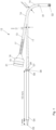
- Fig. 1 shows a simplified side view of an arrangement for operating a biosensor.
- the biosensor is formed here as a sensor fiber 01, which is equipped with immobilized, glucose-sensitive fluorescent phosphors 02 at its free end. When excited with excitation radiation, these fluorescent phosphors emit fluorescent radiation, the intensity of which depends on the glucose concentration in a medium in which the end of the biosensor is positioned.
- the medium can in particular be blood.
- the arrangement for operating the biosensor has an LED chip 03 as an excitation light source, preferably a thin-film LED.
- the LED chip 03 emits the excitation radiation and couples it at a flat angle into a coupling fiber 04.
- the angle between the excitation radiation and the core of the coupling fiber is preferably ⁇ 30°.
- the LED 03 in the embodiment shown is positioned approximately 1 mm away from the entry surface of the coupling fiber 04.
- the entry surface of the coupling fiber can be designed as a freeform surface, spherical, aspherical or flat surface.
- the coupling fiber 04 has, for example, a diameter of 0.5 mm and a length of 10 mm.
- the exit surface of the coupling fiber 04 is attached to a carrier glass 07 with an adhesive 06.
- the carrier glass 07 is equipped with one or more filter layers 08 in order to act as a cut-off filter and to filter out the wavelength of the fluorescence radiation emitted by the fluorescent phosphors 02 from the excitation radiation.
- the carrier glass 07 is followed by a first piece of colored glass 09, which supports the effect of the cut-off filter.
- the first colored glass piece 09 is designed in the form of a waveguide and is connected on the opposite side to an excitation arm 11 of an optical Y-coupler 12.
- the excitation arm 11 and the first colored glass piece 09 have a cross-section that tapers in the direction of radiation.
- the diameter of the excitation arm 11 at its end facing away from the coupling fiber 04 is therefore only 0.1 to 0.2 mm, for example.
- the Y-coupler 12 also has a detector arm 13 and a sensor base 14.
- the excitation arm 11 enters the material that otherwise runs from the detector arm 13 to the sensor base 14.
- the detector arm 13 and the excitation arm 11 form an angle in the range of 5° to 70°, preferably 5° to 30°, particularly preferably about 15°.
- the main beam axis of the detector arm 13 and the sensor base 14 run coaxially in the embodiment shown. In modified versions, the main beam axes of the detector arm and of the sensor base can also run at an angle to one another, for example with an angle change of 10° to 40°.
- the sensor base 14 is designed to be flexible or curved at its end facing away from the connection point 16 in order to be able to be connected to the sensor fiber 01.
- the detector arm 13 and the sensor base 14 have a diameter of 0.5 mm, for example.
- the excitation radiation is guided from the LED chip 03 via the coupling fiber 04, the excitation arm 11 and the sensor base 14 into the sensor fiber 01, where it excites the fluorescent phosphors 02.
- the fluorescent radiation emitted by these runs through the sensor fiber 01 back to the sensor base 14 of the Y-coupler 12 and then mostly into the detector arm 13.
- An optical lens 18 is provided for collimating the fluorescent radiation emerging from the exit surface of the second piece of colored glass 17, which is followed by a further filter 19 in order to allow only the fluorescent radiation to pass to a subsequent detector 21.
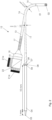
- Fig. 2 shows a modified embodiment of the arrangement for operating the biosensor, which initially corresponds to the structure according to Fig. 1 largely coincides.
- the detector is divided into two partial detectors 21a and 21b, which serve to detect different wavelengths of the fluorescence radiation.
- a beam splitter 22 is located in the beam direction behind the filter 19, which splits the fluorescence radiation into two partial beams depending on the wavelength, which then partial detectors 21a, 21b.
- the second colored glass piece 17 supports the effect of the filter 19.
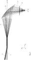
- Fig. 3 shows an example of the optical beam path in the excitation arm 11, in the detector arm 13, in the area of the connection point 16 and especially in the sensor base 14.
- the sensor base 14 serves to deflect the beam and couple it into or out of the sensor fiber and at the same time creates the possibility of a distance of several 100 ⁇ m between the sensor base and the sensor fiber, which makes positioning considerably easier.
- the sensor base 14 is preferably curved or bent in order to be able to be easily connected to the sensor fiber 01 and to realize a beam deflection.
- the entry surface on the excitation arm 11 and the exit surface on the sensor base 14 are thus at an angle of more than 45°, preferably about 90° to each other.
- the connection point 16 is particularly preferably optically designed in the manner of a funnel, as is the beam path in Fig. 3 clarified.
- connection point 16 also results in a great advantage for the optical return path, i.e. the path of the fluorescent light that is guided from the sensor fiber 01 back to the detector 21.
- the beam guidance shown allows the optical losses to be minimized up to the point where the excitation arm flows into the detector arm.
- the comparatively low emissions that emanate from the fluorescent phosphors 02 can therefore be evaluated particularly well on the detector. This allows a distance of several 100 ⁇ m to be achieved between the sensor base and the sensor fiber, which is a great advantage for practical structures.
- a lens 23 is formed on the side of the sensor base 14 facing the sensor fiber 01, preferably integrated into the material of the sensor base.
- the lens 23 is located behind the toric surface in the direction of the excitation radiation in order to focus the excitation radiation onto the input face of the sensor fiber 01.
- the lens can be formed as a spherical or aspherical lens and can be anti-reflective if necessary.
- the numerical aperture which results after the lens 23 on the sensor base 14 in the direction of the sensor fiber 01 is adapted such that it substantially corresponds to the numerical aperture of the sensor fiber.
- the excitation arm 11 widens in diameter in the area of the connection point 16, as can be seen in the steel profile in Fig. 3
- This widening preferably takes place by linear, alternatively by non-linear increase in diameter in the direction of the sensor base 14.
- the surface lines of the cone of the widening resulting in the longitudinal section can thus have any shape.
- the reflection on the toric surface preferably takes place as total reflection.
- an additional reflective layer can be applied in this area. This is useful. If the refractive index of the material in the sensor base is too small, then total reflection is not possible. In this case, an additional reflective layer can be applied to the toric surface.
- This design ensures that the excitation radiation runs from the excitation arm 11 through the widening in the area of the connection point 16 and toric surface 24 to the lens 23 in the material of the excitation arm. Only at the lens 23 does a transition to air or gas occur and then into the sensor fiber 01.
Landscapes
- Health & Medical Sciences (AREA)
- Life Sciences & Earth Sciences (AREA)
- Physics & Mathematics (AREA)
- Pathology (AREA)
- General Health & Medical Sciences (AREA)
- Engineering & Computer Science (AREA)
- Biomedical Technology (AREA)
- Molecular Biology (AREA)
- Medical Informatics (AREA)
- Surgery (AREA)
- Animal Behavior & Ethology (AREA)
- Public Health (AREA)
- Heart & Thoracic Surgery (AREA)
- Biophysics (AREA)
- Veterinary Medicine (AREA)
- Chemical & Material Sciences (AREA)
- Immunology (AREA)
- General Physics & Mathematics (AREA)
- Biochemistry (AREA)
- Analytical Chemistry (AREA)
- Optics & Photonics (AREA)
- Hematology (AREA)
- Emergency Medicine (AREA)
- Nuclear Medicine, Radiotherapy & Molecular Imaging (AREA)
- Urology & Nephrology (AREA)
- Biotechnology (AREA)
- Diabetes (AREA)
- General Chemical & Material Sciences (AREA)
- Cell Biology (AREA)
- Microbiology (AREA)
- Chemical Kinetics & Catalysis (AREA)
- Food Science & Technology (AREA)
- Medicinal Chemistry (AREA)
- Investigating, Analyzing Materials By Fluorescence Or Luminescence (AREA)
- Measurement Of The Respiration, Hearing Ability, Form, And Blood Characteristics Of Living Organisms (AREA)
- Investigating Or Analysing Biological Materials (AREA)
- Investigating Or Analysing Materials By The Use Of Chemical Reactions (AREA)
- Optical Couplings Of Light Guides (AREA)
Claims (15)
- Agencement pour faire fonctionner un biocapteur (01), qui émet un rayonnement, comprenant :- une source de lumière d'excitation (03), laquelle produit au moins un rayonnement d'excitation pour le biocapteur,- une fibre d'accouplement (04), à la surface d'incidence de laquelle est injecté le rayonnement d'excitation,- un détecteur optique (21), et- un coupleur optique en Y (12) avec un bras d'excitation (11), qui est raccordé à la surface de sortie de la fibre d'accouplement (04), un bras de détecteur (13), qui est raccordé au détecteur optique (21) et un pied de capteur (14), lequel peut être raccordé au biocapteur (01),sachant que le bras d'excitation (11) comporte une forme conique, sachant que l'axe de faisceau du bras d'excitation (11) forme avec l'axe de faisceau principal du bras de détecteur (13) un angle compris à un emplacement de liaison (16) entre le bras de détecteur (13) et le bras d'excitation (11) dans une plage de 5° à 70°, sachant que le diamètre du bras d'excitation (11) au point de raccordement (16) avec le bras de détecteur (13) comporte moins de deux tiers du diamètre du bras de détecteur (13) et sachant que le bras d'excitation (11) comporte une section transversale se réduisant en direction du rayonnement.
- Agencement selon la revendication 1, caractérisé en ce que le diamètre du bras d'excitation (11) au point de raccordement (16) est inférieur de la moitié de sa surface d'incidence.
- Agencement selon la revendication 1 ou 2, caractérisé en ce que le bras de détecteur (13) et le pied de capteur (14) comportent un axe de faisceau principal commun.
- Agencement selon l'une quelconque des revendications 1 à 3, caractérisé en ce que la source de lumière d'excitation (03) est une puce à DEL (diodes électroluminescentes), dont le plan d'émission de la surface d'incidence de la fibre d'accouplement (04) est positionné à une distance qui est de 0,1 à 10 fois le diamètre de la fibre d'accouplement (04).
- Agencement selon la revendication 4, caractérisé en ce que la fibre d'accouplement (04) possède une longueur, qui comporte 7 fois à 13 fois la distance entre la source de lumière d'excitation (03) et la surface d'incidence de la fibre d'accouplement (04), se situe en particulier dans une plage de 7 à 13 mm.
- Agencement selon la revendication 4, caractérisé en ce que la surface d'incidence de la fibre d'accouplement (04) est constituée sous la forme d'une surface plane, sphérique, asphérique ou sous la forme d'une surface de forme libre.
- Agencement selon l'une quelconque des revendications 1 à 6, caractérisé en ce qu'un filtre de coupure (07, 08) est disposé entre la surface de sortie de la fibre d'accouplement (04) et la surface d'incidence du bras d'excitation (11), lequel exfiltre du rayonnement d'excitation la longueur d'ondes du rayonnement pouvant être émis par le biocapteur (01).
- Agencement selon l'une quelconque des revendications 1 à 7, caractérisé en ce que la fibre d'accouplement (04) est constituée avec un axe longitudinal passant en ligne droite.
- Agencement selon la revendication 7 ou selon la revendication 8 dépendante de la revendication 7, caractérisé en ce que le filtre de coupure est composé d'un verre porteur (07) avec des couches de filtrage (08) optiques appliquées dessus, sachant que la surface de sortie de la fibre d'accouplemené (04) est collée de préférence sur les couches de filtrage (08).
- Agencement selon l'une quelconque des revendications 1 à 9, caractérisé en ce qu'une lentille (18) de collimation du rayonnement émis par le biocapteur (01) est disposée entre la surface de sortie du bras de détecteur (13) et le détecteur (21), sachant qu'un filtre optique (19) est disposé entre la lentille (18) et le détecteur (21), lequel bloque les parties incidentes du rayonnement d'excitation.
- Agencement selon l'une quelconque des revendications 1 à 10, caractérisé en ce qu'un élément de verre coloré (17) dans la forme de guide d'ondes est disposé à l'extrémité du bras de détecteur (13) du côté sortie.
- Agencement selon l'une quelconque des revendications 1 à 11, caractérisé en ce que le pied de capteur (14) comprend une section courbe dans laquelle a lieu une déviation de rayonnement avec un angle de plus de 45°, de préférence à peu près 90°.
- Agencement selon la revendication 12, caractérisé en ce qu'une surface torique (24) déviant le rayonnement est constituée dans le pied de capteur (14).
- Agencement selon l'une quelconque des revendications 1 à 13, caractérisé en ce qu'il est constitué en plus pour déterminer la teneur en glucose, en particulier dans le sang et comprend le biocapteur (01, 02), qui peut être implanté dans un tissu et émet un rayonnement lors de l'excitation.
- Agencement selon la revendication 14, caractérisé en ce que le biocapteur est formé sous la forme d'une fibre optique (01), laquelle possède sur sa surface de sortie des substances électroluminescentes sensibles au glucose (02), qui émettent lors de l'excitation avec le rayonnement d'excitation un rayonnement fluorescent avec une longueur d'onde de fluorescence.
Applications Claiming Priority (2)
| Application Number | Priority Date | Filing Date | Title |
|---|---|---|---|
| DE102019133365.2A DE102019133365A1 (de) | 2019-12-06 | 2019-12-06 | Anordnung zum Betrieb eines Biosensors sowie Anordnung zur Bestimmung des Glukosegehalts im Blut |
| PCT/EP2020/084747 WO2021110977A1 (fr) | 2019-12-06 | 2020-12-04 | Agencement pour faire fonctionner un biocapteur et agencement pour déterminer la teneur en glucose dans le sang |
Publications (2)
| Publication Number | Publication Date |
|---|---|
| EP4070077A1 EP4070077A1 (fr) | 2022-10-12 |
| EP4070077B1 true EP4070077B1 (fr) | 2024-12-25 |
Family
ID=73790070
Family Applications (1)
| Application Number | Title | Priority Date | Filing Date |
|---|---|---|---|
| EP20821150.8A Active EP4070077B1 (fr) | 2019-12-06 | 2020-12-04 | Dispositif pour le fonctionnement d'un biocapteur et dispositif pour la détermination de la teneur en glucose du sang |
Country Status (8)
| Country | Link |
|---|---|
| US (1) | US20230011856A1 (fr) |
| EP (1) | EP4070077B1 (fr) |
| JP (1) | JP7741072B2 (fr) |
| CN (1) | CN115053120B (fr) |
| AU (1) | AU2020395508B2 (fr) |
| DE (1) | DE102019133365A1 (fr) |
| ES (1) | ES3014721T3 (fr) |
| WO (1) | WO2021110977A1 (fr) |
Family Cites Families (22)
| Publication number | Priority date | Publication date | Assignee | Title |
|---|---|---|---|---|
| US4344438A (en) | 1978-08-02 | 1982-08-17 | The United States Of America As Represented By The Department Of Health, Education And Welfare | Optical sensor of plasma constituents |
| US4496211A (en) * | 1980-12-05 | 1985-01-29 | Maurice Daniel | Lightpipe network with optical devices for distributing electromagnetic radiation |
| JPS57144516A (en) * | 1981-03-03 | 1982-09-07 | Canon Inc | Scan optical system having fall compensating function |
| JPH0387807A (ja) * | 1989-08-31 | 1991-04-12 | Toshiba Corp | 走査式光学装置 |
| JPH04345102A (ja) * | 1991-05-22 | 1992-12-01 | Nippon Telegr & Teleph Corp <Ntt> | 狭帯域フィルタ |
| JPH06324274A (ja) * | 1993-01-20 | 1994-11-25 | Asahi Optical Co Ltd | 走査光学系 |
| US5341805A (en) * | 1993-04-06 | 1994-08-30 | Cedars-Sinai Medical Center | Glucose fluorescence monitor and method |
| DE4322734A1 (de) | 1993-07-08 | 1995-01-12 | Hoechst Ag | Optischer Y-Koppler |
| DE4341086A1 (de) * | 1993-12-02 | 1995-06-08 | Hoechst Ag | Optischer Y-Koppler |
| AU697467B2 (en) * | 1994-12-28 | 1998-10-08 | Ire-Polus Co. | A coupling arrangement between a multi-mode light source and an optical fiber through an intermediate optical fiber length |
| JP2897742B2 (ja) * | 1996-11-27 | 1999-05-31 | 日本電気株式会社 | 光送受信モジュール |
| JP3543923B2 (ja) * | 1997-12-25 | 2004-07-21 | 富士写真フイルム株式会社 | グルコース濃度測定装置 |
| JP2001124945A (ja) | 1999-10-28 | 2001-05-11 | Oki Electric Ind Co Ltd | Y分岐導波路 |
| US7226414B2 (en) * | 2002-10-09 | 2007-06-05 | Biotex, Inc. | Method and apparatus for analyte sensing |
| JP2004264339A (ja) * | 2003-01-30 | 2004-09-24 | Sony Corp | 光導波路および光送受信モジュール |
| US7496245B2 (en) * | 2004-08-20 | 2009-02-24 | Research International, Inc. | Misalignment compensating optical sensor and method |
| EP2120680A2 (fr) * | 2007-02-06 | 2009-11-25 | Glumetrics, Inc. | Systèmes et procédés optiques pour la mesure ratiométrique de la concentration en glucose dans le sang |
| CA2850304A1 (fr) * | 2011-08-30 | 2013-03-07 | Glumetrics, Inc. | Stockage d'informations pour detecteur d'analytes sterilise |
| EP2948760B1 (fr) | 2013-01-22 | 2022-10-05 | Embecta Corp. | Coupleur optique de taille réduite pour une détection fluorimétrique |
| DE102013020216A1 (de) * | 2013-12-12 | 2015-07-02 | Christopher Matheisen | Auslegermikrostrukturbauelement zur optischen Erzeugung von elekromagnetischen Signalen im Terahertzfrequenzbereich |
| DE102014005219A1 (de) * | 2014-03-28 | 2015-10-01 | Josip Mihaljevic | Verfahren und System zum Bilden einer optischen Falle |
| DE102015101847B4 (de) | 2015-02-10 | 2017-11-02 | Eyesense Gmbh | Strahlteiler und Anordnung zur Untersuchung einer mittels elektromagnetischer Strahlung anregbaren Probe |
-
2019
- 2019-12-06 DE DE102019133365.2A patent/DE102019133365A1/de not_active Ceased
-
2020
- 2020-12-04 JP JP2022532871A patent/JP7741072B2/ja active Active
- 2020-12-04 WO PCT/EP2020/084747 patent/WO2021110977A1/fr not_active Ceased
- 2020-12-04 US US17/782,397 patent/US20230011856A1/en active Pending
- 2020-12-04 AU AU2020395508A patent/AU2020395508B2/en active Active
- 2020-12-04 EP EP20821150.8A patent/EP4070077B1/fr active Active
- 2020-12-04 CN CN202080083508.6A patent/CN115053120B/zh active Active
- 2020-12-04 ES ES20821150T patent/ES3014721T3/es active Active
Also Published As
| Publication number | Publication date |
|---|---|
| DE102019133365A1 (de) | 2021-06-10 |
| WO2021110977A1 (fr) | 2021-06-10 |
| AU2020395508B2 (en) | 2023-11-23 |
| CN115053120A (zh) | 2022-09-13 |
| AU2020395508A1 (en) | 2022-06-23 |
| CA3160535A1 (fr) | 2021-06-10 |
| CN115053120B (zh) | 2026-04-17 |
| ES3014721T3 (en) | 2025-04-24 |
| US20230011856A1 (en) | 2023-01-12 |
| JP7741072B2 (ja) | 2025-09-17 |
| JP2023504498A (ja) | 2023-02-03 |
| EP4070077A1 (fr) | 2022-10-12 |
Similar Documents
| Publication | Publication Date | Title |
|---|---|---|
| DE10311452B4 (de) | Analysesystem zur reagenzienfreien Bestimmung der Konzentration eines Analyten im lebenden Gewebe | |
| EP0876596B1 (fr) | Procede et dispositif de determination d'un analyte contenu dans une matrice de diffusion | |
| DE69636144T2 (de) | Diffus reflektierende sonde | |
| EP1635699B1 (fr) | Element d'essai integre permettant en une seule etape le prelevement et l'analyse d'un echantillon a analyser | |
| DE102018214617A1 (de) | Sensoreinrichtung | |
| AT510765B1 (de) | Vorrichtung zur photometrischen bzw. spektrometrischen untersuchung einer flüssigen probe | |
| WO1999007277A1 (fr) | Dispositif d'analyse pour l'analyse in vivo dans le corps d'un patient | |
| DE10393931T5 (de) | Verbesserung der Faseroptischen Messtechnik unter Verwendung einer Doppelkernfaser | |
| DE10151312A1 (de) | Oberflächenplasmonen-Resonanz-Sensor | |
| DE102007047093B4 (de) | Vorrichtung zur Messung von Fluoreszenzstrahlung an biologischen Substanzen mit einer Halbleitersensorenanordnung | |
| EP2430415B1 (fr) | Spectrometre confocal miniaturise | |
| EP4070077B1 (fr) | Dispositif pour le fonctionnement d'un biocapteur et dispositif pour la détermination de la teneur en glucose du sang | |
| DE102007020078A1 (de) | Vorrichtung zum Sammeln von Streulicht | |
| DE19519051B4 (de) | Verfahren und Vorrichtung zur polarimetrischen Bestimmung der Blutzuckerkonzentration | |
| DE102010029818B4 (de) | Positionssensor | |
| DE4125036C1 (en) | Fibre=optic sensor for measuring refractive index of liq. or gas - measures reflection at free end of optical fibre coated with material of high refractive index using lock-in amplifiers | |
| DE19734618A1 (de) | Analysevorrichtung zur in vivo-Analyse im Körper eines Patienten | |
| DD227044B1 (de) | Vorrichtung zur erfassung des stoffwechselzustandes von lebenden organen | |
| EP3504537B1 (fr) | Dispositif pour mesurer la fluorescence utilisant une carte imprimée avec source de lumière et capteur attachés, la carte imprimée comprenant une fissure pour supprimer la conduction de lumière | |
| DE102013219932B4 (de) | Optische Messvorrichtung und Messverfahren | |
| AT14051U1 (de) | Optochemischer Sensor | |
| WO2019016290A1 (fr) | Capteur optoélectronique | |
| DE102018114969B4 (de) | Verfahren und Vorrichtung zur Einkopplung von Licht in einen Lichtleiter und Sensor | |
| WO2016193066A1 (fr) | Dispositif d'échantillonnage de fluide, fabrication de celui-ci, dispositif d'analyse de fluide et procédé de mesure optique | |
| DE102011085615B4 (de) | ATR Sonde zur Untersuchung eines Mediums mittels einer optischen Strahlung |
Legal Events
| Date | Code | Title | Description |
|---|---|---|---|
| STAA | Information on the status of an ep patent application or granted ep patent |
Free format text: STATUS: UNKNOWN |
|
| STAA | Information on the status of an ep patent application or granted ep patent |
Free format text: STATUS: THE INTERNATIONAL PUBLICATION HAS BEEN MADE |
|
| PUAI | Public reference made under article 153(3) epc to a published international application that has entered the european phase |
Free format text: ORIGINAL CODE: 0009012 |
|
| STAA | Information on the status of an ep patent application or granted ep patent |
Free format text: STATUS: REQUEST FOR EXAMINATION WAS MADE |
|
| 17P | Request for examination filed |
Effective date: 20220704 |
|
| AK | Designated contracting states |
Kind code of ref document: A1 Designated state(s): AL AT BE BG CH CY CZ DE DK EE ES FI FR GB GR HR HU IE IS IT LI LT LU LV MC MK MT NL NO PL PT RO RS SE SI SK SM TR |
|
| DAV | Request for validation of the european patent (deleted) | ||
| DAX | Request for extension of the european patent (deleted) | ||
| GRAP | Despatch of communication of intention to grant a patent |
Free format text: ORIGINAL CODE: EPIDOSNIGR1 |
|
| STAA | Information on the status of an ep patent application or granted ep patent |
Free format text: STATUS: GRANT OF PATENT IS INTENDED |
|
| RIC1 | Information provided on ipc code assigned before grant |
Ipc: G01N 21/77 20060101ALN20240708BHEP Ipc: A61B 5/00 20060101ALI20240708BHEP Ipc: G01N 33/66 20060101ALI20240708BHEP Ipc: A61B 5/1486 20060101ALI20240708BHEP Ipc: A61B 5/145 20060101ALI20240708BHEP Ipc: G01N 21/64 20060101AFI20240708BHEP |
|
| INTG | Intention to grant announced |
Effective date: 20240722 |
|
| GRAS | Grant fee paid |
Free format text: ORIGINAL CODE: EPIDOSNIGR3 |
|
| GRAA | (expected) grant |
Free format text: ORIGINAL CODE: 0009210 |
|
| STAA | Information on the status of an ep patent application or granted ep patent |
Free format text: STATUS: THE PATENT HAS BEEN GRANTED |
|
| AK | Designated contracting states |
Kind code of ref document: B1 Designated state(s): AL AT BE BG CH CY CZ DE DK EE ES FI FR GB GR HR HU IE IS IT LI LT LU LV MC MK MT NL NO PL PT RO RS SE SI SK SM TR |
|
| REG | Reference to a national code |
Ref country code: GB Ref legal event code: FG4D Free format text: NOT ENGLISH |
|
| REG | Reference to a national code |
Ref country code: CH Ref legal event code: EP |
|
| REG | Reference to a national code |
Ref country code: DE Ref legal event code: R096 Ref document number: 502020010071 Country of ref document: DE |
|
| REG | Reference to a national code |
Ref country code: IE Ref legal event code: FG4D Free format text: LANGUAGE OF EP DOCUMENT: GERMAN |
|
| REG | Reference to a national code |
Ref country code: LT Ref legal event code: MG9D |
|
| PG25 | Lapsed in a contracting state [announced via postgrant information from national office to epo] |
Ref country code: HR Free format text: LAPSE BECAUSE OF FAILURE TO SUBMIT A TRANSLATION OF THE DESCRIPTION OR TO PAY THE FEE WITHIN THE PRESCRIBED TIME-LIMIT Effective date: 20241225 |
|
| PG25 | Lapsed in a contracting state [announced via postgrant information from national office to epo] |
Ref country code: FI Free format text: LAPSE BECAUSE OF FAILURE TO SUBMIT A TRANSLATION OF THE DESCRIPTION OR TO PAY THE FEE WITHIN THE PRESCRIBED TIME-LIMIT Effective date: 20241225 |
|
| PG25 | Lapsed in a contracting state [announced via postgrant information from national office to epo] |
Ref country code: BG Free format text: LAPSE BECAUSE OF FAILURE TO SUBMIT A TRANSLATION OF THE DESCRIPTION OR TO PAY THE FEE WITHIN THE PRESCRIBED TIME-LIMIT Effective date: 20241225 |
|
| PG25 | Lapsed in a contracting state [announced via postgrant information from national office to epo] |
Ref country code: NO Free format text: LAPSE BECAUSE OF FAILURE TO SUBMIT A TRANSLATION OF THE DESCRIPTION OR TO PAY THE FEE WITHIN THE PRESCRIBED TIME-LIMIT Effective date: 20250325 |
|
| PG25 | Lapsed in a contracting state [announced via postgrant information from national office to epo] |
Ref country code: GR Free format text: LAPSE BECAUSE OF FAILURE TO SUBMIT A TRANSLATION OF THE DESCRIPTION OR TO PAY THE FEE WITHIN THE PRESCRIBED TIME-LIMIT Effective date: 20250326 Ref country code: LV Free format text: LAPSE BECAUSE OF FAILURE TO SUBMIT A TRANSLATION OF THE DESCRIPTION OR TO PAY THE FEE WITHIN THE PRESCRIBED TIME-LIMIT Effective date: 20241225 |
|
| REG | Reference to a national code |
Ref country code: ES Ref legal event code: FG2A Ref document number: 3014721 Country of ref document: ES Kind code of ref document: T3 Effective date: 20250424 |
|
| PG25 | Lapsed in a contracting state [announced via postgrant information from national office to epo] |
Ref country code: RS Free format text: LAPSE BECAUSE OF FAILURE TO SUBMIT A TRANSLATION OF THE DESCRIPTION OR TO PAY THE FEE WITHIN THE PRESCRIBED TIME-LIMIT Effective date: 20250325 |
|
| REG | Reference to a national code |
Ref country code: NL Ref legal event code: MP Effective date: 20241225 |
|
| PG25 | Lapsed in a contracting state [announced via postgrant information from national office to epo] |
Ref country code: NL Free format text: LAPSE BECAUSE OF FAILURE TO SUBMIT A TRANSLATION OF THE DESCRIPTION OR TO PAY THE FEE WITHIN THE PRESCRIBED TIME-LIMIT Effective date: 20241225 |
|
| PG25 | Lapsed in a contracting state [announced via postgrant information from national office to epo] |
Ref country code: SM Free format text: LAPSE BECAUSE OF FAILURE TO SUBMIT A TRANSLATION OF THE DESCRIPTION OR TO PAY THE FEE WITHIN THE PRESCRIBED TIME-LIMIT Effective date: 20241225 |
|
| PG25 | Lapsed in a contracting state [announced via postgrant information from national office to epo] |
Ref country code: PL Free format text: LAPSE BECAUSE OF FAILURE TO SUBMIT A TRANSLATION OF THE DESCRIPTION OR TO PAY THE FEE WITHIN THE PRESCRIBED TIME-LIMIT Effective date: 20241225 |
|
| PG25 | Lapsed in a contracting state [announced via postgrant information from national office to epo] |
Ref country code: IS Free format text: LAPSE BECAUSE OF FAILURE TO SUBMIT A TRANSLATION OF THE DESCRIPTION OR TO PAY THE FEE WITHIN THE PRESCRIBED TIME-LIMIT Effective date: 20250425 |
|
| PG25 | Lapsed in a contracting state [announced via postgrant information from national office to epo] |
Ref country code: PT Free format text: LAPSE BECAUSE OF FAILURE TO SUBMIT A TRANSLATION OF THE DESCRIPTION OR TO PAY THE FEE WITHIN THE PRESCRIBED TIME-LIMIT Effective date: 20250428 |
|
| PG25 | Lapsed in a contracting state [announced via postgrant information from national office to epo] |
Ref country code: EE Free format text: LAPSE BECAUSE OF FAILURE TO SUBMIT A TRANSLATION OF THE DESCRIPTION OR TO PAY THE FEE WITHIN THE PRESCRIBED TIME-LIMIT Effective date: 20241225 |
|
| PG25 | Lapsed in a contracting state [announced via postgrant information from national office to epo] |
Ref country code: RO Free format text: LAPSE BECAUSE OF FAILURE TO SUBMIT A TRANSLATION OF THE DESCRIPTION OR TO PAY THE FEE WITHIN THE PRESCRIBED TIME-LIMIT Effective date: 20241225 |
|
| PG25 | Lapsed in a contracting state [announced via postgrant information from national office to epo] |
Ref country code: SK Free format text: LAPSE BECAUSE OF FAILURE TO SUBMIT A TRANSLATION OF THE DESCRIPTION OR TO PAY THE FEE WITHIN THE PRESCRIBED TIME-LIMIT Effective date: 20241225 |
|
| PG25 | Lapsed in a contracting state [announced via postgrant information from national office to epo] |
Ref country code: CZ Free format text: LAPSE BECAUSE OF FAILURE TO SUBMIT A TRANSLATION OF THE DESCRIPTION OR TO PAY THE FEE WITHIN THE PRESCRIBED TIME-LIMIT Effective date: 20241225 |
|
| PG25 | Lapsed in a contracting state [announced via postgrant information from national office to epo] |
Ref country code: SE Free format text: LAPSE BECAUSE OF FAILURE TO SUBMIT A TRANSLATION OF THE DESCRIPTION OR TO PAY THE FEE WITHIN THE PRESCRIBED TIME-LIMIT Effective date: 20241225 |
|
| REG | Reference to a national code |
Ref country code: DE Ref legal event code: R097 Ref document number: 502020010071 Country of ref document: DE |
|
| PG25 | Lapsed in a contracting state [announced via postgrant information from national office to epo] |
Ref country code: DK Free format text: LAPSE BECAUSE OF FAILURE TO SUBMIT A TRANSLATION OF THE DESCRIPTION OR TO PAY THE FEE WITHIN THE PRESCRIBED TIME-LIMIT Effective date: 20241225 |
|
| PLBE | No opposition filed within time limit |
Free format text: ORIGINAL CODE: 0009261 |
|
| STAA | Information on the status of an ep patent application or granted ep patent |
Free format text: STATUS: NO OPPOSITION FILED WITHIN TIME LIMIT |
|
| 26N | No opposition filed |
Effective date: 20250926 |
|
| PGFP | Annual fee paid to national office [announced via postgrant information from national office to epo] |
Ref country code: DE Payment date: 20251124 Year of fee payment: 6 |
|
| PGFP | Annual fee paid to national office [announced via postgrant information from national office to epo] |
Ref country code: GB Payment date: 20251218 Year of fee payment: 6 |
|
| PGFP | Annual fee paid to national office [announced via postgrant information from national office to epo] |
Ref country code: FR Payment date: 20251218 Year of fee payment: 6 |
|
| PGFP | Annual fee paid to national office [announced via postgrant information from national office to epo] |
Ref country code: ES Payment date: 20260119 Year of fee payment: 6 |
|
| PGFP | Annual fee paid to national office [announced via postgrant information from national office to epo] |
Ref country code: IT Payment date: 20251231 Year of fee payment: 6 |