EP4070094B1 - Procédé de fonctionnement d'un dispositif d'analyse de gaz respiratoire comportant au moins un capteur de gaz - Google Patents
Procédé de fonctionnement d'un dispositif d'analyse de gaz respiratoire comportant au moins un capteur de gaz Download PDFInfo
- Publication number
- EP4070094B1 EP4070094B1 EP20816941.7A EP20816941A EP4070094B1 EP 4070094 B1 EP4070094 B1 EP 4070094B1 EP 20816941 A EP20816941 A EP 20816941A EP 4070094 B1 EP4070094 B1 EP 4070094B1
- Authority
- EP
- European Patent Office
- Prior art keywords
- humidity
- gas
- sensor
- respiratory gas
- respiratory
- Prior art date
- Legal status (The legal status is an assumption and is not a legal conclusion. Google has not performed a legal analysis and makes no representation as to the accuracy of the status listed.)
- Active
Links
Images

Classifications
-
- G—PHYSICS
- G01—MEASURING; TESTING
- G01N—INVESTIGATING OR ANALYSING MATERIALS BY DETERMINING THEIR CHEMICAL OR PHYSICAL PROPERTIES
- G01N33/00—Investigating or analysing materials by specific methods not covered by groups G01N1/00 - G01N31/00
- G01N33/48—Biological material, e.g. blood, urine; Haemocytometers
- G01N33/483—Physical analysis of biological material
- G01N33/497—Physical analysis of biological material of gaseous biological material, e.g. breath
-
- G—PHYSICS
- G01—MEASURING; TESTING
- G01N—INVESTIGATING OR ANALYSING MATERIALS BY DETERMINING THEIR CHEMICAL OR PHYSICAL PROPERTIES
- G01N33/00—Investigating or analysing materials by specific methods not covered by groups G01N1/00 - G01N31/00
- G01N33/0004—Gaseous mixtures, e.g. polluted air
- G01N33/0009—General constructional details of gas analysers, e.g. portable test equipment
- G01N33/0022—General constructional details of gas analysers, e.g. portable test equipment using a number of analysing channels
- G01N33/0024—General constructional details of gas analysers, e.g. portable test equipment using a number of analysing channels a chemical reaction taking place or a gas being eliminated in one or more channels
-
- G—PHYSICS
- G01—MEASURING; TESTING
- G01N—INVESTIGATING OR ANALYSING MATERIALS BY DETERMINING THEIR CHEMICAL OR PHYSICAL PROPERTIES
- G01N33/00—Investigating or analysing materials by specific methods not covered by groups G01N1/00 - G01N31/00
- G01N33/0004—Gaseous mixtures, e.g. polluted air
- G01N33/0009—General constructional details of gas analysers, e.g. portable test equipment
- G01N33/0027—General constructional details of gas analysers, e.g. portable test equipment concerning the detector
- G01N33/0036—General constructional details of gas analysers, e.g. portable test equipment concerning the detector specially adapted to detect a particular component
- G01N33/0059—Avoiding interference of a gas with the gas to be measured
- G01N33/006—Avoiding interference of water vapour with the gas to be measured
Definitions
- the present invention relates to a method for operating a respiratory gas analyzer with at least one gas sensor, wherein the respiratory gas analyzer comprises at least one humidity-regulating system element arranged in a switchable, parallel air guide path. Furthermore, the invention relates to the use of a humidity-regulating system element arranged in a switchable, parallel air guide path of a respiratory gas analyzer with at least one gas sensor for checking the humidity state of the gas sensor, as well as to a correspondingly configured respiratory gas analyzer.
- the air exhaled by a person contains various substances (biomarkers) of medical and, in particular, diagnostic interest.
- the nitrogen monoxide content in exhaled air can be examined to detect inflammatory processes or chronic pulmonary diseases, such as bronchial asthma.
- Exhaled air can be analyzed using respiratory gas analyzers equipped with appropriate sensors, particularly gas sensors. NO and/or NO2 sensors are primarily used here to measure the concentration of these substances in exhaled air.
- gas sensors are generally sensitive to external influences, meaning that, for example, varying ambient humidity and temperature can affect measurement accuracy. Storage effects can therefore also occur on gas sensors, with the sensor's sensitivity changing over time depending on the storage conditions and affecting the measurement signal. In this context, the humidity that develops at the sensor plays a particularly important role.
- JP2019184571 discloses a respiratory gas analyzer with gas sensors and a humidity sensor as well as a humidity regulating element, wherein gas samples are guided via an air guide path with the humidity regulating element and via an air guide path without the humidity regulating element.
- the proposed method serves to operate a respiratory gas analyzer with at least one gas sensor, wherein the humidity state of the gas sensor is checked.
- the respiratory gas analyzer is equipped with at least one humidity-regulating system element arranged in a switchable, parallel air duct path.
- a switchable, parallel air duct path here means that an additional air duct path is provided that does not run via the humidity-regulating system element.
- the air duct for the actual gas analytical measurement at the gas sensor generally runs via this additional air duct path.
- Such a respiratory gas analyzer can, for example, be configured for the analysis of nitrogen species and, in particular, be equipped with NO/ NO2 sensors.
- the gas sensor can, for example, be an electrochemical gas sensor or a sensor based on field-effect transistors (FETs).
- known respiratory gas analyzers for example, utilize Nafion tubes that adapt the humidity of the gas sample to the ambient humidity.
- Such complex solutions which are generally difficult to miniaturize, can be dispensed with using the proposed method, since the proposed method allows the respiratory gas analyzer to more or less independently detect the potentially variable humidity state of the gas sensor, allowing measures to be derived to correct the sensor state or, if necessary, compensate for interference.
- the proposed method generates a signal based on a difference in humidity between airflow with and without humidity regulation.
- the humidity level at the sensor is determined indirectly, so to speak, by passing a gas sample over the humidity-regulating system element (humidity regulator) before it reaches the gas sensor.
- the gas properties altered by the humidity-regulating system element serve to generate signals or characteristics that provide information about the humidity level in the area of the sensor.
- the humidity level of the sensor is not measured directly, which would generally be very difficult when using gas-sensitive layers, for example, in the size range of a few 100 nm thick.
- the humidity level of the gas sensor is inferred from the properties of the humidity regulator, whereby a correlation between the absorption capacity of the humidity-regulating system element (e.g., activated carbon) and the humidity level of the sensor is used for the purposes of the invention.
- the humidity-regulating system element e.g., activated carbon
- the humidity-regulating system element removes moisture from the gas sample.
- the humidity of the gas sample is influenced to a greater or lesser extent. This effect can be measured directly or indirectly in comparison with an air flow without humidity regulation.
- the gas sample is temporarily passed through the humidity-regulating system element and temporarily not through the humidity-regulating
- the difference in the different influence of the humidity-regulating system element on the gas sample can be detected.
- a different humidity X is established at the gas sensor.
- a humidity jump of amplitude ⁇ X occurs, which can be used to determine the humidity level in the area of the gas sensor.
- Switching between the air flow path with a humidity-regulating system element and the air flow path without a humidity-regulating system element can be achieved, for example, by selectively switching corresponding valves or pumps.
- Corresponding arrangements are known in principle in the prior art, with such parallel air flow paths conventionally being used to eliminate interference by appropriate system elements and, for example, to remove certain substances from the gas sample and partially purify the gas.
- the proposed method uses the parallel air flow paths to enable indirect measurement of the humidity at the gas sensor and thus compensate for its influence on measurement accuracy or to initiate other measures.
- the measures that may need to be initiated may, for example, include blocking the respiratory gas analyzer for further measurements and/or recalibrating the respiratory gas analyzer and/or drying the gas sensor in particular and/or drying the humidity-regulating system element and/or correcting the measured value of a respiratory gas analysis measurement.
- the initiation of such measures may, for example, be made dependent on the measurable difference exceeding or falling below a certain threshold. Exceeding or falling below a predefined threshold for the measurable difference then indicates that a certain level of humidity is present in the area of the gas sensor, which is influencing the measurement signal, so that sufficient measurement accuracy or, in some cases, even the full functionality of the gas sensor can no longer be assumed.
- the evaluation may also stipulate that the measurable difference must lie between two predefined threshold values in order to demonstrate a humidity level that ensures sufficient measurement accuracy.
- the proposed method is expediently implemented in such a way that the humidity level is checked regularly.
- specific time intervals can be specified to ensure operational readiness with sufficient measurement accuracy at all times.
- it can also be planned to perform a check regularly after a certain storage period of the respiratory gas analyzer.
- the invention comprises a respiratory gas analyzer with at least one gas sensor and at least one humidity sensor as well as at least one humidity-regulating system element arranged in a switchable, parallel air guide path.
- This respiratory gas analyzer is characterized in that the respiratory gas analyzer is designed to carry out the described method.
- the respiratory gas analyzer is equipped with a corresponding control system that guides the gas sample via the air guide path with the humidity-regulating system element and in a time-dependent manner. Before or after, the gas sample can be guided through the airflow path without a humidity-regulating system element. In principle, it is also possible for the gas sample to be guided through both airflow paths in parallel, at least temporarily.
- a corresponding evaluation of the measurable difference is provided in the manner described above, whereby this difference is based on measurements from the gas sensor or on measurements from the humidity sensor provided in the device during airflow with and without humidity regulation.
- Properties of the gas sample are determined using suitable sensors as it enters the device. It can be particularly advantageous to use the measured humidity to check whether the desired dehumidification performance of a mouthpiece in use is sufficient. If the measured dehumidification performance is insufficient, for example, the user can be prompted to change the mouthpiece.
- the gas sample is passed through the humidity-regulating system element 3 to check the humidity level at the gas sensor.
- the gas sample is passed through path 11 by appropriately switching valves or pumps through the humidity-regulating system element 3.
- the humidity-regulating system element is preferably a humidity regulator with activated carbon, which, in addition to humidity regulation, also has a gas-filtering function that can also be used for other purposes. If the device was stored in a very humid environment before the measurement, the activated carbon releases moisture into the gas sample. If the device was stored in a dry environment before the measurement, the activated carbon removes moisture from the gas sample.
- the moisture content of the gas sample is influenced to a greater or lesser extent.
- the humidity of the gas sample upon arrival at the gas sensor 4 is measured in the Fig. 1 indicated by X and can usually be specified as relative or absolute humidity.
- the gas sample is temporarily guided via path 11 and temporarily via path 12, the actual measurement path without humidity regulation. It is particularly useful to first guide the gas sample via path 11 and then via path 12, so that switching is not necessary for the actual gas analytical measurement at gas sensor 4. As a rule, it is sufficient if the gas sample is first guided via path 11 and then via path 12 for a few seconds.
- the gas sample is guided past humidity regulator 3, resulting in a humidity jump of amplitude ⁇ X.
- the humidity state of the gas sensor can be deduced from ⁇ X.
- humidity X rises suddenly to a higher value when switching to path 12. From this, it can be concluded that the device was stored in a dry place because the humidity regulator was able to remove the moisture from the gas sample. How the humidity jump is actually evaluated depends on the switching direction of the air guide paths and the mathematical evaluation method. In general, it can be assumed that when the device is stored in a dry environment, the humidity regulator reaches its full capacity, and therefore a significant humidity jump can be expected when switching between the airflow paths. In this case, the humidity level at the gas sensor is normal due to the dry storage conditions.
- the actual determination of the humidity state at the gas sensor takes place.
- the humidity state of the sensor can also be determined in particular using a dedicated humidity sensor 5, wherein the humidity sensor 5 can be connected upstream or downstream of the gas sensor 4. Depending on the evaluation method, the humidity sensor can measure either the humidity X directly or the humidity jump ⁇ X.
- any necessary corrective and/or compensation measures can be initiated if the humidity level falls outside specified limits. If predefined limits for the humidity level are exceeded or undershot, for example, the device can be blocked for further measurements, a request for recalibration of the device can be issued, the gas sensor can be dried, for example, by actively heating it using an integrated heating element (if provided), or the measured value of a breath gas analysis measurement can be corrected depending on the humidity level of the gas sensor.
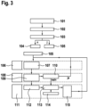
- Fig. 3 illustrates, by way of example, a flowchart for detecting and correcting the humidity status of the gas sensor in a respiratory gas analyzer.
- an initial check 102 of the device is performed, in particular asking whether a maximum tolerable storage time has been exceeded, whether the time is set and whether a battery change should be carried out, or whether other parameters indicate that the device was stored under unfavorable environmental conditions.
- Step 102 is used to check whether the device has not been used for a long time and could therefore be in a changed and/or critical humidity status.
- step 103 asks whether a humidity check or a check of the humidity status of the gas sensor is required.
- step 104 the device is ready for measurement (step 104). If query 103 indicates that a humidity check is required, the actual check of the humidity status is started with step 105.
- the start of the moisture status check 105 is shown in the lower part of the flow chart of the Fig. 3 shown again separately.
- a pseudo-measurement 106 is carried out by sucking in air from the environment.
- the current device status is checked in step 107.
- the mouthpiece status is checked in step 109 and in step 110 it is determined whether a new mouthpiece is required. If this is the case, after replacing the mouthpiece, a return to step 106 occurs.
- step 111 the system proceeds to the third phase 111. If necessary, the step can be started directly from 109 to the third phase 111.
- step 112 ⁇ X is used to analyze in the manner described above whether the humidity level of the gas sensor exceeds or falls below predefined limit values. Based on this analysis, step 113 queries whether any resulting measures are required, such as baking out the sensor. If this is not the case, the normal gas analytical measurement cycle can take place in step 114. If the query in step 113 reveals that measures are required, step 115 can include, for example, cleaning the gas sensor to remove the interfering humidity or baking out the sensor.
- the measured value can be corrected to compensate for the influence of humidity in a subsequent measurement, or recalibration, or if necessary, blocking the respiratory gas analyzer for further measurements.
- Phases 106, 108 and 111 may be performed repeatedly as a cycle of checking the sensor condition, for example, to check the effectiveness of cleaning the sensor in step 115.
Landscapes
- Life Sciences & Earth Sciences (AREA)
- Chemical & Material Sciences (AREA)
- Health & Medical Sciences (AREA)
- Engineering & Computer Science (AREA)
- Physics & Mathematics (AREA)
- Biochemistry (AREA)
- Medicinal Chemistry (AREA)
- Analytical Chemistry (AREA)
- Food Science & Technology (AREA)
- General Health & Medical Sciences (AREA)
- General Physics & Mathematics (AREA)
- Immunology (AREA)
- Pathology (AREA)
- Biomedical Technology (AREA)
- Combustion & Propulsion (AREA)
- Molecular Biology (AREA)
- Chemical Kinetics & Catalysis (AREA)
- Biophysics (AREA)
- Hematology (AREA)
- Urology & Nephrology (AREA)
- Investigating Or Analysing Biological Materials (AREA)
- Sampling And Sample Adjustment (AREA)
- Measurement Of The Respiration, Hearing Ability, Form, And Blood Characteristics Of Living Organisms (AREA)
Claims (11)
- Procédé pour faire fonctionner un appareil d'analyse de gaz respiratoire après un stockage prolongé, l'appareil d'analyse de gaz respiratoire comprenant au moins un capteur de gaz (4) et au moins un capteur d'humidité (5) ainsi qu'au moins un élément (3) de système de régulation de l'humidité qui sont agencés dans un chemin (11) de passage d'air, caractérisé en ce que l'état d'humidité du capteur de gaz (4) est contrôlé, l'humidité d'un échantillon de gaz dans l'appareil d'analyse de gaz respiratoire étant déterminée au moyen du capteur d'humidité (5) et en évaluant une différence mesurée entre les influences différentes sur l'humidité de cet échantillon de gaz lors d'un passage de l'air par le chemin (11) de passage d'air avec l'élément (3) de système de régulation de l'humidité et lors d'un passage de l'air par un chemin (12) de passage d'air parallèle au chemin (11) de passage d'air et dépourvu d'élément de régulation d'humidité, par lequel l'air est acheminé lorsqu'une mesure d'analyse de gaz a lieu.
- Procédé selon la revendication 1, caractérisé en ce que l'élément (3) de système de régulation de l'humidité contient du charbon actif.
- Procédé selon la revendication 1 ou la revendication 2, caractérisé en ce que la différence est détectée sur la base de mesures du capteur de gaz (4).
- Procédé selon l'une des revendications précédentes, caractérisé en ce que le capteur d'humidité (5) est monté en amont et/ou en aval du capteur de gaz (4).
- Procédé selon la revendication 4, caractérisé en ce que la différence est détectée sur la base des mesures du capteur d'humidité (5).
- Procédé selon l'une des revendications précédentes, caractérisé en ce que des mesures sont prises, le cas échéant, pour réguler l'état d'humidité et/ou pour compenser lors des mesures destinées à l'analyse des gaz respiratoires.
- Procédé selon la revendication 6, caractérisé en ce que les mesures à prendre le cas échéant comprennent au moins l'une des mesures suivantes :- blocage de l'appareil d'analyse des gaz respiratoires pour d'autres mesures,- ré-étalonnage de l'appareil d'analyse des gaz respiratoires,- séchage du capteur de gaz (4),- séchage de l'élément (3) de système de régulation de l'humidité, et- correction de la valeur mesurée lors d'une mesure d'analyse des gaz respiratoire.
- Procédé selon l'une des revendications précédentes, caractérisé en ce que la vérification de l'état d'humidité est effectuée régulièrement.
- Procédé selon l'une des revendications précédentes, caractérisé en ce que le vérification de l'état d'humidité est effectué pendant une mesure régulière des gaz respiratoires.
- Procédé selon l'une des revendications précédentes, caractérisé en ce que le contrôle de l'état d'humidité est effectué pendant une pseudo-mesure.
- Appareil d'analyse de gaz respiratoire comprenant au moins un capteur de gaz (4) et au moins un capteur d'humidité (5) ainsi qu'au moins un élément (3) de système de régulation de l'humidité qui sont agencés dans un chemin (11) de passage d'air de préférence commutable, caractérisé en ce que l'appareil d'analyse de gaz respiratoire est conçu de manière à mettre en œuvre un procédé selon l'une des revendications 1 à 10.
Applications Claiming Priority (2)
| Application Number | Priority Date | Filing Date | Title |
|---|---|---|---|
| DE102019218849.4A DE102019218849A1 (de) | 2019-12-04 | 2019-12-04 | Verfahren zum Betreiben eines Atemgasanalysegeräts mit wenigstens einem Gassensor |
| PCT/EP2020/083818 WO2021110564A1 (fr) | 2019-12-04 | 2020-11-30 | Procédé de fonctionnement d'un dispositif d'analyse de gaz respiratoire comportant au moins un capteur de gaz |
Publications (2)
| Publication Number | Publication Date |
|---|---|
| EP4070094A1 EP4070094A1 (fr) | 2022-10-12 |
| EP4070094B1 true EP4070094B1 (fr) | 2025-07-02 |
Family
ID=73654796
Family Applications (1)
| Application Number | Title | Priority Date | Filing Date |
|---|---|---|---|
| EP20816941.7A Active EP4070094B1 (fr) | 2019-12-04 | 2020-11-30 | Procédé de fonctionnement d'un dispositif d'analyse de gaz respiratoire comportant au moins un capteur de gaz |
Country Status (4)
| Country | Link |
|---|---|
| EP (1) | EP4070094B1 (fr) |
| DE (1) | DE102019218849A1 (fr) |
| ES (1) | ES3043983T3 (fr) |
| WO (1) | WO2021110564A1 (fr) |
Families Citing this family (1)
| Publication number | Priority date | Publication date | Assignee | Title |
|---|---|---|---|---|
| CN120641039A (zh) * | 2023-02-03 | 2025-09-12 | 奥斯通医疗有限公司 | 呼吸采样装置及用于从呼吸采样装置制备样本以供分析的方法 |
Family Cites Families (3)
| Publication number | Priority date | Publication date | Assignee | Title |
|---|---|---|---|---|
| DE10121262A1 (de) | 2001-04-30 | 2002-11-14 | Siemens Ag | Vorrichtung zur quantitativen Messung von Stickoxiden in der Ausatemluft und Verwendung |
| SE537193C2 (sv) * | 2012-06-21 | 2015-03-03 | Alco Systems Sweden Ab | Apparatur och förfarande för att värma upp en anordning föralkoholutandningsprov |
| JP7325006B2 (ja) * | 2018-03-30 | 2023-08-14 | パナソニックIpマネジメント株式会社 | ガス成分計測装置 |
-
2019
- 2019-12-04 DE DE102019218849.4A patent/DE102019218849A1/de active Pending
-
2020
- 2020-11-30 ES ES20816941T patent/ES3043983T3/es active Active
- 2020-11-30 WO PCT/EP2020/083818 patent/WO2021110564A1/fr not_active Ceased
- 2020-11-30 EP EP20816941.7A patent/EP4070094B1/fr active Active
Also Published As
| Publication number | Publication date |
|---|---|
| DE102019218849A1 (de) | 2021-06-10 |
| EP4070094A1 (fr) | 2022-10-12 |
| ES3043983T3 (en) | 2025-11-26 |
| WO2021110564A1 (fr) | 2021-06-10 |
Similar Documents
| Publication | Publication Date | Title |
|---|---|---|
| WO2009112001A1 (fr) | Procédé et dispositif de détection et d’identification de gaz dans les espaces intérieurs d’aéronef | |
| DE102016211506A1 (de) | Verfahren und Vorrichtung zur Überwachung der Funktionsfähigkeit einer Abgasreinigungsanlage | |
| DE102019002274A1 (de) | Gassensor und verfahren zum steuern eines gassensors | |
| EP2629082B1 (fr) | Dispositif de détection d'une pression partielle et procédé de fonctionnement de celui-ci | |
| EP4070094B1 (fr) | Procédé de fonctionnement d'un dispositif d'analyse de gaz respiratoire comportant au moins un capteur de gaz | |
| EP3368759B1 (fr) | Procédé de détermination d'une concentration de gaz dans un gaz de mesure au moyen d'un détecteur de gaz | |
| DE102015210622A9 (de) | Nachweisvorrichtung, -verfahren und -programm für biologisches Gas | |
| WO2017190957A1 (fr) | Procédé permettant de faire fonctionner une sonde | |
| DE102006058051B4 (de) | Verfahren zur Überwachung der Konzentration eines Wasserinhaltsstoffes in einem wässrigen Medium | |
| EP2604998A1 (fr) | Dispositif d'analyse de gaz | |
| DE102019212309A1 (de) | Gasanalysevorrichtung | |
| EP4115180B1 (fr) | Procédé de nettoyage d'un capteur dans un dispositif d'analyse de gaz respiratoire | |
| WO2017207249A1 (fr) | Détermination d'une concentration de gaz | |
| EP3399311B1 (fr) | Dispositif de prétraitement d'un gaz à analyser | |
| EP4592672A1 (fr) | Dispositif et procédé de contrôle d'un capteur électrochimique | |
| EP2581890A1 (fr) | Procédé d'augmentation de la sécurité contre les fausses alarmes d'une alerte incendie | |
| DE102023102394A1 (de) | Verfahren und Vorrichtung zur Bestimmung von Stoffanteilen eines fluiden Stoffgemischs sowie medizintechnisches Gerät | |
| DE102023200556A1 (de) | Verfahren zur Überwachung eines Volumenstroms von Atemluft in einem Analysegerät | |
| WO2022101130A1 (fr) | Analyseur de gaz respiratoire | |
| DE102019219516A1 (de) | Dynamisches Betriebsverfahren für eine Vorrichtung zur Atemgasanalyse | |
| WO2021052744A1 (fr) | Dispositif de maintenance pour un analyseur de gaz respiratoire | |
| DE102022201988A1 (de) | Fahrzeugvorrichtung und Fahrzeug | |
| EP4617658A1 (fr) | Procédé de fonctionnement d'un système de mesure de gaz et système de mesure de gaz correspondant | |
| DE102008006208A1 (de) | Vorrichtung für die Gasanalyse | |
| WO2022117380A1 (fr) | Dispositif d'analyse de gaz respiratoire et procédé de fonctionnement associé |
Legal Events
| Date | Code | Title | Description |
|---|---|---|---|
| STAA | Information on the status of an ep patent application or granted ep patent |
Free format text: STATUS: UNKNOWN |
|
| STAA | Information on the status of an ep patent application or granted ep patent |
Free format text: STATUS: THE INTERNATIONAL PUBLICATION HAS BEEN MADE |
|
| PUAI | Public reference made under article 153(3) epc to a published international application that has entered the european phase |
Free format text: ORIGINAL CODE: 0009012 |
|
| STAA | Information on the status of an ep patent application or granted ep patent |
Free format text: STATUS: REQUEST FOR EXAMINATION WAS MADE |
|
| 17P | Request for examination filed |
Effective date: 20220704 |
|
| AK | Designated contracting states |
Kind code of ref document: A1 Designated state(s): AL AT BE BG CH CY CZ DE DK EE ES FI FR GB GR HR HU IE IS IT LI LT LU LV MC MK MT NL NO PL PT RO RS SE SI SK SM TR |
|
| DAV | Request for validation of the european patent (deleted) | ||
| DAX | Request for extension of the european patent (deleted) | ||
| STAA | Information on the status of an ep patent application or granted ep patent |
Free format text: STATUS: EXAMINATION IS IN PROGRESS |
|
| 17Q | First examination report despatched |
Effective date: 20230525 |
|
| GRAP | Despatch of communication of intention to grant a patent |
Free format text: ORIGINAL CODE: EPIDOSNIGR1 |
|
| STAA | Information on the status of an ep patent application or granted ep patent |
Free format text: STATUS: GRANT OF PATENT IS INTENDED |
|
| INTG | Intention to grant announced |
Effective date: 20250122 |
|
| GRAS | Grant fee paid |
Free format text: ORIGINAL CODE: EPIDOSNIGR3 |
|
| GRAA | (expected) grant |
Free format text: ORIGINAL CODE: 0009210 |
|
| STAA | Information on the status of an ep patent application or granted ep patent |
Free format text: STATUS: THE PATENT HAS BEEN GRANTED |
|
| AK | Designated contracting states |
Kind code of ref document: B1 Designated state(s): AL AT BE BG CH CY CZ DE DK EE ES FI FR GB GR HR HU IE IS IT LI LT LU LV MC MK MT NL NO PL PT RO RS SE SI SK SM TR |
|
| REG | Reference to a national code |
Ref country code: GB Ref legal event code: FG4D Free format text: NOT ENGLISH |
|
| REG | Reference to a national code |
Ref country code: CH Ref legal event code: EP |
|
| REG | Reference to a national code |
Ref country code: DE Ref legal event code: R096 Ref document number: 502020011357 Country of ref document: DE |
|
| REG | Reference to a national code |
Ref country code: IE Ref legal event code: FG4D Free format text: LANGUAGE OF EP DOCUMENT: GERMAN |
|
| REG | Reference to a national code |
Ref country code: NL Ref legal event code: MP Effective date: 20250702 |
|
| REG | Reference to a national code |
Ref country code: ES Ref legal event code: FG2A Ref document number: 3043983 Country of ref document: ES Kind code of ref document: T3 Effective date: 20251126 |
|
| PG25 | Lapsed in a contracting state [announced via postgrant information from national office to epo] |
Ref country code: PT Free format text: LAPSE BECAUSE OF FAILURE TO SUBMIT A TRANSLATION OF THE DESCRIPTION OR TO PAY THE FEE WITHIN THE PRESCRIBED TIME-LIMIT Effective date: 20251103 |
|
| PG25 | Lapsed in a contracting state [announced via postgrant information from national office to epo] |
Ref country code: NL Free format text: LAPSE BECAUSE OF FAILURE TO SUBMIT A TRANSLATION OF THE DESCRIPTION OR TO PAY THE FEE WITHIN THE PRESCRIBED TIME-LIMIT Effective date: 20250702 |
|
| PG25 | Lapsed in a contracting state [announced via postgrant information from national office to epo] |
Ref country code: IS Free format text: LAPSE BECAUSE OF FAILURE TO SUBMIT A TRANSLATION OF THE DESCRIPTION OR TO PAY THE FEE WITHIN THE PRESCRIBED TIME-LIMIT Effective date: 20251102 |
|
| PGFP | Annual fee paid to national office [announced via postgrant information from national office to epo] |
Ref country code: GB Payment date: 20251120 Year of fee payment: 6 |
|
| PG25 | Lapsed in a contracting state [announced via postgrant information from national office to epo] |
Ref country code: NO Free format text: LAPSE BECAUSE OF FAILURE TO SUBMIT A TRANSLATION OF THE DESCRIPTION OR TO PAY THE FEE WITHIN THE PRESCRIBED TIME-LIMIT Effective date: 20251002 |
|
| REG | Reference to a national code |
Ref country code: LT Ref legal event code: MG9D |
|
| PG25 | Lapsed in a contracting state [announced via postgrant information from national office to epo] |
Ref country code: FI Free format text: LAPSE BECAUSE OF FAILURE TO SUBMIT A TRANSLATION OF THE DESCRIPTION OR TO PAY THE FEE WITHIN THE PRESCRIBED TIME-LIMIT Effective date: 20250702 |
|
| PG25 | Lapsed in a contracting state [announced via postgrant information from national office to epo] |
Ref country code: HR Free format text: LAPSE BECAUSE OF FAILURE TO SUBMIT A TRANSLATION OF THE DESCRIPTION OR TO PAY THE FEE WITHIN THE PRESCRIBED TIME-LIMIT Effective date: 20250702 |
|
| PGFP | Annual fee paid to national office [announced via postgrant information from national office to epo] |
Ref country code: FR Payment date: 20251120 Year of fee payment: 6 |
|
| PG25 | Lapsed in a contracting state [announced via postgrant information from national office to epo] |
Ref country code: GR Free format text: LAPSE BECAUSE OF FAILURE TO SUBMIT A TRANSLATION OF THE DESCRIPTION OR TO PAY THE FEE WITHIN THE PRESCRIBED TIME-LIMIT Effective date: 20251003 |
|
| PG25 | Lapsed in a contracting state [announced via postgrant information from national office to epo] |
Ref country code: CZ Free format text: LAPSE BECAUSE OF FAILURE TO SUBMIT A TRANSLATION OF THE DESCRIPTION OR TO PAY THE FEE WITHIN THE PRESCRIBED TIME-LIMIT Effective date: 20250702 Ref country code: SE Free format text: LAPSE BECAUSE OF FAILURE TO SUBMIT A TRANSLATION OF THE DESCRIPTION OR TO PAY THE FEE WITHIN THE PRESCRIBED TIME-LIMIT Effective date: 20250702 |
|
| PG25 | Lapsed in a contracting state [announced via postgrant information from national office to epo] |
Ref country code: LV Free format text: LAPSE BECAUSE OF FAILURE TO SUBMIT A TRANSLATION OF THE DESCRIPTION OR TO PAY THE FEE WITHIN THE PRESCRIBED TIME-LIMIT Effective date: 20250702 |
|
| PG25 | Lapsed in a contracting state [announced via postgrant information from national office to epo] |
Ref country code: PL Free format text: LAPSE BECAUSE OF FAILURE TO SUBMIT A TRANSLATION OF THE DESCRIPTION OR TO PAY THE FEE WITHIN THE PRESCRIBED TIME-LIMIT Effective date: 20250702 Ref country code: BG Free format text: LAPSE BECAUSE OF FAILURE TO SUBMIT A TRANSLATION OF THE DESCRIPTION OR TO PAY THE FEE WITHIN THE PRESCRIBED TIME-LIMIT Effective date: 20250702 |
|
| PG25 | Lapsed in a contracting state [announced via postgrant information from national office to epo] |
Ref country code: RS Free format text: LAPSE BECAUSE OF FAILURE TO SUBMIT A TRANSLATION OF THE DESCRIPTION OR TO PAY THE FEE WITHIN THE PRESCRIBED TIME-LIMIT Effective date: 20251002 |
|
| PGFP | Annual fee paid to national office [announced via postgrant information from national office to epo] |
Ref country code: ES Payment date: 20251216 Year of fee payment: 6 |
|
| PG25 | Lapsed in a contracting state [announced via postgrant information from national office to epo] |
Ref country code: RO Free format text: LAPSE BECAUSE OF FAILURE TO SUBMIT A TRANSLATION OF THE DESCRIPTION OR TO PAY THE FEE WITHIN THE PRESCRIBED TIME-LIMIT Effective date: 20250702 |
|
| PG25 | Lapsed in a contracting state [announced via postgrant information from national office to epo] |
Ref country code: SM Free format text: LAPSE BECAUSE OF FAILURE TO SUBMIT A TRANSLATION OF THE DESCRIPTION OR TO PAY THE FEE WITHIN THE PRESCRIBED TIME-LIMIT Effective date: 20250702 |
|
| PG25 | Lapsed in a contracting state [announced via postgrant information from national office to epo] |
Ref country code: DK Free format text: LAPSE BECAUSE OF FAILURE TO SUBMIT A TRANSLATION OF THE DESCRIPTION OR TO PAY THE FEE WITHIN THE PRESCRIBED TIME-LIMIT Effective date: 20250702 |
|
| PGFP | Annual fee paid to national office [announced via postgrant information from national office to epo] |
Ref country code: DE Payment date: 20260126 Year of fee payment: 6 |
|
| PG25 | Lapsed in a contracting state [announced via postgrant information from national office to epo] |
Ref country code: IT Free format text: LAPSE BECAUSE OF FAILURE TO SUBMIT A TRANSLATION OF THE DESCRIPTION OR TO PAY THE FEE WITHIN THE PRESCRIBED TIME-LIMIT Effective date: 20250702 |
|
| PG25 | Lapsed in a contracting state [announced via postgrant information from national office to epo] |
Ref country code: SK Free format text: LAPSE BECAUSE OF FAILURE TO SUBMIT A TRANSLATION OF THE DESCRIPTION OR TO PAY THE FEE WITHIN THE PRESCRIBED TIME-LIMIT Effective date: 20250702 Ref country code: EE Free format text: LAPSE BECAUSE OF FAILURE TO SUBMIT A TRANSLATION OF THE DESCRIPTION OR TO PAY THE FEE WITHIN THE PRESCRIBED TIME-LIMIT Effective date: 20250702 |