EP4070443B1 - Verfahren zum betreiben eines modularen multilevel-umrichters und modularer multilevel-umrichter - Google Patents
Verfahren zum betreiben eines modularen multilevel-umrichters und modularer multilevel-umrichter Download PDFInfo
- Publication number
- EP4070443B1 EP4070443B1 EP20704418.1A EP20704418A EP4070443B1 EP 4070443 B1 EP4070443 B1 EP 4070443B1 EP 20704418 A EP20704418 A EP 20704418A EP 4070443 B1 EP4070443 B1 EP 4070443B1
- Authority
- EP
- European Patent Office
- Prior art keywords
- submodule
- modular multilevel
- multilevel converter
- defective
- bypass switch
- Prior art date
- Legal status (The legal status is an assumption and is not a legal conclusion. Google has not performed a legal analysis and makes no representation as to the accuracy of the status listed.)
- Active
Links
Images


Classifications
-
- H—ELECTRICITY
- H02—GENERATION; CONVERSION OR DISTRIBUTION OF ELECTRIC POWER
- H02M—APPARATUS FOR CONVERSION BETWEEN AC AND AC, BETWEEN AC AND DC, OR BETWEEN DC AND DC, AND FOR USE WITH MAINS OR SIMILAR POWER SUPPLY SYSTEMS; CONVERSION OF DC OR AC INPUT POWER INTO SURGE OUTPUT POWER; CONTROL OR REGULATION THEREOF
- H02M1/00—Details of apparatus for conversion
- H02M1/32—Means for protecting converters other than automatic disconnection
- H02M1/325—Means for protecting converters other than automatic disconnection with means for allowing continuous operation despite a fault, i.e. fault tolerant converters
-
- H—ELECTRICITY
- H02—GENERATION; CONVERSION OR DISTRIBUTION OF ELECTRIC POWER
- H02H—EMERGENCY PROTECTIVE CIRCUIT ARRANGEMENTS
- H02H7/00—Emergency protective circuit arrangements specially adapted for specific types of electric machines or apparatus or for sectionalised protection of cable or line systems, and effecting automatic switching in the event of an undesired change from normal working conditions
- H02H7/10—Emergency protective circuit arrangements specially adapted for specific types of electric machines or apparatus or for sectionalised protection of cable or line systems, and effecting automatic switching in the event of an undesired change from normal working conditions for converters; for rectifiers
- H02H7/12—Emergency protective circuit arrangements specially adapted for specific types of electric machines or apparatus or for sectionalised protection of cable or line systems, and effecting automatic switching in the event of an undesired change from normal working conditions for converters; for rectifiers for static converters or rectifiers
- H02H7/125—Emergency protective circuit arrangements specially adapted for specific types of electric machines or apparatus or for sectionalised protection of cable or line systems, and effecting automatic switching in the event of an undesired change from normal working conditions for converters; for rectifiers for static converters or rectifiers for rectifiers
-
- H—ELECTRICITY
- H02—GENERATION; CONVERSION OR DISTRIBUTION OF ELECTRIC POWER
- H02M—APPARATUS FOR CONVERSION BETWEEN AC AND AC, BETWEEN AC AND DC, OR BETWEEN DC AND DC, AND FOR USE WITH MAINS OR SIMILAR POWER SUPPLY SYSTEMS; CONVERSION OF DC OR AC INPUT POWER INTO SURGE OUTPUT POWER; CONTROL OR REGULATION THEREOF
- H02M7/00—Conversion of AC power input into DC power output; Conversion of DC power input into AC power output
- H02M7/02—Conversion of AC power input into DC power output without possibility of reversal
- H02M7/04—Conversion of AC power input into DC power output without possibility of reversal by static converters
- H02M7/12—Conversion of AC power input into DC power output without possibility of reversal by static converters using discharge tubes with control electrode or semiconductor devices with control electrode
- H02M7/21—Conversion of AC power input into DC power output without possibility of reversal by static converters using discharge tubes with control electrode or semiconductor devices with control electrode using devices of a triode or transistor type requiring continuous application of a control signal
- H02M7/217—Conversion of AC power input into DC power output without possibility of reversal by static converters using discharge tubes with control electrode or semiconductor devices with control electrode using devices of a triode or transistor type requiring continuous application of a control signal using semiconductor devices only
- H02M7/219—Conversion of AC power input into DC power output without possibility of reversal by static converters using discharge tubes with control electrode or semiconductor devices with control electrode using devices of a triode or transistor type requiring continuous application of a control signal using semiconductor devices only in a bridge configuration
-
- H—ELECTRICITY
- H02—GENERATION; CONVERSION OR DISTRIBUTION OF ELECTRIC POWER
- H02M—APPARATUS FOR CONVERSION BETWEEN AC AND AC, BETWEEN AC AND DC, OR BETWEEN DC AND DC, AND FOR USE WITH MAINS OR SIMILAR POWER SUPPLY SYSTEMS; CONVERSION OF DC OR AC INPUT POWER INTO SURGE OUTPUT POWER; CONTROL OR REGULATION THEREOF
- H02M7/00—Conversion of AC power input into DC power output; Conversion of DC power input into AC power output
- H02M7/42—Conversion of DC power input into AC power output without possibility of reversal
- H02M7/44—Conversion of DC power input into AC power output without possibility of reversal by static converters
- H02M7/48—Conversion of DC power input into AC power output without possibility of reversal by static converters using discharge tubes with control electrode or semiconductor devices with control electrode
- H02M7/483—Converters with outputs that each can have more than two voltages levels
- H02M7/4835—Converters with outputs that each can have more than two voltages levels comprising two or more cells, each including a switchable capacitor, the capacitors having a nominal charge voltage which corresponds to a given fraction of the input voltage, and the capacitors being selectively connected in series to determine the instantaneous output voltage
-
- H—ELECTRICITY
- H02—GENERATION; CONVERSION OR DISTRIBUTION OF ELECTRIC POWER
- H02H—EMERGENCY PROTECTIVE CIRCUIT ARRANGEMENTS
- H02H7/00—Emergency protective circuit arrangements specially adapted for specific types of electric machines or apparatus or for sectionalised protection of cable or line systems, and effecting automatic switching in the event of an undesired change from normal working conditions
- H02H7/10—Emergency protective circuit arrangements specially adapted for specific types of electric machines or apparatus or for sectionalised protection of cable or line systems, and effecting automatic switching in the event of an undesired change from normal working conditions for converters; for rectifiers
- H02H7/12—Emergency protective circuit arrangements specially adapted for specific types of electric machines or apparatus or for sectionalised protection of cable or line systems, and effecting automatic switching in the event of an undesired change from normal working conditions for converters; for rectifiers for static converters or rectifiers
- H02H7/122—Emergency protective circuit arrangements specially adapted for specific types of electric machines or apparatus or for sectionalised protection of cable or line systems, and effecting automatic switching in the event of an undesired change from normal working conditions for converters; for rectifiers for static converters or rectifiers for inverters, i.e. DC/AC converters
-
- Y—GENERAL TAGGING OF NEW TECHNOLOGICAL DEVELOPMENTS; GENERAL TAGGING OF CROSS-SECTIONAL TECHNOLOGIES SPANNING OVER SEVERAL SECTIONS OF THE IPC; TECHNICAL SUBJECTS COVERED BY FORMER USPC CROSS-REFERENCE ART COLLECTIONS [XRACs] AND DIGESTS
- Y02—TECHNOLOGIES OR APPLICATIONS FOR MITIGATION OR ADAPTATION AGAINST CLIMATE CHANGE
- Y02E—REDUCTION OF GREENHOUSE GAS [GHG] EMISSIONS, RELATED TO ENERGY GENERATION, TRANSMISSION OR DISTRIBUTION
- Y02E60/00—Enabling technologies; Technologies with a potential or indirect contribution to GHG emissions mitigation
- Y02E60/60—Arrangements for transfer of electric power between AC networks or generators via a high voltage DC link [HVCD]
Definitions
- the invention relates to a method for operating a modular multilevel converter and a modular multilevel converter.
- Converters are power electronic circuits for converting electrical energy. Converters can convert alternating current into direct current, direct current into alternating current, alternating current into alternating current of a different frequency and/or amplitude, or direct current into direct current of a different voltage. Converters can comprise a multitude of similar submodules, which can be electrically connected in series. These submodules each contain at least two electronic switching elements and an electrical energy storage device. Such converters are referred to as modular multilevel converters (MMC or M2C for short).
- MMC modular multilevel converters
- the modular multilevel converters are easily adapted (scalable) to different voltages, and a desired output voltage can be generated relatively precisely.
- Modular multilevel converters are often used in the high-voltage range, for example, as converters in high-voltage direct current (HVDC) transmission systems or as reactive power compensators in flexible three-phase transmission systems (FACTS).
- the patent application CN 110 677 029 A discloses a submodule of a modular multilevel converter that features passive overvoltage protection.
- the submodule connections are equipped with a parallel circuit consisting of an electronic switch and a bypass switch.
- all submodules can be equipped with a bypass switch that can bridge the respective submodule.
- This bypass switch can be installed between the submodule connections (or connection terminals). This allows the system current to flow through the faulty submodule without causing damage to the modular multilevel converter, particularly through arcing.
- One criterion for closing the bypass switch can be that the submodule automatically closes the bypass switch when the capacitor voltage of a capacitor in the submodule exceeds a threshold (this can also be referred to as the bypass switch threshold). This bridges the submodule and protects it from further charging.
- the necessary logic can be installed on the submodule and operate independently of the rest of the submodule's control system.
- This trigger criterion allows the majority of fault cases to be managed, as many fault scenarios can lead to the blocking of the faulty submodule either directly (i.e., through the fault occurrence itself) or indirectly (i.e., through a reaction of the converter control). If the submodule is blocked, no more control signals are sent to the submodule's switching elements, or the submodule's power electronics are shut down.
- a submodule If a submodule is blocked, it can only be charged via freewheeling diodes in the submodule's electronic switching elements. Discharge is no longer possible. If the system continues to operate, the submodule will inevitably be charged by the flowing branch current. Blocking a submodule during operation will therefore cause the bypass switch to close.
- This self-protection of the submodules also functions in the event of a communication failure between the submodules and a communication device or control device of the modular multilevel inverter. If the affected submodule no longer receives communication telegrams from the communication device, it blocks itself. If the inverter controller no longer receives communication telegrams from the affected submodule, a command is sent to block the submodule.
- bypass switch Since the bypass switch cannot be fully tested for functionality during operation, its functionality only becomes apparent in the event of a submodule failure. The scenario of a bypass switch failure must therefore be considered. In this case, an undefined current flow through the submodule, i.e., an arc, can be expected, which could damage the system. In the event of a bypass switch failure, the system must be shut down.
- each submodule can have a bypass switch monitoring system.
- the communication device or control device thus receives feedback from the submodule as to whether the bypass switch is closed or open. However, in the event of a communication failure, this is no longer possible. Consequently, if communication with a submodule fails and the bypass switch fails at the same time, this cannot be detected by the communication device or control device.
- the closure of the bypass switch cannot not only by the respective submodule itself, but also by another submodule, such as a neighboring submodule.
- a neighboring submodule Two neighboring submodules can form a pair that monitors each other. If a submodule fails due to a communication error, the closure of the respective bypass switch is detected by its neighboring submodule and communicated to the communication device or control device.
- bypass switch closure monitoring system In order for such a bypass switch closure monitoring system to reliably detect a bypass switch failure, the temporal charging of the faulty, blocked submodule must be taken into account. Only when the bypass switch threshold is exceeded does it become clear whether the bypass switch in the faulty submodule is functioning.
- a submodule If a submodule is blocked and is being charged by the flowing system current, it may take a very long time, depending on the system's operating point, for the capacitor voltage to exceed the threshold for closing the bypass switch. For example, if the system is idle or operating at low power, charging may take several tens of seconds. However, waiting too long for charging and the associated closing of the bypass switch is unacceptable, as an arc is likely to escape from the submodule after a few seconds. Therefore, detection of a bypass switch failure must take place within this time.
- a minimum system current must be ensured during operation. This ensures a minimal current flow through the submodules, which ensures that the bypass switch threshold is reached after a certain period of time.
- the object of the invention is therefore to at least partially reduce the disadvantages of methods known from the prior art for operating modular multilevel converters, in particular to provide an operating method that is particularly cost-effective and enables the detection of a failure of a bypass switch in a particularly reliable manner.
- the proposed solution provides for the generation of an internal converter circulating current when needed. This can significantly reduce idle losses. Furthermore, circulating currents can be generated when needed that are significantly larger than the previous minimum system currents, converter currents, or currents in the modular multilevel converter. A defective submodule can thus be charged much more quickly using the proposed method, which allows for faster detection of bypass switch failure and significantly reduces the likelihood of a fault resulting in an arc.
- the operating point and the resulting arm current can be determined using the active power and reactive power relative to a DC side or an AC voltage network of the modular multilevel converter.
- the arm current is the current flowing through a phase module branch of a phase module of the modular multilevel converter.
- This arm current consists of a DC component and an AC component.
- the DC component of the arm current depends on the active power exchange with the DC side.
- the AC component depends on the power exchange (active and reactive power) with the AC side.
- Several submodules are connected in series in the phase module branch.
- the phase module branches are each connected to an AC side and a DC side. Two phase module branches each form This is a phase module.
- the threshold is determined by the magnitude or amplitude of the minimum arm current flowing through the modular multilevel converter.
- the threshold can be selected such that the arm current is sufficient to charge the electrical energy storage device in a blocked submodule in a short period of time, so that the bypass switch of this submodule is closed within the short period of time.
- the electronic switching elements of the submodules can be designed as turn-off semiconductor valves, in particular as transistors, especially as bipolar transistors with an insulated gate electrode.
- a semiconductor diode, in particular a freewheeling diode, can be connected antiparallel to each of the electronic switching elements.
- the electrical energy storage devices of the submodules can be designed as capacitors.
- the bypass switches of the submodules can be arranged, in particular, between the two submodule connections of the respective submodule.
- the submodule connections can be designed as terminal connections.
- Submodules of the plurality of submodules can be connected in series using the submodule connectors. Several submodules connected in series can be combined to form a phase module branch. Any two interconnected phase module branches can be combined to form a phase module.
- the internal circulating current flows in the defective submodule.
- the internal circulating current can be injected, generated, or amplified in addition to a current flowing at an operating point of the modular multilevel converter, in particular three-phase current.
- the converter-internal circulating current can be generated or amplified when the modular multilevel converter is in no-load operation.
- Internal or converter-internal circulating currents are current flows between phase modules, in particular the three phase modules, of the modular multilevel converter that do not result in any power exchange with an AC or DC side of the modular multilevel converter.
- the defective submodule is blocked before the internal circulating current is generated or amplified in the modular multilevel converter with the defective submodule, whereby the electrical energy storage of the defective submodule is charged using the internal circulating current.
- the electronic switching elements are no longer controlled or a power electronics of the submodule is switched off. Consequently, the current of the modular multilevel converter according to its operating point and/or the converter-internal circulating current flows through the defective submodule, in particular via the freewheeling diodes, to the electrical energy storage and charges it.
- the blocking can be triggered directly by the occurrence of the defect in the submodule itself or indirectly by a reaction of a control device of the modular multilevel converter.
- the bypass switch of the blocked, defective submodule is closed to bypass the blocked, defective submodule in the modular multilevel converter when the electrical energy storage device of the blocked, defective submodule has reached a predetermined charge level via the internal circulating current.
- the predetermined charge level of the electrical energy storage device can be a maximum charge level of the electrical energy storage device or correspond to the maximum voltage of the electrical energy storage device. Consequently, this is considered a simple trigger criterion for closing the bypass switch when a defective submodule is blocked.
- an equivalent charging current of the electrical energy storage device in the defective submodule is used.
- the equivalent charging current can be determined approximately.
- the arm current resulting from the operating point of the modular multilevel converter can be looked up in a lookup table to determine whether the arm current resulting from the operating point of the modular multilevel converter is below the predetermined Threshold value of the arm current and, in particular, to determine the magnitude, frequency, and/or phase position of the internal circulating current.
- the lookup table can store a magnitude, frequency, and/or phase position of the internal circulating current for each arm current resulting from the operating point of the modular multilevel converter (in particular based on the PQ diagram).
- each submodule of the plurality of submodules is communicatively connected to a bypass switch of another submodule of the plurality of submodules by means of a respective communication element in order to monitor the state of a bypass switch of each submodule of the plurality of submodules by means of a respective other submodule, wherein the generation or amplification of the circulating current in the modular multilevel converter takes place with the defective submodule if, furthermore, the communication element of a submodule monitoring the defective submodule, which is communicatively connected to the bypass switch of the defective submodule, communicates with the communication device.
- the state of the bypass switch can be open or closed accordingly. When the bypass switch is open, current flows through the defective submodule.
- the communication connections can be formed, for example, by means of optical fibers.
- submodules in a pair of submodules can monitor one another. Consequently, one submodule of the pair can be interconnected via a communication element to the bypass switch of the other submodule of the pair, and vice versa.
- the submodules of the pair of submodules can be adjacent submodules to shorten the communication paths.
- the generation or amplification of the internal circulating current in the modular multilevel converter takes place with the defective submodule, if furthermore the communication element of the defective submodule monitoring Submodule communicates to the communication device that the bypass switch of the defective submodule is open.
- the bypass switch is functional or not, as the electrical energy storage device may not yet be sufficiently charged to close the bypass switch.
- the converter's internal circulating current must be generated or amplified if the arm current resulting from the operating point of the modular multilevel converter is below the specified threshold.
- the submodule monitoring the defective submodule checks whether the bypass switch in the defective submodule is closed. After the predetermined period of flow of the internal circulating current, the bypass switch should be closed. If this is the case, the bypass switch has functioned, so the defective submodule has been bypassed and can be replaced during the next shutdown or maintenance.
- the predetermined time period be set depending on the current and/or voltage of the generated or amplified internal circulating current.
- the time period can be selected depending on the current and/or voltage to optimize power consumption, safety, and reliability.
- the modular multilevel converter with the defective submodule is switched off if, after the specified time period has elapsed, the submodule monitoring the defective submodule communicates to the communication device via its communication element that the bypass switch of the defective submodule is open. If the bypass switch remains open, this indicates that conclude that the bypass switch is defective, so that the shutdown of the modular multilevel converter must now be initiated to avoid otherwise possible damage.
- the magnitude, frequency, and/or phase position of the internal circulating current in the modular multilevel converter with the defective submodule be adjusted depending on the arm current resulting from the operating point of the modular multilevel converter.
- the aforementioned lookup table can be used for this purpose. Consequently, the energy consumption of the modular multilevel converter can be optimized by adjusting the degrees of freedom of magnitude, frequency, and/or phase position of the internal circulating current. If the modular multilevel converter is running in idle mode, for example, a high internal circulating current is generated.
- the modular multilevel converter is running, for example, with a partial load below the predetermined threshold value for the arm current, a lower internal circulating current is generated, since the total current flowing is then still sufficiently high that damage to the modular multilevel converter can be prevented with similar or equal reliability.
- the threshold value (of the arm current) is or becomes predetermined such that closing the bypass switch in the blocked, defective submodule when the modular multilevel converter is operating at the threshold value takes a maximum of 10 seconds, in particular a maximum of 7 seconds. This makes it possible to detect a defect in the bypass switch even before an arc typically forms in the defective submodule, which would normally lead to damage to the modular multilevel converter.
- submodules are designed as half-bridge modules and/or as full-bridge modules. It is possible for the modular multilevel converter to have only half-bridge modules, only full-bridge modules or both half-bridge modules and full-bridge modules.
- the object stated at the outset is achieved according to a second aspect by a modular multilevel converter according to the features of the first aspect of the invention, wherein the modular multilevel converter is configured to carry out the method according to the first aspect of the invention.
- the modular multilevel converter has a plurality of submodules, each of which has at least two electronic switching elements, an electrical energy storage device, two submodule connections, a bypass switch for bridging it in the modular multilevel converter and a communication element for communicating with a communication device of the modular multilevel converter.
- the modular multilevel converter can further comprise a control device.
- the control device can comprise the communication device or be connected to it via communication technology.
- the control device can be configured to execute the operations of the modular multilevel converter, for example, setting the operating point of the modular multilevel converter, shutting down the modular multilevel converter, but also blocking a defective submodule and generating or amplifying the internal circulating current in the modular multilevel converter. Consequently, in particular, the control device can be configured to execute the method according to the first aspect of the invention.
- Figure 1 shows a schematic view of a circuit diagram of a modular multilevel converter 10 according to an embodiment of the invention.
- the modular multilevel converter 1 has a first AC voltage terminal 7, a second AC voltage terminal 8, and a third AC voltage terminal 9.
- the first AC voltage terminal 7 is electrically connected to a first phase module branch 41 and a second phase module branch 42.
- the first phase module branch 41 and the second phase module branch 42 form a first phase module 51 of the modular multilevel converter 10.
- the end of the first phase module branch 41 facing away from the first AC voltage connection 7 is electrically connected to a first DC voltage connection 47.
- the end of the second phase module branch 42 facing away from the first AC voltage connection 7 is electrically connected to a second DC voltage connection 48.
- the first DC voltage connection 47 is a positive DC voltage connection
- the second DC voltage connection 48 is a negative DC voltage connection.
- the second AC voltage terminal 8 is electrically connected to one end of a third phase module branch 43 and to one end of a fourth phase module branch 44.
- the third phase module branch 43 and the fourth phase module branch 44 form a second phase module 52.
- the third AC voltage terminal 9 is electrically connected to one end of a fifth phase module branch 45 and to one end of a sixth phase module branch 46.
- the fifth phase module branch 45 and the sixth phase module branch 46 form a third phase module 53.
- the end of the third phase module branch 43 facing away from the second AC voltage connection 8 and the end of the fifth phase module branch 45 facing away from the third AC voltage connection 9 are electrically connected to the first DC voltage connection 47.
- the end of the fourth phase module branch 44 facing away from the second AC voltage connection 8 and the end of the sixth phase module branch 46 facing away from the third AC voltage connection 9 are electrically connected to the second DC voltage connection 48.
- Each phase module branch 41, 42, 43, 44, 45, 46 has a plurality of submodules (1 1, 1_2, 1_3, ... 1_n; 2 1 ... 2_n, etc.), which, in particular by means of their submodule connections 11.1, 11.2 (see Fig. 2 and 3 ), are electrically connected in series.
- a current flows from the operating point of the modular multilevel converter 1 resulting arm current.
- the operating point and the resulting arm current are determined from the active power and reactive power across the DC voltage terminals 47, 48 and the AC voltage terminals 7, 8, 9 of the modular multilevel converter 1.
- each phase module branch 41, 42, 43, 44, 45, 46 has n submodules 1_1 to 6_n.
- the number of submodules 1_1 to 6_n electrically connected in series can vary; at least two submodules 1_1 to 6_n are connected in series, but at least 50 or at least 100 submodules 1_1 to 6_n can also be electrically connected in series, for example.
- n 36.
- the first phase module branch 41 therefore has 36 submodules 1_1, 1_2, 1_3, ... 1_36.
- a communication device 30 of the modular multilevel converter 10 for the submodules 1_1 to 6_n is shown schematically.
- the communication device 30 can also be designed as a control device, or a control device can comprise the communication device 30.
- Optical messages are transmitted from the communication device 30 to the individual submodules 1_1 to 6_n.
- the message transmission between the control device 30 and a submodule 1_1 to 6_n is represented by a dashed line 33, wherein the direction of the message transmission is symbolized by the arrowhead on the dashed lines 33.
- the communication takes place via first optical fibers 33.1, 33.12, 33.3, 33.4, 33.5, 33.6, which are shown by the dashed lines.
- the communication device 30 sends optical messages to the submodules 1_1 to 6_n via second communication outputs 31.1, 31.2, 31.3, in this case optical outputs, and receives optical messages from the individual submodules via second communication inputs 32.1, 32.2, 32.3, in this case optical inputs.
- This is illustrated by the example of the Submodules 1_1, l_n and 4_3 are shown; optical messages are sent to and received from the other submodules 1_1 to 6_n in the same way.
- Figure 2 shows a schematic view of a submodule 1_1 designed as a half-bridge module in the modular multilevel converter from Fig. 1 .
- the submodule 1_1 is designed as a half-bridge module 1_1.
- the submodule 1_1 has a first electronic switching element 12.1 in the form of a turn-off semiconductor valve with a first anti-parallel connected diode 13.1.
- the submodule 1_1 has a second electronic switching element 12.2 in the form of a turn-off semiconductor valve with a second anti-parallel connected diode 13.2 and an electrical energy storage device 14 in the form of a capacitor.
- the electronic switching elements 12.1, 12.2 are each designed as bipolar transistors with an insulated gate electrode.
- the first electronic switching element 12.1 is electrically connected in series with the second electronic switching element 12.2.
- a first submodule connection 11.1 is arranged at a connection point between the two electronic switching elements 12.1, 12.2.
- a second submodule connection 11.2 is arranged at the connection of the second electronic switching element 12.2, which is opposite this connection point.
- the second submodule connection 11.2 is further connected to a first connection of the electrical energy storage device 14.
- a second connection of the energy storage device 14 is electrically connected to the connection of the first submodule connection 12.1, which is opposite the connection point.
- the energy storage device 14 is thus electrically connected in parallel to the series connection of the electronic switching elements 12.1, 12.2.
- a control circuit (not shown) with a sub-module-internal communication element 20
- a desired output voltage of the modular multilevel converter 10 can be generated.
- a bypass switch 15 is located between the submodule terminals 11.1 and 11.2. When the bypass switch 15 is closed, the current flows through the closed bypass switch 15 instead of to the electronic switching elements 12.1 and 12.2 and the electrical energy storage device 14.
- submodule 1_1 For sub-module-external communication, submodule 1_1 has a first communication input 21, in this case an optical input, and a first communication output 22, in this case an optical output.
- Communication element 20 is connected to first communication input 21 and first communication output 22.
- First optical fibers 33.1, 33.2 are connected to first communication input 21 and second communication output 22 for sub-module-external communication, each of which is connected to one of second communication outputs 31 and second communication inputs 32. This allows the control circuit or communication element 20 to detect states of submodule 1_1 and report them to communication device 30.
- the first communication input 21 of the submodule 1_1 forwards the messages arriving at it to the communication element 20.
- the communication element 20 outputs (changed or unchanged) messages at the first communication output 22 of submodule 1_1.
- the electronic switching elements 12.1, 12.2 are connected to the communication element 20 by means of second optical fibers 23.1, 23.1, for example to transmit a status about the electronic switching elements 12.1, 12.2 (blocked or not blocked) to the communication device 30 or to receive a message from the communication device 30 that the electronic switching elements 12.1, 12.2 should be blocked.
- Submodule 1_1 is communicatively connected to electrical energy storage device 14 via the third optical fiber 24. This allows the control circuit or communication element 20 to detect the charge state of electrical energy storage device 14 and report it to the communication device 30.
- bypass switch 15 is connected to the communication element 20 via a fourth optical fiber 25. This allows the communication element 20 to change and/or query the state of the bypass switch 15, i.e., whether it is closed or open. In particular, the bypass switch 15 can be closed when the submodule 1_1 is blocked and the electrical energy storage device 14 is fully charged.
- a fifth optical fiber 26 leads from the bypass switch 15 to the outside of the submodule 1_1.
- This fifth optical fiber 26 leads to a communication element 20 of a submodule 1_2 adjacent to the submodule 1_1.
- the adjacent submodule 1_2 it can be checked whether the bypass switch 15 is closed or not, even if communication between the communication device 30 and the communication element 20 of the submodule 1_1 fails, as long as the communication of the communication device 30 works with the communication element 20 of the neighboring submodule 1_2.
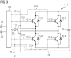
- Figure 3 shows a schematic view of a full-bridge module 1_1 in the modular multilevel converter of Fig. 1 .
- the submodule 1_1 designed as a full-bridge module, has, compared to the half-bridge module, Fig. 2 four electronic switching elements 12.1, 12.2, 12.3, 12.4 and four diodes 13.1, 13.2, 13.3, 13.4. It is characterized by the fact that, with appropriate control of the four electronic switching elements 12.1, 12.2, 12.3, 12.4, between the first submodule connection 11.1 and the second submodule connection 11.2, either the positive voltage of the energy storage device 14, the negative voltage of the energy storage device 14, or a voltage of zero (zero voltage) can be output. Thus, the polarity of the output voltage can be reversed using the full-bridge module.
- the modular multilevel converter 10 from Fig. 1 can have either only half-bridge modules, only full-bridge modules or also half-bridge modules and full-bridge modules.
Landscapes
- Engineering & Computer Science (AREA)
- Power Engineering (AREA)
- Inverter Devices (AREA)
Description
- Die Erfindung betrifft ein Verfahren zum Betreiben eines modularen Multilevel-Umrichters und einen modularen Multilevel-Umrichter.
- Umrichter sind leistungselektronische Schaltungen zum Umwandeln von elektrischer Energie. Mit Umrichtern kann Wechselstrom in Gleichstrom, Gleichstrom in Wechselstrom, Wechselstrom in Wechselstrom anderer Frequenz und/oder Amplitude oder Gleichstrom in Gleichstrom anderer Spannung umgewandelt werden. Umrichter können eine Vielzahl von gleichartigen Submodulen aufweisen, welche elektrisch in Reihe geschaltet sein können. Diese Submodule weisen jeweils mindestens zwei elektronische Schaltelemente und einen elektrischen Energiespeicher auf. Solche Umrichter werden als modulare Multilevel-Umrichter (kurz: MMC oder M2C) bezeichnet.
- Durch die elektrische Reihenschaltung der Submodule lassen sich hohe Ausgangsspannungen erreichen. Die modularen Multilevel-Umrichter sind einfach an unterschiedliche Spannungen anpassbar (skalierbar) und eine gewünschte Ausgangsspannung kann relativ genau erzeugt werden. Modulare Multilevel-Umrichter werden oftmals im Hochspannungsbereich eingesetzt, beispielsweise als Umrichter bei Hochspannungs-Gleichstrom-Übertragungsanlagen (kurz: HGÜ oder HVDC) oder als Blindleistungskompensatoren bei flexiblen Drehstromübertragungssystemen (FACTS).
- Aus der internationalen Patentanmeldung
WO 2017/125134 A1 ist ein modularer Multilevel-Umrichter bekannt, bei dem die Submodule jeweils eine optische Überbrückungseinrichtung aufweisen, welche das jeweilige Submodul bei einem Defekt des Submoduls optisch überbrückt. - Aus der Patentanmeldung
CN 110 635 675 A ist ein Verfahren zum Erkennen von Submodulen bekannt, die nicht mehr von einem Steuerungssystem überwacht werden können. Diese Submodule werden als schwarze Submodule bezeichnet. - Die Patentanmeldung
CN 110 677 029 A offenbart ein Submodul eines modularer Multilevel-Umrichters, das einen passiven Überspannungsschutz aufweist. Dabei sind die Submodulanschlüsse mit einer Parallelschaltung aus einem elektronischen Schalter und einem Bypass-Schalter versehen. - Aus der Patentanmeldung
CN 107 728 508 B ist es bekannt, Submodule eines modularer Multilevel-Umrichters zu erkennen, die nicht in der Lage sind, Statusinformationen zu einer Überwachungseinrichtung zu senden. - In modularen Multilevel-Umrichtern besteht eine Herausforderung unter anderem darin, wie mit defekten Submodulen umgegangen wird.
- In der Regel kann im Fall eines Ausfalls eines einzelnen Submoduls des modularen Multilevel-Umrichters eine Abschaltung der gesamten mit Strom versorgten Anlage nicht akzeptiert werden. Deshalb muss das fehlerhafte Submodul während des Normalbetriebs in einen sicheren Zustand überführt werden und wird erst beim nächsten regulären Herunterfahren der Anlage ausgetauscht.
- Um den Weiterbetrieb auch mit defekten Submodulen zu ermöglichen, können alle Submodule mit einem Bypass-Schalter ausgestattet sein, der das jeweilige Submodul überbrücken kann. Dieser Bypass-Schalter kann zwischen den Submodulanschlüssen (oder auch Anschlussklemmen) des Submoduls installiert sein. So kann der Anlagenstrom über das fehlerhafte Submodul fließen ohne eine Beschädigung des modularen Multilevel-Umrichters, insbesondere durch entstehende Lichtbögen, zu bewirken.
- Ein Kriterium zum Schließen des Bypass-Schalters kann sein, dass das Submodul beim Überschreiten eines Schwellenwertes der Kondensatorspannung eines Kondensators in dem Submodul selbstständig die Schließung des Bypass-Schalters vornimmt (dies kann auch als Bypass-Schalter-Schwelle bezeichnet werden). Dadurch wird das Submodul überbrückt und vor einer weiteren Aufladung geschützt. Die dafür notwendige Logik kann auf dem Submodul installiert sein und autark von der restlichen Ansteuerung des Submoduls arbeiten.
- Durch dieses Auslösekriterium lässt sich ein Großteil der Fehlerfälle beherrschen, da viele Fehlerszenarien direkt, das heißt durch den Fehlereintritt selbst, oder indirekt, das heißt durch eine Reaktion der Umrichter-Steuerung, zum Blockieren des fehlerhaften Submoduls führen können. Wenn das Submodul blockiert ist, werden keine Ansteuersignale mehr an die Schaltelemente des Submoduls gesendet bzw. wird die Leistungselektronik des Submoduls abgeschaltet.
- Ist ein Submodul blockiert, so kann es über Freilaufdioden der elektronischen Schaltelemente des Submoduls nur noch aufgeladen werden. Eine Entladung ist nicht mehr möglich. Wird die Anlage weiterbetrieben, wird das Submodul folglich unweigerlich durch den fließenden Zweigstrom aufgeladen. Das Blockieren eines Submoduls während des Betriebs führt somit zum Schließen des Bypass-Schalters.
- Dieser Selbstschutz der Submodule funktioniert auch bei Ausfall einer Kommunikation zwischen den Submodulen und einer Kommunikationsvorrichtung bzw. Steuervorrichtung des modularen Multilevel-Umrichters. Empfängt das betroffene Submodul nämlich keine Kommunikationstelegramme mehr von der Kommunikationsvorrichtung, so blockiert es sich selbst. Werden in der Umrichter-Steuerung keine Kommunikationstelegramme mehr vom betreffenden Submodul empfangen, so wird ein Befehl zum Blockieren des Submoduls ausgesendet.
- Da der Bypass-Schalter während des Betriebs nicht zu 100 % auf Funktion getestet werden kann, offenbart sich erst im Falle eines Fehlers des Submoduls, ob dieser funktioniert. Das Szenario eines Versagens eines Bypass-Schalters muss folglich berücksichtigt werden. In diesem Fall ist mit einem undefinierten Stromfluss durch das Submodul, also einem Lichtbogen, zu rechnen, welcher die Anlage beschädigen kann. Im Falle eines Versagens des Bypass-Schalters muss folglich die Anlage abgeschaltet werden.
- Zur Sicherstellung, dass der Bypass-Schalter geschlossen ist, kann jedes Submodul eine Überwachung des Bypass-Schalters aufweisen. Für einen Großteil der Fehler von Submodulen erhält die Kommunikationsvorrichtung bzw. Steuervorrichtung somit vom Submodul die Rückmeldung, ob der Bypass-Schalter geschlossen oder offen ist. Im Falle eines Ausfalls der Kommunikation ist dies allerdings nicht mehr möglich. Kommt es folglich zu einem Ausfall der Kommunikation mit einem Submodul und gleichzeitig zum Versagen des Bypass-Schalters kann dies von der Kommunikationsvorrichtung bzw. Steuervorrichtung nicht erkannt werden.
- Wird die Anlage in diesem Fall nicht abgeschaltet, so würde der Anlagenstrom das betreffende Submodul immer weiter laden, bis es an einer Stelle zum Versagen einer Isolation kommen würde. Anschließend würde sich ein Lichtbogen ausbilden und der Anlagenstrom würde undefiniert über diese Fehlerstelle fließen. Selbst wenn ein solcher Lichtbogen von einer optischen Überwachung in einer Umrichterhalle detektiert wird, ist die Folge unweigerlich eine große Beschädigung der Anlage.
- Auch bei geringerem Strom ist damit zu rechnen, dass ein Lichtbogen nach wenigen Sekunden aus dem Submodul austritt und so zu Beschädigungen in der Anlage führt.
- Zur sicheren Handhabung des vorstehend beschriebenen Fehlerszenarios kann die Schließung des Bypass-Schalters nicht nur vom betreffenden Submodul selbst, sondern auch von einem anderen Submodul, etwa einem benachbarten Submodul überwacht werden. Jeweils zwei benachbarte Submodule können so ein Paar bilden, dass sich gegenseitig überwacht. Fällt ein Submodul mit einem Kommunikationsfehler aus, so wird die Schließung des betreffenden Bypass-Schalters von dessen benachbartem Submodul detektiert und an die Kommunikationsvorrichtung bzw. Steuervorrichtung kommuniziert.
- Damit durch eine solche Bypass-Schalter-Schließüberwachung ein Versagen eines Bypass-Schalters sicher detektiert werden kann, muss eine zeitliche Aufladung des fehlerbehafteten, blockierten Submoduls beachtet werden. Erst wenn die Bypass-Schalter-Schwelle überschritten wurde, offenbart sich, ob der Bypass-Schalter im fehlerhaften Submodul funktioniert.
- Ist ein Submodul blockiert und wird vom fließenden Anlagenstrom aufgeladen, so kann es abhängig vom Arbeitspunkt der Anlage gegebenenfalls sehr lange dauern, bis die Kondensatorspannung den Schwellenwert für das Schließen des Bypass-Schalters überschreitet. Befindet sich die Anlage bspw. gerade im Leerlauf oder bei geringer Leistung, kann die Aufladung gegebenenfalls mehrere zehn Sekunden dauern. Ein zu langes Warten für die Aufladung und das damit verbundene Schließen des Bypass-Schalters kann aber nicht in Kauf genommen werden, da nach einer Zeitdauer von wenigen Sekunden mit dem Austreten des Lichtbogens aus dem Submodul gerechnet werden muss. In dieser Zeit muss folglich die Detektion des Versagens eines Bypass-Schalters stattfinden.
- Damit eine Detektion eines Versagens eines Bypass-Schalters auch bei geringer Leistung bzw. im Leerlauf der Anlage im Stand der Technik möglich ist, muss im Betrieb ein minimaler Anlagenstrom sichergestellt werden. Somit ist ein minimal vorhandener Stromfluss über die Submodule vorhanden, wodurch das Erreichen der Bypass-Schalter-Schwelle nach einer gewissen Zeit sichergestellt ist.
- Die vorstehend beschriebene Lösung zur Detektion eines Versagens des Bypass-Schalters benötigt einen minimalen Stromfluss über die Submodule. Dieser Stromfluss verursacht bei geringer Leistung bzw. im Leerlauf signifikante Zusatzverluste, was zur Erhöhung der Betriebskosten der Anlage führt.
- Aufgabe der Erfindung ist es daher, zumindest teilweise die Nachteile aus dem Stand der Technik bekannter Verfahren zum Betreiben von modularen Multilevel-Umrichtern zu vermindern, insbesondere ein Betriebsverfahren bereitzustellen, dass besonders kostengünstig ist und besonders zuverlässig die Detektion eines Versagens eines Bypass-Schalters ermöglicht.
- Die voranstehende Aufgabe wird durch die Gegenstände der Patentansprüche, insbesondere durch ein Verfahren zum Betreiben eines modularen Multilevel-Umrichters nach Anspruch 1 und durch einen modularen Multilevel-Umrichter nach Anspruch 8 gelöst. Weitere Vorteile und Details der Erfindung ergeben sich aus den Unteransprüchen, der Beschreibung und den Zeichnungen. Dabei gelten Merkmale und Details, die im Zusammenhang mit dem erfindungsgemäßen Verfahren offenbart sind, selbstverständlich auch im Zusammenhang mit dem erfindungsgemäßen modularen Multilevel-Umrichter, sodass bezüglich der Offenbarung zu den einzelnen Erfindungsaspekten stets wechselseitig Bezug genommen wird beziehungsweise werden kann. Die gestellte Aufgabe wird gemäß einem ersten Aspekt gelöst durch ein Verfahren zum Betreiben eines modularen Multilevel-Umrichters mit einer Vielzahl von Submodulen, welche jeweils zumindest zwei elektronische Schaltelemente, einen elektrischen Energiespeicher, zwei Submodulanschlüsse, einen Bypass-Schalter zur Überbrückung seines Submoduls (1, 2, 3, 4, 5, 6) in dem modularen Multilevel-Umrichter und ein Kommunikationselement zur Kommunikation mit einer Kommunikationsvorrichtung des modularen Multilevel-Umrichters aufweisen, wobei das Verfahren die Schritte aufweist:
- (a) Ermitteln, dass die Vielzahl von Submodulen ein derart defektes Submodul aufweist, dass das Kommunikationselement in dem defekten Submodul nicht mit der Kommunikationsvorrichtung kommuniziert,
- (b) Bestimmen, ob ein aktueller aus einem Arbeitspunkt des modularen Multilevel-Umrichters resultierender Armstrom unterhalb eines vorbestimmten Schwellenwertes liegt, und
- (c) Erzeugen oder Verstärken eines internen Kreisstromes in dem modularen Multilevel-Umrichter mit dem defekten Submodul, falls der aus dem Arbeitspunkt des modularen Multilevel-Umrichters resultierende Armstrom unterhalb des vorbestimmten Schwellenwertes des Arbeitspunktes liegt.
- Folglich sieht die bereitgestellte Lösung vor, dass im Bedarfsfall ein Umrichter-interner Kreisstrom erzeugt wird. Hierdurch können die Verluste im Leerlauf deutlich reduziert werden. Ferner können im Bedarfsfall Kreisströme erzeugt werden, die wesentlich größer sind als die bisherigen minimalen Anlagenströme bzw. Umrichterströme oder Ströme im modularen Multilevel-Umrichter. Ein defektes Submodul kann somit mittels des bereitgestellten Verfahrens wesentlich schneller geladen werden, wodurch das Versagen eines Bypass-Schalters schneller detektierbar wird und die Wahrscheinlichkeit einer Fehlerausprägung mit Lichtbogen wesentlich reduziert wird.
- Der Arbeitspunkt und der daraus resultierende Armstrom können mittels der Wirkleistung und Blindleistung gegenüber einer Gleichspannungsseite bzw. einem Wechselspannungsnetz des modularen Multilevel-Umrichters bestimmt werden. Der Armstrom ist der Strom, der durch einen Phasenmodulzweig eines Phasenmoduls des modularen Multilevel-Umrichters fließt. Dieser Armstrom setzt sich aus einer Gleichstromkomponente und einer Wechselstromkomponente zusammen. Die Gleichstromkomponente des Armstromes hängt vom Wirkleistungsaustausch mit der Gleichspannungsseite ab. Die Wechselstromkomponente hängt vom Leistungsaustausch (Wirk- und Blindleistung) mit der Wechselspannungsseite ab. In dem Phasenmodulzweig sind mehrere Submodule in Reihe zueinander geschaltet. Die Phasenmodulzweige sind jeweils an einer Wechselspannungsseite und einer Gleichspannungsseite angeschlossen. Je zwei Phasenmodulzweige bilden dabei ein Phasenmodul. Entsprechend wird der Schwellenwert durch eine Höhe oder Amplitude einer minimalen Stromstärke des durch den modularen Multilevel-Umrichter fließenden Armstromes bestimmt. Der Schwellenwert kann derart gewählt werden, dass der Armstrom ausreicht, um den elektrischen Energiespeicher in einem blockierten Submodul in einer kurzen Zeitspanne zu laden, sodass der Bypass-Schalter dieses Submoduls in der kurzen Zeitspanne geschlossen wird.
- Die elektronischen Schaltelemente der Submodule können als abschaltbare Halbleiterventile, insbesondere als Transistoren, ganz besonders als Bipolartransistoren mit isolierter Gate-Elektrode, ausgebildet sein. Antiparallel zu jedem der elektronischen Schaltelemente kann jeweils eine Halbleiterdiode, insbesondere eine Freilaufdiode, geschaltet sein.
- Die elektrischen Energiespeicher der Submodule können als Kondensatoren ausgebildet sein.
- Die Bypass-Schalter der Submodule können insbesondere zwischen den zwei Submodulanschlüssen des jeweiligen Submodules angeordnet sein. Die Submodulanschlüsse können als Klemmanschlüsse ausgebildet sein.
- Submodule der Vielzahl von Submodulen können mittels der Submodulanschlüsse in Reihe miteinander geschaltet sein. Mehrere in Reihe miteinander geschaltete Submodule können zu einem Phasenmodulzweig zusammengefasst sein. Je zwei miteinander verschaltete Phasenmodulzweige können zu einem Phasenmodul zusammengefasst sein.
- Der interne Kreisstrom fließt in dem defekten Submodul. Der interne Kreisstrom kann insbesondere zusätzlich zu einem bei einem Arbeitspunkt des modularen Multilevel-Umrichters fließenden Stromes, insbesondere Drehstromes, injiziert bzw. erzeugt oder verstärkt werden. Ferner kann der Umrichter-interne Kreisstrom erzeugt oder verstärkt werden, wenn sich der modulare Multilevel-Umrichter in einem Leerlaufbetrieb befindet. Bei internen bzw. Umrichter-internen Kreisströmen handelt es sich um einen Stromfluss zwischen Phasenmodulen, insbesondere den drei Phasenmodulen, des modularen Multilevel-Umrichters, der zu keinem Leistungsaustausch mit einer Wechselspannungs- oder einer Gleichspannungsseite des modularen Multilevel-Umrichters führt.
- Es ist vorgesehen, dass das defekte Submodul vor dem Erzeugen oder Verstärken des internen Kreisstromes in dem modularen Multilevel-Umrichter mit dem defekten Submodul blockiert wird, wodurch der elektrische Energiespeicher des defekten Submoduls mittels des internen Kreisstromes aufgeladen wird. Beim Blockieren des defekten Submoduls werden die elektronischen Schaltelemente nicht mehr angesteuert bzw. wird eine Leistungselektronik des Submoduls ausgeschaltet. Folglich fließen der Strom des modularen Multilevel-Umrichters gemäß seinem Arbeitspunkt und/oder der Umrichter-interne Kreisstrom durch das defekte Submodul, insbesondere über die Freilaufdioden, zu dem elektrischen Energiespeicher und laden diesen auf. Das Blockieren kann dabei direkt über den Eintritt des Defektes des Submoduls selbst oder indirekt durch eine Reaktion einer Steuerungsvorrichtung des modularen Multilevel-Umrichters ausgelöst werden.
- Dabei ist zudem vorgesehen, dass der Bypass-Schalter des blockierten defekten Submoduls geschlossen wird, um das blockierte defekte Submodul in dem modularen Multilevel-Umrichter zu überbrücken, wenn der elektrische Energiespeicher des blockierten defekten Submoduls mittels des internen Kreisstromes eine vorbestimmte Aufladung erreicht hat. Die vorbestimmte Aufladung des elektrischen Energiespeichers kann eine maximale Aufladung des elektrischen Energiespeichers sein bzw. der maximalen Spannung des elektrischen Energiespeichers entsprechen. Folglich gilt dies als einfaches Auslösekriterium, um den Bypass-Schalter zu schließen, wenn ein defektes Submodul blockiert ist.
- Es kann vorgesehen sein, dass bei der Bestimmung, ob der aus dem Arbeitspunkt resultierende Armstrom des modularen Multilevel-Umrichters unterhalb des vorbestimmten Schwellenwertes des Arbeitspunktes liegt, beispielsweise ein äquivalenter Ladestrom des elektrischen Energiespeichers in dem defekten Submodul herangezogen wird. Mittels des äquivalenten Ladestromes lässt sich eine Aussage darüber treffen, wie viel von dem beim Arbeitspunkt fließenden Armstrom bei dem elektrischen Energiespeicher als äquivalenter Ladestrom ankommt, wenn das Submodul blockiert ist. Der äquivalente Ladestrom kann näherungsweise bestimmt werden.
- Beim einem modularen Multilevel-Umrichtern mit Halbbrückenmodulen als Submodulen kann der äquivalente DC-Ladestrom iDC_BPS durch folgende Formel näherungsweise bestimmt werden:

- Beim einem modularen Multilevel-Umrichter mit Vollbrückenmodulen als Submodulen kann der äquivalente DC-Ladestrom iDC_BPS durch folgende Formel näherungsweise bestimmt werden:

- Alternativ oder zusätzlich kann der aus dem Arbeitspunkt des modularen Multilevel-Umrichters resultierende Armstrom in einer Lookup-Tabelle nachgeschlagen werden, um zu bestimmen, ob der aus dem Arbeitspunkt resultierende Armstrom des modularen Multilevel-Umrichters unterhalb des vorbestimmten Schwellenwertes des Armstromes liegt und insbesondere um die Höhe, Frequenz und/oder Phasenlage des internen Kreisstromes zu bestimmen. In der Lookup-Tabelle kann hierzu für jeden aus dem Arbeitspunkt des modularen Multilevel-Umrichters resultierender Armstrom (insbesondere anhand des P-Q-Diagramms) eine Höhe, Frequenz und/oder Phasenlage des internen Kreisstromes hinterlegt sein.
- Es ist vorgesehen, dass jedes Submodul der Vielzahl von Submodulen mittels je eines Kommunikationselements mit einem Bypass-Schalter eines anderen Submoduls der Vielzahl von Submodulen kommunikationstechnisch verbunden ist, um jeweils den Zustand eines Bypass-Schalters jedes Submoduls der Vielzahl von Submodulen mittels jeweils eines anderen Submoduls zu überwachen, wobei das Erzeugen oder Verstärken des Kreisstromes in dem modularen Multilevel-Umrichter mit dem defekten Submodul erfolgt, falls ferner das Kommunikationselement eines das defekte Submodul überwachenden Submoduls, das mit dem Bypass-Schalter des defekten Submoduls kommunikationstechnisch verbunden ist, mit der Kommunikationsvorrichtung kommuniziert. Der Zustand des Bypass-Schalters kann entsprechend offen oder geschlossen sein. Im offenen Zustand des Bypass-Schalters wird das defekte Submodul mit Strom durchflossen. Im geschlossenen Zustand des Bypass-Schalters ist das defekte Submodul überbrückt. Die kommunikationstechnischen Verbindungen können beispielsweise mittels Lichtwellenleitern ausgebildet sein. Insbesondere können Submodule in einem Paar von Submodulen sich gegenseitig überwachen. Folglich kann ein Submodul des Paars mittels eines Kommunikationselementes mit dem Bypass-Schalter des anderen Submoduls des Paars und umgekehrt verschaltet sein. Die Submodule des Paars von Submodulen können benachbarte Submodule sein, um die Kommunikationswege zu verkürzen.
- Es ist ferner vorgesehen, dass das Erzeugen oder Verstärken des internen Kreisstromes in dem modularen Multilevel-Umrichter mit dem defekten Submodul erfolgt, falls ferner das Kommunikationselement des das defekte Submodul überwachenden Submoduls an die Kommunikationsvorrichtung kommuniziert, dass der Bypass-Schalter des defekten Submoduls offen ist. Dann steht noch nicht fest, ob der Bypass-Schalter funktionsfähig ist oder nicht, da der elektrische Energiespeicher womöglich noch nicht hinreichend geladen ist, um den Bypass-Schalter zu schließen. Um nun schnellstmöglich den Bypass-Schalter zu schließen und Sicherheit darüber zu schaffen, ob der Bypass-Schalter funktionsfähig ist, muss der Umrichter-interne Kreisstrom erzeugt oder verstärkt werden, falls der aus dem Arbeitspunkt des modularen Multilevel-Umrichters resultierende Armstrom unterhalb des vorgegebenen Schwellenwertes liegt.
- Ferner ist dabei auch bevorzugt, dass nach einer vorgegebenen Zeitdauer des Fließens des erzeugten oder verstärkten internen Kreisstromes in dem modularen Multilevel-Umrichter mit dem defekten Submodul mittels des das defekte Submodul überwachenden Submoduls geprüft wird, ob der Bypass-Schalter in dem defekten Submodul geschlossen ist. Nach der vorgegebenen Zeitdauer des Fließens des internen Kreisstromes müsste der Bypass-Schalter nämlich geschlossen sein. Ist dies der Fall, hat der Bypass-Schalter funktioniert, sodass das defekte Submodul überbrückt wurde und bei dem nächsten Stillstand oder der nächsten Wartung ausgetauscht werden kann.
- Dabei ist wiederum bevorzugt, dass die vorgegebene Zeitdauer in Abhängigkeit von der Stromstärke und/oder der Spannung des erzeugten oder verstärkten internen Kreisstromes eingestellt wird. Die Zeitdauer kann insoweit abhängig von der Stromstärke und/oder der Spannung zur Optimierung von Stromverbrauch, Sicherheit und Zuverlässigkeit gewählt werden.
- Auch ist dabei bevorzugt, dass der modulare Multilevel-Umrichter mit dem defekten Submodul ausgeschaltet wird, falls das das defekte Submodul überwachende Submodul nach Ablauf der vorgegebenen Zeitdauer mittels seines Kommunikationselementes an die Kommunikationsvorrichtung kommuniziert, dass der Bypass-Schalter des defekten Submoduls offen ist. Ist der Bypass-Schalter nämlich weiterhin offen, lässt dies darauf schließen, dass der Bypass-Schalter defekt ist, sodass nun das Herunterfahren des modularen Multilevel-Umrichters eingeleitet werden muss, um eine ansonsten mögliche Beschädigung zu vermeiden.
- Im Übrigen ist bevorzugt, dass eine Höhe, Frequenz und/oder Phasenlage des internen Kreisstromes in dem modularen Multilevel-Umrichter mit dem defekten Submodul in Abhängigkeit von dem aus dem Arbeitspunkt des modularen Multilevel-Umrichters resultierenden Armstroms eingestellt wird. Hierzu kann die zuvor erwähnte Lookup-Tabelle genutzt werden. Folglich kann der Energieverbrauch des modularen Multilevel-Umrichters durch Einstellen der Freiheitsgrade Höhe, Frequenz und/oder Phasenlage des internen Kreisstromes optimiert werden. Läuft der modulare Multilevel-Umrichter beispielsweise in einem Leerlaufbetrieb, wird ein hoher interner Kreisstrom erzeugt. Läuft der modulare Multilevel-Umrichter hingegen beispielsweise mit einer Teillast unterhalb des vorbestimmten Schwellenwertes für den Armstrom, wird ein demgegenüber geringerer interner Kreisstrom erzeugt, da der insgesamt fließende Strom dann dennoch so hinreichend hoch ist, dass mit ähnlicher oder gleicher Sicherheit eine Beschädigung des modularen Multilevel-Umrichters verhindert werden kann.
- Dabei ist bevorzugt, dass der Schwellenwert (des Armstroms) derart vorbestimmt ist oder wird, dass ein Schließen des Bypass-Schalters in dem blockierten defekten Submodul bei Betreiben des modularen Multilevel-Umrichters bei dem Schwellenwert höchstens 10 Sekunden, insbesondere höchstens 7 Sekunden, dauert. Dadurch wird ermöglicht, dass die Feststellung eines Defektes des Bypass-Schalters erfolgt, noch bevor es üblicherweise zu einer Bildung eines Lichtbogens in dem defekten Submodul kommt, die zu einer Beschädigung des modularen Multilevel-Umrichters führen würde.
- Auch ist bevorzugt, dass die Submodule als Halbbrückenmodule und/oder als Vollbrückenmodule ausgebildet sind. Dabei ist es möglich, dass der modulare Multilevel-Umrichter nur Halbbrückenmodule, nur Vollbrückenmodule oder sowohl Halbbrückenmodule als auch Vollbrückenmodule aufweist.
- Die eingangs gestellte Aufgabe wird gemäß einem zweiten Aspekt gelöst durch einen modularen Multilevel-Umrichter gemäß den Merkmalen des ersten Aspektes der Erfindung, wobei der modulare Multilevel-Umrichter zum Ausführen des Verfahrens gemäß dem ersten Aspekt der Erfindung eingerichtet ist.
- Entsprechend weist der modularen Multilevel-Umrichter eine Vielzahl von Submodulen, welche jeweils zumindest zwei elektronische Schaltelemente, einen elektrischen Energiespeicher, zwei Submodulanschlüsse, einen Bypass-Schalter zu seiner Überbrückung in dem modularen Multilevel-Umrichter und ein Kommunikationselement zur Kommunikation mit einer Kommunikationsvorrichtung des modularen Multilevel-Umrichters aufweisen, auf.
- Insbesondere kann der modulare Multilevel-Umrichter ferner eine Steuervorrichtung aufweisen. Die Steuervorrichtung kann die Kommunikationsvorrichtung aufweisen oder kommunikationstechnisch mit dieser verbunden sein. Die Steuervorrichtung kann zur Ausführung der Operationen des modularen Multilevel-Umrichters eingerichtet sein, also beispielsweise des Einstellens des Arbeitspunktes des modularen Multilevel-Umrichters, eines Abschaltens des modularen Multilevel-Umrichters, aber auch eines Blockierens eines defekten Submodules und eines Erzeugens oder Verstärkens des internen Kreisstromes in dem modularen Multilevel-Umrichter. Folglich kann insbesondere die Steuervorrichtung zum Ausführen des Verfahrens gemäß dem ersten Aspekt der Erfindung eingerichtet sein.
- Weitere, die Erfindung verbessernde Maßnahmen ergeben sich aus der nachfolgenden Beschreibung zu verschiedenen Ausführungsbeispielen der Erfindung, welche in den Figuren schematisch dargestellt sind. Sämtliche aus den Ansprüchen, der Beschreibung oder den Figuren hervorgehende Merkmale und/oder Vorteile, einschließlich konstruktiver Einzelheiten und räumlicher Anordnungen können sowohl für sich als auch in den verschiedenen Kombinationen erfindungswesentlich sein.
- Anhand der beigefügten Zeichnungen wird die Erfindung nachfolgend näher erläutert. Dabei zeigt:
- Figur 1
- eine schematische Ansicht eines Schaltbildes eines modularen Multilevel-Umrichters gemäß einem Ausführungsbeispiel der Erfindung,
- Figur 2
- eine schematische Ansicht eines Halbbrückenmoduls in dem modularen Multilevel-Umrichter aus
Figur 1 , und - Figur 3
- eine schematische Ansicht eines Vollbrückenmoduls in dem modularen Multilevel-Umrichter aus
Figur 1 . - Elemente mit gleicher Funktion und Wirkungsweise sind in den
Figuren 1 bis 3 jeweils mit denselben Bezugszeichen versehen. Mehrere gleiche Elemente in einer Figur sind mit einer fortlaufenden Nummerierung versehen, wobei die fortlaufende Nummerierung durch einen Punkt oder Unterstrich von ihrem Bezugszeichen getrennt ist. -
Figur 1 zeigt eine schematische Ansicht eines Schaltbildes eines modularen Multilevel-Umrichters 10 gemäß einem Ausführungsbeispiel der Erfindung. - Der modulare Multilevel-Umrichter 1 weist einen ersten Wechselspannungsanschluss 7, einen zweiten Wechselspannungsanschluss 8 und einen dritten Wechselspannungsanschluss 9 auf. Der erste Wechselspannungsanschluss 7 ist elektrisch mit einem ersten Phasenmodulzweig 41 und einem zweiten Phasenmodulzweig 42 verbunden. Der erste Phasenmodulzweig 41 und der zweite Phasenmodulzweig 42 bilden ein erstes Phasenmodul 51 des modularen Multilevel-Umrichters 10.
- Das dem ersten Wechselspannungsanschluss 7 abgewandte Ende des ersten Phasenmodulzweigs 41 ist mit einem ersten Gleichspannungsanschluss 47 elektrisch verbunden. Das dem ersten Wechselspannungsanschluss 7 abgewandte Ende des zweiten Phasenmodulzweigs 42 ist mit einem zweiten Gleichspannungsanschluss 48 elektrisch verbunden. Der erste Gleichspannungsanschluss 47 ist ein positiver Gleichspannungsanschluss und der zweite Gleichspannungsanschluss 48 ist ein negativer Gleichspannungsanschluss.
- Der zweite Wechselspannungsanschluss 8 ist mit einem Ende eines dritten Phasenmodulzweigs 43 und mit einem Ende eines vierten Phasenmodulzweigs 44 elektrisch verbunden. Der dritte Phasenmodulzweig 43 und der vierte Phasenmodulzweig 44 bilden ein zweites Phasenmodul 52.
- Der dritte Wechselspannungsanschluss 9 ist mit einem Ende eines fünften Phasenmodulzweigs 45 und mit einem Ende eines sechsten Phasenmodulzweigs 46 elektrisch verbunden. Der fünfte Phasenmodulzweig 45 und der sechste Phasenmodulzweig 46 bilden ein drittes Phasenmodul 53.
- Das dem zweiten Wechselspannungsanschluss 8 abgewandte Ende des dritten Phasenmodulzweigs 43 und das dem dritten Wechselspannungsanschluss 9 abgewandte Ende des fünften Phasenmodulzweigs 45 sind mit dem ersten Gleichspannungsanschluss 47 elektrisch verbunden. Das dem zweiten Wechselspannungsanschluss 8 abgewandte Ende des vierten Phasenmodulzweigs 44 und das dem dritten Wechselspannungsanschluss 9 abgewandte Ende des sechsten Phasenmodulzweigs 46 sind mit dem zweiten Gleichspannungsanschluss 48 elektrisch verbunden.
- Jeder Phasenmodulzweig 41, 42, 43, 44, 45, 46 weist eine Mehrzahl von Submodulen (1 1, 1_2, 1_3, ... 1_n; 2 1 ... 2_n, usw.) auf, welche, insbesondere mittels ihrer Submodulanschlüsse 11.1, 11.2 (siehe
Fig. 2 und3 ), elektrisch in Reihe geschaltet sind. In jedem der Phasenmodulzweige 41, 42, 43, 44, 45, 46 fließt ein aus dem Arbeitspunkt des modularen Multilevel-Umrichters 1 resultierender Armstrom. Der Arbeitspunkt und der daraus resultierende Armstrom werden aus der Wirkleistung und der Blindleistung gegenüber den Gleichspannungsanschlüssen 47, 48 und den Wechselspannungsanschlüssen 7, 8, 9 des modularen Multilevel-Umrichters 1 bestimmt. - In diesem Ausführungsbeispiel weist jeder Phasenmodulzweig 41, 42, 43, 44, 45, 46 n Submodule 1_1 bis 6_n auf. Die Anzahl der elektrisch in Reihe geschalteten Submodule 1_1 bis 6_n kann unterschiedlich sein, mindestens sind zwei Submodule 1_1 bis 6_n in Reihe geschaltet, es können aber auch beispielsweise zumindest 50 oder zumindest 100 Submodule 1_1 bis 6_n elektrisch in Reihe geschaltet sein. In diesem Ausführungsbeispiel ist n = 36. Der erste Phasenmodulzweig 41 weist also 36 Submodule 1_1, 1_2, 1_3, ... 1_36 auf.
- Im linken Bereich der
Fig. 1 ist schematisch eine Kommunikationsvorrichtung 30 des modularen Multilevel-Umrichters 10 für die Submodule 1_1 bis 6_n dargestellt. Die Kommunikationsvorrichtung 30 kann auch als Steuervorrichtung ausgebildet sein oder eine Steuervorrichtung kann die Kommunikationsvorrichtung 30 umfassen. Von der Kommunikationsvorrichtung 30 werden optische Nachrichten zu den einzelnen Submodulen 1_1 bis 6_n übertragen. - Die Nachrichtenübertragung zwischen der Steuervorrichtung 30 und einem Submodul 1_1 bis 6_n ist jeweils durch eine gestrichelte Linie 33 dargestellt, wobei die Richtung der Nachrichtenübertragung durch die Pfeilspitze an den gestrichelten Linien 33 symbolisiert wird. Vorliegend erfolgt die Kommunikation durch erste Lichtwellenleiter 33.1, 33.12, 33.3, 33.4, 33.5, 33.6, die mittels der gestrichelten Linien gezeigt sind. Die Kommunikationsvorrichtung 30 sendet mittels zweiter Kommunikationsausgänge 31.1, 31.2, 31.3, vorliegend optischer Ausgänge, optische Nachrichten an die Submodule 1_1 bis 6_n ab und empfängt optische Nachrichten von den einzelnen Submodulen mittels zweiter Kommunikationseingänge 32.1, 32.2, 32.3, vorliegend optischer Eingänge. Dies ist am Beispiel der Submodule 1_1, l_n und 4_3 dargestellt; zu den anderen der Submodule 1_1 bis 6_n werden auf die gleiche Art und Weise optische Nachrichten gesendet bzw. von diesen Submodulen 1_1 bis 6_n empfangen.
-
Figur 2 zeigt eine schematische Ansicht eines als Halbbrückenmodul ausgebildeten Submoduls 1_1 in dem modularen Multilevel-Umrichter ausFig. 1 . - Dabei kann es sich beispielsweise um das Submodul 1_1 des ersten Phasenmodulzweigs 41 (oder auch um eines der anderen in
Fig. 1 dargestellten Submodule) handeln. Das Submodul 1_1 ist als ein Halbbrückenmodul 1_1 ausgestaltet. Das Submodul 1_1 weist ein erstes elektronisches Schaltelement 12.1 in Form eines abschaltbaren Halbleiterventils mit einer ersten antiparallel geschalteten Diode 13.1 auf. Weiterhin weist das Submodul 1_1 ein zweites elektronisches Schaltelement 12.2 in Form eines abschaltbaren Halbleiterventils mit einer zweiten antiparallel geschalteten Diode 13.2 sowie einen elektrischen Energiespeicher 14 in Form eines Kondensators auf. Die elektronischen Schaltelemente 12.1, 12.2 sind jeweils als Bipolartransistoren mit isolierter Gate-Elektrode ausgebildet. - Das erste elektronische Schaltelement 12.1 ist elektrisch mit dem zweiten elektronischen Schaltelement 12.2 in Reihe geschaltet. An einem Verbindungspunkt zwischen den beiden elektronischen Schaltelementen 12.1, 12.2 ist ein erster Submodulanschluss 11.1 angeordnet. An dem Anschluss des zweiten elektronischen Schaltelements 12.2, welcher diesem Verbindungspunkt gegenüberliegt, ist ein zweiter Submodulanschluss 11.2 angeordnet. Der zweite Submodulanschluss 11.2 ist weiterhin mit einem ersten Anschluss des elektrischen Energiespeichers 14 verbunden. Ein zweiter Anschluss des Energiespeichers 14 ist elektrisch mit dem Anschluss des ersten Submodulanschlusses 12.1, der dem Verbindungspunkt gegenüberliegt, verbunden.
- Der Energiespeicher 14 ist somit elektrisch parallel geschaltet zu der Reihenschaltung der elektronischen Schaltelemente 12.1, 12.2. Durch entsprechende Ansteuerung der elektronischen Schaltelemente 12.1, 12.2 durch eine nicht gezeigte Ansteuerschaltung mit submodulinternem Kommunikationselement 20 kann erreicht werden, dass zwischen dem ersten Submodulanschluss 11.1 und dem zweiten Submodulanschluss 11.2 entweder die Spannung des Energiespeichers 14 ausgegeben wird oder keine Spannung ausgegeben wird (das heißt eine Nullspannung ausgegeben wird). Durch Zusammenwirken der Submodule der einzelnen Phasenmodulzweige 41, 42, 43, 44, 45, 46 kann so eine jeweils gewünschte Ausgangsspannung des modularen Multilevel-Umrichters 10 erzeugt werden.
- Zwischen den Submodulanschlüssen 11.1, 11.2 ist ein Bypass-Schalter 15 angeordnet. Wenn der Bypass-Schalter 15 geschlossen wird, fließt der Strom über den geschlossenen Bypass-Schalter 15 anstatt zu den elektronischen Schaltelementen 12.1, 12.2 und dem elektrischen Energiespeicher 14.
- Zur submodulexternen Kommunikation weist das Submodul 1_1 einen ersten Kommunikationseingang 21, vorliegend ein optischer Eingang, und einen ersten Kommunikationsausgang 22, vorliegend ein optischer Ausgang, auf. Das Kommunikationselement 20 ist mit dem ersten Kommunikationseingang 21 und dem ersten Kommunikationsausgang 22 verbunden. An den ersten Kommunikationseingang 21 und den zweiten Kommunikationsausgang 22 werden zur submodulexternen Kommunikation jeweils erste Lichtwellenleiter 33.1, 33.2 angeschlossen, die jeweils mit einem der zweiten Kommunikationsausgänge 31 und der zweiten Kommunikationseingängen 32 verbunden werden. Dadurch kann die Ansteuerschaltung bzw. das Kommunikationselement 20 Zustände des Submoduls 1_1 erfassen und an die Kommunikationsvorrichtung 30 melden.
- Der erste Kommunikationseingang 21 des Submoduls 1_1 leitet die an ihm eintreffenden Nachrichten zu dem Kommunikationselement 20 weiter. Das Kommunikationselement 20 gibt (veränderte oder unveränderte) Nachrichten an dem ersten Kommunikationsausgang 22 des Submoduls 1_1 aus.
- Ferner sind die elektronischen Schaltelemente 12.1, 12.2 mittels zweiter Lichtwellenleiter 23.1, 23.1 mit dem Kommunikationselement 20 verbunden, um beispielsweise der Kommunikationsvorrichtung 30 einen Status über die elektronischen Schaltelemente 12.1, 12.2 (blockiert oder nicht blockiert) zu übermitteln oder von der Kommunikationsvorrichtung 30 eine Nachricht zu empfangen, dass die elektronischen Schaltelemente 12.1, 12.2 blockiert werden sollen.
- Das Submodul 1_1 ist mittels des dritten Lichtwellenleiters 24 mit dem elektrischen Energiespeicher 14 kommunikationstechnisch verbunden. Dadurch kann die Ansteuerschaltung bzw. das Kommunikationselement 20 den Ladezustand des elektrischen Energiespeichers 14 erfassen und an die Kommunikationsvorrichtung 30 melden.
- Darüber hinaus ist der Bypass-Schalter 15 mittels eines vierten Lichtwellenleiters 25 mit dem Kommunikationselement 20 verbunden. Dadurch kann das Kommunikationselement 20 den Zustand des Bypass-Schalters 15, also ob dieser geschlossen oder offen ist, ändern und/oder abfragen. Insbesondere kann der Bypass-Schalter 15 geschlossen werden, wenn das Submodul 1_1 blockiert ist und der elektrische Energiespeicher 14 voll aufgeladen ist.
- Zudem führt ein fünfter Lichtwellenleiter 26 von dem Bypass-Schalter 15 nach außerhalb des Submoduls 1_1 weg. Dieser fünfte Lichtwellenleiter 26 führt zu einem Kommunikationselement 20 eines zu dem Submodul 1_1 benachbarten Submoduls 1_2. Mittels des benachbarten Submoduls 1_2 kann dadurch geprüft werden, ob der Bypass-Schalter 15 geschlossen ist oder nicht, selbst wenn eine Kommunikation der Kommunikationsvorrichtung 30 mit dem Kommunikationselement 20 des Submoduls 1_1 ausfällt, soweit die Kommunikation der Kommunikationsvorrichtung 30 mit dem Kommunikationselement 20 des benachbarten Submoduls 1_2 funktioniert.
-
Figur 3 zeigt eine schematische Ansicht eines Vollbrückenmoduls 1_1 in dem modularen Multilevel-Umrichter ausFig. 1 . - Das als Vollbrückenmodul ausgebildete Submodul 1_1 weist gegenüber dem Halbbrückenmodul aus
Fig. 2 vier elektronische Schaltelemente 12.1, 12.2, 12.3, 12.4 sowie vier Dioden 13.1, 13.2, 13.3, 13.4 auf. Es zeichnet sich dadurch aus, dass bei entsprechender Ansteuerung der vier elektronischen Schaltelemente 12.1, 12.2, 12.3, 12.4 zwischen dem ersten Submodulanschluss 11.1 und dem zweiten Submodulanschluss 11.2 wahlweise entweder die positive Spannung des Energiespeichers 14, die negative Spannung des Energiespeichers 14 oder eine Spannung des Wertes Null (Nullspannung) ausgegeben werden kann. Somit kann also mittels des Vollbrückenmoduls die Polarität der Ausgangsspannung umgekehrt werden. Der modulare Multilevel-Umrichter 10 ausFig. 1 kann entweder nur Halbbrückenmodule, nur Vollbrückenmodule oder auch Halbbrückenmodule und Vollbrückenmodule aufweisen. -
- 1
- erstes Submodul
- 2
- zweites Submodul
- 3
- drittes Submodul
- 4
- viertes Submodul
- 5
- fünftes Submodul
- 6
- sechstes Submodul
- 7
- erster Wechselspannungsanschluss
- 8
- zweiter Wechselspannungsanschluss
- 9
- dritter Wechselspannungsanschluss
- 10
- modularer Multilevel-Umrichter
- 11
- Submodulanschluss
- 12
- elektronisches Schaltelement
- 13
- Diode
- 14
- elektrischer Energiespeicher
- 15
- Bypass-Schalter
- 20
- Kommunikationselement
- 21
- erster Kommunikationseingang
- 22
- erster Kommunikationsausgang
- 23
- zweiter Lichtwellenleiter
- 24
- dritter Lichtwellenleiter
- 25
- vierter Lichtwellenleiter
- 26
- fünfter Lichtwellenleiter
- 30
- Kommunikationsvorrichtung
- 31
- zweiter Kommunikationsausgang
- 32
- zweiter Kommunikationseingang
- 33
- erster Lichtwellenleiter
- 41
- erster Phasenmodulzweig
- 42
- zweiter Phasenmodulzweig
- 43
- dritter Phasenmodulzweig
- 44
- vierter Phasenmodulzweig
- 45
- fünfter Phasenmodulzweig
- 46
- sechster Phasenmodulzweig
- 47
- erster Gleichspannungsanschluss
- 48
- zweiter Gleichspannungsanschluss
- 51
- erstes Phasenmodul
- 52
- zweites Phasenmodul
- 53
- drittes Phasenmodul
Claims (8)
- Verfahren zum Betreiben eines modularen Multilevel-Umrichters (10) mit einer Vielzahl von Submodulen (1, 2, 3, 4, 5, 6), welche jeweils zumindest zwei elektronische Schaltelemente (12), einen elektrischen Energiespeicher (14), zwei Submodulanschlüsse (11), einen Bypass-Schalter (15) zur Überbrückung seines Submoduls (1, 2, 3, 4, 5, 6) in dem modularen Multilevel-Umrichter (10) und ein Kommunikationselement (20) zur Kommunikation mit einer Kommunikationsvorrichtung (30) des modularen Multilevel-Umrichters (10) aufweisen, wobei das Verfahren die Schritte aufweist:(a) Ermitteln, dass die Vielzahl von Submodulen (1, 2, 3, 4, 5, 6) ein derart defektes Submodul (1, 2, 3, 4, 5, 6) aufweist, dass das Kommunikationselement (20) in dem defekten Submodul (1, 2, 3, 4, 5, 6) nicht mit der Kommunikationsvorrichtung (30) kommuniziert,
gekennzeichnet durch(b) Bestimmen, ob ein aktueller aus einem Arbeitspunkt des modularen Multilevel-Umrichters (10) resultierender Armstrom unterhalb eines vorbestimmten Schwellenwertes liegt,(c) Erzeugen oder Verstärken eines internen Kreisstromes in dem modularen Multilevel-Umrichter (10) mit dem defekten Submodul (1, 2, 3, 4, 5, 6), falls der aus dem Arbeitspunkt des modularen Multilevel-Umrichters (10) resultierende Armstrom unterhalb des vorbestimmten Schwellenwertes liegt, wobei der interne Kreisstrom über den elektrischen Energiespeicher (14) des defekten Submoduls (1, 2, 3, 4, 5, 6) fließt, wobei das defekte Submodul (1, 2, 3, 4, 5, 6) vor dem Erzeugen oder Verstärken des internen Kreisstromes in dem modularen Multilevel-Umrichter (10) blockiert wird, wodurch der elektrische Energiespeicher (14) in dem defekten Submodul (1, 2, 3, 4, 5, 6) mittels des internen Kreisstromes aufgeladen wird, und wobei der Bypass-Schalter (15) des blockierten defekten Submoduls (1, 2, 3, 4, 5, 6) geschlossen wird, um das blockierte defekte Submodul (1, 2, 3, 4, 5, 6) in dem modularen Multilevel-Umrichter (10) zu überbrücken, wenn der elektrische Energiespeicher (14) des blockierten defekten Submoduls (1, 2, 3, 4, 5, 6) mittels des internen Kreisstromes eine vorbestimmte Aufladung erreicht hat, und(d) Überwachen einer Schließung des Bypass-Schalters nicht nur von dem betreffenden Submodul selbst, sondern auch von einem anderen Submodul, insbesondere von einem benachbarten Submodul, wobei jedes Submodul (1, 2, 3, 4, 5, 6) der Vielzahl von Submodulen (1, 2, 3, 4, 5, 6) mittels je eines Kommunikationselements (20) mit einem Bypass-Schalter (15) eines anderen Submoduls (1, 2, 3, 4, 5, 6) der Vielzahl von Submodulen (1, 2, 3, 4, 5, 6) kommunikationstechnisch verbunden ist, um jeweils den Zustand eines Bypass-Schalters (15) jedes Submoduls (1, 2, 3, 4, 5, 6) der Vielzahl von Submodulen (1, 2, 3, 4, 5, 6) mittels jeweils eines anderen Submoduls (1, 2, 3, 4, 5, 6) zu überwachen, wobei das Erzeugen oder Verstärken des Kreisstromes in dem modularen Multilevel-Umrichter (10) mit dem defekten Submodul (1, 2, 3, 4, 5, 6) erfolgt, falls ferner das Kommunikationselement (20) eines das defekte Submodul (1, 2, 3, 4, 5, 6) überwachenden Submoduls (1, 2, 3, 4, 5, 6), das mit dem Bypass-Schalter (15) des defekten Submoduls (1, 2, 3, 4, 5, 6) kommunikationstechnisch verbunden ist, an die Kommunikationsvorrichtung (30) kommuniziert, dass der Bypass-Schalter (15) des defekten Submoduls (1, 2, 3, 4, 5, 6) offen ist. - Verfahren nach Anspruch 1,
dadurch gekennzeichnet,
dass nach einer vorgegebenen Zeitdauer des Fließens des erzeugten oder verstärkten internen Kreisstromes in dem modularen Multilevel-Umrichter (10) mit dem defekten Submodul (1, 2, 3, 4, 5, 6) mittels des das defekte Submodul (1, 2, 3, 4, 5, 6) überwachenden Submoduls (1, 2, 3, 4, 5, 6) geprüft wird, ob der Bypass-Schalter (15) in dem defekten Submodul geschlossen ist. - Verfahren nach Anspruch 2,
dadurch gekennzeichnet,
dass die vorgegebene Zeitdauer in Abhängigkeit von der Stromstärke des erzeugten oder verstärkten Umrichter-internen Kreisstromes eingestellt wird. - Verfahren nach Anspruch 2 oder 3,
dadurch gekennzeichnet,
dass der modulare Multilevel-Umrichter (10) mit dem defekten Submodul (1, 2, 3, 4, 5, 6) ausgeschaltet wird, falls das das defekte Submodul (1, 2, 3, 4, 5, 6) überwachende Submodul (1, 2, 3, 4, 5, 6) nach Ablauf der vorgegebenen Zeitdauer mittels seines Kommunikationselementes (20) an die Kommunikationsvorrichtung (30) kommuniziert, dass der Bypass-Schalter (15) des defekten Submoduls (1, 2, 3, 4, 5, 6) offen ist. - Verfahren nach einem der voranstehenden Ansprüche,
dadurch gekennzeichnet,
dass eine Höhe, Frequenz und/oder Phasenlage des internen Kreisstromes in dem modularen Multilevel-Umrichter (10) mit dem defekten Submodul (1, 2, 3, 4, 5, 6) in Abhängigkeit von dem aus dem Arbeitspunkt des modularen Multilevel-Umrichters (10) resultierenden Armstroms eingestellt wird. - Verfahren nach einem der voranstehenden Ansprüche,
dadurch gekennzeichnet,
dass der Schwellenwert des aus dem Arbeitspunkt resultierenden Armstroms derart vorbestimmt ist oder wird, dass ein Schließen des Bypass-Schalters (15) in dem blockierten defekten Submodul (1, 2, 3, 4, 5, 6) bei Betreiben des modularen Multilevel-Umrichters (10) bei dem Schwellenwert höchstens 10 Sekunden dauert. - Verfahren nach einem der voranstehenden Ansprüche,
dadurch gekennzeichnet,
dass die Submodule (1, 2, 3, 4, 5, 6) als Halbbrückenmodule und/oder als Vollbrückenmodule ausgebildet sind. - Modularer Multilevel-Umrichter (10) gemäß den Merkmalen eines der voranstehenden Ansprüche,
wobei der modulare Multilevel-Umrichter (10) derart eingerichtet ist, dass er ein Verfahren nach einem der voranstehenden Ansprüche ausführt.
Applications Claiming Priority (1)
| Application Number | Priority Date | Filing Date | Title |
|---|---|---|---|
| PCT/EP2020/052027 WO2021151469A1 (de) | 2020-01-28 | 2020-01-28 | Verfahren zum betreiben eines modularen multilevel-umrichters und modularer multilevel-umrichter |
Publications (3)
| Publication Number | Publication Date |
|---|---|
| EP4070443A1 EP4070443A1 (de) | 2022-10-12 |
| EP4070443B1 true EP4070443B1 (de) | 2025-04-23 |
| EP4070443C0 EP4070443C0 (de) | 2025-04-23 |
Family
ID=69528769
Family Applications (1)
| Application Number | Title | Priority Date | Filing Date |
|---|---|---|---|
| EP20704418.1A Active EP4070443B1 (de) | 2020-01-28 | 2020-01-28 | Verfahren zum betreiben eines modularen multilevel-umrichters und modularer multilevel-umrichter |
Country Status (3)
| Country | Link |
|---|---|
| US (1) | US11881765B2 (de) |
| EP (1) | EP4070443B1 (de) |
| WO (1) | WO2021151469A1 (de) |
Families Citing this family (4)
| Publication number | Priority date | Publication date | Assignee | Title |
|---|---|---|---|---|
| JP7814877B2 (ja) * | 2021-09-27 | 2026-02-17 | キヤノン株式会社 | 通信装置、通信装置の制御方法、通信システム、およびプログラム |
| CN114578221B (zh) * | 2022-03-04 | 2025-04-22 | 中国南方电网有限责任公司超高压输电公司柳州局 | 一种柔性直流换流阀子模块旁路开关批量化检测方法 |
| EP4311054A1 (de) * | 2022-07-21 | 2024-01-24 | Siemens Energy Global GmbH & Co. KG | Verfahren zum behandeln eines fehlers in einer hochspannungs-anordnung |
| CN121150223B (zh) * | 2025-09-12 | 2026-03-13 | 北京天诚同创电气有限公司 | 中压直挂模块化多电平储能并网均压重构方法及装置 |
Citations (5)
| Publication number | Priority date | Publication date | Assignee | Title |
|---|---|---|---|---|
| WO2017125134A1 (de) * | 2016-01-19 | 2017-07-27 | Siemens Aktiengesellschaft | Modularer multilevelumrichter |
| WO2018179145A1 (ja) * | 2017-03-29 | 2018-10-04 | 東芝三菱電機産業システム株式会社 | 電力変換装置およびそのテスト方法 |
| CN107728508B (zh) * | 2017-09-01 | 2019-11-01 | 中国南方电网有限责任公司电网技术研究中心 | 一种柔性直流系统的控制保护方法及其控制保护装置 |
| CN110635675A (zh) * | 2019-10-30 | 2019-12-31 | 特变电工西安柔性输配电有限公司 | 一种基于黑模块检测的柔性直流输电换流阀启动方法 |
| CN110677029A (zh) * | 2019-10-21 | 2020-01-10 | 中国南方电网有限责任公司超高压输电公司 | 一种带被动过压保护模块化多电平换流器功率模块拓扑 |
Family Cites Families (4)
| Publication number | Priority date | Publication date | Assignee | Title |
|---|---|---|---|---|
| WO2013017145A1 (en) * | 2011-07-29 | 2013-02-07 | Abb Technology Ag | Ctl cell protection |
| US10367428B2 (en) * | 2015-06-15 | 2019-07-30 | Toshiba Mitsubishi-Electric Industrial Systems Corporation | Power conversion device |
| DE102017219499A1 (de) * | 2017-11-02 | 2019-05-02 | Siemens Aktiengesellschaft | Elektrische Anordnung mit Teilmodulen sowie Teilmodule als solche |
| DE102019208509A1 (de) | 2019-06-12 | 2020-12-17 | Siemens Aktiengesellschaft | Verfahren zur Fehlerbehandlung eines Fehlers in einer Gleichspannungsleitung sowie eine Stromrichteranordnung zum Durchführen des Verfahrens |
-
2020
- 2020-01-28 EP EP20704418.1A patent/EP4070443B1/de active Active
- 2020-01-28 US US17/795,954 patent/US11881765B2/en active Active
- 2020-01-28 WO PCT/EP2020/052027 patent/WO2021151469A1/de not_active Ceased
Patent Citations (5)
| Publication number | Priority date | Publication date | Assignee | Title |
|---|---|---|---|---|
| WO2017125134A1 (de) * | 2016-01-19 | 2017-07-27 | Siemens Aktiengesellschaft | Modularer multilevelumrichter |
| WO2018179145A1 (ja) * | 2017-03-29 | 2018-10-04 | 東芝三菱電機産業システム株式会社 | 電力変換装置およびそのテスト方法 |
| CN107728508B (zh) * | 2017-09-01 | 2019-11-01 | 中国南方电网有限责任公司电网技术研究中心 | 一种柔性直流系统的控制保护方法及其控制保护装置 |
| CN110677029A (zh) * | 2019-10-21 | 2020-01-10 | 中国南方电网有限责任公司超高压输电公司 | 一种带被动过压保护模块化多电平换流器功率模块拓扑 |
| CN110635675A (zh) * | 2019-10-30 | 2019-12-31 | 特变电工西安柔性输配电有限公司 | 一种基于黑模块检测的柔性直流输电换流阀启动方法 |
Also Published As
| Publication number | Publication date |
|---|---|
| US20230109050A1 (en) | 2023-04-06 |
| EP4070443A1 (de) | 2022-10-12 |
| WO2021151469A1 (de) | 2021-08-05 |
| EP4070443C0 (de) | 2025-04-23 |
| US11881765B2 (en) | 2024-01-23 |
Similar Documents
| Publication | Publication Date | Title |
|---|---|---|
| EP4070443B1 (de) | Verfahren zum betreiben eines modularen multilevel-umrichters und modularer multilevel-umrichter | |
| EP2597764B1 (de) | Verfahren zur Behandlung von Fehlern in einem modularen Multilevelumrichter sowie ein solcher Umrichter | |
| EP2369725B1 (de) | Überbrückungseinheit | |
| EP3513438B1 (de) | Solarmodul und energieerzeugungsanlage | |
| EP2764595B1 (de) | Verfahren zum schützen eines zwischenkreiskondensators in einer stromrichterschaltung | |
| DE102012109012B4 (de) | Schaltungsanordnung für ein Solarkraftwerk mit einer Gleichspannungsquelle für eine Offsetspannung | |
| EP2284973A1 (de) | Rückstromsensor für parallel geschaltete Solarmodule | |
| EP2926455B1 (de) | Vorrichtung zum schalten von gleichströmen in abzweigen eines gleichspannungsnetzknotens | |
| EP1927175B1 (de) | Vorrichtung zur redundanten energieversorgung wenigstens einer last | |
| EP2608389A1 (de) | Modularer mehrstufiger Wechselrichter mit einer Vielzahl seriell geschalteter Wechselrichtermodule und zentraler Entladeschaltung | |
| DE102014209729A1 (de) | Vorrichtung zur kontaktlosen Übertragung von Energie | |
| WO2016188589A1 (de) | Spannungsgeführtes stromrichtermodul | |
| EP1315264A1 (de) | Verfahren zur Erdschlussüberwachung eines Stromrichterantriebs | |
| EP3783783B1 (de) | Anordnung zum regeln eines leistungsflusses in einem wechselspannungsnetz und verfahren zum schutz der anordnung | |
| DE102022113800A1 (de) | Verfahren zum Betrieb einer elektrischen Maschine, insbesondere in einem Kraftfahrzeug, und Kraftfahrzeug | |
| DE102016203256A1 (de) | Gleichspannungsschalter | |
| WO2018054835A1 (de) | Solarmodul, photovoltaikanlage und verfahren zur spannungsbegrenzung | |
| DE102011053728B4 (de) | Batteriesystem und Verfahren zum Abschalten von in Serie geschalteten Energiespeichermodulen einer Batterie eines Batteriesystems | |
| EP2608382A1 (de) | Modularer Hochfrequenz Umrichter | |
| EP2096756B1 (de) | Trennvorrichtung für einen Leistungshalbleiter und Verfahren zu deren Betreiben, Leistungsmodul und Systemanlage | |
| EP1817828B1 (de) | Zusatzvorrichtung in einem strombegrenzer zur begrenzung des stromes im fall einer störung | |
| EP3270397B1 (de) | Schaltanordnung sowie verfahren zur fehlerklärung | |
| DE102023202465A1 (de) | Leistungselektronische Schaltung | |
| EP3907110B1 (de) | Verfahren zum betreiben einesbordspannungssystems für ein fahrzeug | |
| EP2580854B1 (de) | Umrichter mit schalterüberwachung |
Legal Events
| Date | Code | Title | Description |
|---|---|---|---|
| STAA | Information on the status of an ep patent application or granted ep patent |
Free format text: STATUS: UNKNOWN |
|
| STAA | Information on the status of an ep patent application or granted ep patent |
Free format text: STATUS: THE INTERNATIONAL PUBLICATION HAS BEEN MADE |
|
| PUAI | Public reference made under article 153(3) epc to a published international application that has entered the european phase |
Free format text: ORIGINAL CODE: 0009012 |
|
| STAA | Information on the status of an ep patent application or granted ep patent |
Free format text: STATUS: REQUEST FOR EXAMINATION WAS MADE |
|
| 17P | Request for examination filed |
Effective date: 20220707 |
|
| AK | Designated contracting states |
Kind code of ref document: A1 Designated state(s): AL AT BE BG CH CY CZ DE DK EE ES FI FR GB GR HR HU IE IS IT LI LT LU LV MC MK MT NL NO PL PT RO RS SE SI SK SM TR |
|
| DAV | Request for validation of the european patent (deleted) | ||
| DAX | Request for extension of the european patent (deleted) | ||
| STAA | Information on the status of an ep patent application or granted ep patent |
Free format text: STATUS: EXAMINATION IS IN PROGRESS |
|
| 17Q | First examination report despatched |
Effective date: 20230918 |
|
| GRAP | Despatch of communication of intention to grant a patent |
Free format text: ORIGINAL CODE: EPIDOSNIGR1 |
|
| STAA | Information on the status of an ep patent application or granted ep patent |
Free format text: STATUS: GRANT OF PATENT IS INTENDED |
|
| INTG | Intention to grant announced |
Effective date: 20241202 |
|
| GRAS | Grant fee paid |
Free format text: ORIGINAL CODE: EPIDOSNIGR3 |
|
| GRAA | (expected) grant |
Free format text: ORIGINAL CODE: 0009210 |
|
| STAA | Information on the status of an ep patent application or granted ep patent |
Free format text: STATUS: THE PATENT HAS BEEN GRANTED |
|
| AK | Designated contracting states |
Kind code of ref document: B1 Designated state(s): AL AT BE BG CH CY CZ DE DK EE ES FI FR GB GR HR HU IE IS IT LI LT LU LV MC MK MT NL NO PL PT RO RS SE SI SK SM TR |
|
| REG | Reference to a national code |
Ref country code: GB Ref legal event code: FG4D Free format text: NOT ENGLISH |
|
| REG | Reference to a national code |
Ref country code: CH Ref legal event code: EP |
|
| REG | Reference to a national code |
Ref country code: DE Ref legal event code: R096 Ref document number: 502020010889 Country of ref document: DE |
|
| REG | Reference to a national code |
Ref country code: IE Ref legal event code: FG4D Free format text: LANGUAGE OF EP DOCUMENT: GERMAN |
|
| U01 | Request for unitary effect filed |
Effective date: 20250424 |
|
| U07 | Unitary effect registered |
Designated state(s): AT BE BG DE DK EE FI FR IT LT LU LV MT NL PT RO SE SI Effective date: 20250430 |
|
| PG25 | Lapsed in a contracting state [announced via postgrant information from national office to epo] |
Ref country code: ES Free format text: LAPSE BECAUSE OF FAILURE TO SUBMIT A TRANSLATION OF THE DESCRIPTION OR TO PAY THE FEE WITHIN THE PRESCRIBED TIME-LIMIT Effective date: 20250423 |
|
| PG25 | Lapsed in a contracting state [announced via postgrant information from national office to epo] |
Ref country code: GR Free format text: LAPSE BECAUSE OF FAILURE TO SUBMIT A TRANSLATION OF THE DESCRIPTION OR TO PAY THE FEE WITHIN THE PRESCRIBED TIME-LIMIT Effective date: 20250724 Ref country code: NO Free format text: LAPSE BECAUSE OF FAILURE TO SUBMIT A TRANSLATION OF THE DESCRIPTION OR TO PAY THE FEE WITHIN THE PRESCRIBED TIME-LIMIT Effective date: 20250723 |
|
| PG25 | Lapsed in a contracting state [announced via postgrant information from national office to epo] |
Ref country code: PL Free format text: LAPSE BECAUSE OF FAILURE TO SUBMIT A TRANSLATION OF THE DESCRIPTION OR TO PAY THE FEE WITHIN THE PRESCRIBED TIME-LIMIT Effective date: 20250423 |
|
| PG25 | Lapsed in a contracting state [announced via postgrant information from national office to epo] |
Ref country code: HR Free format text: LAPSE BECAUSE OF FAILURE TO SUBMIT A TRANSLATION OF THE DESCRIPTION OR TO PAY THE FEE WITHIN THE PRESCRIBED TIME-LIMIT Effective date: 20250423 |
|
| PG25 | Lapsed in a contracting state [announced via postgrant information from national office to epo] |
Ref country code: RS Free format text: LAPSE BECAUSE OF FAILURE TO SUBMIT A TRANSLATION OF THE DESCRIPTION OR TO PAY THE FEE WITHIN THE PRESCRIBED TIME-LIMIT Effective date: 20250723 |
|
| PG25 | Lapsed in a contracting state [announced via postgrant information from national office to epo] |
Ref country code: IS Free format text: LAPSE BECAUSE OF FAILURE TO SUBMIT A TRANSLATION OF THE DESCRIPTION OR TO PAY THE FEE WITHIN THE PRESCRIBED TIME-LIMIT Effective date: 20250823 |
|
| PG25 | Lapsed in a contracting state [announced via postgrant information from national office to epo] |
Ref country code: SM Free format text: LAPSE BECAUSE OF FAILURE TO SUBMIT A TRANSLATION OF THE DESCRIPTION OR TO PAY THE FEE WITHIN THE PRESCRIBED TIME-LIMIT Effective date: 20250423 |
|
| PG25 | Lapsed in a contracting state [announced via postgrant information from national office to epo] |
Ref country code: CZ Free format text: LAPSE BECAUSE OF FAILURE TO SUBMIT A TRANSLATION OF THE DESCRIPTION OR TO PAY THE FEE WITHIN THE PRESCRIBED TIME-LIMIT Effective date: 20250423 |
|
| PG25 | Lapsed in a contracting state [announced via postgrant information from national office to epo] |
Ref country code: SK Free format text: LAPSE BECAUSE OF FAILURE TO SUBMIT A TRANSLATION OF THE DESCRIPTION OR TO PAY THE FEE WITHIN THE PRESCRIBED TIME-LIMIT Effective date: 20250423 |
|
| PLBE | No opposition filed within time limit |
Free format text: ORIGINAL CODE: 0009261 |
|
| STAA | Information on the status of an ep patent application or granted ep patent |
Free format text: STATUS: NO OPPOSITION FILED WITHIN TIME LIMIT |
|
| REG | Reference to a national code |
Ref country code: CH Ref legal event code: L10 Free format text: ST27 STATUS EVENT CODE: U-0-0-L10-L00 (AS PROVIDED BY THE NATIONAL OFFICE) Effective date: 20260304 |
|
| U20 | Renewal fee for the european patent with unitary effect paid |
Year of fee payment: 7 Effective date: 20260126 |
|
| 26N | No opposition filed |
Effective date: 20260126 |
|
| PGFP | Annual fee paid to national office [announced via postgrant information from national office to epo] |
Ref country code: GB Payment date: 20260126 Year of fee payment: 7 |