EP4070656A1 - Véhicule de lutte contre les organismes nuisibles - Google Patents
Véhicule de lutte contre les organismes nuisibles Download PDFInfo
- Publication number
- EP4070656A1 EP4070656A1 EP22166310.7A EP22166310A EP4070656A1 EP 4070656 A1 EP4070656 A1 EP 4070656A1 EP 22166310 A EP22166310 A EP 22166310A EP 4070656 A1 EP4070656 A1 EP 4070656A1
- Authority
- EP
- European Patent Office
- Prior art keywords
- chemical liquid
- air
- pest control
- passage
- injection portions
- Prior art date
- Legal status (The legal status is an assumption and is not a legal conclusion. Google has not performed a legal analysis and makes no representation as to the accuracy of the status listed.)
- Pending
Links
- 241000607479 Yersinia pestis Species 0.000 title claims abstract description 60
- 239000007788 liquid Substances 0.000 claims abstract description 225
- 239000000126 substance Substances 0.000 claims abstract description 225
- 238000002347 injection Methods 0.000 claims abstract description 82
- 239000007924 injection Substances 0.000 claims abstract description 82
- 239000007921 spray Substances 0.000 abstract description 13
- 239000000243 solution Substances 0.000 abstract description 2
- 238000005507 spraying Methods 0.000 description 7
- 238000001514 detection method Methods 0.000 description 5
- 230000037361 pathway Effects 0.000 description 3
- 230000000694 effects Effects 0.000 description 2
- 239000011347 resin Substances 0.000 description 2
- 229920005989 resin Polymers 0.000 description 2
- 241000238631 Hexapoda Species 0.000 description 1
- 239000011230 binding agent Substances 0.000 description 1
- 239000003795 chemical substances by application Substances 0.000 description 1
- 239000010720 hydraulic oil Substances 0.000 description 1
- 239000000463 material Substances 0.000 description 1
- 239000002420 orchard Substances 0.000 description 1
- 235000013311 vegetables Nutrition 0.000 description 1
- 238000009333 weeding Methods 0.000 description 1
Images


Classifications
-
- A—HUMAN NECESSITIES
- A01—AGRICULTURE; FORESTRY; ANIMAL HUSBANDRY; HUNTING; TRAPPING; FISHING
- A01M—CATCHING, TRAPPING OR SCARING OF ANIMALS; APPARATUS FOR THE DESTRUCTION OF NOXIOUS ANIMALS OR NOXIOUS PLANTS
- A01M7/00—Special adaptations or arrangements of liquid-spraying apparatus for purposes covered by this subclass
- A01M7/0003—Atomisers or mist blowers
- A01M7/0014—Field atomisers, e.g. orchard atomisers, self-propelled, drawn or tractor-mounted
Definitions
- the present invention mainly relates to a pest control vehicle that sprays chemical liquid for pest control.
- Patent Document 1 discloses an agricultural vehicle including a chemical liquid tank and a nozzle unit. Chemical liquid for pest control is stored in the chemical liquid tank. A left and right pair of nozzle units are disposed on the agricultural vehicle. The chemical liquid of the chemical liquid tank is pumped to the nozzle units to be sprayed from the nozzle units.
- Patent Document 1 Japanese Patent Application Publication No. 2020-152285
- Patent Document 1 With the configuration of Patent Document 1, the direction of the wind exerts an impact and a spraying distance to crop leaves is unstable, and thus the chemical liquid may be ununiformly sprayed. As a result, the chemical liquid cannot be appropriately sprayed.
- the present invention is made in view of the above situations, and a main object of the present invention is to provide a pest control vehicle that can appropriately spray chemical liquid.
- a pest control vehicle configured as below.
- the pest control vehicle includes traveling portions, a chemical liquid tank, and cylindrical members.
- the chemical liquid tank stores chemical liquid for pest control.
- a space is formed inside each of the cylindrical members.
- the cylindrical member includes a chemical liquid passage, chemical liquid injection portions, an air passage, and air injection portions.
- the chemical liquid flows through the chemical liquid passage.
- the chemical liquid injection portions are connected to the chemical liquid passage and inject the chemical liquid.
- Air flows through the air passage.
- the air injection portions are connected to the air passage and inject the air to support the chemical liquid to be sprayed.
- the injection of the air supports the chemical liquid to be sprayed, and thus the chemical liquid can be appropriately sprayed. Additionally, since the cylindrical member includes the chemical liquid passage and the air passage, a compact structure can be realized.
- a pest control vehicle configured as below.
- the pest control vehicle includes traveling portions, a chemical liquid tank, chemical liquid ducts, chemical liquid injection portions, air ducts, and air injection portions.
- the chemical liquid tank stores chemical liquid for pest control.
- the chemical liquid flows through the chemical liquid ducts.
- the chemical liquid injection portions are connected to the chemical liquid ducts and inject the chemical liquid.
- Air flows through the air ducts.
- the air injection portions are connected to the air ducts, and inject the air to support the chemical liquid to be sprayed.
- the injection of the air supports the chemical liquid to be sprayed, and thus the chemical liquid can be appropriately sprayed.
- a left and right pair of the air ducts are disposed at an interval.
- the chemical liquid duct to which the chemical liquid injection portions that inject the chemical liquid toward a left side are connected, and the chemical liquid duct to which the chemical liquid injection portions that inject the chemical liquid toward a right side are connected are disposed at the left air duct.
- the chemical liquid duct to which the chemical liquid injection portions that inject the chemical liquid toward the left side are connected, and the chemical liquid duct to which the chemical liquid injection portions that inject the chemical liquid toward the right side are connected are disposed at the right air duct.
- the chemical liquid can be sprayed in four directions by traveling one time. Additionally, compared to a configuration in which the chemical liquid injection portions for the left side and the chemical liquid injection portions for the right side are attached to the single chemical liquid duct, a compact configuration can be provided.
- the pest control vehicle includes a blower device that supplies the air to the air passage.
- the blower device is disposed above the air injection portions.
- the blower device is disposed at a position that does not disturb spraying of the chemical liquid from the cylindrical member.
- FIG. 1 is a perspective view of a pest control vehicle 1.
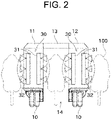
- FIG. 2 is a back view of the pest control vehicle 1.
- a direction in which the pest control vehicle 1 travels when spraying chemical liquid is determined as the front side, and the front, back, left, and right sides are defined. Accordingly, a vehicle width direction coincides with the left-right direction, and a vehicle length direction coincides with the front-back direction.
- a left and right pair (or front and back pair) of components disposed in the pest control vehicle 1 are designated with the same reference numbers, and descriptions thereof may be omitted or simplified.
- the pest control vehicle 1 is a vehicle that sprays chemical liquid on plants 100 (spray target objects, work target objects) raised on a farm or the like.
- the plants 100 are, for example, orchard trees but may be vegetables.
- the pest control vehicle 1 includes crawler traveling portions 10, a left vehicle body 11, a right vehicle body 12, and an upper vehicle body 13.
- the crawler traveling portions 10 are each a hydraulic type, and hydraulic oil is supplied to a hydraulic motor (not illustrated) to rotate a drive sprocket. Accordingly, crawlers wound on the drive sprockets, driving wheels, or the like rotate to allow the pest control vehicle 1 to travel. Further, by differentiating driving speeds of the left and right crawler traveling portions 10, the pest control vehicle 1 can turn. Furthermore, differentiating driving directions of the left and right crawler traveling portions 10, the pest control vehicle 1 can turn without changing the position.
- the left vehicle body 11 is mainly supported by the left crawler traveling portion 10.
- the left vehicle body 11 includes a frame and a cover covering the frame.
- the right vehicle body 12 is mainly supported by the right crawler traveling portion 10.
- the right vehicle body 12 includes a frame and a cover covering the frame.
- Upper portions of the left vehicle body 11 and the right vehicle body 12 are connected by the upper vehicle body 13.
- a passage space 14 surrounded by the left vehicle body 11, the right vehicle body 12, and the upper vehicle body 13 is formed.
- the passage space 14 is a space in which components are not disposed from the ground to a predetermined height and through which the plants 100 can pass when the pest control vehicle 1 travels.
- the left and right crawler traveling portions 10 travel while sandwiching the plants 100 in the left-right direction.
- the pest control vehicle 1 travels in the farm while straddling the plants 100.
- An engine 21 is disposed in the left vehicle body 11.
- the engine 21 generates drive force to allow the pest control vehicle 1 to travel (power to operate a hydraulic motor). Note that the engine 21 may be disposed in the right vehicle body 12.
- a chemical liquid tank 22 is disposed in the right vehicle body 12. Chemical liquid is stored in the chemical liquid tank 22.
- the chemical liquid stored in the chemical liquid tank 22 is medical agent having a function such as moth proofing, insect killing, or weeding. Note that the chemical liquid tank 22 may be disposed in the left vehicle body 11.
- injection units 30 are respectively disposed on back surfaces of the left vehicle body 11 and the right vehicle body 12. Each of the injection units 30 sprays the chemical liquid to both the left and right sides. Consequently, as illustrated in FIG. 2 , the pest control vehicle 1 can simultaneously spray the chemical liquid on a right portion of the plant 100 on the left side of the pest control vehicle 1, both left and right portions of the plant 100 passing through the passage space 14, and a left portion of the plant 100 on the right side of the pest control vehicle 1.
- the injection units 30 may be disposed front surfaces of the left vehicle body 11 and the right vehicle body 12. The configuration of the injection unit 30 will be described below in detail.
- the pest control vehicle 1 is configured to autonomously travel in the farm. In other words, the pest control vehicle 1 detects its current position by using GNSS or the like. Additionally, an autonomous travel route is created in advance based on position information of the farm. With such a configuration, the pest control vehicle 1 sprays the chemical liquid on the plants 100 while autonomously traveling based on the current position and the autonomous travel route.
- the pest control vehicle 1 is not limited to a vehicle that autonomously travels.
- the pest control vehicle 1 may be, for example, a vehicle that travels by remote control.
- the remote control is referred to as control in which an operation by an operator located away from the pest control vehicle 1 (that is, an operator not riding on the pest control vehicle 1) allows the pest control vehicle 1 to travel or allows the pest control vehicle 1 to spray the chemical liquid.
- FIG. 3 is a cross-sectional perspective view of a cylindrical member 31.
- the left and right injection units 30 are configured in the same manner or are configured symmetrically with respect to a plane passing through the center in the vehicle width direction. Therefore, the left and right injection units 30 will be summarized and described below. As illustrated in FIGS. 1 and 2 , the injection unit 30 includes two cylindrical members 31 disposed side by side on the left side and the right side. In other words, in the present embodiment, since two cylindrical members 31 are disposed on the left side and two cylindrical members 31 are disposed on the right side, a total of four cylindrical members 31 are disposed.
- the cylindrical member 31 is disposed to extend in the up-down direction.
- the cylindrical member 31 is an elongated member, and is disposed such that its longitudinal direction substantially coincides with the up-down direction (vehicle height direction). Note that, for example, even when the longitudinal direction of the cylindrical member 31 is deviated from the up-down direction by few angles, the longitudinal direction of the cylindrical member 31 is defined to substantially coincide with the up-down direction (that is, the cylindrical member 31 extends in the up-down direction).
- the cylindrical member 31 is formed in a cylinder, and a space is formed inside.
- the cylindrical member 31 is made of resin and is integrally molded with a mold. Note that the cylindrical member 31 may be made of a material other than resin. As illustrated in FIG. 3 , a chemical liquid passage 31a and an air passage 31b are formed inside the cylindrical member 31.
- the chemical liquid passage 31a is a space through which the chemical liquid passes.
- the chemical liquid passage 31a is a passage extending in the up-down direction.
- a chemical liquid hose 34 is connected to the chemical liquid passage 31a. Specifically, an upper end of the chemical liquid passage 31a is opened.
- the chemical liquid passage 31a is configured such that a coupler of the chemical liquid hose 34 is connectable to the upper end.
- the chemical liquid hose 34 is connected to the chemical liquid tank 22.
- a pump (not illustrated) is disposed in a pathway that connects the chemical liquid passage 31a to the chemical liquid tank 22. The chemical liquid in the chemical liquid tank 22 is pumped to the chemical liquid passage 31a.
- a pathway of the chemical liquid hose 34 may be disposed in any manner but is preferably disposed so as not to pass through the passage space 14.
- the chemical liquid hose 34 connected to the left chemical liquid passage 31a is preferably connected through the upper vehicle body 13 to the chemical liquid tank 22.
- a plurality of chemical liquid injection portions 32 are disposed on the cylindrical member 31.
- the chemical liquid injection portions 32 are each a nozzle from which the chemical liquid is injected.
- the chemical liquid injection portions 32 are disposed side by side in the up-down direction.
- the chemical liquid injection portions 32 are disposed in a direction enabling the aforementioned chemical liquid to be sprayed.
- the chemical liquid injection portions 32 are disposed on a left surface of the left cylindrical member 31, and the chemical liquid injection portions 32 are disposed on a right surface of the right cylindrical member 31. The same applies to the right vehicle body 12.
- the air passage 31b is a space through which air (particularly, compressed air) for supporting the chemical liquid to be sprayed passes.
- the air passage 31b is a passage extending in the up-down direction.
- the air passage 31b and the chemical liquid passage 31a are formed at positions aligned in the front-back direction.
- the air passage 31b is formed on the front side of the chemical liquid passage 31a (in other words, at a near side of the vehicle body with respect to the chemical liquid passage 31a).
- the air passage 31b may be formed on the back side of the chemical liquid passage 31a (in other words, at a far side of the vehicle body with respect to the chemical liquid passage 31a).
- a blower hose 35 is connected to the air passage 31b. Specifically, an upper end of the air passage 31b is opened.
- the air passage 31b is configured such that a coupler of the blower hose 35 is connectable to the upper end.
- the blower hose 35 is connected to a blower device 36.
- a portion of the blower hose 35 is a flexible hose that is extendable.
- the blower device 36 sucks air in or sends the air to generate compressed air and send the compressed air.
- the blower device 36 is disposed on the level higher than the cylindrical member 31.
- One blower device 36 is disposed on the left vehicle body 11 and one blower device 36 is disposed on the right vehicle body, and thus a total of two blower devices 36 are disposed.
- the blower device 36 is disposed such that a portion is exposed from the vehicle body to suck outside air in.
- the single blower device 36 supplies air to the two cylindrical members 31; however, the blower device 36 may be disposed for each of the cylindrical members 31.
- a plurality of air injection portions 33 are disposed in the cylindrical member 31.
- the air injection portions 33 are each a hole through which air is injected.
- the air injection portion 33 may be a nozzle.
- the air injection portions 33 are disposed side by side in the up-down direction.
- the air injection portions 33 are formed on the same side of the left and right surfaces of the cylindrical member 31 as the chemical liquid injection portions 32 are formed.
- Spraying of the chemical liquid is supported by the air injected from the air injection portions 33. Specifically, the chemical liquid is splashed by the air, and thus the chemical liquid can be uniformly applied.
- the air to be injected is increased, and thus a distance in which the chemical liquid is sprayed can be increased.
- the number of air injection portions 33 disposed in the single cylindrical member 31 is greater than the number of chemical liquid injection portions 32 disposed in the single cylindrical member 31.
- the chemical liquid can be uniformly sprayed while the number of chemical liquid injection portions 32 is suppressed.
- the number of chemical liquid injection portion 32 may be equal to the number of air injection portions 33 or the number of chemical liquid injection portion 32 may be greater than the number of air injection portions 33.
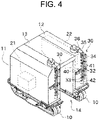
- FIG. 4 is a perspective view of the pest control vehicle 1 according to the second embodiment.
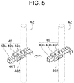
- FIG. 5 is a perspective view illustrating a configuration for changing a sprayed position of the chemical liquid by a support member 40. Note that in the following descriptions, a member that is the same as or similar to that in the aforementioned embodiment is designated with the same reference number, and the description thereof may be omitted.
- the chemical liquid and the air pass through the cylindrical member 31.
- the chemical liquid and the air pass through different members in the second embodiment.
- the injection unit 30 of the second embodiment includes chemical liquid ducts 41 and an air duct 42 instead of the cylindrical members 31.
- the chemical liquid ducts 41 each include a function similar to that of the chemical liquid passage 31a. Therefore, the chemical liquid hose 34 is connected to the chemical liquid duct 41, and the chemical liquid in the chemical liquid tank 22 is supplied to the chemical liquid duct 41. Further, the chemical liquid injection portions 32 are disposed on the chemical liquid duct 41, and the chemical liquid is injected.
- the air duct 42 includes a function similar to that of the air passage 31b. Therefore, the blower hose 35 is connected to the air duct 42, and the air sent from the blower device 36 is supplied to the air duct 42. Furthermore, the air injection portions 33 are disposed on the air duct 42, and the air is injected.
- the single air duct 42 supports the air to be sprayed by the two chemical liquid ducts 41.
- the single air duct 42 is disposed on each of the left vehicle body 11 and the right vehicle body 12.
- a left and right pair of chemical liquid ducts 41 are disposed on the air duct 42.
- the air injection portions 33 are formed on both left and right sides of the air duct 42.
- the air duct 42 is attached via the support member 40 to the left vehicle body 11 or the right vehicle body 12.
- the support member 40 includes a base portion 40a, a slide portion 40b, and fixation members 40c.
- the base portion 40a is fixed to the left vehicle body 11 or the right vehicle body 12.
- the slide portion 40b is configured to be slidable in the left-right direction to the base portion 40a.
- the air duct 42 is fixed to the slide portion 40b so as not to move relative thereto.
- the chemical liquid ducts 41 are fixed to the air duct 42.
- Attachment holes 401 are formed side by side in the left-right direction and at predetermined intervals L in the base portion 40a.
- Attachment holes 402 are formed in the slide portion 40b at the same intervals L or at intervals, each of which is integral multiple of L.
- first embodiment and the second embodiment can be combined.
- configuration of the second embodiment allowing the position in the left-right direction to be adjusted can be applied to the first embodiment.
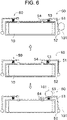
- the pest control vehicle 1 of the first embodiment and the second embodiment includes a contact detection mechanism 50 illustrated in FIG. 6.
- FIG. 6 is a schematic plan view illustrating a configuration of the contact detection mechanism 50 attached to the left crawler traveling portion 10.
- contact type sensors are installed on the front, back, left, and right sides.
- the contact type sensor needs to be replaced.
- this type of contact type sensor tends to be an expensive product, which leads to an increase of costs for replacement.
- the contact detection mechanism 50 that detects a contact of an obstacle or the like by using magnet switches 54 as non-contact type sensors is provided in the present embodiment.
- the contact detection mechanism 50 includes a contact bar 51, a rotary shaft portion 52, a spring 53, and the magnet switches 54.
- the contact bar 51 is formed in an L-shape.
- the contact bars 51 are disposed to cover two sides (for example, the front and left sides) of the crawler traveling portion 10 in a plan view.
- the contact bar 51 is configured to be rotatable about the rotary shaft portion 52 at one end of the contact bar 51. Further, in order to prevent the contact bar 51 from coming into contact with the crawler traveling portion 10 due to the rotation of the contact bar 51, the contact bar 51 is connected via the spring 53 to the crawler traveling portion 10. Furthermore, the magnet switches 54 are respectively disposed at the other end of the contact bar 51 and the crawler traveling portion 10.
- the contact bar 51 rotates in the same direction.
- the positions of the two magnet switches 54 come close, and thus a contact can be detected.
- the non-contact type sensors the frequency of replacement of which is low are used, and the single sensor can detect contacts in the two directions. Therefore, a contact with an obstacle 101 in four directions can be detected.
- the pest control vehicle 1 of the present embodiment includes the crawler traveling portions 10, the chemical liquid tank 22, and the cylindrical members 31.
- the chemical liquid tank 22 stores the chemical liquid for pest control.
- a space is formed inside the cylindrical member 31.
- the cylindrical member 31 includes the chemical liquid passage 31a, the chemical liquid injection portions 32, the air passage 31b, and the air injection portions 33.
- the chemical liquid flows through the chemical liquid passage 31a.
- the chemical liquid injection portions 32 are connected to the chemical liquid passage 31a, and inject the chemical liquid.
- the air flows through the air passage 31b.
- the air injection portions 33 are connected to the air passage 31b, and inject the air and thus support the chemical liquid to be sprayed.
- the injection of the air supports the chemical liquid to be sprayed, and thus the chemical liquid can be appropriately sprayed. Additionally, since the cylindrical member includes the chemical liquid passage and the air passage, a compact structure can be realized.
- the pest control vehicle 1 of the present embodiment includes the crawler traveling portions 10, the chemical liquid tank 22, the chemical liquid ducts 41, the chemical liquid injection portions 32, the air ducts 42, and the air injection portions 33.
- the chemical liquid tank 22 stores the chemical liquid for pest control.
- the chemical liquid flows through the chemical liquid duct 41.
- the chemical liquid injection portions 32 are connected to the chemical liquid duct 41, and inject the chemical liquid.
- the air flows through the air duct 42.
- the air injection portions 33 are connected to the air duct, and inject the air and thus support the chemical liquid to be sprayed.
- the injection of the air supports the chemical liquid to be sprayed, and thus the chemical liquid can be appropriately sprayed.
- the left and right pairs of air ducts 42 are disposed at the interval L.
- the chemical liquid duct 41 to which the chemical liquid injection portions 32 that spray the chemical liquid toward the left side are connected, and the chemical liquid duct 41 to which the chemical liquid injection portions 32 that spray the chemical liquid toward the right side are connected are disposed on the left air duct 42.
- the chemical liquid duct 41 to which the chemical liquid injection portions 32 that spray the chemical liquid toward the left side are connected, and the chemical liquid duct 41 to which the chemical liquid injection portions 32 that spray the chemical liquid toward the right side are connected are disposed on the right air duct 42.
- the chemical liquid can be sprayed in four directions by traveling one time. Additionally, compared to a configuration in which the chemical liquid injection portions for the left side and the chemical liquid injection portions for the right side are attached to the single chemical liquid duct, a compact configuration can be provided.
- the pest control vehicle 1 of the present embodiment includes the blower device 36 that supplies the air to the air passage 31b.
- the blower device 36 is disposed above the air injection portions 33.
- the blower device 36 is disposed at a position that does not disturb spraying of the chemical liquid from the cylindrical members 31.
- the left and right pair of cylindrical members 31 are disposed on the left vehicle body 11; however, the single cylindrical member 31 may be disposed on the left vehicle body 11. In this case, the single cylindrical member 31 is configured to inject the chemical liquid toward the left and right sides.
- the pest control vehicle 1 of the aforementioned embodiment travels with the crawlers but may travel with driving wheels.
Landscapes
- Life Sciences & Earth Sciences (AREA)
- Engineering & Computer Science (AREA)
- Insects & Arthropods (AREA)
- Pest Control & Pesticides (AREA)
- Wood Science & Technology (AREA)
- Zoology (AREA)
- Environmental Sciences (AREA)
- Catching Or Destruction (AREA)
- Special Spraying Apparatus (AREA)
- Spray Control Apparatus (AREA)
Applications Claiming Priority (1)
| Application Number | Priority Date | Filing Date | Title |
|---|---|---|---|
| JP2021064432A JP2022159942A (ja) | 2021-04-05 | 2021-04-05 | 防除車両 |
Publications (1)
| Publication Number | Publication Date |
|---|---|
| EP4070656A1 true EP4070656A1 (fr) | 2022-10-12 |
Family
ID=81328335
Family Applications (1)
| Application Number | Title | Priority Date | Filing Date |
|---|---|---|---|
| EP22166310.7A Pending EP4070656A1 (fr) | 2021-04-05 | 2022-04-01 | Véhicule de lutte contre les organismes nuisibles |
Country Status (2)
| Country | Link |
|---|---|
| EP (1) | EP4070656A1 (fr) |
| JP (1) | JP2022159942A (fr) |
Citations (7)
| Publication number | Priority date | Publication date | Assignee | Title |
|---|---|---|---|---|
| US5251818A (en) * | 1992-06-22 | 1993-10-12 | Technion Research & Development Foundation, Ltd. | Spraying equipment for plants grown in rows |
| FR2905559A1 (fr) * | 2006-09-07 | 2008-03-14 | Vermande Sa Sa | Dispositif et systeme pulverisateurs de produits phytosanitaires |
| FR2949293A1 (fr) * | 2009-09-01 | 2011-03-04 | Exel Ind | Equipement agricole de pulverisation, notamment dans un vignoble |
| EP1933988B1 (fr) * | 2005-10-11 | 2013-08-28 | Ivano Marcantoni | Transporteur a air vertical pour pulverisateurs agricoles |
| FR2989250A1 (fr) * | 2012-04-11 | 2013-10-18 | Bobard Jeune Sa Ets | Dispositif pour la pulverisation ou la projection d'un produit, notamment d'un produit phytosanitaire pour la vigne |
| EP3315026B1 (fr) * | 2016-10-28 | 2020-05-13 | Ivano Marcantoni | Appareil de distribution d'air pour pulvérisateurs agricoles |
| JP2020152285A (ja) | 2019-03-22 | 2020-09-24 | ヤンマーパワーテクノロジー株式会社 | 農作業用車両 |
-
2021
- 2021-04-05 JP JP2021064432A patent/JP2022159942A/ja active Pending
-
2022
- 2022-04-01 EP EP22166310.7A patent/EP4070656A1/fr active Pending
Patent Citations (8)
| Publication number | Priority date | Publication date | Assignee | Title |
|---|---|---|---|---|
| US5251818A (en) * | 1992-06-22 | 1993-10-12 | Technion Research & Development Foundation, Ltd. | Spraying equipment for plants grown in rows |
| EP1933988B1 (fr) * | 2005-10-11 | 2013-08-28 | Ivano Marcantoni | Transporteur a air vertical pour pulverisateurs agricoles |
| FR2905559A1 (fr) * | 2006-09-07 | 2008-03-14 | Vermande Sa Sa | Dispositif et systeme pulverisateurs de produits phytosanitaires |
| FR2949293A1 (fr) * | 2009-09-01 | 2011-03-04 | Exel Ind | Equipement agricole de pulverisation, notamment dans un vignoble |
| FR2989250A1 (fr) * | 2012-04-11 | 2013-10-18 | Bobard Jeune Sa Ets | Dispositif pour la pulverisation ou la projection d'un produit, notamment d'un produit phytosanitaire pour la vigne |
| EP3315026B1 (fr) * | 2016-10-28 | 2020-05-13 | Ivano Marcantoni | Appareil de distribution d'air pour pulvérisateurs agricoles |
| JP2020152285A (ja) | 2019-03-22 | 2020-09-24 | ヤンマーパワーテクノロジー株式会社 | 農作業用車両 |
| WO2020195952A1 (fr) * | 2019-03-22 | 2020-10-01 | ヤンマー株式会社 | Véhicule de travail agricole |
Also Published As
| Publication number | Publication date |
|---|---|
| JP2022159942A (ja) | 2022-10-18 |
Similar Documents
| Publication | Publication Date | Title |
|---|---|---|
| JP7134121B2 (ja) | 農作業用車両 | |
| EP3469900B1 (fr) | Tige de pulvérisation | |
| KR101661707B1 (ko) | 무선조종 방제 장치 | |
| WO2018136616A1 (fr) | Faucheuse destinée à être fixée à un véhicule agricole | |
| US11491504B2 (en) | Sprayer apparatus and systems | |
| US20140259897A1 (en) | Infinitely Variable Planting or Spraying Device | |
| KR20100111595A (ko) | 무인 방제용 차량 | |
| EP4070656A1 (fr) | Véhicule de lutte contre les organismes nuisibles | |
| KR200478646Y1 (ko) | 약액 분사 장치 | |
| KR102234038B1 (ko) | 자동농업설비 및 자동이동시스템 | |
| KR20180109553A (ko) | 방향 전환이 용이한 다기능 농업용 무인반송차량 | |
| EP4082336B1 (fr) | Véhicule de lutte contre les organismes nuisibles | |
| US20250244771A1 (en) | Method for controlling work vehicle, work vehicle control program, work vehicle control system, and work vehicle | |
| KR101570200B1 (ko) | 유압구동방식의 동력분무기 | |
| KR200488377Y1 (ko) | 과수용 약액 분사장치 | |
| KR100472698B1 (ko) | 골프장용 방제차 | |
| JP3898436B2 (ja) | 無人走行式農業用車両 | |
| KR20240012696A (ko) | 방제기 | |
| KR20180066921A (ko) | 분사각 가변이 가능한 노즐을 갖는 자주식 살포기 | |
| CN116034971B (zh) | 一种农作物复合种植的喷雾机及喷雾控制方法 | |
| EP4595747A1 (fr) | Procédé de commande de véhicule de travail, programme de commande de véhicule de travail, système de commande de véhicule de travail et véhicule de travail | |
| EP4595729A1 (fr) | Procédé de commande de véhicule de travail, programme de commande de véhicule de travail, système de commande de véhicule de travail et véhicule de travail | |
| KR20250094528A (ko) | 무인 방제기 | |
| KR200226700Y1 (ko) | 비닐하우스용 약액분사장치 | |
| JPS627426Y2 (fr) |
Legal Events
| Date | Code | Title | Description |
|---|---|---|---|
| PUAI | Public reference made under article 153(3) epc to a published international application that has entered the european phase |
Free format text: ORIGINAL CODE: 0009012 |
|
| STAA | Information on the status of an ep patent application or granted ep patent |
Free format text: STATUS: THE APPLICATION HAS BEEN PUBLISHED |
|
| AK | Designated contracting states |
Kind code of ref document: A1 Designated state(s): AL AT BE BG CH CY CZ DE DK EE ES FI FR GB GR HR HU IE IS IT LI LT LU LV MC MK MT NL NO PL PT RO RS SE SI SK SM TR |
|
| STAA | Information on the status of an ep patent application or granted ep patent |
Free format text: STATUS: REQUEST FOR EXAMINATION WAS MADE |
|
| 17P | Request for examination filed |
Effective date: 20230411 |
|
| RBV | Designated contracting states (corrected) |
Designated state(s): AL AT BE BG CH CY CZ DE DK EE ES FI FR GB GR HR HU IE IS IT LI LT LU LV MC MK MT NL NO PL PT RO RS SE SI SK SM TR |
|
| STAA | Information on the status of an ep patent application or granted ep patent |
Free format text: STATUS: EXAMINATION IS IN PROGRESS |
|
| 17Q | First examination report despatched |
Effective date: 20241202 |