EP4070828B1 - Ensemble soupape de pompe d'administration de fluide - Google Patents
Ensemble soupape de pompe d'administration de fluide Download PDFInfo
- Publication number
- EP4070828B1 EP4070828B1 EP22167142.3A EP22167142A EP4070828B1 EP 4070828 B1 EP4070828 B1 EP 4070828B1 EP 22167142 A EP22167142 A EP 22167142A EP 4070828 B1 EP4070828 B1 EP 4070828B1
- Authority
- EP
- European Patent Office
- Prior art keywords
- fluid
- fluid path
- movable portion
- pump
- detent
- Prior art date
- Legal status (The legal status is an assumption and is not a legal conclusion. Google has not performed a legal analysis and makes no representation as to the accuracy of the status listed.)
- Active
Links
Images







Classifications
-
- A—HUMAN NECESSITIES
- A61—MEDICAL OR VETERINARY SCIENCE; HYGIENE
- A61M—DEVICES FOR INTRODUCING MEDIA INTO, OR ONTO, THE BODY; DEVICES FOR TRANSDUCING BODY MEDIA OR FOR TAKING MEDIA FROM THE BODY; DEVICES FOR PRODUCING OR ENDING SLEEP OR STUPOR
- A61M5/00—Devices for bringing media into the body in a subcutaneous, intra-vascular or intramuscular way; Accessories therefor, e.g. filling or cleaning devices, arm-rests
- A61M5/14—Infusion devices, e.g. infusing by gravity; Blood infusion; Accessories therefor
- A61M5/168—Means for controlling media flow to the body or for metering media to the body, e.g. drip meters, counters ; Monitoring media flow to the body
- A61M5/16804—Flow controllers
- A61M5/16809—Flow controllers by repeated filling and emptying of an intermediate volume
-
- A—HUMAN NECESSITIES
- A61—MEDICAL OR VETERINARY SCIENCE; HYGIENE
- A61M—DEVICES FOR INTRODUCING MEDIA INTO, OR ONTO, THE BODY; DEVICES FOR TRANSDUCING BODY MEDIA OR FOR TAKING MEDIA FROM THE BODY; DEVICES FOR PRODUCING OR ENDING SLEEP OR STUPOR
- A61M5/00—Devices for bringing media into the body in a subcutaneous, intra-vascular or intramuscular way; Accessories therefor, e.g. filling or cleaning devices, arm-rests
- A61M5/14—Infusion devices, e.g. infusing by gravity; Blood infusion; Accessories therefor
- A61M5/168—Means for controlling media flow to the body or for metering media to the body, e.g. drip meters, counters ; Monitoring media flow to the body
- A61M5/16877—Adjusting flow; Devices for setting a flow rate
- A61M5/16881—Regulating valves
-
- A—HUMAN NECESSITIES
- A61—MEDICAL OR VETERINARY SCIENCE; HYGIENE
- A61M—DEVICES FOR INTRODUCING MEDIA INTO, OR ONTO, THE BODY; DEVICES FOR TRANSDUCING BODY MEDIA OR FOR TAKING MEDIA FROM THE BODY; DEVICES FOR PRODUCING OR ENDING SLEEP OR STUPOR
- A61M39/00—Tubes, tube connectors, tube couplings, valves, access sites or the like, specially adapted for medical use
- A61M39/22—Valves or arrangement of valves
-
- A—HUMAN NECESSITIES
- A61—MEDICAL OR VETERINARY SCIENCE; HYGIENE
- A61M—DEVICES FOR INTRODUCING MEDIA INTO, OR ONTO, THE BODY; DEVICES FOR TRANSDUCING BODY MEDIA OR FOR TAKING MEDIA FROM THE BODY; DEVICES FOR PRODUCING OR ENDING SLEEP OR STUPOR
- A61M5/00—Devices for bringing media into the body in a subcutaneous, intra-vascular or intramuscular way; Accessories therefor, e.g. filling or cleaning devices, arm-rests
- A61M5/14—Infusion devices, e.g. infusing by gravity; Blood infusion; Accessories therefor
- A61M5/142—Pressure infusion, e.g. using pumps
- A61M5/14244—Pressure infusion, e.g. using pumps adapted to be carried by the patient, e.g. portable on the body
-
- A—HUMAN NECESSITIES
- A61—MEDICAL OR VETERINARY SCIENCE; HYGIENE
- A61M—DEVICES FOR INTRODUCING MEDIA INTO, OR ONTO, THE BODY; DEVICES FOR TRANSDUCING BODY MEDIA OR FOR TAKING MEDIA FROM THE BODY; DEVICES FOR PRODUCING OR ENDING SLEEP OR STUPOR
- A61M5/00—Devices for bringing media into the body in a subcutaneous, intra-vascular or intramuscular way; Accessories therefor, e.g. filling or cleaning devices, arm-rests
- A61M5/14—Infusion devices, e.g. infusing by gravity; Blood infusion; Accessories therefor
- A61M5/168—Means for controlling media flow to the body or for metering media to the body, e.g. drip meters, counters ; Monitoring media flow to the body
- A61M5/16804—Flow controllers
- A61M5/16813—Flow controllers by controlling the degree of opening of the flow line
-
- A—HUMAN NECESSITIES
- A61—MEDICAL OR VETERINARY SCIENCE; HYGIENE
- A61M—DEVICES FOR INTRODUCING MEDIA INTO, OR ONTO, THE BODY; DEVICES FOR TRANSDUCING BODY MEDIA OR FOR TAKING MEDIA FROM THE BODY; DEVICES FOR PRODUCING OR ENDING SLEEP OR STUPOR
- A61M2205/00—General characteristics of the apparatus
- A61M2205/02—General characteristics of the apparatus characterised by a particular materials
- A61M2205/0266—Shape memory materials
Definitions
- the present disclosure generally relates to a pump for infusing a patient with a fluid, for example, a pump arranged within a wearable medicament delivery system, and, in particular, a multi-state valve for controlling the flow of the fluid through the pump.
- Non-limiting examples of medicaments may include chemotherapy drugs, hormones (for instance, insulin), pain relief medications, and other types of liquid-based drugs.
- wearable medicament delivery devices are relatively small form factors that may be adhered to the skin of the patient, with a reservoir to hold the medicament.
- the device may include a needle or cannula fluidically coupled to the reservoir and extending from the device and into the skin of the patient.
- a pump may operate to force the fluid from the reservoir, through a fluid path, and out through the needle and into the patient (as e.g. disclosed in US 2020/0338262 A1 ).
- a control system with hardware and/or software elements, may be arranged within the device to manage medicament delivery and other device features.
- the control system may operate alone or in combination with an external computing device, such as a patient smartphone, healthcare provider computer, and/or the like.
- Minimizing the footprint of a wearable medicament delivery device makes the device less obtrusive to the patient and improves the overall user experience. Accordingly, developers are consistently under pressure to reduce the size of operating components, while increasing the features (for example, monitoring patient physiological information, increasing automation, and/or the like) while limiting power demands.
- components are required to be smaller and more compact.
- current pumping mechanisms include a valve switch to allow a user to fill the reservoir and to dispense a medicament. The valve must be shut while the user fills the reservoir, and open when the pump begins working. The valve must also differentiate between filling and dispensing of the pump.
- valve for example, closed, open for filling, and open for dispensing. Accordingly, conventional pump systems are not able to efficiently and effectively manage fluid flow within a device while meeting the space and energy demands of devices that are desired by patients.
- the present invention is directed to a fluid pump system for a wearable fluid delivery device as defined in claim 1.
- the wearable fluid delivery device may be configured to deliver a medicament to a patient, the medicament comprising insulin.
- the movable portion may include a bistable mechanism.
- the state of the fluid path may include one of a fluid delivery state to deliver the fluid to the patient from the pump chamber or a fluid fill state to fill the pump chamber from a reservoir in fluid communication with the fluid path.
- the actuator may include a shape memory alloy.
- the offset may include a substantially triangular projection extending from the movable portion.
- the fluid pump may include a spring configured to bias the shaft in a direction toward the movable portion in the absence of the force of the actuator.
- the shaft may include a detent arm.
- the movable portion may be associated with a first magnet attracted to a portion of the fixed portion to maintain the movable portion in contact with the fixed portion on a closed side of the fluid path valve until the shaft engages the movable portion to pivot the movable portion.
- the V-feature may include at least one channel for shaft to travel during operation of the fluid path valve.
- the at least one channel may include a sloped channel with at least one drop-off element to prevent the shaft from engaging an inner wall of the movable portion when traveling toward a central V-section of the V-feature.
- the described technology generally relates to a wearable fluid delivery device for delivering a fluid to a patient.
- the fluid may be or may include a medicament.
- the wearable fluid delivery device may include a reservoir for holding the fluid, a fluid path in fluid communication with the reservoir, a needle in fluid communication with the fluid path to deliver the fluid to the patient wearing the wearable fluid delivery device, and a fluid delivery pump configured to force the fluid from the reservoir, through the fluid delivery path, and into the patient via the needle.
- a fluid path valve or switch may be within, or in fluid communication with, the fluid path.
- the fluid path valve may be configured to alternate between multiple states or positions to configure the flow of the fluid through the fluid path.
- operation of the fluid delivery pump may be configured to alternate between filling a pump chamber with fluid from the reservoir and pumping the fluid from the pump chamber into the patient.
- the fluid path valve may be set into a first state for filling the pump chamber and a second state to allow operation of the pump to move the fluid from the pump chamber and into the patient.
- the fluid path valve may be a bistable valve having two stable positions.
- the fluid path valve may be or may include a "push-push" mechanism configured to actuate between at least two states.
- the fluid path valve may be or may include a bistable push-push mechanism.
- bistable push-push mechanism may enter two possible states, alternating between each state with each "push" or actuation.
- a bistable push-push mechanism may enter a first state responsive to a first actuation
- a second actuation may cause the bistable push-push mechanism to enter a second state
- a third actuation may cause the bistable push-push mechanism to re-enter the first state
- a fourth actuation may cause the bistable push-push mechanism to re-enter the second state, and so on.
- a pump such as a reciprocating pump, may require a fluid path that alternates between filling a pump chamber with fluid from a reservoir, and pumping fluid from the chamber into the patient.
- One example technique to accomplish this is by incorporating an independent actuator to alternate the system between these two states, which would decrease the required load on the pumping actuators.
- a shape-memory alloy (SMA) wire or other actuator may be used to drive the system; however, one actuator is only able to control one direction of movement in the system, which would be ineffective or greatly increase energy consumption if the actuator needed to hold the fluid path in one position.
- SMA shape-memory alloy
- a mechanism to reliably alternate between two or more positions is required.
- a detent or detent arm, arm, rod, shaft, pin, rod, push-push element, and/or the like
- an actuator for example, via an SMA wire and/or a spring
- a fluid pathway for instance, as a fluid pathway valve
- the system may reliably rest in two positions (for instance, a fluid fill state and a fluid delivery state).
- the general shape of the path may be or may substantially be a "V" shape, for example, where the inside will be attached to a bistable mechanism that is fixed at the center (see, for example, FIGS. 4B and 5 ).
- an inner corner of the wall of the path may be offset from the outer corner, which may change based on the configuration of the bistable mechanism. By offsetting the corner of the inner wall, the detent may reliably move to one side of the V-shaped path. The configuration of the bistability may be altered when the detent contacts it and causes it to deflect at each of the top points of the V-shaped path (see, for example, FIG. 5 ).
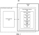
- FIG. 1 illustrates an example of an operating environment 100 that may be representative of some embodiments.
- operating environment 100 may include a fluid delivery system 105.
- fluid delivery system 105 may include a control or computing device 110 that, in some embodiments, may be communicatively coupled to a fluid delivery device 160.
- Computing device 110 may be or may include one or more logic devices, including, without limitation, a server computer, a client computing device, a personal computer (PC), a workstation, a laptop, a notebook computer, a smart phone, a tablet computing device, a personal diabetes management (PDM) device, and/or the like. Embodiments are not limited in this context.
- Fluid delivery device 160 may be or may include a wearable automatic fluid delivery device directly coupled to patient 150, for example, directly attached to the skin of the user via an adhesive and/or other attachment component.
- fluid delivery device 160 may be or may include a medicament delivery device configured to deliver a liquid medicament, drug, therapeutic agent, or other medical fluid to a patient.
- medicaments may include insulin, GLP-1, pramlintide, glucagon, pain relief drugs, hormones, blood pressure medicines, morphine, methadone, chemotherapy drugs, proteins, antibodies, a co-formulation of more than one of the foregoing, and/or the like.
- fluid delivery device 160 may be or may include an automatic insulin delivery (AID) device configured to deliver insulin (and/or other medication) to patient 150.
- AID automatic insulin delivery
- fluid delivery device 160 may be or may include a device the same or similar to an OmniPod ® device or system provided by Insulet Corporation of Acton, Massachusetts, United States, for example, as described in United States Patent Nos. 7,303,549 ; 7, 137,964 ; and/or 6,740,059.
- an AID device and insulin are used in examples in the present disclosure, embodiments are not so limited, as fluid delivery device 160 may be or may include a device capable of storing and delivering any fluid therapeutic agent, drug, medicine, hormone, protein, antibody, and/or the like.
- Fluid delivery device 160 may include a delivery system 162 having a number of components to facilitate automated delivery of a fluid to patient 150, including, without limitation, a reservoir 164 for storing the fluid, a pump 166 for transferring the fluid from reservoir 164, through a fluid path or conduit, and into the body of patient 150, and/or a power supply 168.
- Fluid delivery device 160 may include at least one penetration element (not shown) configured to be inserted into the skin of the patient to operate as a conduit between reservoir 164 and patient 150.
- penetration element may include a cannula and/or a needle.
- delivery system 162 may include more or fewer components.
- fluid delivery device 160 may include at least one sensor 170 operative to detect, measure, or otherwise determine various physiological characteristics of patient 150.
- sensor 170 may be or may include a continuous glucose monitoring (CGM) sensor operative to determine blood glucose measurement values of patient 150.
- CGM continuous glucose monitoring
- sensor may be or may include a heart rate sensor, temperature sensor, and/or the like.
- fluid delivery device 160 may be a closed-loop fluid delivery system using sensor 170 as an internal monitor to track patient information, either directly or via control device 110, to delivery system 162 to formulate delivery of a fluid to patient 150 via the penetration element.
- computing device 110 may be a smart phone, PDM, or other mobile computing form factor in wired or wireless communication with fluid delivery device 160.
- computing device 110 and Fluid delivery device 160 may communicate via various wireless protocols, including, without limitation, Wi-Fi (i.e., IEEE 802.11), radio frequency (RF), Bluetooth TM , Zigbee TM , near field communication (NFC), Medical Implantable Communications Service (MICS), and/or the like.
- computing device 110 and fluid delivery device 160 may communicate via various wired protocols, including, without limitation, universal serial bus (USB), Lightning, serial, and/or the like.
- USB universal serial bus
- computing device 110 (and components thereof) and fluid delivery device 160 are depicted as separate devices, embodiments are not so limited.
- computing device 110 and fluid delivery device 160 may be a single device. In another example, some or all of the components of computing device 110 may be included in fluid delivery device 160.
- Fluid delivery device 160 may include processor circuitry, memory unit, and/or the like.
- each of computing device 110 and fluid delivery device 160 may include a separate processor circuitry, memory unit, and/or the like capable of facilitating insulin infusion processes according to some embodiments, either individually or in operative combination. Embodiments are not limited in this context.
- FIG. 2 illustrates an exemplary wearable fluid delivery device in accordance with the present disclosure.
- FIG. 2 depicts a top-down view of a wearable fluid delivery device 205.
- a wearable fluid delivery device 205 may include multiple systems to store and delivery a fluid to a patient.
- Fluid delivery device 205 may include one or more housings configured to enclose the multiple systems.
- wearable fluid delivery device 205 may include a pump 210.
- pump 210 may be or may include a reciprocating pump (see, for example, FIGS. 3 , 4A, and 4B ).
- wearable fluid delivery device 205 may include a reservoir 212 for storing a fluid. Reservoir may be in fluid communication with pump 210 for delivering the fluid to patient via needle 214.
- pump 210 may be a multi-dose reciprocating pump. In some embodiments, pump 210 may be configured to deliver about 0.25 microliters per pulse. In exemplary embodiments, pump 210 may have a footprint of about 23 millimeters (mm) ⁇ 28 mm ⁇ 12 mm.
- FIG. 3 illustrates an embodiment of a fluid delivery pump in accordance with the present disclosure.
- a fluid delivery pump 310 may include a ratchet or ratchet wheels 308 operably coupled to a snail cam (not shown, see, for example, FIG. 4A ), a reservoir inlet 304 fluidically coupled to a reservoir (not shown), and a patient outlet 306 fluidically coupled to a needle 302. Rotation of ratchet wheels 308 may cause fluid to flow from the reservoir to a pump chamber 344 or through needle 302 to patient depending on a flow path state, for instance, whether the pump is in a chamber fill state (fluid fill state) or a patient infusion state (fluid delivery state), respectively.
- a snail cam not shown, see, for example, FIG. 4A
- a reservoir inlet 304 fluidically coupled to a reservoir
- a patient outlet 306 fluidically coupled to a needle 302.
- Rotation of ratchet wheels 308 may cause fluid to flow from the reservoir to a pump
- a fluid path valve 330 may be configured to switch the flow path state of pump 310 from a first state (for instance, a fluid fill state or chamber fill state) to a second state (for instance, a fluid delivery state or patient infusion state).
- a first state for instance, a fluid fill state or chamber fill state
- a second state for instance, a fluid delivery state or patient infusion state
- fluid path valve 330 may include a fixed portion 332 and a movable portion 334.
- fixed portion 332 may be an outer wall of fluid path valve 330.
- fixed portion 332 may be a V-feature.
- movable portion 334 may pivot about a pivot point.
- movable portion 334 may be a pivotable inner wall of fluid path valve 330.
- movable portion 334 may be or may include a bistable push-push mechanism (push-push mechanism, bistable mechanism, or inner wall).
- a detent (or shaft, rod, pin, and/or the like) 320 may be configured to engage V-feature 332 and/or bistable mechanism 334 to set the state of fluid path valve 330.
- detent 320 may be coupled to a bracket 312 or other structure.
- forces intended to move detent 320 may be wholly or partially imparted on bracket 312 to move detent 320.
- forces intended to move detent 320 may be wholly or partially imparted directly on detent 320.
- element 334 is described in examples in the present disclosure as a bistable mechanism, push-push mechanism, or bistable push-push mechanism, embodiments are not so limited.
- element 334 may be or may include other mechanisms besides a bistable mechanism, push-push mechanism, or bistable push-push mechanism.
- element 334 is not limited to a bistable mechanism, push-push mechanism, or bistable push-push mechanism or may be a push-push mechanism with more than two states. Rather, use of examples of a bistable mechanism, push-push mechanism, or bistable push-push mechanism are intended to provide illustrative functional embodiments of element 334. Accordingly, element 334 may be or may include any mechanism, element, structure, and/or the like capable of operating according to some embodiments.
- element 332 is described in examples in the present disclosure as a V-feature, embodiments are not so limited.
- element 332 is not required to be "V" shaped. Rather, use of a "V" shape or the term V-feature are not intended to be limiting but are intended to provide illustrative functional embodiments of element 332.
- element 334 may be or may include any mechanism, element, structure, and/or the like, with various different shapes, capable of operating according to some embodiments.
- forces intended to move detent 320 may be wholly or partially imparted on bracket 312 to move detent 320 may be actuated or moved by an actuator 316.
- actuator may be or may include an SMA wire operably coupled to detent 320 and/or a bracket 312.
- a spring 318 may be operably coupled to detent 320 and/or a bracket 312.
- actuator 316 may impart a force on detent 320 to move detent in direction A (for instance, away from bistable mechanism 334).
- actuator 316 may impart a force on detent 320 to move detent in direction B (for instance, toward bistable mechanism 334).
- a spring 318 may operate to bias detent 320, for example, in the direction of arrow B. Accordingly, if actuator 316 is not providing a force to move detent 320 in the direction of arrow A, detent 320 may be biased in the direction of arrow B. For example, an SMA wire actuator 316 may be activated to move detent 320 in the direction of arrow A. Relaxation of SMA wire actuator 316 may cause detent 320 to move back in the direction of arrow B. In this manner, fluid path valve 330 may be switched between fluid path states (see, for example, FIGS. 6A-6E ).
- actuator 316, and other components of pump 310 may be actuated via hardware and/or software of a wearable fluid delivery device and/or an external computing device communicatively coupled to wearable fluid delivery device (see, for example, FIG. 1 ).
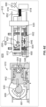
- FIGS. 4A and 4B illustrate an embodiment of a fluid delivery pump in accordance with the present disclosure. More specifically, FIGS. 4A and 4B show a cross-sectional side view and a front view, respectively, of a fluid delivery pump 410. In some embodiments, fluid delivery pump 410 may be a reciprocating pump.
- pump 410 may include a ratchet wheel 408, a snail cam 440, a piston 442, and a chamber 444.
- a fluid path of pump 410 may include a reservoir entrance to needle 450, a chamber/needle passthrough 446, and a needle 402 with a needle exit 452.
- a fluid path valve 430 may include a V-feature 432 and a bistable mechanism 434.
- fluid path valve 430 may be placed in a chamber fill state, for example in which a reservoir (not shown) is open to chamber 444 and closed to needle 402 (and patient). Rotation of ratchet 408 may rotate past the drop off of snail cam 440 and piston 442 may reset to chamber 444. Fluid path valve 430 may be switched to the patient infusion state, for example, in which chamber inlet 450 is closed to reservoir and needle 402 is open to chamber 444. In the patient infusion state, rotation of ratchet 408 may cause fluid to be pumped from chamber 444, through needle 402, and into the patient.
- FIG. 5 illustrates an embodiment of a fluid path valve in accordance with the present disclosure. More specifically, FIG. 5 depicts steps 570-575 of fluid path valve 530 as fluid path valve 530 transitions between states.
- fluid path valve 530 may include a fixed portion (or V-feature) 532 and a movable portion (or bistable mechanism) 534 operably coupled to a pivot element 560 configured to allow bistable mechanism 534 to pivot responsive to force provided by a shaft or detent 520.
- V-feature 532 and bistable mechanism 534 may form a path, for example, with V-feature 532 being configured as a fixed outer wall of the path and bistable mechanism 534 being an inner wall of the path (that pivots on pivot element 560).
- V-feature 532 may include a path, groove, inset, slot, wall, or other structure that may guide detent 520, for example, responsive to forces imparted by an actuator and/or spring.
- V-feature 532 may be offset or non-parallel and/or may include projections to cause detent 520 to deflect in a desired direction.
- bistable mechanism 534 may have an offset or projection 562 (for instance a tip of a triangular or substantially triangular portion) that may be offset to cause detent 520 to deflect in a desired direction.
- Projection 562 may form a first side, inner wall, extension, overhang, arm, or other structure 536 of bistable mechanism on a first side of projection 562 and a second side, inner wall, extension, overhang, arm, or other structure 538 on a second side of projection (first wall 536 and second wall 538 are only labeled in step 570 to limit the complexity of FIG. 5 ).
- Projection 562 may be offset to cause detent 520 to deflect in a desired direction to engage first wall 536 or second wall 538 to cause bistable mechanism to tilt, pivot, or otherwise move in a desired direction to change a state of fluid path valve 530.
- fluid path valve 530 may be in a first state (for example, a chamber fill state).
- Detent may be pulled in direction C' at step 570, for example, in response to an actuation by an SMA wire or other actuator (or conversely, due to the force of a biasing spring in the absence of actuation by an SMA wire).
- offset 562 for instance, a triangular projection
- bistable mechanism 534 may be configured to cause detent 520 to deflect in direction C (for instance, to the right) and contact second wall 538. For example, as detent 520 is pulled up toward bistable mechanism, detent 520 may hit at or near the point of the triangular projection of offset 562, causing detent 520 to veer into direction C.
- detent 520 may contact bistable mechanism 534 on the right side (for instance, at second wall 538), causing bistable mechanism 534 to rotate counterclockwise. Fluid delivery valve may now be in a second state, such as a patient infusion state, after rotating to create an opening between V-feature 534 and second wall 538.
- detent 520 may get pulled in direction D and come to a rest in a corner of V-feature 534.
- detent may be pulled in direction E', however, at this stage, the orientation of offset 562 of bistable mechanism 534 may cause detent 520 to deflect in direction E (for instance, to the left).
- detent 520 may contact bistable mechanism 534 on the left side (for instance, at first wall 536), cause bistable mechanism 534 to rotate clockwise.
- detent 520 may get pulled in direction F and come to a rest in a corner of V-feature 534.
- steps 570-575 may be repeated to switch the flow path from a first state (for instance, a chamber fill state) to a second state (for instance, a patient infusion state).
- a first state for instance, a chamber fill state
- a second state for instance, a patient infusion state
- steps 571-573, in which V-feature 534 is open on the upper right side may be a first state
- steps 570, 574, and 575, in which V-feature 534 is open on the upper left side may be a second state, or vice versa.
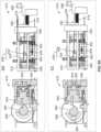
- FIGS. 6A-6E illustrate operation states of an embodiment of a fluid delivery pump in accordance with the present disclosure. More specifically, FIGS. 6A-6E depict steps 670-678 of a fluid infusion process (for instance, including chamber fill and patient infusion processes), depicting a cross-sectional side view and a front view for a pump 610 according to some embodiments.
- a fluid infusion process for instance, including chamber fill and patient infusion processes
- a pump 610 may include a ratchet 608, snail cam 640, piston 642 and chamber 644.
- a fluid path of pump 610 may include a reservoir entrance to needle 650, a chamber/needle passthrough 646, and a needle 602 with a needle exit 652.
- a fluid path valve 630 may include a V-feature 632 and a bistable mechanism 634.
- a detent 620 may be operably coupled to a bracket 312/612.
- An actuator 616 may be operably coupled to bracket 312 to impart a force on detent 620.
- actuator 616 may be or may include an SMA wire that, when activated, may pull detent 620.
- a spring 318/618 may be operably coupled to detent 320/620 and/or a bracket 312/612 to bias detent 320/620 (for instance, in the absence of a force by actuator 616).
- the fluid path is in a first position (for instance, a patient infusion position) such that rotation of ratchet wheel 608 may pump the fluid out of chamber 644 and into the patient.
- This infusion pulse may be repeated for multiple pulses, such as about 50 to about 100 pulses.
- Actuator 616 is deactivated, as indicated by X 690.
- ratchet wheel 608 may stop (indicated by X 691 as the drop off of snail cam 640 approaches.
- pump 610 may stop moving the fluid (as indicated by X 692) and the fluid path remains in the patient infusion position.
- SMA 616 is activated, pulling detent 620 in direction G.
- Detent 620 may center on V-feature 632 and the fluid path may move out of the patient infusion position.
- SMA 616 is deactivated, initiating SMA release, causing detent 620 to move in direction H.
- Detent 620 may contact and cause rotation (for instance, clockwise rotation) of bistable mechanism 634.
- the fluid path may move into a second position (for instance, a chamber fill position).
- SMA release continues such that detent 620 continues moving in direction H.
- Detent 620 further rotates bistable mechanism 634 and moves the fluid path into the chamber fill position.
- ratchet wheel 608 may rotate and piston 642 may fall off of the drop off of snail cam 640, creating a vacuum or negative pressure in chamber 644 that draws fluid from the reservoir, through 650 and into chamber 644.
- ratchet wheel 608 may stop moving and chamber 644 may be at least partially full of the fluid.
- the fluid path may be in a chamber fill (or non-infusion) position.
- SMA 616 may be activated, pulling detent 620 in direction H. Detent 620 may center on V-feature 632 and the fluid path may move out of the chamber fill position.
- SMA 616 may be deactivated and detent 620 may contact and rotate (for instance, counterclockwise) bistable mechanism 634. The fluid path may be moved into the patient infusion position.
- FIG. 7 illustrates an embodiment of a fluid path valve in accordance with the present disclosure.
- a fluid path valve 730 may include a V-feature 732 and a bistable mechanism 734.
- bistable mechanism 734 may include a beam 780.
- a shape of bistable mechanism 734 may be configured to reduce or even eliminate detent 720 from being caught, stuck, or otherwise trapped, either temporarily or permanently, in area 770 between bistable mechanism 734 and beam 780. This embodiment may be used in the system shown in earlier figures.
- FIG. 8 illustrates an embodiment of a fluid path valve in accordance with the present disclosure.
- a fluid path valve 830 may include a V-feature 832 and a bistable mechanism 834.
- bistable mechanism 834 may be associated with magnets.
- a bottom face of path 882 and an inside wall 880 may have opposite magnetic charges. Accordingly, when detent 820 reaches the top of the path and pushes inside wall 880 over center, the opposite poles may operate to facilitate complete motion and prevent bistable mechanism 834 from passing back over center as detent 820 returns to the bottom (or corner) of V-feature 832.
- the magnets may operate to maintain bistable mechanism 834 in contact with V-feature on a closed side of fluid path valve 830 until detent 820 engages bistable mechanism 834 to pivot bistable mechanism 834 (i.e., to prevent bistable mechanism 834 from swinging back after detent 820 moves toward the V-section (inner corner) of V-feature 832).
- This embodiment may be used in the system shown in earlier figures. Additionally or alternatively, there may be sufficient friction in the fluid path valve 830 such that when the bistable mechanism 834 rotates to one side, the friction in the fluid path valve 830 prevents the bistable mechanism 834 from rotating back to the center or toward the other side, until it is contacted again by detent 820.
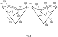
- FIG. 9 illustrates an embodiment of a fluid path valve in accordance with the present disclosure.
- a fluid path valve 930 may include a V-feature 932 and a bistable mechanism 934.
- a beam 960 may be fixed at the center where it is connected to the inner walls of the path, constrained on either side 980 of fluid path valve 930.
- detent 920 When detent 920 reaches a top of the path, detent 920 may cause the bends of beam 860 to invert, pushing the inner wall of bistable mechanism 934 over center.
- the bending forces and stresses of beam 960 may facilitate complete motion and prevent bistable mechanism 934 from passing back over center as detent 920 returns to the bottom (or corner) of V-feature 932.
- This embodiment may be used in the system shown in earlier figures.
- FIG. 10 illustrates an embodiment of a fluid path valve in accordance with the present disclosure.
- a fluid path valve 1030 may include a V-feature 1032 and a bistable mechanism 1034.
- V-feature 1032 may be associated with drop offs 1082 that may form paths or channels 1080.
- drop offs 1082 may cause detent 1020 to only move in the direction indicated by the arrows (and in the opposite direction during a return process) in FIG.
- the paths 1080 may slope up (for instance, out of the page of FIG. 10 ) in the direction of the arrows of FIG. 10 . This embodiment may be used in the system shown in earlier figures.
Landscapes
- Health & Medical Sciences (AREA)
- Heart & Thoracic Surgery (AREA)
- Hematology (AREA)
- Life Sciences & Earth Sciences (AREA)
- Engineering & Computer Science (AREA)
- Anesthesiology (AREA)
- Biomedical Technology (AREA)
- Veterinary Medicine (AREA)
- Public Health (AREA)
- General Health & Medical Sciences (AREA)
- Animal Behavior & Ethology (AREA)
- Vascular Medicine (AREA)
- Physics & Mathematics (AREA)
- Fluid Mechanics (AREA)
- Pulmonology (AREA)
- Infusion, Injection, And Reservoir Apparatuses (AREA)
Claims (9)
- Système de pompe à fluide (105) pour un dispositif portable d'administration de fluide (160), comprenant :une chambre de pompe (344 ; 444 ; 644) destinée à stocker un fluide ;un chemin de fluide en communication fluidique avec la chambre de pompe et un réservoir (164 ; 212) ;une soupape de chemin de fluide (330 ; 430 ; 530 ; 630 ; 730 ; 830 ; 930 ; 1030) fonctionnelle pour commander un état du chemin de fluide, la soupape de chemin de fluide comprenant une partie fixe (332 ; 432 ; 532 ; 632 ; 732 ; 832 ; 932 ; 1032) et une partie mobile (334 ; 434 ; 534 ; 634 ; 734 ; 834 ; 934 ; 1034) ;caractérisé par une tige comprenant un bras à encliquetage (320 ; 520 ; 620 ; 720 ; 820 ; 920 ; 1020) configuré pour se mouvoir le long de la partie fixe en réponse à une force transmise par un actionneur (316 ; 616),dans lequel la partie fixe comprend un organe en V présentant une forme sensiblement de V, et dans lequel la partie mobile comprend une saillie sensiblement triangulaire s'étendant depuis la partie mobile pour dévier une force de la tige pour amener la partie mobile à pivoter dans une étape d'une première position à une seconde position, et dans une autre étape de la seconde position à la première position, en réponse au fait que la tige entre en prise avec celle-ci pour changer l'état du chemin de fluide.
- Système de pompe de la revendication 1, le dispositif portable d'administration de fluide étant configuré pour administrer un médicament à un patient, le médicament comprenant de l'insuline.
- Système de pompe de l'une des revendications précédentes, la partie mobile comprenant un mécanisme bistable.
- Système de pompe de l'une des revendications précédentes, l'état du chemin de fluide comprenant un d'un état d'administration de fluide pour administrer le fluide au patient depuis la chambre de pompe ou un état de remplissage de fluide pour remplir la chambre de pompe depuis un réservoir en communication fluidique avec le chemin de fluide.
- Système de pompe de l'une des revendications précédentes, l'actionneur comprenant un alliage à mémoire de forme.
- Système de pompe de l'une des revendications précédentes, comprenant en outre un ressort (318) configuré pour solliciter la tige dans une direction vers la partie mobile en l'absence de la force de l'actionneur.
- Système de pompe de l'une des revendications précédentes, la partie mobile étant associée à un premier aimant attiré par une partie de la partie fixe pour maintenir la partie mobile en contact avec la partie fixe sur un côté fermé de la soupape de chemin de fluide jusqu'à ce que la tige entre en prise avec la partie mobile pour faire pivoter la partie mobile.
- Système de pompe de l'une des revendications précédentes, l'organe en V comprenant au moins une gorge pour le déplacement de la tige durant le fonctionnement de la soupape de chemin de fluide.
- Système de pompe de la revendication 8, l'au moins une gorge comprenant une gorge en pente avec au moins un élément d'abaissement pour empêcher la tige d'entrer en prise avec une paroi intérieure de la partie mobile lors du déplacement vers une section en V centrale de l'organe en V.
Applications Claiming Priority (1)
| Application Number | Priority Date | Filing Date | Title |
|---|---|---|---|
| US202163171813P | 2021-04-07 | 2021-04-07 |
Publications (2)
| Publication Number | Publication Date |
|---|---|
| EP4070828A1 EP4070828A1 (fr) | 2022-10-12 |
| EP4070828B1 true EP4070828B1 (fr) | 2024-10-16 |
Family
ID=81327992
Family Applications (1)
| Application Number | Title | Priority Date | Filing Date |
|---|---|---|---|
| EP22167142.3A Active EP4070828B1 (fr) | 2021-04-07 | 2022-04-07 | Ensemble soupape de pompe d'administration de fluide |
Country Status (2)
| Country | Link |
|---|---|
| US (1) | US20220323674A1 (fr) |
| EP (1) | EP4070828B1 (fr) |
Family Cites Families (6)
| Publication number | Priority date | Publication date | Assignee | Title |
|---|---|---|---|---|
| US4537387A (en) * | 1982-09-30 | 1985-08-27 | Anatros Corporation | Precision valve assembly |
| JPH10504254A (ja) * | 1994-08-17 | 1998-04-28 | ダエウー エレクトロニクス カンパニー リミテッド | 形状記憶合金を用いた弁及びこの弁を採用したアンチロックブレーキシステム |
| JP2004521667A (ja) | 2000-09-08 | 2004-07-22 | インシュレット コーポレイション | 患者の輸液のための装置、システム及び方法 |
| US6960192B1 (en) | 2002-04-23 | 2005-11-01 | Insulet Corporation | Transcutaneous fluid delivery system |
| CN103736165B (zh) * | 2006-02-09 | 2017-05-10 | 德卡产品有限公司 | 流体分配器件、流体流的测量方法和系统及流体输送系统 |
| EP3047873A1 (fr) * | 2015-01-22 | 2016-07-27 | ECP Entwicklungsgesellschaft mbH | Soupape magnétique pour la commande d'un flux de fluide à travers un cathéter |
-
2022
- 2022-04-07 EP EP22167142.3A patent/EP4070828B1/fr active Active
- 2022-04-07 US US17/715,536 patent/US20220323674A1/en active Pending
Also Published As
| Publication number | Publication date |
|---|---|
| EP4070828A1 (fr) | 2022-10-12 |
| US20220323674A1 (en) | 2022-10-13 |
Similar Documents
| Publication | Publication Date | Title |
|---|---|---|
| US10213549B2 (en) | Drug delivery device and methods therefor | |
| EP1513580B1 (fr) | Ensemble piston pour dispositif de perfusion pour malades | |
| EP1513573B1 (fr) | Assemblage de piston pour dispositif de perfusion de patient | |
| EP3675797B1 (fr) | Réservoir à capteur de faible volume | |
| EP3897778B1 (fr) | Dispositif et système pour administrer un fluide médical et méthode d'administration | |
| US9770556B2 (en) | Methods and apparatus for translating a continuous-deliver delivery profile into a plurality of periodic bolus deliveries | |
| US20230047034A1 (en) | Infusion pumps and methods with shape memory wire driven syringe mechanism | |
| EP4088761A1 (fr) | Surveillance d'état de réservoir | |
| EP3824184B1 (fr) | Pompe alternative | |
| EP4070828B1 (fr) | Ensemble soupape de pompe d'administration de fluide | |
| US20230201452A1 (en) | Infusion pumps and methods with shape memory wire driven syringe mechanism | |
| US20220362465A1 (en) | Methods and devices for determining fluid delivery pump information | |
| JP7838084B2 (ja) | 容積型ポンプの駆動機構 | |
| EP4079348B1 (fr) | Dispositif de distribution pour dispositif d'administration de médicament portable | |
| US20230061740A1 (en) | Methods and systems for managing fluid pump delivery impediments | |
| US20170095610A1 (en) | Personal injection device | |
| US20230001081A1 (en) | Pumps with orientation independent liquid drug accessibility | |
| WO2024249639A1 (fr) | Pompes à perfusion et procédés avec mécanisme de seringue commandé par fil à mémoire de forme | |
| JP2023507415A (ja) | 注入ポンプ針機構 |
Legal Events
| Date | Code | Title | Description |
|---|---|---|---|
| PUAI | Public reference made under article 153(3) epc to a published international application that has entered the european phase |
Free format text: ORIGINAL CODE: 0009012 |
|
| STAA | Information on the status of an ep patent application or granted ep patent |
Free format text: STATUS: EXAMINATION IS IN PROGRESS |
|
| 17P | Request for examination filed |
Effective date: 20220407 |
|
| AK | Designated contracting states |
Kind code of ref document: A1 Designated state(s): AL AT BE BG CH CY CZ DE DK EE ES FI FR GB GR HR HU IE IS IT LI LT LU LV MC MK MT NL NO PL PT RO RS SE SI SK SM TR |
|
| GRAP | Despatch of communication of intention to grant a patent |
Free format text: ORIGINAL CODE: EPIDOSNIGR1 |
|
| STAA | Information on the status of an ep patent application or granted ep patent |
Free format text: STATUS: GRANT OF PATENT IS INTENDED |
|
| INTG | Intention to grant announced |
Effective date: 20240515 |
|
| GRAS | Grant fee paid |
Free format text: ORIGINAL CODE: EPIDOSNIGR3 |
|
| GRAA | (expected) grant |
Free format text: ORIGINAL CODE: 0009210 |
|
| STAA | Information on the status of an ep patent application or granted ep patent |
Free format text: STATUS: THE PATENT HAS BEEN GRANTED |
|
| AK | Designated contracting states |
Kind code of ref document: B1 Designated state(s): AL AT BE BG CH CY CZ DE DK EE ES FI FR GB GR HR HU IE IS IT LI LT LU LV MC MK MT NL NO PL PT RO RS SE SI SK SM TR |
|
| REG | Reference to a national code |
Ref country code: GB Ref legal event code: FG4D |
|
| REG | Reference to a national code |
Ref country code: CH Ref legal event code: EP |
|
| REG | Reference to a national code |
Ref country code: IE Ref legal event code: FG4D |
|
| REG | Reference to a national code |
Ref country code: DE Ref legal event code: R096 Ref document number: 602022006778 Country of ref document: DE |
|
| REG | Reference to a national code |
Ref country code: LT Ref legal event code: MG9D |
|
| REG | Reference to a national code |
Ref country code: NL Ref legal event code: MP Effective date: 20241016 |
|
| REG | Reference to a national code |
Ref country code: AT Ref legal event code: MK05 Ref document number: 1732423 Country of ref document: AT Kind code of ref document: T Effective date: 20241016 |
|
| PG25 | Lapsed in a contracting state [announced via postgrant information from national office to epo] |
Ref country code: NL Free format text: LAPSE BECAUSE OF FAILURE TO SUBMIT A TRANSLATION OF THE DESCRIPTION OR TO PAY THE FEE WITHIN THE PRESCRIBED TIME-LIMIT Effective date: 20241016 |
|
| PG25 | Lapsed in a contracting state [announced via postgrant information from national office to epo] |
Ref country code: NL Free format text: LAPSE BECAUSE OF FAILURE TO SUBMIT A TRANSLATION OF THE DESCRIPTION OR TO PAY THE FEE WITHIN THE PRESCRIBED TIME-LIMIT Effective date: 20241016 |
|
| PG25 | Lapsed in a contracting state [announced via postgrant information from national office to epo] |
Ref country code: IS Free format text: LAPSE BECAUSE OF FAILURE TO SUBMIT A TRANSLATION OF THE DESCRIPTION OR TO PAY THE FEE WITHIN THE PRESCRIBED TIME-LIMIT Effective date: 20250216 Ref country code: PT Free format text: LAPSE BECAUSE OF FAILURE TO SUBMIT A TRANSLATION OF THE DESCRIPTION OR TO PAY THE FEE WITHIN THE PRESCRIBED TIME-LIMIT Effective date: 20250217 Ref country code: HR Free format text: LAPSE BECAUSE OF FAILURE TO SUBMIT A TRANSLATION OF THE DESCRIPTION OR TO PAY THE FEE WITHIN THE PRESCRIBED TIME-LIMIT Effective date: 20241016 |
|
| PG25 | Lapsed in a contracting state [announced via postgrant information from national office to epo] |
Ref country code: FI Free format text: LAPSE BECAUSE OF FAILURE TO SUBMIT A TRANSLATION OF THE DESCRIPTION OR TO PAY THE FEE WITHIN THE PRESCRIBED TIME-LIMIT Effective date: 20241016 |
|
| PG25 | Lapsed in a contracting state [announced via postgrant information from national office to epo] |
Ref country code: BG Free format text: LAPSE BECAUSE OF FAILURE TO SUBMIT A TRANSLATION OF THE DESCRIPTION OR TO PAY THE FEE WITHIN THE PRESCRIBED TIME-LIMIT Effective date: 20241016 |
|
| PG25 | Lapsed in a contracting state [announced via postgrant information from national office to epo] |
Ref country code: ES Free format text: LAPSE BECAUSE OF FAILURE TO SUBMIT A TRANSLATION OF THE DESCRIPTION OR TO PAY THE FEE WITHIN THE PRESCRIBED TIME-LIMIT Effective date: 20241016 |
|
| PG25 | Lapsed in a contracting state [announced via postgrant information from national office to epo] |
Ref country code: NO Free format text: LAPSE BECAUSE OF FAILURE TO SUBMIT A TRANSLATION OF THE DESCRIPTION OR TO PAY THE FEE WITHIN THE PRESCRIBED TIME-LIMIT Effective date: 20250116 |
|
| PG25 | Lapsed in a contracting state [announced via postgrant information from national office to epo] |
Ref country code: LV Free format text: LAPSE BECAUSE OF FAILURE TO SUBMIT A TRANSLATION OF THE DESCRIPTION OR TO PAY THE FEE WITHIN THE PRESCRIBED TIME-LIMIT Effective date: 20241016 Ref country code: GR Free format text: LAPSE BECAUSE OF FAILURE TO SUBMIT A TRANSLATION OF THE DESCRIPTION OR TO PAY THE FEE WITHIN THE PRESCRIBED TIME-LIMIT Effective date: 20250117 Ref country code: AT Free format text: LAPSE BECAUSE OF FAILURE TO SUBMIT A TRANSLATION OF THE DESCRIPTION OR TO PAY THE FEE WITHIN THE PRESCRIBED TIME-LIMIT Effective date: 20241016 |
|
| PG25 | Lapsed in a contracting state [announced via postgrant information from national office to epo] |
Ref country code: PL Free format text: LAPSE BECAUSE OF FAILURE TO SUBMIT A TRANSLATION OF THE DESCRIPTION OR TO PAY THE FEE WITHIN THE PRESCRIBED TIME-LIMIT Effective date: 20241016 |
|
| PG25 | Lapsed in a contracting state [announced via postgrant information from national office to epo] |
Ref country code: RS Free format text: LAPSE BECAUSE OF FAILURE TO SUBMIT A TRANSLATION OF THE DESCRIPTION OR TO PAY THE FEE WITHIN THE PRESCRIBED TIME-LIMIT Effective date: 20250116 |
|
| PG25 | Lapsed in a contracting state [announced via postgrant information from national office to epo] |
Ref country code: SM Free format text: LAPSE BECAUSE OF FAILURE TO SUBMIT A TRANSLATION OF THE DESCRIPTION OR TO PAY THE FEE WITHIN THE PRESCRIBED TIME-LIMIT Effective date: 20241016 |
|
| PGFP | Annual fee paid to national office [announced via postgrant information from national office to epo] |
Ref country code: DE Payment date: 20250422 Year of fee payment: 4 |
|
| PG25 | Lapsed in a contracting state [announced via postgrant information from national office to epo] |
Ref country code: DK Free format text: LAPSE BECAUSE OF FAILURE TO SUBMIT A TRANSLATION OF THE DESCRIPTION OR TO PAY THE FEE WITHIN THE PRESCRIBED TIME-LIMIT Effective date: 20241016 |
|
| REG | Reference to a national code |
Ref country code: DE Ref legal event code: R097 Ref document number: 602022006778 Country of ref document: DE |
|
| PG25 | Lapsed in a contracting state [announced via postgrant information from national office to epo] |
Ref country code: EE Free format text: LAPSE BECAUSE OF FAILURE TO SUBMIT A TRANSLATION OF THE DESCRIPTION OR TO PAY THE FEE WITHIN THE PRESCRIBED TIME-LIMIT Effective date: 20241016 |
|
| PGFP | Annual fee paid to national office [announced via postgrant information from national office to epo] |
Ref country code: FR Payment date: 20250425 Year of fee payment: 4 |
|
| PG25 | Lapsed in a contracting state [announced via postgrant information from national office to epo] |
Ref country code: RO Free format text: LAPSE BECAUSE OF FAILURE TO SUBMIT A TRANSLATION OF THE DESCRIPTION OR TO PAY THE FEE WITHIN THE PRESCRIBED TIME-LIMIT Effective date: 20241016 |
|
| PG25 | Lapsed in a contracting state [announced via postgrant information from national office to epo] |
Ref country code: SK Free format text: LAPSE BECAUSE OF FAILURE TO SUBMIT A TRANSLATION OF THE DESCRIPTION OR TO PAY THE FEE WITHIN THE PRESCRIBED TIME-LIMIT Effective date: 20241016 |
|
| PG25 | Lapsed in a contracting state [announced via postgrant information from national office to epo] |
Ref country code: CZ Free format text: LAPSE BECAUSE OF FAILURE TO SUBMIT A TRANSLATION OF THE DESCRIPTION OR TO PAY THE FEE WITHIN THE PRESCRIBED TIME-LIMIT Effective date: 20241016 |
|
| PG25 | Lapsed in a contracting state [announced via postgrant information from national office to epo] |
Ref country code: IT Free format text: LAPSE BECAUSE OF FAILURE TO SUBMIT A TRANSLATION OF THE DESCRIPTION OR TO PAY THE FEE WITHIN THE PRESCRIBED TIME-LIMIT Effective date: 20241016 |
|
| PLBE | No opposition filed within time limit |
Free format text: ORIGINAL CODE: 0009261 |
|
| STAA | Information on the status of an ep patent application or granted ep patent |
Free format text: STATUS: NO OPPOSITION FILED WITHIN TIME LIMIT |
|
| PG25 | Lapsed in a contracting state [announced via postgrant information from national office to epo] |
Ref country code: SE Free format text: LAPSE BECAUSE OF FAILURE TO SUBMIT A TRANSLATION OF THE DESCRIPTION OR TO PAY THE FEE WITHIN THE PRESCRIBED TIME-LIMIT Effective date: 20241016 |
|
| 26N | No opposition filed |
Effective date: 20250717 |
|
| REG | Reference to a national code |
Ref country code: CH Ref legal event code: H13 Free format text: ST27 STATUS EVENT CODE: U-0-0-H10-H13 (AS PROVIDED BY THE NATIONAL OFFICE) Effective date: 20251125 |
|
| PG25 | Lapsed in a contracting state [announced via postgrant information from national office to epo] |
Ref country code: LU Free format text: LAPSE BECAUSE OF NON-PAYMENT OF DUE FEES Effective date: 20250407 |
|
| PG25 | Lapsed in a contracting state [announced via postgrant information from national office to epo] |
Ref country code: MC Free format text: LAPSE BECAUSE OF FAILURE TO SUBMIT A TRANSLATION OF THE DESCRIPTION OR TO PAY THE FEE WITHIN THE PRESCRIBED TIME-LIMIT Effective date: 20241016 |
|
| REG | Reference to a national code |
Ref country code: BE Ref legal event code: MM Effective date: 20250430 |
|
| PG25 | Lapsed in a contracting state [announced via postgrant information from national office to epo] |
Ref country code: BE Free format text: LAPSE BECAUSE OF NON-PAYMENT OF DUE FEES Effective date: 20250430 |
|
| PG25 | Lapsed in a contracting state [announced via postgrant information from national office to epo] |
Ref country code: CH Free format text: LAPSE BECAUSE OF NON-PAYMENT OF DUE FEES Effective date: 20250430 |
|
| PG25 | Lapsed in a contracting state [announced via postgrant information from national office to epo] |
Ref country code: IE Free format text: LAPSE BECAUSE OF NON-PAYMENT OF DUE FEES Effective date: 20250407 |