EP4070913A1 - Werkzeugmaschine mit einziehbaren elementen zum einspannen der zu bearbeitenden werkstücke - Google Patents
Werkzeugmaschine mit einziehbaren elementen zum einspannen der zu bearbeitenden werkstücke Download PDFInfo
- Publication number
- EP4070913A1 EP4070913A1 EP22166316.4A EP22166316A EP4070913A1 EP 4070913 A1 EP4070913 A1 EP 4070913A1 EP 22166316 A EP22166316 A EP 22166316A EP 4070913 A1 EP4070913 A1 EP 4070913A1
- Authority
- EP
- European Patent Office
- Prior art keywords
- beams
- machine tool
- workpieces
- slide
- support
- Prior art date
- Legal status (The legal status is an assumption and is not a legal conclusion. Google has not performed a legal analysis and makes no representation as to the accuracy of the status listed.)
- Pending
Links
Images




Classifications
-
- B—PERFORMING OPERATIONS; TRANSPORTING
- B23—MACHINE TOOLS; METAL-WORKING NOT OTHERWISE PROVIDED FOR
- B23Q—DETAILS, COMPONENTS, OR ACCESSORIES FOR MACHINE TOOLS, e.g. ARRANGEMENTS FOR COPYING OR CONTROLLING; MACHINE TOOLS IN GENERAL CHARACTERISED BY THE CONSTRUCTION OF PARTICULAR DETAILS OR COMPONENTS; COMBINATIONS OR ASSOCIATIONS OF METAL-WORKING MACHINES, NOT DIRECTED TO A PARTICULAR RESULT
- B23Q1/00—Members which are comprised in the general build-up of a form of machine, particularly relatively large fixed members
- B23Q1/03—Stationary work or tool supports
- B23Q1/037—Stationary work or tool supports comprising series of support elements whose relative distance is adjustable
-
- B—PERFORMING OPERATIONS; TRANSPORTING
- B23—MACHINE TOOLS; METAL-WORKING NOT OTHERWISE PROVIDED FOR
- B23Q—DETAILS, COMPONENTS, OR ACCESSORIES FOR MACHINE TOOLS, e.g. ARRANGEMENTS FOR COPYING OR CONTROLLING; MACHINE TOOLS IN GENERAL CHARACTERISED BY THE CONSTRUCTION OF PARTICULAR DETAILS OR COMPONENTS; COMBINATIONS OR ASSOCIATIONS OF METAL-WORKING MACHINES, NOT DIRECTED TO A PARTICULAR RESULT
- B23Q1/00—Members which are comprised in the general build-up of a form of machine, particularly relatively large fixed members
- B23Q1/01—Frames, beds, pillars or like members; Arrangement of ways
- B23Q1/012—Portals
-
- B—PERFORMING OPERATIONS; TRANSPORTING
- B23—MACHINE TOOLS; METAL-WORKING NOT OTHERWISE PROVIDED FOR
- B23Q—DETAILS, COMPONENTS, OR ACCESSORIES FOR MACHINE TOOLS, e.g. ARRANGEMENTS FOR COPYING OR CONTROLLING; MACHINE TOOLS IN GENERAL CHARACTERISED BY THE CONSTRUCTION OF PARTICULAR DETAILS OR COMPONENTS; COMBINATIONS OR ASSOCIATIONS OF METAL-WORKING MACHINES, NOT DIRECTED TO A PARTICULAR RESULT
- B23Q3/00—Devices holding, supporting, or positioning work or tools, of a kind normally removable from the machine
- B23Q3/02—Devices holding, supporting, or positioning work or tools, of a kind normally removable from the machine for mounting on a work-table, tool-slide, or analogous part
- B23Q3/06—Work-clamping means
- B23Q3/08—Work-clamping means other than mechanically-actuated
-
- B—PERFORMING OPERATIONS; TRANSPORTING
- B23—MACHINE TOOLS; METAL-WORKING NOT OTHERWISE PROVIDED FOR
- B23Q—DETAILS, COMPONENTS, OR ACCESSORIES FOR MACHINE TOOLS, e.g. ARRANGEMENTS FOR COPYING OR CONTROLLING; MACHINE TOOLS IN GENERAL CHARACTERISED BY THE CONSTRUCTION OF PARTICULAR DETAILS OR COMPONENTS; COMBINATIONS OR ASSOCIATIONS OF METAL-WORKING MACHINES, NOT DIRECTED TO A PARTICULAR RESULT
- B23Q3/00—Devices holding, supporting, or positioning work or tools, of a kind normally removable from the machine
- B23Q3/02—Devices holding, supporting, or positioning work or tools, of a kind normally removable from the machine for mounting on a work-table, tool-slide, or analogous part
- B23Q3/06—Work-clamping means
- B23Q3/08—Work-clamping means other than mechanically-actuated
- B23Q3/088—Work-clamping means other than mechanically-actuated using vacuum means
-
- B—PERFORMING OPERATIONS; TRANSPORTING
- B27—WORKING OR PRESERVING WOOD OR SIMILAR MATERIAL; NAILING OR STAPLING MACHINES IN GENERAL
- B27C—PLANING, DRILLING, MILLING, TURNING OR UNIVERSAL MACHINES FOR WOOD OR SIMILAR MATERIAL
- B27C5/00—Machines designed for producing special profiles or shaped work, e.g. by rotary cutters; Equipment therefor
- B27C5/02—Machines with table
- B27C5/06—Arrangements for clamping or feeding work
-
- B—PERFORMING OPERATIONS; TRANSPORTING
- B27—WORKING OR PRESERVING WOOD OR SIMILAR MATERIAL; NAILING OR STAPLING MACHINES IN GENERAL
- B27C—PLANING, DRILLING, MILLING, TURNING OR UNIVERSAL MACHINES FOR WOOD OR SIMILAR MATERIAL
- B27C9/00—Multi-purpose machines; Universal machines; Equipment therefor
- B27C9/04—Multi-purpose machines; Universal machines; Equipment therefor with a plurality of working spindles
-
- B—PERFORMING OPERATIONS; TRANSPORTING
- B27—WORKING OR PRESERVING WOOD OR SIMILAR MATERIAL; NAILING OR STAPLING MACHINES IN GENERAL
- B27M—WORKING OF WOOD NOT PROVIDED FOR IN SUBCLASSES B27B - B27L; MANUFACTURE OF SPECIFIC WOODEN ARTICLES
- B27M1/00—Working of wood not provided for in subclasses B27B - B27L, e.g. by stretching
- B27M1/08—Working of wood not provided for in subclasses B27B - B27L, e.g. by stretching by multi-step processes
-
- B—PERFORMING OPERATIONS; TRANSPORTING
- B23—MACHINE TOOLS; METAL-WORKING NOT OTHERWISE PROVIDED FOR
- B23Q—DETAILS, COMPONENTS, OR ACCESSORIES FOR MACHINE TOOLS, e.g. ARRANGEMENTS FOR COPYING OR CONTROLLING; MACHINE TOOLS IN GENERAL CHARACTERISED BY THE CONSTRUCTION OF PARTICULAR DETAILS OR COMPONENTS; COMBINATIONS OR ASSOCIATIONS OF METAL-WORKING MACHINES, NOT DIRECTED TO A PARTICULAR RESULT
- B23Q2240/00—Machine tools specially suited for a specific kind of workpiece
- B23Q2240/002—Flat workpieces
-
- B—PERFORMING OPERATIONS; TRANSPORTING
- B23—MACHINE TOOLS; METAL-WORKING NOT OTHERWISE PROVIDED FOR
- B23Q—DETAILS, COMPONENTS, OR ACCESSORIES FOR MACHINE TOOLS, e.g. ARRANGEMENTS FOR COPYING OR CONTROLLING; MACHINE TOOLS IN GENERAL CHARACTERISED BY THE CONSTRUCTION OF PARTICULAR DETAILS OR COMPONENTS; COMBINATIONS OR ASSOCIATIONS OF METAL-WORKING MACHINES, NOT DIRECTED TO A PARTICULAR RESULT
- B23Q2240/00—Machine tools specially suited for a specific kind of workpiece
- B23Q2240/007—Elongated workpieces
Definitions
- the present invention relates to the field of machine tools, i.e., of automatic numerical control machining centers.
- Embodiments described herein relate in particular to machine tools for machining wooden pieces, such as for example furniture components, chairs and furnishing accessories.
- machine tools For the automatic machining of workpieces in the form of panels or the like, machine tools are known, which use clamping systems of the pneumatic type. Examples of machine tools of this type are disclosed in EP3403793 . These machine tools include a plurality of suction cups for pneumatically clamping the workpieces.
- machine tools which employ mechanical pressing devices with pairs of jaws to clamp the workpieces being machined.
- Examples of machine tools equipped in this way are disclosed in EP2991811 and EP2846967 .
- DE202012104805 discloses a machine tool, which includes a load-bearing structure and a working head supported by the load-bearing structure.
- the machine tool further includes a support and clamping system for the workpieces to be machined.
- the workpiece support and clamping system comprises a series of support beams. On each beam a slide is movable and settable in the desired position. Each slide includes suction means to clamp and retain the workpiece during machining.
- the working head and the support and clamping system are movable with respect to each other according to a plurality of numerically controlled axes.
- each beam is combined with abutments.
- the abutments are retractable to prevent co-action with the workpiece during machining.
- This known machine tool does not include mechanical clamping members for clamping the workpieces and usable as an alternative to the pneumatic clamping members.
- Machine tools or CNC machining centers of this type are very expensive and should be used continuously, avoiding machine downtime, to amortize the cost.
- small and medium-sized enterprises must equip a single machine tool to machine elongated workpieces and panels, alternately. This requires long and complex operations to set up the clamping and support systems for the workpieces. These operations are all the more expensive, the smaller the production batches, since the down-times have a greater impact.
- a machine tool including a bearing structure supporting a working head and at least one support and clamping system for the workpieces to be machined.
- the support and clamping system includes at least a first series of support beams, preferably parallel to each other.
- the working head and the support and clamping system are movable with respect to each other according to a plurality of numerically controlled axes.
- Each beam comprises at least one mechanical clamping member retractable approximately to the level of an upper surface of the respective beam, or under said upper surface.
- the term "about" referring to the retracted position of the mechanical clamping member indicates a position in which the mechanical clamping member is sufficiently retracted to allow the machining of flat workpieces clamped on the beam by means of a pneumatic system.
- each mechanical clamping member integrally retracts so as not to protrude with respect to an upper surface of the beam on which it is mounted.
- the mechanical clamping member may remain partially above the upper surface of the beam, but in a position such as not to hinder the action of the mechanical clamping members, and not to interfere with the tools of the operating head or working head of the machine tool. In general, the latter must be able to machine the entire perimeter of the pneumatically clamped flat workpiece.
- the beams have an adjustable distance between them, to adapt to the shape and/or size of the workpiece.
- the mechanical clamping members can advantageously include a pressing member having a first jaw and a second jaw, movable one with respect to the other and superimposed on each other, i.e. placed one above the other, to clamp a workpiece to be machined therebetween.
- each pressing member is retractable in a retracted position, approximately at the height of the upper surface of the respective beam or under said upper surface.
- the support and clamping system can further include, for each beam, at least one pneumatic clamping member for the workpieces to be machined, and preferably a plurality of pneumatic clamping members for the workpieces to be machined.
- the pneumatic clamping member or members may simply include suction holes which open onto the upper surface of the beams, to cooperate with respective intermediate panels, interposed between the beams and the workpiece. The vacuum generated through the suction holes propagates, through channels or through holes in the intermediate panel, up to the upper surface thereof, on which the flat workpiece to be machined rests. The latter is retained by the action of suction through the holes in the underlying beams.
- each pneumatic clamping member may include a suction cup or other suction means.
- the pneumatic clamping members can be adjustable in position along the respective beam, to adapt to variable shapes and sizes of the flat workpieces to be clamped.
- the pneumatic clamping members comprise suction cups carried by carriages or slides adjustable along the beams. The adjustment may be obtained with a servo-assisted translation system, possibly with a numerically controlled movement. In this way the machine set-up is speeded up.
- the positions of the pneumatic clamping members along the respective beams can be manually adjusted and set.
- the operating head and the workpieces to be machined have relative movements according to one or more numerically controlled translation axes and/or one or more numerically controlled rotation axes.
- one or more numerically controlled translation axes and/or one or more numerically controlled rotation axes typically, for example, three numerically controlled translation axes, orthogonal to each other, and one or two numerically controlled rotation axes can be provided.
- the illustrated machine tool has a gantry structure. It should be understood, however, that the structure of the machine tool may differ from the specific one illustrated herein.
- the machine tool may have an upright structure, typically a movable upright, rather than a gantry structure.
- the machine tool described below is a machine configured to work in a pendular cycle, i.e. it has two systems for clamping and moving the pieces, so that while one of said systems supports a piece during machining, the other may be positioned in a loading and unloading area.
- the illustrated machine tool has a single working head, or operating head, but the possibility of providing machine tools with several operating heads is not excluded, for example for machining several workpieces in at least partially temporally overlapping Cycles.
- the machine tool is indicated as a whole with reference numeral 1.
- the machine tool has a gantry structure 3 with uprights 5 and a crosspiece 7.
- An operating head, or working head 9, moves along the crosspiece 7.
- Reference numeral 11 indicates horizontal guides, integral with the crosspiece 7, along which the working head 9 can move.
- the movement along the guides 11 is a numerically controlled movement according to a numerically controlled translation axis X.
- the working head 9 carries one or more electro-spindles.
- the working head carries four electro-spindles 13 for the same number of tools U with a cross arrangement.
- the number of electro-spindles 13 may be different and it is to be understood that the configuration of the working head 9 may be different from that illustrated.
- the working head 9 is provided with two numerically controlled rotation axes labelled A-A and B-B .
- the rotation axes are orthogonal to each other.
- the axis A-A is parallel to the translation axis X and the axis B-B is vertical.
- the possibility of providing a different number of numerically controlled rotation axes, for example a single rotation axis, no rotation axis, or more than two numerically controlled rotation axes, is not excluded.
- the working head 9 is also provided with a numerically controlled translation movement along a vertical axis, indicated with Z.
- This movement is supplied to the electro-spindle assembly 13 by means of a slide 17 which can move along guides 17 integral with a carriage 19, slidingly engaged with the guides 11 integral with the crosspiece 7.
- the machine tool 1 is a dual machine for working with a pendular cycle, or for carrying out different processes, on different pieces in rapid sequence.
- the machine tool 1 comprises two systems for supporting and clamping the workpieces to be machined.
- the two support and clamping systems are labelled 21L and 21R.
- reference numeral 21 when reference is made indifferently to one or the other of the support and clamping systems, they may also be indicated simply with reference numeral 21.
- each support and clamping system 21 comprises a base, indicated with 23L and 23R for the two support and clamping systems 21L, 21R and hereinafter also simply indicated with reference numeral 23.
- the bases 23 extend along the floor P in a horizontal direction, orthogonally to the crosspiece 7.
- each base 23 there is mounted a slide indicated with 25L for the support and clamping system 21L and with 25R for the support and clamping system 21R.
- Each slide 25 is movable along the respective base 23 according to a numerically controlled translation axis.
- the numerically controlled translation movement of the two slides 25L and 25R is indicated with YL and YR, respectively (see in particular Fig. 2 ).
- Respective series of beams 27 are supported on each slide 25. More specifically, 27L indicates three beams mounted on the slide 25L and 27R indicates three beams mounted on the slide 25R.
- the number of beams in each series may be different from the one indicated. For example, only two beams 27 or more than three beams 27 may be provided for each series.
- the beams 27L and 27R are adjustable along guides 29L and 29R integral with the slides 25L and 25R, respectively.
- each beam 27 is connected to a vertical upright 30, as may be seen in particular in Figs. 8 and 9 , which carries runners 31 at the bottom which engage with the slides 29.
- the beams 27 are oriented parallel to the direction Y and each has one end facing the gantry structure 3, and therefore towards the working area, where the working head 9 is located, and an opposite end facing towards the workpiece loading and unloading area, represented in some figures by the presence of an operator O.
- each beam 27 Associated with each beam 27 is a mechanical clamping member indicated as a whole with reference numeral 33 (and where useful with 33L and 33R for the two workpiece support and clamping systems 21L, 21R.
- each mechanical clamping member 33 is placed at the end of the respective beam 27 oriented towards the workpiece loading and unloading area.
- each mechanical clamping member 33 has a lower jaw 37 and an upper jaw 39.
- the lower jaw is controlled by an actuator 41, for example a pneumatic or preferably hydraulic cylinder-piston actuator.
- the upper jaw 39 is mounted at the end of a movable guide 43, adapted to translate , in a direction parallel to the direction of movement of the lower jaw 37, being vertically guided in a shoe 45 integral with the upright 30 and the beam 27.
- a pneumatic brake 46 is associated with the shoe.
- the mechanical clamping member is partially housed (actuator 41 and shoe 45 for engaging the guide 43) under the respective beam 27.
- the latter has an opening 47 ( Fig. 8 ), to allow both jaws 37, 39 to rise above an upper surface 28 of the respective beam 27 and to slip below the upper surface 28, for the purposes explained below.
- the opening 47 is made in the form of a recess at the end of the beam itself.
- pneumatic clamping means are associated with each beam 27.
- two pneumatic clamping members indicated with reference numeral 51, may be associated with each beam 27.
- Each pneumatic clamping member may comprise one or more suction cups, which serve to clamp a flat workpiece, for example a panel, by means of suction.
- the pneumatic clamping members 51 are shown only on some of the beams 27, as will become clear below, the structure of the support and clamping systems 21L, 21R is such as to allow the installation of pneumatic clamping members 51 on each beam 27 and keep them installed even when their use is not required.
- the pneumatic clamping members are adjustable in position along the respective beam 27.
- the beams 27 may be provided with longitudinal guides 53, extending along the sides of the beams themselves, see in particular Figs. 8 and 9 , and/or at the level of its upper surface 28.
- the longitudinal guides 53 may be made by means of pieces applied on the beam 27 or they may be formed in one piece from the same block of material (preferably metal) that forms the beam 27.
- Intermediate forms are also possible, in which the guides are partly obtained by removing material from the block which forms the beam 27, and partly from added elements, for example profiles welded or screwed to a main body of the beam.
- the pneumatic clamping members 51 may be made as disclosed in EP3403793 , or in another suitable manner.
- the pneumatic clamping members 51 comprise carriages or slides which are movable and lockable along the beams 27; each slide carries at least one suction cup, which can in turn be adjustable, for example by rotation around a vertical axis, in order to adapt to the shape and size of the workpiece P-P to be clamped.
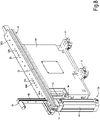
- the machine tool thus configured allows to easily switch from a configuration for machining workpieces that require mechanical clamping by means of the mechanical clamping members 33, to a configuration for machining workpieces that require pneumatic clamping by means of the pneumatic clamping members 51.
- workpieces that require mechanical clamping may be elongated pieces, such as parts of chairs or table legs.
- Workpieces that require pneumatic clamping may be panels or other flat pieces or pieces having flat surfaces of sufficient extension to allow adhesion to suction cups.
- the support and clamping system 21L on the left is set up to work elongated workpieces PA.
- the workpiece PA is curved and is clamped by adjusting the individual mechanical clamping members 33 at variable heights.
- the right support and clamping system 21R is configured to clamp a flat workpiece, such as a panel P-P.
- Fig. 3 which shows the support and clamping system set up for machining elongated workpieces PA
- the pneumatic clamping members 51 of each beam 27 are parked in an area of the respective beam 27 distant from the area in which the respective mechanical clamping member 33 is. In this way, the pneumatic clamping members 51 do not interfere with the working head 9.
- the flat workpiece PP to be machined is clamped by suction through an intermediate suction plane PM, which may be made of material that can be damaged by the working tools of the machine tool 1.
- the intermediate suction plane PM has suction ducts that open onto the upper surface thereof, on which the flat workpiece PP to be machined rests and anchors.
- the channeling made in the intermediate plane PM can be in fluid communication with holes 32A ( Figs. 8 , 10 ), made in the upper surface 28 of each beam 27, through which suction can be carried out.
- each beam 27 can have further holes 32B, e.g., blind and/or threaded holes, for clamping auxiliary equipment (not shown) for clamping pieces of particular shape.
- the respective mechanical clamping members 33 can be brought to the at least partially raised position, so that the guides 43 thereof can be used as positioning stops of the flat workpiece PP to be machined, as shown in Fig. 7 .
- the mechanical clamping members 33 can be lowered and retracted under the upper surfaces 28 of the beams 27. In this way, the flat workpiece PP can be machined along its entire perimeter by means of the relative movements between the working head 9 and the slide 25.
- the mechanical clamping members 33 can be retracted at the level of the upper surface 28 of the beams 27, or under such upper surface. However, this is not strictly necessary. Depending on the height of the pneumatic clamping members 51, in some embodiments it may be sufficient to lower the mechanical clamping members 33, and in particular the upper jaws 39 thereof, until reaching a height sufficiently close to the upper surface 28, such that the tools U carried by the electro-spindles 13 can move around the flat workpiece PP to be machined without bumping against the jaws 37, 39 of the mechanical clamping members 33.
- the mechanical clamping members 33 are preferably positioned at the ends of the beams 27 facing the loading and unloading area
Landscapes
- Engineering & Computer Science (AREA)
- Mechanical Engineering (AREA)
- Life Sciences & Earth Sciences (AREA)
- Wood Science & Technology (AREA)
- Forests & Forestry (AREA)
- Jigs For Machine Tools (AREA)
- Machine Tool Units (AREA)
Applications Claiming Priority (1)
| Application Number | Priority Date | Filing Date | Title |
|---|---|---|---|
| IT102021000008450A IT202100008450A1 (it) | 2021-04-06 | 2021-04-06 | Una macchina utensile con organi a scomparsa per il bloccaggio dei pezzi da lavorare |
Publications (1)
| Publication Number | Publication Date |
|---|---|
| EP4070913A1 true EP4070913A1 (de) | 2022-10-12 |
Family
ID=76523385
Family Applications (1)
| Application Number | Title | Priority Date | Filing Date |
|---|---|---|---|
| EP22166316.4A Pending EP4070913A1 (de) | 2021-04-06 | 2022-04-01 | Werkzeugmaschine mit einziehbaren elementen zum einspannen der zu bearbeitenden werkstücke |
Country Status (3)
| Country | Link |
|---|---|
| US (1) | US20220314381A1 (de) |
| EP (1) | EP4070913A1 (de) |
| IT (1) | IT202100008450A1 (de) |
Cited By (1)
| Publication number | Priority date | Publication date | Assignee | Title |
|---|---|---|---|---|
| IT202200023319A1 (it) | 2022-11-11 | 2024-05-11 | Paolino Bacci Srl | Una macchina utensile con sistema di alimentazione integrato dei pezzi da lavorare |
Families Citing this family (2)
| Publication number | Priority date | Publication date | Assignee | Title |
|---|---|---|---|---|
| WO2025024612A1 (en) * | 2023-07-24 | 2025-01-30 | Durney Max W | Pocket screw and dowel apparatus |
| EP4659921A1 (de) * | 2024-06-04 | 2025-12-10 | SCM Group S.p.A. | Maschine zur bearbeitung eines werkstücks |
Citations (9)
| Publication number | Priority date | Publication date | Assignee | Title |
|---|---|---|---|---|
| EP1075903A2 (de) * | 1999-08-09 | 2001-02-14 | Esserte di Sella, Giovanni | Holzbearbeitungsmaschine zum Verarbeiten von Gegenständen komplexer Form von unterschiedlichen Abmessungen und dazugehöriges Verfahren |
| US20020144751A1 (en) * | 2001-04-06 | 2002-10-10 | Sante Marchioro | Device for the positioning and blocking of pieces on wood working machines and relative machine |
| EP2117790A2 (de) * | 2007-02-07 | 2009-11-18 | Paolino Bacci S.R.L. | Bearbeitungszentrum |
| EP2165811A2 (de) * | 2008-09-17 | 2010-03-24 | Michael Weinig Aktiengesellschaft | Maschine und Verfahren zur Bearbeitung von Werkstücken aus Holz, Kunststoff und dergleichen |
| DE202012104805U1 (de) | 2012-12-10 | 2013-01-04 | Holz-Her Gmbh | Konsolentisch für eine Holzbearbeitungsmaschine |
| US20140015185A1 (en) * | 2012-07-11 | 2014-01-16 | Startechno Co., Ltd. | Work processing apparatus |
| EP2846967A1 (de) | 2012-05-07 | 2015-03-18 | Paolino Bacci S.r.l. | Bearbeitungszentrum für mehrfachbearbeitung |
| EP2991811A1 (de) | 2013-05-03 | 2016-03-09 | Paolino Bacci S.r.l. | Bearbeitungszentrum |
| EP3403793A1 (de) | 2017-05-18 | 2018-11-21 | Paolino Bacci S.R.L. | Werkzeugmaschine mit durch ausrichtbare sauggreifer definierter arbeitsfläche |
Family Cites Families (1)
| Publication number | Priority date | Publication date | Assignee | Title |
|---|---|---|---|---|
| KR101305189B1 (ko) * | 2011-11-07 | 2013-09-12 | 기아자동차주식회사 | 차량용 패널 클램핑 장치 |
-
2021
- 2021-04-06 IT IT102021000008450A patent/IT202100008450A1/it unknown
-
2022
- 2022-04-01 EP EP22166316.4A patent/EP4070913A1/de active Pending
- 2022-04-05 US US17/713,778 patent/US20220314381A1/en not_active Abandoned
Patent Citations (9)
| Publication number | Priority date | Publication date | Assignee | Title |
|---|---|---|---|---|
| EP1075903A2 (de) * | 1999-08-09 | 2001-02-14 | Esserte di Sella, Giovanni | Holzbearbeitungsmaschine zum Verarbeiten von Gegenständen komplexer Form von unterschiedlichen Abmessungen und dazugehöriges Verfahren |
| US20020144751A1 (en) * | 2001-04-06 | 2002-10-10 | Sante Marchioro | Device for the positioning and blocking of pieces on wood working machines and relative machine |
| EP2117790A2 (de) * | 2007-02-07 | 2009-11-18 | Paolino Bacci S.R.L. | Bearbeitungszentrum |
| EP2165811A2 (de) * | 2008-09-17 | 2010-03-24 | Michael Weinig Aktiengesellschaft | Maschine und Verfahren zur Bearbeitung von Werkstücken aus Holz, Kunststoff und dergleichen |
| EP2846967A1 (de) | 2012-05-07 | 2015-03-18 | Paolino Bacci S.r.l. | Bearbeitungszentrum für mehrfachbearbeitung |
| US20140015185A1 (en) * | 2012-07-11 | 2014-01-16 | Startechno Co., Ltd. | Work processing apparatus |
| DE202012104805U1 (de) | 2012-12-10 | 2013-01-04 | Holz-Her Gmbh | Konsolentisch für eine Holzbearbeitungsmaschine |
| EP2991811A1 (de) | 2013-05-03 | 2016-03-09 | Paolino Bacci S.r.l. | Bearbeitungszentrum |
| EP3403793A1 (de) | 2017-05-18 | 2018-11-21 | Paolino Bacci S.R.L. | Werkzeugmaschine mit durch ausrichtbare sauggreifer definierter arbeitsfläche |
Cited By (1)
| Publication number | Priority date | Publication date | Assignee | Title |
|---|---|---|---|---|
| IT202200023319A1 (it) | 2022-11-11 | 2024-05-11 | Paolino Bacci Srl | Una macchina utensile con sistema di alimentazione integrato dei pezzi da lavorare |
Also Published As
| Publication number | Publication date |
|---|---|
| US20220314381A1 (en) | 2022-10-06 |
| IT202100008450A1 (it) | 2022-10-06 |
Similar Documents
| Publication | Publication Date | Title |
|---|---|---|
| EP4070913A1 (de) | Werkzeugmaschine mit einziehbaren elementen zum einspannen der zu bearbeitenden werkstücke | |
| US11897073B2 (en) | Double-station gantry combined processing system for automatically overturning and processing workpieces | |
| US5700117A (en) | Machine tool for machining panels and plates | |
| EP3943228A1 (de) | Horizontales fünf-achsen-plattenumwandlungsbearbeitungszentrum | |
| EP1132171B1 (de) | Werkzeugmaschine zum Bearbeiten von langen Werkstücken | |
| EP2991811B1 (de) | Bearbeitungszentrum | |
| US20190224790A1 (en) | Variable machine table | |
| EP2117790B1 (de) | Bearbeitungszentrum | |
| JPH0442099B2 (de) | ||
| EP1142671A1 (de) | Schleifmaschine mit einem Doppelkolonnensystem | |
| US5004381A (en) | Drilling machine for planar face and/or end face drilling on panel-type workpieces or panel blanks | |
| US7331099B2 (en) | Machine tool and method for the correction or compensation of different tool lengths in a machine tool | |
| KR101806910B1 (ko) | 레이저 가공기용 지그 리프팅 장치 및 이를 포함하는 지그 교체 시스템 | |
| JPS59147780A (ja) | ワ−クの加工装置 | |
| EP3129202B1 (de) | Werkzeugmaschine und modulares system zur bearbeitung produkten aus steinmaterial | |
| EP2944419B1 (de) | Bearbeitungszentrum mit trennbarem werkstückauflagetisch | |
| JPS6045018B2 (ja) | 被加工物の自動送り装置 | |
| EP4491359A1 (de) | Werkzeugmaschine mit verbessertem werkstückladesystem und verfahren dazu | |
| EP4292756A1 (de) | Maschine zur verarbeitung von platten oder dergleichen, insbesondere aus holz oder holzwerkstoffen oder holzwerkstoffen | |
| CN216372580U (zh) | 橱柜上柜自动化生产线 | |
| EP4132754B1 (de) | Anlage zur bearbeitung von werkstücken aus holz, kunststoff, aluminium und dergleichen sowie verfahren zum bearbeiten solcher werkstücke | |
| RU2836246C2 (ru) | Двухпозиционная комбинированная портальная система обработки, способная автоматически переворачивать и обрабатывать заготовки | |
| CN206998317U (zh) | 用于长条工件定位的数控加工中心 | |
| IT202000022525A1 (it) | Centro di lavoro multiasse munito di magazzino-utensili meccanizzato. | |
| SU1183313A1 (ru) | Поточна лини дл обработки изделий |
Legal Events
| Date | Code | Title | Description |
|---|---|---|---|
| PUAI | Public reference made under article 153(3) epc to a published international application that has entered the european phase |
Free format text: ORIGINAL CODE: 0009012 |
|
| STAA | Information on the status of an ep patent application or granted ep patent |
Free format text: STATUS: THE APPLICATION HAS BEEN PUBLISHED |
|
| AK | Designated contracting states |
Kind code of ref document: A1 Designated state(s): AL AT BE BG CH CY CZ DE DK EE ES FI FR GB GR HR HU IE IS IT LI LT LU LV MC MK MT NL NO PL PT RO RS SE SI SK SM TR |
|
| STAA | Information on the status of an ep patent application or granted ep patent |
Free format text: STATUS: REQUEST FOR EXAMINATION WAS MADE |
|
| 17P | Request for examination filed |
Effective date: 20230407 |
|
| RBV | Designated contracting states (corrected) |
Designated state(s): AL AT BE BG CH CY CZ DE DK EE ES FI FR GB GR HR HU IE IS IT LI LT LU LV MC MK MT NL NO PL PT RO RS SE SI SK SM TR |
|
| GRAP | Despatch of communication of intention to grant a patent |
Free format text: ORIGINAL CODE: EPIDOSNIGR1 |
|
| STAA | Information on the status of an ep patent application or granted ep patent |
Free format text: STATUS: GRANT OF PATENT IS INTENDED |
|
| INTG | Intention to grant announced |
Effective date: 20251028 |
|
| GRAS | Grant fee paid |
Free format text: ORIGINAL CODE: EPIDOSNIGR3 |
|
| GRAA | (expected) grant |
Free format text: ORIGINAL CODE: 0009210 |
|
| STAA | Information on the status of an ep patent application or granted ep patent |
Free format text: STATUS: THE PATENT HAS BEEN GRANTED |