EP4070936B1 - Tiefziehverpackungsmaschine mit impulssiegelschienen und impulssiegelverfahren - Google Patents
Tiefziehverpackungsmaschine mit impulssiegelschienen und impulssiegelverfahren Download PDFInfo
- Publication number
- EP4070936B1 EP4070936B1 EP22158977.3A EP22158977A EP4070936B1 EP 4070936 B1 EP4070936 B1 EP 4070936B1 EP 22158977 A EP22158977 A EP 22158977A EP 4070936 B1 EP4070936 B1 EP 4070936B1
- Authority
- EP
- European Patent Office
- Prior art keywords
- sealing
- impulse
- bars
- pair
- tool
- Prior art date
- Legal status (The legal status is an assumption and is not a legal conclusion. Google has not performed a legal analysis and makes no representation as to the accuracy of the status listed.)
- Active
Links
Images

Classifications
-
- B—PERFORMING OPERATIONS; TRANSPORTING
- B65—CONVEYING; PACKING; STORING; HANDLING THIN OR FILAMENTARY MATERIAL
- B65B—MACHINES, APPARATUS OR DEVICES FOR, OR METHODS OF, PACKAGING ARTICLES OR MATERIALS; UNPACKING
- B65B7/00—Closing containers or receptacles after filling
- B65B7/16—Closing semi-rigid or rigid containers or receptacles not deformed by, or not taking-up shape of, contents, e.g. boxes or cartons
- B65B7/162—Closing semi-rigid or rigid containers or receptacles not deformed by, or not taking-up shape of, contents, e.g. boxes or cartons by feeding web material to securing means
- B65B7/164—Securing by heat-sealing
-
- B—PERFORMING OPERATIONS; TRANSPORTING
- B29—WORKING OF PLASTICS; WORKING OF SUBSTANCES IN A PLASTIC STATE IN GENERAL
- B29C—SHAPING OR JOINING OF PLASTICS; SHAPING OF MATERIAL IN A PLASTIC STATE, NOT OTHERWISE PROVIDED FOR; AFTER-TREATMENT OF THE SHAPED PRODUCTS, e.g. REPAIRING
- B29C66/00—General aspects of processes or apparatus for joining preformed parts
- B29C66/70—General aspects of processes or apparatus for joining preformed parts characterised by the composition, physical properties or the structure of the material of the parts to be joined; Joining with non-plastics material
- B29C66/73—General aspects of processes or apparatus for joining preformed parts characterised by the composition, physical properties or the structure of the material of the parts to be joined; Joining with non-plastics material characterised by the intensive physical properties of the material of the parts to be joined, by the optical properties of the material of the parts to be joined, by the extensive physical properties of the parts to be joined, by the state of the material of the parts to be joined or by the material of the parts to be joined being a thermoplastic or a thermoset
- B29C66/739—General aspects of processes or apparatus for joining preformed parts characterised by the composition, physical properties or the structure of the material of the parts to be joined; Joining with non-plastics material characterised by the intensive physical properties of the material of the parts to be joined, by the optical properties of the material of the parts to be joined, by the extensive physical properties of the parts to be joined, by the state of the material of the parts to be joined or by the material of the parts to be joined being a thermoplastic or a thermoset characterised by the material of the parts to be joined being a thermoplastic or a thermoset
- B29C66/7392—General aspects of processes or apparatus for joining preformed parts characterised by the composition, physical properties or the structure of the material of the parts to be joined; Joining with non-plastics material characterised by the intensive physical properties of the material of the parts to be joined, by the optical properties of the material of the parts to be joined, by the extensive physical properties of the parts to be joined, by the state of the material of the parts to be joined or by the material of the parts to be joined being a thermoplastic or a thermoset characterised by the material of the parts to be joined being a thermoplastic or a thermoset characterised by the material of at least one of the parts being a thermoplastic
- B29C66/73921—General aspects of processes or apparatus for joining preformed parts characterised by the composition, physical properties or the structure of the material of the parts to be joined; Joining with non-plastics material characterised by the intensive physical properties of the material of the parts to be joined, by the optical properties of the material of the parts to be joined, by the extensive physical properties of the parts to be joined, by the state of the material of the parts to be joined or by the material of the parts to be joined being a thermoplastic or a thermoset characterised by the material of the parts to be joined being a thermoplastic or a thermoset characterised by the material of at least one of the parts being a thermoplastic characterised by the materials of both parts being thermoplastics
-
- B—PERFORMING OPERATIONS; TRANSPORTING
- B29—WORKING OF PLASTICS; WORKING OF SUBSTANCES IN A PLASTIC STATE IN GENERAL
- B29C—SHAPING OR JOINING OF PLASTICS; SHAPING OF MATERIAL IN A PLASTIC STATE, NOT OTHERWISE PROVIDED FOR; AFTER-TREATMENT OF THE SHAPED PRODUCTS, e.g. REPAIRING
- B29C65/00—Joining or sealing of preformed parts, e.g. welding of plastics materials; Apparatus therefor
- B29C65/02—Joining or sealing of preformed parts, e.g. welding of plastics materials; Apparatus therefor by heating, with or without pressure
- B29C65/18—Joining or sealing of preformed parts, e.g. welding of plastics materials; Apparatus therefor by heating, with or without pressure using heated tools
- B29C65/22—Heated wire resistive ribbon, resistive band or resistive strip
-
- B—PERFORMING OPERATIONS; TRANSPORTING
- B29—WORKING OF PLASTICS; WORKING OF SUBSTANCES IN A PLASTIC STATE IN GENERAL
- B29C—SHAPING OR JOINING OF PLASTICS; SHAPING OF MATERIAL IN A PLASTIC STATE, NOT OTHERWISE PROVIDED FOR; AFTER-TREATMENT OF THE SHAPED PRODUCTS, e.g. REPAIRING
- B29C65/00—Joining or sealing of preformed parts, e.g. welding of plastics materials; Apparatus therefor
- B29C65/02—Joining or sealing of preformed parts, e.g. welding of plastics materials; Apparatus therefor by heating, with or without pressure
- B29C65/38—Impulse heating
-
- B—PERFORMING OPERATIONS; TRANSPORTING
- B29—WORKING OF PLASTICS; WORKING OF SUBSTANCES IN A PLASTIC STATE IN GENERAL
- B29C—SHAPING OR JOINING OF PLASTICS; SHAPING OF MATERIAL IN A PLASTIC STATE, NOT OTHERWISE PROVIDED FOR; AFTER-TREATMENT OF THE SHAPED PRODUCTS, e.g. REPAIRING
- B29C66/00—General aspects of processes or apparatus for joining preformed parts
- B29C66/01—General aspects dealing with the joint area or with the area to be joined
- B29C66/05—Particular design of joint configurations
- B29C66/10—Particular design of joint configurations particular design of the joint cross-sections
- B29C66/11—Joint cross-sections comprising a single joint-segment, i.e. one of the parts to be joined comprising a single joint-segment in the joint cross-section
- B29C66/112—Single lapped joints
-
- B—PERFORMING OPERATIONS; TRANSPORTING
- B29—WORKING OF PLASTICS; WORKING OF SUBSTANCES IN A PLASTIC STATE IN GENERAL
- B29C—SHAPING OR JOINING OF PLASTICS; SHAPING OF MATERIAL IN A PLASTIC STATE, NOT OTHERWISE PROVIDED FOR; AFTER-TREATMENT OF THE SHAPED PRODUCTS, e.g. REPAIRING
- B29C66/00—General aspects of processes or apparatus for joining preformed parts
- B29C66/01—General aspects dealing with the joint area or with the area to be joined
- B29C66/05—Particular design of joint configurations
- B29C66/10—Particular design of joint configurations particular design of the joint cross-sections
- B29C66/13—Single flanged joints; Fin-type joints; Single hem joints; Edge joints; Interpenetrating fingered joints; Other specific particular designs of joint cross-sections not provided for in groups B29C66/11 - B29C66/12
- B29C66/131—Single flanged joints, i.e. one of the parts to be joined being rigid and flanged in the joint area
-
- B—PERFORMING OPERATIONS; TRANSPORTING
- B29—WORKING OF PLASTICS; WORKING OF SUBSTANCES IN A PLASTIC STATE IN GENERAL
- B29C—SHAPING OR JOINING OF PLASTICS; SHAPING OF MATERIAL IN A PLASTIC STATE, NOT OTHERWISE PROVIDED FOR; AFTER-TREATMENT OF THE SHAPED PRODUCTS, e.g. REPAIRING
- B29C66/00—General aspects of processes or apparatus for joining preformed parts
- B29C66/01—General aspects dealing with the joint area or with the area to be joined
- B29C66/05—Particular design of joint configurations
- B29C66/20—Particular design of joint configurations particular design of the joint lines, e.g. of the weld lines
- B29C66/23—Particular design of joint configurations particular design of the joint lines, e.g. of the weld lines said joint lines being multiple and parallel or being in the form of tessellations
- B29C66/232—Particular design of joint configurations particular design of the joint lines, e.g. of the weld lines said joint lines being multiple and parallel or being in the form of tessellations said joint lines being multiple and parallel, i.e. the joint being formed by several parallel joint lines
-
- B—PERFORMING OPERATIONS; TRANSPORTING
- B29—WORKING OF PLASTICS; WORKING OF SUBSTANCES IN A PLASTIC STATE IN GENERAL
- B29C—SHAPING OR JOINING OF PLASTICS; SHAPING OF MATERIAL IN A PLASTIC STATE, NOT OTHERWISE PROVIDED FOR; AFTER-TREATMENT OF THE SHAPED PRODUCTS, e.g. REPAIRING
- B29C66/00—General aspects of processes or apparatus for joining preformed parts
- B29C66/01—General aspects dealing with the joint area or with the area to be joined
- B29C66/05—Particular design of joint configurations
- B29C66/20—Particular design of joint configurations particular design of the joint lines, e.g. of the weld lines
- B29C66/24—Particular design of joint configurations particular design of the joint lines, e.g. of the weld lines said joint lines being closed or non-straight
- B29C66/242—Particular design of joint configurations particular design of the joint lines, e.g. of the weld lines said joint lines being closed or non-straight said joint lines being closed, i.e. forming closed contours
- B29C66/2424—Particular design of joint configurations particular design of the joint lines, e.g. of the weld lines said joint lines being closed or non-straight said joint lines being closed, i.e. forming closed contours being a closed polygonal chain
- B29C66/24243—Particular design of joint configurations particular design of the joint lines, e.g. of the weld lines said joint lines being closed or non-straight said joint lines being closed, i.e. forming closed contours being a closed polygonal chain forming a quadrilateral
- B29C66/24244—Particular design of joint configurations particular design of the joint lines, e.g. of the weld lines said joint lines being closed or non-straight said joint lines being closed, i.e. forming closed contours being a closed polygonal chain forming a quadrilateral forming a rectangle
-
- B—PERFORMING OPERATIONS; TRANSPORTING
- B29—WORKING OF PLASTICS; WORKING OF SUBSTANCES IN A PLASTIC STATE IN GENERAL
- B29C—SHAPING OR JOINING OF PLASTICS; SHAPING OF MATERIAL IN A PLASTIC STATE, NOT OTHERWISE PROVIDED FOR; AFTER-TREATMENT OF THE SHAPED PRODUCTS, e.g. REPAIRING
- B29C66/00—General aspects of processes or apparatus for joining preformed parts
- B29C66/01—General aspects dealing with the joint area or with the area to be joined
- B29C66/345—Progressively making the joint, e.g. starting from the middle
- B29C66/3452—Making complete joints by combining partial joints
-
- B—PERFORMING OPERATIONS; TRANSPORTING
- B29—WORKING OF PLASTICS; WORKING OF SUBSTANCES IN A PLASTIC STATE IN GENERAL
- B29C—SHAPING OR JOINING OF PLASTICS; SHAPING OF MATERIAL IN A PLASTIC STATE, NOT OTHERWISE PROVIDED FOR; AFTER-TREATMENT OF THE SHAPED PRODUCTS, e.g. REPAIRING
- B29C66/00—General aspects of processes or apparatus for joining preformed parts
- B29C66/50—General aspects of joining tubular articles; General aspects of joining long products, i.e. bars or profiled elements; General aspects of joining single elements to tubular articles, hollow articles or bars; General aspects of joining several hollow-preforms to form hollow or tubular articles
- B29C66/51—Joining tubular articles, profiled elements or bars; Joining single elements to tubular articles, hollow articles or bars; Joining several hollow-preforms to form hollow or tubular articles
- B29C66/53—Joining single elements to tubular articles, hollow articles or bars
- B29C66/534—Joining single elements to open ends of tubular or hollow articles or to the ends of bars
- B29C66/5346—Joining single elements to open ends of tubular or hollow articles or to the ends of bars said single elements being substantially flat
- B29C66/53461—Joining single elements to open ends of tubular or hollow articles or to the ends of bars said single elements being substantially flat joining substantially flat covers and/or substantially flat bottoms to open ends of container bodies
-
- B—PERFORMING OPERATIONS; TRANSPORTING
- B29—WORKING OF PLASTICS; WORKING OF SUBSTANCES IN A PLASTIC STATE IN GENERAL
- B29C—SHAPING OR JOINING OF PLASTICS; SHAPING OF MATERIAL IN A PLASTIC STATE, NOT OTHERWISE PROVIDED FOR; AFTER-TREATMENT OF THE SHAPED PRODUCTS, e.g. REPAIRING
- B29C66/00—General aspects of processes or apparatus for joining preformed parts
- B29C66/80—General aspects of machine operations or constructions and parts thereof
- B29C66/81—General aspects of the pressing elements, i.e. the elements applying pressure on the parts to be joined in the area to be joined, e.g. the welding jaws or clamps
- B29C66/814—General aspects of the pressing elements, i.e. the elements applying pressure on the parts to be joined in the area to be joined, e.g. the welding jaws or clamps characterised by the design of the pressing elements, e.g. of the welding jaws or clamps
- B29C66/8145—General aspects of the pressing elements, i.e. the elements applying pressure on the parts to be joined in the area to be joined, e.g. the welding jaws or clamps characterised by the design of the pressing elements, e.g. of the welding jaws or clamps characterised by the constructional aspects of the pressing elements, e.g. of the welding jaws or clamps
- B29C66/81463—General aspects of the pressing elements, i.e. the elements applying pressure on the parts to be joined in the area to be joined, e.g. the welding jaws or clamps characterised by the design of the pressing elements, e.g. of the welding jaws or clamps characterised by the constructional aspects of the pressing elements, e.g. of the welding jaws or clamps comprising a plurality of single pressing elements, e.g. a plurality of sonotrodes, or comprising a plurality of single counter-pressing elements, e.g. a plurality of anvils, said plurality of said single elements being suitable for making a single joint
- B29C66/81465—General aspects of the pressing elements, i.e. the elements applying pressure on the parts to be joined in the area to be joined, e.g. the welding jaws or clamps characterised by the design of the pressing elements, e.g. of the welding jaws or clamps characterised by the constructional aspects of the pressing elements, e.g. of the welding jaws or clamps comprising a plurality of single pressing elements, e.g. a plurality of sonotrodes, or comprising a plurality of single counter-pressing elements, e.g. a plurality of anvils, said plurality of said single elements being suitable for making a single joint one placed behind the other in a single row in the feed direction
-
- B—PERFORMING OPERATIONS; TRANSPORTING
- B29—WORKING OF PLASTICS; WORKING OF SUBSTANCES IN A PLASTIC STATE IN GENERAL
- B29C—SHAPING OR JOINING OF PLASTICS; SHAPING OF MATERIAL IN A PLASTIC STATE, NOT OTHERWISE PROVIDED FOR; AFTER-TREATMENT OF THE SHAPED PRODUCTS, e.g. REPAIRING
- B29C66/00—General aspects of processes or apparatus for joining preformed parts
- B29C66/80—General aspects of machine operations or constructions and parts thereof
- B29C66/83—General aspects of machine operations or constructions and parts thereof characterised by the movement of the joining or pressing tools
- B29C66/832—Reciprocating joining or pressing tools
- B29C66/8322—Joining or pressing tools reciprocating along one axis
-
- B—PERFORMING OPERATIONS; TRANSPORTING
- B29—WORKING OF PLASTICS; WORKING OF SUBSTANCES IN A PLASTIC STATE IN GENERAL
- B29C—SHAPING OR JOINING OF PLASTICS; SHAPING OF MATERIAL IN A PLASTIC STATE, NOT OTHERWISE PROVIDED FOR; AFTER-TREATMENT OF THE SHAPED PRODUCTS, e.g. REPAIRING
- B29C66/00—General aspects of processes or apparatus for joining preformed parts
- B29C66/80—General aspects of machine operations or constructions and parts thereof
- B29C66/84—Specific machine types or machines suitable for specific applications
- B29C66/843—Machines for making separate joints at the same time in different planes; Machines for making separate joints at the same time mounted in parallel or in series
- B29C66/8432—Machines for making separate joints at the same time mounted in parallel or in series
-
- B—PERFORMING OPERATIONS; TRANSPORTING
- B65—CONVEYING; PACKING; STORING; HANDLING THIN OR FILAMENTARY MATERIAL
- B65B—MACHINES, APPARATUS OR DEVICES FOR, OR METHODS OF, PACKAGING ARTICLES OR MATERIALS; UNPACKING
- B65B43/00—Forming, feeding, opening or setting-up containers or receptacles in association with packaging
- B65B43/08—Forming three-dimensional [3D] containers from sheet material
-
- B—PERFORMING OPERATIONS; TRANSPORTING
- B65—CONVEYING; PACKING; STORING; HANDLING THIN OR FILAMENTARY MATERIAL
- B65B—MACHINES, APPARATUS OR DEVICES FOR, OR METHODS OF, PACKAGING ARTICLES OR MATERIALS; UNPACKING
- B65B51/00—Devices for, or methods of, sealing or securing package folds or closures; Devices for gathering or twisting wrappers, or necks of bags
- B65B51/10—Applying or generating heat or pressure or combinations thereof
- B65B51/14—Applying or generating heat or pressure or combinations thereof by reciprocating or oscillating members
-
- B—PERFORMING OPERATIONS; TRANSPORTING
- B65—CONVEYING; PACKING; STORING; HANDLING THIN OR FILAMENTARY MATERIAL
- B65B—MACHINES, APPARATUS OR DEVICES FOR, OR METHODS OF, PACKAGING ARTICLES OR MATERIALS; UNPACKING
- B65B51/00—Devices for, or methods of, sealing or securing package folds or closures; Devices for gathering or twisting wrappers, or necks of bags
- B65B51/10—Applying or generating heat or pressure or combinations thereof
- B65B51/26—Devices specially adapted for producing transverse or longitudinal seams in webs or tubes
-
- B—PERFORMING OPERATIONS; TRANSPORTING
- B65—CONVEYING; PACKING; STORING; HANDLING THIN OR FILAMENTARY MATERIAL
- B65B—MACHINES, APPARATUS OR DEVICES FOR, OR METHODS OF, PACKAGING ARTICLES OR MATERIALS; UNPACKING
- B65B61/00—Auxiliary devices, not otherwise provided for, for operating on sheets, blanks, webs, binding material, containers or packages
- B65B61/04—Auxiliary devices, not otherwise provided for, for operating on sheets, blanks, webs, binding material, containers or packages for severing webs, or for separating joined packages
- B65B61/06—Auxiliary devices, not otherwise provided for, for operating on sheets, blanks, webs, binding material, containers or packages for severing webs, or for separating joined packages by cutting
-
- B—PERFORMING OPERATIONS; TRANSPORTING
- B65—CONVEYING; PACKING; STORING; HANDLING THIN OR FILAMENTARY MATERIAL
- B65B—MACHINES, APPARATUS OR DEVICES FOR, OR METHODS OF, PACKAGING ARTICLES OR MATERIALS; UNPACKING
- B65B9/00—Enclosing successive articles, or quantities of material, e.g. liquids or semiliquids, in flat, folded, or tubular webs of flexible sheet material; Subdividing filled flexible tubes to form packages
- B65B9/02—Enclosing successive articles, or quantities of material between opposed webs
- B65B9/04—Enclosing successive articles, or quantities of material between opposed webs one or both webs being formed with pockets for the reception of the articles, or of the quantities of material
-
- B—PERFORMING OPERATIONS; TRANSPORTING
- B29—WORKING OF PLASTICS; WORKING OF SUBSTANCES IN A PLASTIC STATE IN GENERAL
- B29C—SHAPING OR JOINING OF PLASTICS; SHAPING OF MATERIAL IN A PLASTIC STATE, NOT OTHERWISE PROVIDED FOR; AFTER-TREATMENT OF THE SHAPED PRODUCTS, e.g. REPAIRING
- B29C65/00—Joining or sealing of preformed parts, e.g. welding of plastics materials; Apparatus therefor
- B29C65/02—Joining or sealing of preformed parts, e.g. welding of plastics materials; Apparatus therefor by heating, with or without pressure
- B29C65/18—Joining or sealing of preformed parts, e.g. welding of plastics materials; Apparatus therefor by heating, with or without pressure using heated tools
- B29C65/22—Heated wire resistive ribbon, resistive band or resistive strip
- B29C65/221—Heated wire resistive ribbon, resistive band or resistive strip characterised by the type of heated wire, resistive ribbon, band or strip
- B29C65/224—Heated wire resistive ribbon, resistive band or resistive strip characterised by the type of heated wire, resistive ribbon, band or strip being a resistive ribbon, a resistive band or a resistive strip
-
- B—PERFORMING OPERATIONS; TRANSPORTING
- B29—WORKING OF PLASTICS; WORKING OF SUBSTANCES IN A PLASTIC STATE IN GENERAL
- B29L—INDEXING SCHEME ASSOCIATED WITH SUBCLASS B29C, RELATING TO PARTICULAR ARTICLES
- B29L2031/00—Other particular articles
- B29L2031/712—Containers; Packaging elements or accessories, Packages
- B29L2031/7162—Boxes, cartons, cases
- B29L2031/7164—Blister packages
Definitions
- the present invention relates to a thermoforming packaging machine according to claim 1. Furthermore, the present invention relates to a method for closing packaging trays according to claim 9.
- DE 198 15 763 C2 discloses an impulse sealing bar comprising an energizable heating band. Thermal insulation is provided between a bar body and the heating band. The impulse sealing bar is pressed firmly onto the films to be sealed, while the heating band is subjected to a current pulse via a pulse generator, thereby heating it to seal the films together.
- a pulse heating device comprising a metal carrier on which an electrically insulating layer is applied, to which at least one thick-film conductor track is attached as a heating conductor.
- the electrical resistance of the heating conductor which varies depending on the current heating conductor temperature, is measured and used as a control variable for the current supply.
- DE 10 2012 007 594 B1 and DE 10 2012 007 598 A1 disclose a packaging machine with a pre-sealing station for producing a pre-sealing seam and a main sealing station downstream in the direction of production for producing a main sealing seam, wherein the pre-sealing seam together with the main sealing seam result in a closed sealing seam on a finished package.
- US 5 096 052 A discloses a tray closing device with sealing stations arranged one behind the other in the production direction, each comprising a sealing bar for sealing a lidding film onto a tray part positioned underneath.
- US 5,345,747 A discloses a tray sealing device comprising a first sealing tool with ultrasonic transducers and associated counterpressure rollers for sealing a lidding film along opposite edges of a tray part. Furthermore, the tray sealing device has via a second sealing tool with ultrasonic transducers and correspondingly arranged counterpressure rollers to seal the lidding film along the remaining, opposite sides of the tray part. The tray part is transported in a first direction through the first sealing tool and in a second direction perpendicular to the first direction through the second sealing tool.
- the seals of conventional, permanently heated sealing tools are still warm and mechanically unloadable once the sealing tool is opened. This occurs particularly with mono-material films such as PE or HDPE.
- the weight of the product acts on the still-warm, non-dimensionally stable seals, negatively impacting the seal quality. This can even lead to the desired barrier properties of the packaging no longer being met.
- the object of the invention is to provide a thermoforming packaging machine that improves the sealing process both economically and qualitatively. Furthermore, a corresponding method for a thermoforming packaging machine is to be provided.
- thermoforming packaging machine according to claim 1. Furthermore, this object is achieved by means of a method on a thermoforming packaging machine according to claim 9.
- thermoforming packaging machine comprises, in the production direction, a forming station for producing cavities in a film web, an insertion section for filling the cavities with a product, a sealing device for sealing the cavities with a top film, and a cutting device for separating finished packages.
- the sealing device comprises a first sealing tool for a first sealing cycle and a second sealing tool for a second sealing cycle.
- the first sealing tool comprises at least one first pair of impulse sealing bars, aligned in a first orientation relative to the production direction, for producing first seal seam sections
- the second sealing tool comprises at least one second pair of impulse sealing bars, aligned in a second orientation relative to the production direction, for producing second seal seam sections.
- the impulse sealing bars can be integrated in a compact design within the sealing station of the thermoforming packaging machine.
- the impulse sealing bars offer the key advantage that they can be alternately heated and cooled quickly, so that they can be controlled in an energy-efficient manner to produce the seal seams. This property can be excellently integrated into the intermittent operation of the thermoforming packaging machine.
- due to the rapid cooling capacity of the impulse sealing bars they are predestined for forming very thin, delicate seal seams.
- the impulse sealing bars used in the invention unlike conventional sealing tools, do not need to be heated continuously.
- the impulse sealing bars according to the invention are supplied with a current pulse for a fraction of a second, thereby heating them to a desired sealing temperature.
- An interruption The current supply allows the impulse sealing bars to quickly cool to the desired temperature level. This intermittent current supply to the impulse sealing bars enables an energy-efficient sealing process.
- the use of impulse sealing bars offers the advantage of gentle material sealing, with seal seams that can withstand mechanical stress immediately after the sealing process, especially when packaging sensitive products, such as medical devices.
- the paired division of the impulse sealing bars provided in the thermoforming packaging machine according to the invention allows sealing forces and sealing times, for example for the production of longitudinal and transverse seals, to be distributed across different sealing work cycles in such a way that the resulting closed seals can be produced more precisely.
- the provision of separate pairs of impulse sealing bars for different sealing cycles enables better force distribution along the sealing device and thus gentle film welding, which overall leads to very high-quality seal seam production.
- one of the impulse sealing bars used according to the invention is a sealing bar with a resistance-heatable heating conductor, which can be heated intermittently to a desired sealing temperature by means of a current pulse applied to it for a fraction of a second or for a few seconds.
- the current pulse can be generated by a pulse generator.
- the respective impulse sealing bars have at least one electrical heating conductor, which can be designed, for example, as a heating band or a heating wire.
- the heating conductor can be pressed onto the films to be welded during the sealing process. Due to its electrical resistance, the heating conductor can be heated to a predetermined sealing temperature by a current pulse applied to it per sealing cycle during operation of the sealing device. Between the current pulses, i.e., during respective interruptions in the power supply to the heating conductor, the heating conductor cools to a temperature level until another current pulse is applied to it in the subsequent sealing cycle, whereby the heating conductor heats up again to the sealing temperature level.
- the respective impulse sealing bars comprise a bar body and an insulating layer arranged between the bar body and the heating conductor.
- the insulating layer can at least largely prevent the heat energy generated at the heating conductor from is transferred to other components of the impulse sealing rails, for example to the rail body, which could potentially reduce the sealing performance of the heating conductor.
- the sealing device comprises at least one pulse generator for each of the first sealing tool and the second sealing tool, which is designed to generate current pulses for the respective sealing cycles during operation of the sealing device in order to heat the respective heating conductors of the impulse sealing bars of the two sealing tools.
- two identically designed sealing bars can be controlled in parallel with one pulse generator.
- first sealing tool and the second sealing tool are arranged one behind the other in the direction of production, separately, or as an integral unit.
- a separate design of the first and second sealing tools would have the advantage that they can be moved and/or controlled independently of one another. This may favor sensor-controlled operation of the thermoforming packaging machine, as it allows the respective work cycles to be better coordinated.
- the integral version of the first and second sealing tools offers particular advantages for a compact design.
- the first sealing tool and the second sealing tool can perform sealing steps at different times and locations.
- the resulting sealing seams together form a closed sealing seam on the respective packages.
- This allows the respective sealing seams of individual packages to be created step by step along the thermoforming packaging machine, so that the sealing forces required to create the respective sealing seams can be distributed across multiple stations along the thermoforming packaging machine.
- This also promotes gentle welding of the packaging films, which is particularly advantageous when packaging delicate products and using sensitive monofilms, for example, when packaging medical products.
- the first sealing tool is configured to produce, by means of the first pair of impulse sealing bars, first sealing seam sections lying opposite one another on the respective packages during the first sealing cycle
- the second sealing tool is configured to produce, by means of the second pair of impulse sealing bars, second sealing seam sections lying opposite one another on the respective packages during the second sealing cycle following the first.
- the production of the respective opposing sealing seams on a respective package can be carried out in subsequent sealing cycles, in particular at sealing stations arranged one after the other in the direction of production.
- the first pair of impulse sealing bars are aligned transversely to the production direction, and the second pair of impulse sealing bars are aligned in the production direction.
- sealing seams can thus be created multiple times and in different orientations.
- both sealing seams in the production direction and sealing seams orthogonal to the production direction can be produced in stages.
- first pair of impulse sealing bars and the second pair of impulse sealing bars are dimensioned such that at least the respective ends of the first and second sealing seam sections produced thereby overlap. This can ensure that the respective first and second sealing seam sections together create a closed seal of the packaging films on the respective packages along their edges.
- first pair of impulse sealing bars and the second pair of impulse sealing bars are dimensioned such that the first and second sealing seam sections produced thereby extend at least partially beyond their converging ends, whereby the film web is connected to the upper film outside the respective packages produced for improved further and/or removal transport.
- the first pair of impulse sealing bars is preferably designed to simultaneously produce the first sealing seam sections on a package and/or on adjacent packages during the first sealing cycle. This ensures that the first sealing tool, with the impulse sealing bars formed thereon, can produce one or more parallel sealing seams on a package simultaneously. This offers particular advantages on a thermoforming packaging machine used for a multi-lane production process.
- An advantageous embodiment provides that the second pair of impulse sealing bars is configured to simultaneously produce the second sealing seam sections on a package and/or on adjacent packages during the second sealing cycle. This ensures that the second sealing tool, with the impulse sealing bars configured thereon, can produce one or more parallel sealing seams on a package simultaneously. This offers particular advantages on a thermoforming packaging machine used for a multi-lane production process.
- the first pair of impulse sealing bars and/or the second pair of impulse sealing bars are configured to produce straight, possibly slightly curved or wavy, first and/or second sealing seam sections.
- the straight sealing seams thus produced by the first and second sealing cycles can, together, result in a closed sealing seam on a package.
- the result of such combined sealing seams is visually and qualitatively flawless.
- the respective impulse sealing bars can be in the form of straight sealing strips, in particular, rod-shaped.
- thermoforming packaging machine It is possible to perform an evacuation and/or gassing process on the thermoforming packaging machine to create a desired atmosphere within the produced packages. To achieve this, it would be advantageous if all sealing seams aligned transversely to the production direction were first created during the first sealing cycle. Subsequently, an evacuation process and/or gassing using a desired protective gas could take place over unsealed edge areas of the packages. Following this atmosphere exchange, all sealing seams aligned in the production direction can be created during the second sealing cycle.
- the respective impulse sealing bars have contact tips for heating and/or supply lines at their ends. These contact tips can be an interference contour for the sealing process, as they penetrate the sealing plane when the respective impulse sealing bars are pressed against the film material, thereby placing additional stress on the packaging films.
- the film web and/or the top film provide prefabricated recesses for the contact tips. Such recesses could alternatively be produced along the thermoforming packaging machine before the sealing process in the film web and/or top film in order to accommodate the contact tips of the impulse sealing bars during the sealing process.
- the forming station for producing the troughs could also be designed to produce such shapes and/or for a separate forming station to be arranged for this purpose on the thermoforming packaging machine.
- the shapes are located, in particular, outside the packaging to be produced, e.g., in the area of the waste strips (e.g., along an edge or center strip). It is conceivable that the shapes are at least partially cut and/or punched out.
- the respective impulse sealing bars are connected to a liquid cooling system of the thermoforming packaging machine.
- the liquid cooling system can be used as a central unit for cooling several workstations of the thermoforming packaging machine in order to to continuously and/or temporarily cool the tools used, for example, the two sealing tools, during the packaging process. It is conceivable that the liquid cooling system is formed, at least in sections, in a receptacle of the first and/or second sealing tool.
- the respective impulse sealing bars are each secured by means of a fixed, floating bearing. This compensates for thermal expansion of the impulse sealing bars during the heating process. In other words, it prevents mechanical stresses from developing in the impulse sealing bars.
- the invention further relates to a method on a thermoforming packaging machine for sealing cavities formed in a film web to a top film, wherein the cavities are fed in the production direction to a sealing device having a first sealing tool for a first sealing cycle and a second, downstream sealing tool for a subsequent second sealing cycle.
- the first sealing tool uses at least one first pair of impulse sealing bars, aligned in a first orientation relative to the production direction, to produce first seal seam sections
- the second sealing tool uses at least one second pair of impulse sealing bars, aligned in a second orientation relative to the production direction, to produce second seal seam sections.
- the production of the respective sealing seams for the packaging produced along the thermoforming packaging machine can be divided into a first and a second sealing cycle by means of the two pairs of impulse sealing bars, whereby the sealing forces required to produce the sealing seams can also be distributed between the respective sealing cycles, so that overall, qualitatively improved sealing seams can be produced using the two pairs of impulse sealing bars.
- the use of impulse sealing bars for sealing individual packages on the thermoforming packaging machine is energy-efficient and can be carried out in a compact manner.
- An advantageous embodiment provides that, to produce a closed seal seam, the first sealing tool uses the first pair of impulse sealing bars to produce opposing first seal seam sections on the respective packages during the first sealing cycle, and the second sealing tool uses the second pair of impulse sealing bars to produce opposing second seal seam sections on the aforementioned respective packages during the second sealing cycle.
- the first sealing cycle serves as a pre-sealing cycle and the second sealing cycle serves as the main sealing cycle in order to produce closed seal seams on the respective packages.
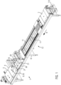
- FIG. 1 shows a perspective view of an intermittently operating thermoforming packaging machine 1 according to the invention.
- the thermoforming packaging machine 1 has a forming station 2, a sealing device 3, a cross-cutting device 4, and a longitudinal cutting device 5, which are arranged in this order in a production direction R on a machine frame 6.
- a feed roller 7 is located on the machine frame 6, from which a film web 8 is drawn.
- the thermoforming packaging machine 1 has a transport chain 11 that grips the film web 8 and transports it further in the production direction R, in particular transport chains or clamp chains 11 arranged on both sides.
- the forming station 2 is designed as a deep-drawing station, in which depressions M (see Figure 2 ) are formed.
- the forming station 2 can be designed in such a way that in the direction perpendicular to the production direction R, several troughs M are formed next to one another.
- an insertion section 12 is provided in which the troughs M formed in the film web 8 are filled with products.
- the sealing device 3 has a hermetically sealable chamber 3a in which the atmosphere in the troughs M can be evacuated, e.g., and/or replaced by gas purging with a replacement gas or with a gas mixture, before producing closed sealing seams with the upper films 10 released from an upper film holder 9.
- the cross-cutting device 4 can be designed as a punch that cuts the film web 8 and the top film 10 in a direction transverse to the production direction R between adjacent troughs M.
- the cross-cutting device 4 operates in such a way that the film web 8 is not cut across its entire width, but rather remains uncut at least in one edge area. This enables controlled further transport through the transport chain 11.
- the longitudinal cutting device 5 can be designed as a knife arrangement with which the film web 8 and the upper film 10 are severed between adjacent troughs M and at the lateral edge of the film web 8 in the production direction R, so that individual packages are present behind the longitudinal cutting device 5.
- thermoforming packaging machine 1 also has a controller 19. Its task is to control and monitor the processes taking place in the thermoforming packaging machine 1.
- a display device 20 with operating elements 21 serves to visualize or influence the process sequences in the thermoforming packaging machine 1 for or by an operator.
- FIG 2 shows a schematic representation of the sealing device 3 with a first sealing tool 13 and a second sealing tool 14, which are arranged one after the other in this order in the production direction R on the thermoforming packaging machine 1.
- the first sealing tool 13 is used during a first sealing cycle S1 and the second sealing tool 14 during a second sealing cycle S2.
- the first sealing tool 13 has a first pair of impulse sealing bars 15A, 15B, which are aligned transversely relative to the production direction R, for producing first sealing seam sections A, which in Figure 2 with respect to the production direction R as transverse sealing seams.
- the second sealing tool 14 has a second pair of impulse sealing rails 16A, 16B aligned in the production direction R for producing second sealing seam sections B.
- the first and second sealing seam sections A, B can together produce a closed sealing seam S.
- the respective impulse sealing rails 15A, 15B each have two impulse sealing bars that run parallel and close to each other.
- the impulse sealing rail 15A is Figure 2 designed for the simultaneous production of adjacent sealing seam sections A on adjacent troughs M. This also applies analogously to the impulse sealing rail 15B of the first sealing tool 13.
- the impulse sealing rails 16A, 16B arranged downstream in the production direction R produce the longitudinal sealing seams on the respective packages in the production direction R.
- the second pair of impulse sealing rails 16A, 16B have a total of four impulse sealing bars arranged parallel in the production direction R, which are designed to produce the second sealing seam sections B along the production direction R.
Landscapes
- Engineering & Computer Science (AREA)
- Mechanical Engineering (AREA)
- Containers And Plastic Fillers For Packaging (AREA)
- Package Closures (AREA)
Description
- Die vorliegende Erfindung bezieht sich auf eine Tiefziehverpackungsmaschine nach Anspruch 1. Ferner betrifft die vorliegende Erfindung ein Verfahren zum Verschließen von Verpackungsmulden gemäß Anspruch 9.
- Es gibt bereits Schlauchbeutelmaschinen und Kammerbandmaschinen, die mittels einer Impulssiegelschiene eine Siegelnaht zum Verschließen einer offenen Seite von zugeführten Verpackungen herstellen. Eine solche Impulssiegelschiene ist beispielsweise aus der
EP 2 505 340 A1 bekannt. -
DE 198 15 763 C2 offenbart eine Impulssiegelschiene, die ein bestrombares Heizband umfasst. Zwischen einem Schienenkörper und dem Heizband ist eine thermische Isolation vorgesehen. Die Impulssiegelschiene wird fest auf die zu verschweißenden Folien gedrückt, während das Heizband über einen Impulsgeber mit einem Stromimpuls beaufschlagt und dadurch aufgeheizt wird, um die Folien miteinander zu verschweißen. -
DE 197 37 471 C2 offenbart eine Impulsheizeinrichtung mit einem Träger aus Metall, auf dem eine elektrisch isolierende Schicht aufgebracht ist, auf welcher mindestens eine Dickschichtleiterbahn als Heizleiter befestigt ist. Zur Bestromung der Impulsheizeinrichtung wird der sich in Abhängigkeit von der momentanen Heizleitertemperatur variierende elektrische Widerstand des Heizleiters gemessen und als Regelgröße für die Bestromung eingesetzt. -
DE 10 2012 007 594 B1 undDE 10 2012 007 598 A1 offenbaren eine Verpackungsmaschine mit einer Vorsiegelstation zum Herstellen einer Vorsiegelnaht sowie eine in Produktionsrichtung nachgelagerte Hauptsiegelstation zum Herstellen einer Hauptsiegelnaht, wobei die Vorsiegelnaht zusammen mit der Hauptsiegelnaht an einer fertig hergestellten Verpackung eine geschlossene Siegelnaht ergeben. -
US 5 096 052 A offenbart eine Schalenverschließvorrichtung mit in Produktionsrichtung hintereinander angeordneten Siegelstationen, die jeweils eine Siegelschiene umfassen, um eine Deckelfolie auf ein darunter positioniertes Schalenteil zu versiegeln. -
US 5 345 747 A offenbart eine Schalenverschließvorrichtung, die ein erstes Siegelwerkzeug mit Ultraschallgebern und diesen zugeordneten Gegendruckrollen umfasst, um eine Deckelfolie entlang gegenüberliegender Ränder eines Schalenteils zu versiegeln. Ferner verfügt die Schalenverschließvorrichtung über ein zweites Siegelwerkzeug mit Ultraschallgebern und diesbezüglich angeordneten Gegendruckrollen, um die Deckelfolie entlang der übrigen, gegenüberliegenden Seiten des Schalenteils zu versiegeln. Das Schalenteil wird in einer ersten Richtung durch das erste Siegelwerkzeug und in einer quer zur ersten Richtung verlaufenden, zweiten Richtung durch das zweite Siegelwerkzeug transportiert. - Oft sind die Siegelnähte bei konventionellem dauerbeheiztem Siegelwerkzeug noch warm und mechanisch nicht belastbar, sobald das Siegelwerkzeug geöffnet wird. Dies tritt vor allem bei Mono-Material Folien wie beispielsweise PE oder HDPE auf. Das Gewicht des Produktes wirkt auf die noch warmen nicht formstabilen Siegelnähte und beeinflusst die Siegelnahtqualität im negativen Sinne. Dies kann sogar dazu führen, dass die gewünschten Barriereeigenschaften der Verpackung nicht mehr gegeben sind.
- Aufgabe der Erfindung ist es, eine Tiefziehverpackungsmaschine zur Verfügung zu stellen, die sowohl in wirtschaftlicher als auch in qualitativer Hinsicht den Siegelvorgang verbessert. Außerdem soll ein dementsprechendes Verfahren an einer Tiefziehverpackungsmaschine bereitgestellt werden.
- Diese Aufgabe wird gelöst mittels einer Tiefziehverpackungsmaschine gemäß dem Anspruch 1. Ferner wird diese Aufgabe gelöst mittels eines Verfahrens an einer Tiefziehverpackungsmaschine gemäß dem Anspruch 9.
- Vorteilhafte Weiterbildungen der Erfindung sind durch die jeweiligen Gegenstände der Unteransprüche gegeben.
- Die erfindungsgemäße Tiefziehverpackungsmaschine weist in Produktionsrichtung eine Formstation zum Herstellen von Mulden in einer Folienbahn, eine Einlegestrecke zum Befüllen der Mulden mit einem Produkt, eine Siegeleinrichtung zum Versiegeln der Mulden mit einer Oberfolie, sowie eine Schneideinrichtung zum Vereinzeln fertig hergestellter Verpackungen auf. Die Siegeleinrichtung umfasst ein erstes Siegelwerkzeug für einen ersten Siegeltakt und ein zweites Siegelwerkzeug für einen zweiten Siegeltakt.
- Erfindungsgemäß umfasst das erste Siegelwerkzeug mindestens ein relativ zur Produktionsrichtung in einer ersten Ausrichtung ausgerichtetes erstes Paar Impulssiegelschienen zum Erzeugen erster Siegelnahtabschnitte und das zweite Siegelwerkzeug mindestens ein relativ zur Produktionsrichtung in einer zweiten Ausrichtung ausgerichtetes zweites Paar Impulssiegelschienen zum Erzeugen zweiter Siegelnahtabschnitte. Die Impulssiegelschienen können in kompakter Bauart innerhalb der Siegelstation der Tiefziehverpackungsmaschine integriert werden. Für den Siegelprozess bieten die Impulssiegelschienen vor allem den wesentlichen Vorteil, dass sie abwechselnd schnell aufheizbar und abkühlbar sind, sodass sie energieeffizient zur Herstellung der Siegelnähte angesteuert werden können. Diese Eigenschaft lässt sich hervorragend in der intermittierenden Arbeitsweise der Tiefziehverpackungsmaschine integrieren. Hinzu kommt, dass aufgrund der schnellen Abkühlfähigkeit der Impulssiegelschienen diese zum Ausbilden sehr dünner, empfindlicher Siegelnähte prädestiniert sind.
- Die bei der Erfindung eingesetzten Impulssiegelschienen brauchen im Gegensatz zu herkömmlichen Siegelwerkzeugen nicht dauerhaft beheizt werden. Für die jeweiligen Siegeltakte werden die erfindungsgemäßen Impulssiegelschienen für einen Sekundenbruchteil mit einem Stromimpuls versorgt und dadurch auf eine gewünschte Siegeltemperatur aufgeheizt. Durch eine Unterbrechung der Bestromung können die Impulssiegelschienen rasch auf ein gewünschtes Temperaturniveau abkühlen. Diese intermittierende Bestromung der Impulssiegelschienen ermöglicht einen energieeffizienten Siegelvorgang. Der Einsatz von Impulssiegelschienen bietet vor allem beim Verpacken empfindlicher Produkte, beispielsweise beim Verpacken medizinischer Produkte, den Vorteil einer schonenden Materialversiegelung mit unmittelbar nach dem Siegelprozess mechanisch belastbaren Siegelnähten.
- Die bei der erfindungsgemäßen Tiefziehverpackungsmaschine vorgesehene paarweise Aufteilung daran vorgesehener Impulssiegelschienen ermöglicht es, dass Siegelkräfte und Siegelzeiten beispielsweise zur Herstellung von Längs- und Quersiegelnähten derart auf verschiedene Siegelarbeitstakte aufgeteilt werden können, dass dadurch hergestellte, geschlossene Siegelnähte präziser herstellbar sind. Das Vorsehen gesonderter Impulssiegelschienenpaare für verschiedene Siegeltakte ermöglicht eine bessere Kraftaufnahmeverteilung entlang der Siegeleinrichtung und damit eine schonende Folienverschweißung, was insgesamt zu einer qualitativ sehr hochwertigen Siegelnahtherstellung führt.
- Vorzugsweise handelt es sich bei einer der erfindungsgemäß eingesetzten Impulssiegelschienen um eine Siegelschiene mit einem durch Widerstandserwärmung aufheizbaren Heizleiter, der taktweise mittels eines an ihm während eines Bruchteils einer Sekunde oder während weniger Sekunden anliegenden Stromimpulses auf eine gewünschte Siegeltemperatur aufheizbar ist. Der Stromimpuls kann mittels eines Impulsgebers erzeugt werden.
- Gemäß einer Ausführungsform weisen die jeweiligen Impulssiegelschienen mindestens einen elektrischen Heizleiter auf, der z.B. als Heizband oder als Heizdraht ausgebildet sein kann. Der Heizleiter kann während des Siegelvorgangs auf die zu verschweißenden Folien gedrückt werden. Der Heizleiter ist durch einen daran pro Siegeltakt während des Betriebs der Siegeleinrichtung aufgebrachten Stromimpuls aufgrund dessen elektrischen Widerstands auf eine vorbestimmte Siegeltemperatur erhitzbar. Zwischen den Stromimpulsen, d.h. während jeweiligen Unterbrechungen der Stromzufuhr am Heizleiter, kühlt der Heizleiter auf ein Temperaturniveau ab, bis im anschließenden Siegeltakt erneut ein Stromimpuls daran ankommt, wodurch sich der Heizleiter wieder auf das Siegeltemperaturniveau erwärmt.
- Vorzugsweise weisen die jeweiligen Impulssiegelschienen einen Schienenkörper sowie eine zwischen dem Schienenkörper und dem Heizleiter angeordnete Isolierschicht auf. Anhand der Isolierschicht kann zumindest größtenteils verhindert werden, dass die am Heizleiter erzeugte Wärmeenergie auf andere Komponenten der Impulssiegelschienen, beispielsweise auf den Schienenköper, übertragen wird, wodurch die Siegelleistung des Heizleiters potentiell reduziert werden könnte.
- Eine Variante sieht vor, dass die Siegeleinrichtung jeweils für das erste Siegelwerkzeug und für das zweite Siegelwerkzeug mindestens einen Impulsgeber umfasst, der dazu ausgebildet ist, während des Betriebs der Siegeleinrichtung Stromimpulse für die jeweiligen Siegeltakte zu erzeugen, um damit die jeweiligen Heizleiter der Impulssiegelschienen der beiden Siegelwerkzeuge zu erhitzen. In einer Variante können zwei gleich ausgebildete Siegelschienen mit einem Impulsgeber parallel angesteuert werden.
- Vorzugsweise sind das erste Siegelwerkzeug und das zweite Siegelwerkzeug in Produktionsrichtung hintereinander, separat oder als integrale Einheit ausgebildet. Eine separate Ausführung des ersten und des zweiten Siegelwerkzeugs hätte den Vorteil, dass diese unabhängig voneinander bewegbar und/oder ansteuerbar sind. Dies begünstigt ggf. einen sensorgesteuerten Betrieb der Tiefziehverpackungsmaschine, weil sich dadurch die jeweiligen daran durchgeführten Arbeitstakte besser aufeinander abstimmen lassen. Die integrale Variante des ersten und zweiten Siegelwerkzeugs bietet insbesondere Vorteile für einen kompakten Aufbau.
- Gemäß einer Variante können das erste Siegelwerkzeug und das zweite Siegelwerkzeug zeitlich und örtlich getrennte Siegelschritte durchführen. Die damit hergestellten Siegelnähte ergeben zusammen eine geschlossene Siegelnaht an den jeweiligen Verpackungen. Damit lassen sich die jeweiligen Siegelnähte einzelner Verpackungen Schritt für Schritt entlang der Tiefziehverpackungsmaschine herstellen, sodass die zur Herstellung der jeweiligen Siegelnähte benötigten Siegelkräfte entlang der Tiefziehverpackungsmaschine auf mehrere Stationen verteilt werden können. Dies begünstigt auch eine schonende Verschweißung der Verpackungsfolien, was vor allem beim Verpacken empfindlicher Produkte und unter Verwendung sensibler Monofolien, beispielsweise beim Verpacken medizinischer Produkte, vorteilhaft ist.
- Eine Ausführungsform sieht vor, dass zur Herstellung von einer geschlossenen Siegelnaht das erste Siegelwerkzeug dazu konfiguriert ist, mittels des ersten Paars der Impulssiegelschienen an jeweiligen Verpackungen gegenüberliegende erste Siegelnahtabschnitte während des ersten Siegeltakts herzustellen, und das zweite Siegelwerkzeug dazu konfiguriert ist, mittels des zweiten Paars der Impulssiegelschienen an den jeweiligen Verpackungen gegenüberliegende zweite Siegelnahtabschnitte während des zweiten, dem ersten nachfolgenden Siegeltakts herzustellen. Damit kann die Herstellung der jeweiligen gegenüberliegenden Siegelnähte an einer jeweiligen Verpackung in nachfolgenden Siegeltakten, insbesondere an hintereinander in Produktionsrichtung angeordneten Siegelstationen, durchgeführt werden.
- Vorzugsweise sind das erste Paar Impulssiegelschienen quer zur Produktionsrichtung und das zweite Paar Impulssiegelschienen in Produktionsrichtung ausgerichtet. Mittels des ersten und des zweiten Siegelwerkzeugs können somit Siegelnähte mehrfach und in unterschiedlichen Orientierungen erzeugt werden. Bei der vorliegenden Variante können etappenweise sowohl Siegelnähte in Produktionsrichtung als auch Siegelnähte orthogonal zur Produktionsrichtung hergestellt werden.
- Vorstellbar ist es, dass das erste Paar Impulssiegelschienen und das zweite Paar Impulssiegelschienen derart dimensioniert sind, dass sich zumindest die jeweiligen Enden der damit hergestellten ersten und zweiten Siegelnahtabschnitte überschneiden. Damit kann sichergestellt werden, dass die jeweiligen ersten und zweiten Siegelnahtabschnitte zusammen an den jeweiligen Verpackungen entlang dessen Umrandung eine geschlossene Versiegelung der Verpackungsfolien erzeugen. In diesem Zusammenhang wäre es vorstellbar, dass das erste Paar Impulssiegelschienen und das zweite Paar Impulssiegelschienen derart dimensioniert sind, dass sich die damit hergestellten ersten und zweiten Siegelnahtabschnitte zumindest bereichsweise über deren zusammenlaufenden Enden hinaus erstrecken, wodurch die Folienbahn mit der Oberfolie außerhalb der jeweiligen hergestellten Verpackungen für einen verbesserten Weiter- und/oder Abtransport verbunden werden.
- Vorzuweise ist das erste Paar Impulssiegelschienen dazu ausgebildet, während des ersten Siegeltakts die ersten Siegelnahtabschnitte an einer Verpackung und/oder an benachbarten Verpackungen gleichzeitig herzustellen. Damit wird erreicht, dass das erste Siegelwerkzeug mit den daran ausgebildeten Impulssiegelschienen an einer Verpackung jeweils eine oder gleich mehrere parallele Siegelnähte gleichzeitig herstellen kann. Dies bietet vor allem Vorteile an einer Tiefziehverpackungsmaschine, die für einen mehrspurigen Herstellungsprozess eingesetzt wird.
- Eine vorteilhafte Ausführung sieht vor, dass das zweite Paar Impulssiegelschienen dazu ausgebildet ist, während des zweiten Siegeltakts die zweiten Siegelnahtabschnitte an einer Verpackung und/oder an benachbarten Verpackungen gleichzeitig herzustellen. Damit wird erreicht, dass das zweite Siegelwerkzeug mit den daran ausgebildeten Impulssiegelschienen an einer Verpackung jeweils eine oder gleich mehrere parallele Siegelnähte gleichzeitig herstellen kann. Dies bietet vor allem Vorteile an einer Tiefziehverpackungsmaschine, die für einen mehrspurigen Herstellungsprozess eingesetzt wird.
- Vorzugsweise ist das erste Paar Impulssiegelschienen und/oder das zweite Paar Impulssiegelschienen zur Herstellung geradliniger, ggf. leicht gekrümmter oder welliger, erster und/oder zweiter Siegelnahtabschnitte ausgebildet. Die damit durch den ersten und den zweiten Siegeltakt hergestellten geradlinigen Siegelnähte können zusammen an einer Verpackung eine geschlossene Siegelnaht ergeben. Das Ergebnis derart zusammengesetzter Siegelnähte ist optisch und qualitativ einwandfrei. Die jeweiligen Impulssiegelschienen können als geradlinige Siegelleisten vorliegen, insbesondere stabförmig ausgebildet sein.
- Es ist möglich, an der Tiefziehverpackungsmaschine einen Evakuierungs- und/oder Begasungsprozess zum Erzeugen einer gewünschten Atmosphäre innerhalb der hergestellten Verpackungen durchzuführen. Dafür wäre es von Vorteil, wenn zunächst während des ersten Siegeltakts alle quer zur Produktionsrichtung ausgerichteten Siegelnähte hergestellt werden. Daran anschließend könnte über unversiegelte Randbereiche der Verpackungen ein Evakuierungsvorgang und/oder eine Begasung mittels eines gewünschten Schutzgases stattfinden. Im Anschluss an einen derartigen Atmosphärenaustausch können während des zweiten Siegeltakts sämtliche in Produktionsrichtung ausgerichteten Siegelnähte hergestellt werden.
- Es ist möglich, dass die jeweiligen Impulssiegelschienen an deren Enden Kontaktkuppen für Heiz- und/oder Zuleitungsbahnen aufweisen. Diese Kontaktkuppen können für den Siegelprozess eine Störkontur sein, da sie beim Andrücken der jeweiligen Impulssiegelschienen gegen das Folienmaterial die Siegelebene durchdringen und dadurch die Verpackungsfolien zusätzlich belasten. Vor diesem Hintergrund ist es vorstellbar, dass die Folienbahn und/oder die Oberfolie für die Kontaktkuppen vorgefertigte Ausformungen vorsieht. Solche Ausformungen könnten alternativ entlang der Tiefziehverpackungsmaschine vor dem Siegelprozess in die Folienbahn und/oder Oberfolie hergestellt werden, um während des Siegelprozesses die Kontaktkuppen der Impulssiegelschienen aufzunehmen.
- Möglich wäre es z.B., dass die Formstation zum Herstellen der Mulden auch zum Herstellen solcher Ausformungen ausgebildet ist und/oder eine gesonderte Formstation für diesen Zweck an der Tiefziehverpackungsmaschine angeordnet ist. Die Ausformungen liegen insbesondere außerhalb der zu erzeugenden Verpackungen, z.B. im Bereich der Abfallstreifen (z.B. entlang eines Rand- oder Mittelstreifens). Vorstellbar ist es, dass die Ausformungen zumindest teilweise geschnitten und/oder ausgestanzt werden.
- Vorzugsweise sind die jeweiligen Impulssiegelschienen mit einer Flüssigkeitskühlung der Tiefziehverpackungsmaschine verbunden. Die Flüssigkeitskühlung kann als zentrale Einheit zur Kühlung mehrerer Arbeitsstationen der Tiefziehverpackungsmaschine eingesetzt werden, um daran eingesetzte Werkzeuge, beispielsweise die beiden Siegelwerkzeuge, während des Verpackungsprozesses kontinuierlich und/oder zeitweise zu kühlen. Vorstellbar ist es, dass die Flüssigkeitskühlung zumindest abschnittsweise in einer Aufnahme des ersten und/oder zweiten Siegelwerkzeugs ausgebildet ist.
- Vorzugsweise sind die jeweiligen Impulssiegelschienen jeweils mittels einer Festloslagerung befestigt. Damit lässt sich während des Heizprozesses eine Wärmeausdehnung der Impulssiegelschienen kompensieren. In anderen Worten kann dadurch verhindert werden, dass in den Impulssiegelschienen mechanische Spannungen entstehen.
- Für eine prozesssichere Abführung des Rand- oder Mittelstreifens des übriggebliebenen Verpackungsmaterials kann es sinnvoll sein, in diesen Bereichen zumindest abschnittsweise die Folienbahn mit der Oberfolie zu verbinden. Eine teilweise Versiegelung dieser Bereiche kann bereits mit der Querversiegelung während des ersten Siegeltakts erfolgen, indem entsprechende Quersiegelnähte in den Rand- bzw. Mittelstreifen weitergeführt werden. Für eine erweiterte Versiegelung in Produktionsrichtung kann ein zusätzliches, ggf. dauerbeheiztes Siegelwerkzeug verwendet werden, da die Anforderungen solcher Transfersiegelnähte gering sind. Vorstellbar wäre beispielsweise eine gesonderte Siegelstation, die an der Tiefziehverpackungsmaschine in Produktionsrichtung stromabwärts des zweiten Siegelwerkzeugs die Verpackungsfolien für einen verbesserten Weitertranssport punktuell oder abschnittsweise verbindet. Damit ließen sich die versiegelten Verpackungen sehr genau den nachgelagerten Schneideinrichtungen zuführen.
- Ferner bezieht sich die Erfindung auf ein Verfahren an einer Tiefziehverpackungsmaschine zum Versiegeln von in eine Folienbahn geformten Mulden mit einer Oberfolie, wobei die Mulden in Produktionsrichtung einer Siegeleinrichtung zugeführt werden, die ein erstes Siegelwerkzeug für einen ersten Siegeltakt und ein zweites, nachgelagertes Siegelwerkzeug für einen späteren zweiten Siegeltakt aufweist. Erfindungsgemäß setzt das erste Siegelwerkzeug mindestens ein relativ zur Produktionsrichtung in einer ersten Ausrichtung ausgerichtetes erstes Paar Impulssiegelschienen zum Erzeugen erster Siegelnahtabschnitte und das zweite Siegelwerkzeug mindestens ein relativ zur Produktionsrichtung in einer zweiten Ausrichtung ausgerichtetes zweites Paar Impulssiegelschienen zum Erzeugen zweiter Siegelnahtabschnitte ein.
- Die Herstellung jeweiliger Siegelnähte für die entlang der Tiefziehverpackungsmaschine hergestellten Verpackungen lässt sich mittels der beiden Paare der Impulssiegelschienen auf einen ersten und einen zweiten Siegeltakt aufteilen, womit die zur Herstellung der Siegelnähte benötigten Siegelkräfte ebenfalls auf die jeweiligen Siegeltakte verteilbar sind, sodass insgesamt unter Verwendung der beiden Impulssiegelschienenpaare qualitativ verbesserte Siegelnähte produziert werden können. Die Verwendung der Impulssiegelschienen für das Versiegeln einzelner Verpackungen ist an der Tiefziehverpackungsmaschine energieeffizient und in kompakter Weise durchführbar.
- Eine vorteilhafte Ausführung sieht vor, dass zur Herstellung einer geschlossenen Siegelnaht das erste Siegelwerkzeug mittels des ersten Paars der Impulssiegelschienen an jeweiligen Verpackungen gegenüberliegende erste Siegelnahtabschnitte während des ersten Siegeltakts herstellt und das zweite Siegelwerkzeug mittels des zweiten Paars der Impulssiegelschienen an den vorgenannten jeweiligen Verpackungen gegenüberliegende zweite Siegelnahtabschnitte während des zweiten Siegeltakts herstellt. Damit liegt der erste Siegeltakt als Vorsiegeltakt und der zweite Siegeltakt als Hauptsiegeltakt vor, um an jeweiligen Verpackungen geschlossene Siegelnähte herzustellen. Dies führt dazu, dass sich die benötigten Siegelkräfte optimal unter Verwendung der erfindungsgemäß gepaarten, während des Verpackungsprozesses nacheinander eingesetzten Impulssiegelschienen auf das Verpackungsmaterial verteilen lassen.
- Im Folgenden wird eine vorteilhafte Ausführungsform der Erfindung anhand von Zeichnungen näher erläutert. Im Einzelnen zeigen:
- Figur 1
- eine perspektivische Ansicht einer erfindungsgemäßen Tiefziehverpackungsmaschine und
- Figur 2
- eine schematische Darstellung einer erfindungsgemäßen Siegeleinrichtung mit gepaarten Impulssiegelschienen.
- Gleiche Komponenten sind in den Figuren durchgängig mit gleichen Bezugszeichen versehen.
-
Figur 1 zeigt in perspektivischer Darstellung eine erfindungsgemäße, intermittierend arbeitende Tiefziehverpackungsmaschine 1. Die Tiefziehverpackungsmaschine 1 weist eine Formstation 2, eine Siegeleinrichtung 3, eine Querschneideeinrichtung 4 und eine Längsschneideeinrichtung 5 auf, die in dieser Reihenfolge in einer Produktionsrichtung R an einem Maschinengestell 6 angeordnet sind. Eingangsseitig befindet sich an dem Maschinengestell 6 eine Zufuhrrolle 7 von der eine Folienbahn 8 abgezogen wird. Ferner weist die Tiefziehverpackungsmaschine 1 eine Transportkette 11 auf, die die Folienbahn 8 ergreift und diese in der Produktionsrichtung R weiter transportiert, insbesondere beidseitig angeordnete Transportketten bzw. Klammerketten 11. - In der dargestellten Ausführungsform ist die Formstation 2 als Tiefziehstation ausgebildet, bei der in die Folienbahn 8 durch Tiefziehen, beispielsweise mittels Druckluft und/oder Vakuum, Mulden M (siehe
Figur 2 ) geformt werden. Dabei kann die Formstation 2 derart ausgebildet sein, dass in der Richtung senkrecht zur Produktionsrichtung R mehrere Mulden M nebeneinander gebildet werden. In Produktionsrichtung R hinter der Formstation 2 ist eine Einlegestrecke 12 vorgesehen, in der die in die Folienbahn 8 geformten Mulden M mit Produkten befüllt werden. - Die Siegeleinrichtung 3 verfügt über eine hermetisch verschließbare Kammer 3a, in der die Atmosphäre in den Mulden M vor dem Herstellen geschlossener Siegelnähte mit der von einer Oberfolienaufnahme 9 abgegebenen Oberfolien 10, z.B. evakuiert und/oder durch Gasspülen mit einem Austauschgas oder mit einem Gasgemisch, ersetzt werden kann.
- Die Querschneideeinrichtung 4 kann als Stanze ausgebildet sein, die die Folienbahn 8 und die Oberfolie 10 in einer Richtung quer zur Produktionsrichtung R zwischen benachbarten Mulden M durchtrennt. Dabei arbeitet die Querschneideeinrichtung 4 derart, dass die Folienbahn 8 nicht über die gesamte Breite aufgetrennt wird, sondern zumindest in einem Randbereich nicht durchtrennt wird. Dies ermöglicht einen kontrollierten Weitertransport durch die Transportkette 11.
- Die Längsschneideeinrichtung 5 kann als eine Messeranordnung ausgebildet sein, mit der die Folienbahn 8 und die Oberfolie 10 zwischen benachbarten Mulden M und am seitlichen Rand der Folienbahn 8 in der Produktionsrichtung R durchtrennt werden, sodass hinter der Längsschneideeinrichtung 5 vereinzelte Verpackungen vorliegen.
- Die Tiefziehverpackungsmaschine 1 verfügt ferner über eine Steuerung 19. Sie hat die Aufgabe, die in der Tiefziehverpackungsmaschine 1 ablaufenden Prozesse zu steuern und zu überwachen. Eine Anzeigevorrichtung 20 mit Bedienelementen 21 dient zum Visualisieren bzw. Beeinflussen der Prozessabläufe in der Tiefziehverpackungsmaschine 1 für bzw. durch einen Bediener.
-
Figur 2 zeigt in schematischer Darstellung die Siegeleinrichtung 3 mit einem ersten Siegelwerkzeug 13 und einem zweiten Siegelwerkzeug 14, die in dieser Reihenfolge in Produktionsrichtung R hintereinander an der Tiefziehverpackungsmaschine 1 angeordnet sind. Das erste Siegelwerkzeug 13 wird während eines ersten Siegeltakts S1 und das zweite Siegelwerkzeug 14 während eines zweiten Siegeltakts S2 eingesetzt. Das erste Siegelwerkzeug 13 weist ein relativ zur Produktionsrichtung R quer ausgerichtetes erstes Paar Impulssiegelschienen 15A, 15B zum Erzeuggen erster Siegelnahtabschnitte A auf, die inFigur 2 hinsichtlich der Produktionsrichtung R als Quersiegelnähte hergestellt werden. Ferner zeigtFigur 2 , dass das zweite Siegelwerkzeug 14 ein in Produktionsrichtung R ausgerichtetes zweites Paar Impulssiegelschienen 16A, 16B zum Erzeugen zweiter Siegelnahtabschnitte B aufweist. An einer jeweiligen fertig hergestellten Verpackung können die ersten und zweiten Siegelnahtabschnitte A, B zusammen eine geschlossene Siegelnaht S erzeugen. - In
Figur 2 besitzen die jeweiligen Impulssiegelschienen 15A, 15B jeweils zwei Impulssiegelleisten, die dicht nebeneinander parallel verlaufen. Damit ist die Impulssiegelschiene 15A gemäßFigur 2 zur gleichzeitigen Herstellung benachbarter Siegelnahtabschnitte A an benachbarten Mulden M ausgebildet. Sinngemäß gilt dies auch für die Impulssiegelschiene 15B des ersten Siegelwerkzeugs 13. Die in Produktionsrichtung R stromabwärts angeordneten Impulssiegelschienen 16A, 16B stellen in Produktionsrichtung R an den jeweiligen Verpackungen die Längssiegelnähte her. - Das zweite Paar Impulssiegelschienen 16A, 16B weisen insgesamt vier in Produktionsrichtung R parallel angeordnete Impulssiegelleisten auf, die zur Herstellung der zweiten Siegelnahtabschnitte B längs der Produktionsrichtung R ausgebildet sind.
Claims (10)
- Tiefziehverpackungsmaschine (1), umfassend in Produktionsrichtung (R) eine Formstation (2) zum Herstellen von Mulden (M) in einer Folienbahn (8), eine Einlegestrecke (12) zum Befüllen der Mulden (M) mit einem Produkt, eine Siegeleinrichtung (3) zum Versiegeln der Mulden (M) mit einer Oberfolie (10), sowie eine Schneideinrichtung (4, 5) zum Vereinzeln fertig hergestellter Verpackungen, wobei die Siegeleinrichtung (3) ein erstes Siegelwerkzeug (13) für einen ersten Siegeltakt (S1) und ein zweites Siegelwerkzeug (14) für einen zweiten Siegeltakt (S2) aufweist, dadurch gekennzeichnet, dass das erste Siegelwerkzeug (13) mindestens ein relativ zur Produktionsrichtung (R) in einer ersten Ausrichtung ausgerichtetes erstes Paar (15a, 15b) Impulssiegelschienen zum Erzeugen erster Siegelnahtabschnitte (A) und das zweite Siegelwerkzeug (14) mindestens ein relativ zur Produktionsrichtung (R) in einer zweiten Ausrichtung ausgerichtetes zweites Paar Impulssiegelschienen (16a, 16b) zum Erzeugen zweiter Siegelnahtabschnitte (B) aufweist.
- Tiefziehverpackungsmaschine nach Anspruch 1, dadurch gekennzeichnet, dass das erste Siegelwerkzeug (13) und das zweite Siegelwerkzeug (14) in Produktionsrichtung (R) hintereinander, separat oder als integrale Einheit ausgebildet sind.
- Tiefziehverpackungsmaschine nach Anspruch 1 oder 2, dadurch gekennzeichnet, dass zur Herstellung einer geschlossenen Siegelnaht (S) das erste Siegelwerkzeug (13) dazu konfiguriert ist, mittels des ersten Paars der Impulssiegelschienen (15a, 15b) an jeweiligen Verpackungen gegenüberliegende erste Siegelnahtabschnitte (A) während des ersten Siegeltakts (S1) herzustellen, und das zweite Siegelwerkzeug (14) dazu konfiguriert ist, mittels des zweiten Paars der Impulssiegelschienen (16a, 16b) an den jeweiligen Verpackungen gegenüberliegende zweite Siegelnahtabschnitte (B) während des zweiten, dem ersten nachfolgenden Siegeltakts (S2) herzustellen.
- Tiefziehverpackungsmaschine nach einem der vorangehenden Ansprüche, dadurch gekennzeichnet, dass das erste Paar Impulssiegelschienen (15a, 15b) quer zur Produktionsrichtung (R) und das zweite Paar Impulssiegelschienen (16a, 16b) in Produktionsrichtung (R) ausgerichtet sind.
- Tiefziehverpackungsmaschine nach einem der vorangehenden Ansprüche, dadurch gekennzeichnet, dass das erste Paar Impulssiegelschienen (15a, 15b) und das zweite Paar Impulssiegelschienen (16a, 16b) derart dimensioniert sind, dass sich zumindest jeweilige Enden der damit hergestellten ersten und zweiten Siegelnahtabschnitte (A, B) überschneiden.
- Tiefziehverpackungsmaschine nach einem der vorangehenden Ansprüche, dadurch gekennzeichnet, dass das erste Paar Impulssiegelschienen (15a, 15b) dazu ausgebildet ist, während des ersten Siegeltakts (S1) die ersten Siegelnahtabschnitte (A) an einer Verpackung und/oder an benachbarten Verpackungen gleichzeitig herzustellen.
- Tiefziehverpackungsmaschine nach einem der vorangehenden Ansprüche, dadurch gekennzeichnet, dass das zweite Paar Impulssiegelschienen (16a, 16b) dazu ausgebildet ist, während des zweiten Siegeltakts (S2) die zweiten Siegelnahtabschnitte (B) an einer Verpackung und/oder an benachbarten Verpackungen gleichzeitig herzustellen.
- Tiefziehverpackungsmaschine nach einem der vorangehenden Ansprüche, dadurch gekennzeichnet, dass das erste Paar Impulssiegelschienen (15a, 15b) und/oder das zweite Paar Impulssiegelschienen (16a, 16b) zur Herstellung geradliniger erster und/oder zweiter Siegelnahtabschnitte (A, B) ausgebildet ist.
- Verfahren an einer Tiefziehverpackungsmaschine (1) zum Versiegeln von in eine Folienbahn (8) geformten Mulden (M) mit einer Oberfolie (10), wobei die Mulden (M) in Produktionsrichtung (R) einer Siegeleinrichtung (3) zugeführt werden, die ein erstes Siegelwerkzeug (13) für einen ersten Siegeltakt (S1) und ein zweites, nachgelagertes Siegelwerkzeug (14) für einen späteren zweiten Siegeltakt (S2) aufweist, dadurch gekennzeichnet, dass das erste Siegelwerkzeug (13) mindestens ein relativ zur Produktionsrichtung (R) in einer ersten Ausrichtung ausgerichtetes erstes Paar Impulssiegelschienen (15a, 15b) zum Erzeugen erster Siegelnahtabschnitte (A) und das zweite Siegelwerkzeug (14) mindestens ein relativ zur Produktionsrichtung (R) in einer zweiten Ausrichtung ausgerichtetes zweites Paar Impulssiegelschienen (16a, 16b) zum Erzeugen zweiter Siegelnahtabschnitte (B) einsetzt.
- Verfahren nach Anspruch 9, dadurch gekennzeichnet, dass zur Herstellung einer geschlossenen Siegelnaht (S) das erste Siegelwerkzeug (13) mittels des ersten Paars der Impulssiegelschienen (15a, 15b) an jeweiligen Verpackungen gegenüberliegende erste Siegelnahtabschnitte (A) während des ersten Siegeltakts (S1) herstellt und das zweite Siegelwerkzeug (14) mittels des zweiten Paars der Impulssiegelschienen (16a, 16b) an den jeweiligen Verpackungen gegenüberliegende zweite Siegelnahtabschnitte (B) während des zweiten Siegeltakts (S2) herstellt.
Applications Claiming Priority (1)
| Application Number | Priority Date | Filing Date | Title |
|---|---|---|---|
| DE102021108126.2A DE102021108126A1 (de) | 2021-03-31 | 2021-03-31 | Tiefziehverpackungsmaschine mit Impulssiegelschienen und Impulssiegelverfahren |
Publications (2)
| Publication Number | Publication Date |
|---|---|
| EP4070936A1 EP4070936A1 (de) | 2022-10-12 |
| EP4070936B1 true EP4070936B1 (de) | 2025-04-02 |
Family
ID=80461018
Family Applications (1)
| Application Number | Title | Priority Date | Filing Date |
|---|---|---|---|
| EP22158977.3A Active EP4070936B1 (de) | 2021-03-31 | 2022-02-25 | Tiefziehverpackungsmaschine mit impulssiegelschienen und impulssiegelverfahren |
Country Status (4)
| Country | Link |
|---|---|
| US (1) | US11667413B2 (de) |
| EP (1) | EP4070936B1 (de) |
| DE (1) | DE102021108126A1 (de) |
| ES (1) | ES3026515T3 (de) |
Families Citing this family (1)
| Publication number | Priority date | Publication date | Assignee | Title |
|---|---|---|---|---|
| DE102021108126A1 (de) * | 2021-03-31 | 2022-10-06 | Multivac Sepp Haggenmüller Se & Co. Kg | Tiefziehverpackungsmaschine mit Impulssiegelschienen und Impulssiegelverfahren |
Family Cites Families (20)
| Publication number | Priority date | Publication date | Assignee | Title |
|---|---|---|---|---|
| US4169344A (en) | 1978-01-30 | 1979-10-02 | Sagan Industries, Inc. | Apparatus for fabricating cushioning and insulating material |
| US5096052A (en) * | 1991-01-25 | 1992-03-17 | Raque Food Systems, Inc. | Ultrasonic sealing method and assembly |
| US5345747A (en) * | 1993-02-19 | 1994-09-13 | Raque Food Systems, Inc. | Ultrasonic sealing apparatus and method |
| US20030185937A1 (en) * | 1997-03-13 | 2003-10-02 | Garwood Anthony J.M. | Tracking meat goods to country of origin |
| US5976299A (en) * | 1997-06-30 | 1999-11-02 | Fisher Container Corporation | Method for making a non-peelable, sterilizable bag |
| DE19737471C2 (de) | 1997-08-28 | 2002-03-07 | Robert Peters | Heizeinrichtung |
| DE19815763C2 (de) | 1998-04-08 | 2002-05-29 | Robert Peters | Verfahren zum thermischen Verschweißen von Folien und Werkzeug zur Durchführung dieses Verfahrens |
| US6701695B1 (en) | 2002-04-18 | 2004-03-09 | Brian Douglas | Packaging machine for producing reclosable packages |
| EP2505340A1 (de) | 2011-04-01 | 2012-10-03 | ROPEX Industrie-Elektronik GmbH | Folienfügeeinrichtung, Folienbeutel und Verfahren zum Fügen von Folienbahnen |
| KR101859964B1 (ko) * | 2011-06-29 | 2018-05-24 | 삼성디스플레이 주식회사 | 기판 밀봉장치 및 이를 이용한 기판의 밀봉방법 |
| DE102012007594B4 (de) | 2012-04-16 | 2020-12-31 | Multivac Sepp Haggenmüller Se & Co. Kg | Verpackungsvorrichtung und Verfahren zum Positionieren von Produkten auf Verpackungsträgern |
| DE102012007598B4 (de) | 2012-04-16 | 2022-02-24 | Multivac Sepp Haggenmüller Se & Co. Kg | Schiebereinheit und Verfahren zum Positionieren von Produkten auf einem Verpackungsträger |
| CA2966165C (en) * | 2014-10-30 | 2023-02-28 | Cryovac, Inc. | Self-sterilizing package and methods for making and using the same |
| US10407199B2 (en) * | 2015-08-28 | 2019-09-10 | Cvp Systems Llc | Packaging apparatus with package dividing seal mechanism |
| WO2017144314A1 (en) * | 2016-02-26 | 2017-08-31 | Cryovac, Inc. | Heating head for packaging assembly, packaging apparatus and process, manufacturing process for making a heating head |
| WO2021018913A1 (en) * | 2019-07-29 | 2021-02-04 | Bossar Holding B.V. | Impulse heat sealing of a heat-sealable film material |
| EP3789189A1 (de) * | 2019-09-09 | 2021-03-10 | Habasit AG | Verfahren zum schweissen von profilen an einen riemen |
| DE102019214968A1 (de) | 2019-09-30 | 2021-04-01 | Multivac Sepp Haggenmüller Se & Co. Kg | Siegelwerkzeug für eine Verpackungsmaschine |
| DE102021108126A1 (de) * | 2021-03-31 | 2022-10-06 | Multivac Sepp Haggenmüller Se & Co. Kg | Tiefziehverpackungsmaschine mit Impulssiegelschienen und Impulssiegelverfahren |
| DE102021118724A1 (de) * | 2021-07-20 | 2023-01-26 | Multivac Sepp Haggenmüller Se & Co. Kg | Verpackungsanlage und verfahren zum zuführen von kartonzuschnitten |
-
2021
- 2021-03-31 DE DE102021108126.2A patent/DE102021108126A1/de active Pending
-
2022
- 2022-02-25 ES ES22158977T patent/ES3026515T3/es active Active
- 2022-02-25 EP EP22158977.3A patent/EP4070936B1/de active Active
- 2022-03-31 US US17/709,526 patent/US11667413B2/en active Active
Also Published As
| Publication number | Publication date |
|---|---|
| ES3026515T3 (en) | 2025-06-11 |
| US11667413B2 (en) | 2023-06-06 |
| DE102021108126A1 (de) | 2022-10-06 |
| EP4070936A1 (de) | 2022-10-12 |
| US20220324595A1 (en) | 2022-10-13 |
Similar Documents
| Publication | Publication Date | Title |
|---|---|---|
| EP2766262B1 (de) | Tiefziehverpackungsmaschine | |
| EP2484594B1 (de) | Verpackungsmaschine zum Herstellen einer Mehrlagenpackung | |
| EP2788259B1 (de) | Verpackungsmaschine mit einem kombinierten form- und siegelwerkzeug | |
| EP1935789A1 (de) | Verfahren und Anlage zum gasdichten Verpacken von Gegenständen | |
| EP4070936B1 (de) | Tiefziehverpackungsmaschine mit impulssiegelschienen und impulssiegelverfahren | |
| EP2447169A2 (de) | Schalenverschließmaschine und Verfahren zum Betrieb einer solchen Schalenverschließmaschine | |
| EP3552979B1 (de) | Herstellung von mehrlagenpackungen | |
| EP3932655B1 (de) | Verfahren zum verpacken von empfindlichen produkten | |
| EP0343266A1 (de) | Verfahren zum Herstellen von Folienbehälter und Vorrichtung zur Durchführung des Verfahrens | |
| WO2000010795A1 (de) | Verfahren zur herstellung von heissiegel-verpackungen und ein werkzeug zur durchführung des verfahrens | |
| EP3446989B1 (de) | Verpackungsmaschine zur herstellung einer mehrlagenpackung | |
| EP4180198B1 (de) | Arbeitsstation für folienverarbeitende verpackungsmaschine | |
| DE1454959A1 (de) | Verfahren und Vorrichtung zur Verschweissung von Kunststoffsaecken | |
| CH620647A5 (en) | Process and device for packaging commodity articles in vacuum packs | |
| EP4104992B1 (de) | Arbeitsstation für folienverarbeitende verpackungsmaschine | |
| EP2505337B1 (de) | Verfahren zum Querschweißen von Kunststoffschläuchen und Vorrichtung zum Formen und Schließen von Säcken | |
| DE102021109656A1 (de) | Trennstation für eine verpackungsmaschine | |
| DE19740831A1 (de) | Vorrichtung zum Anbringen von Aufreißlaschen | |
| DE1486029C (de) | Verfahren und Vorrichtung zum Her stellen von Packungen | |
| DE2722745C2 (de) | Verfahren zum Herstellen und Füllen einer Becherpackung und Vorrichtung zur Durchführung des Verfahrens | |
| EP4426544A1 (de) | Siegelwerkzeug mit einer heizplatte mit gestapelten leiterbahnen | |
| EP1852355B1 (de) | Verfahren und Querschweisseinrichtung zum Verpacken von mehreren Gegenständen in einer Kombinationsverpackung | |
| EP4069590A1 (de) | Tiefziehverpackungsmaschine, verfahren und verpackung | |
| DE102024110921A1 (de) | Siegelwerkzeug und Verpackungsmaschine | |
| EP3308946B1 (de) | Verfahren und vorrichtung zum herstellen von zigaretten-packungen |
Legal Events
| Date | Code | Title | Description |
|---|---|---|---|
| PUAI | Public reference made under article 153(3) epc to a published international application that has entered the european phase |
Free format text: ORIGINAL CODE: 0009012 |
|
| STAA | Information on the status of an ep patent application or granted ep patent |
Free format text: STATUS: THE APPLICATION HAS BEEN PUBLISHED |
|
| AK | Designated contracting states |
Kind code of ref document: A1 Designated state(s): AL AT BE BG CH CY CZ DE DK EE ES FI FR GB GR HR HU IE IS IT LI LT LU LV MC MK MT NL NO PL PT RO RS SE SI SK SM TR |
|
| STAA | Information on the status of an ep patent application or granted ep patent |
Free format text: STATUS: REQUEST FOR EXAMINATION WAS MADE |
|
| 17P | Request for examination filed |
Effective date: 20221222 |
|
| RBV | Designated contracting states (corrected) |
Designated state(s): AL AT BE BG CH CY CZ DE DK EE ES FI FR GB GR HR HU IE IS IT LI LT LU LV MC MK MT NL NO PL PT RO RS SE SI SK SM TR |
|
| P01 | Opt-out of the competence of the unified patent court (upc) registered |
Effective date: 20230801 |
|
| GRAP | Despatch of communication of intention to grant a patent |
Free format text: ORIGINAL CODE: EPIDOSNIGR1 |
|
| STAA | Information on the status of an ep patent application or granted ep patent |
Free format text: STATUS: GRANT OF PATENT IS INTENDED |
|
| RIC1 | Information provided on ipc code assigned before grant |
Ipc: B65B 51/14 20060101ALI20241014BHEP Ipc: B65B 51/10 20060101ALI20241014BHEP Ipc: B65B 7/28 20060101ALI20241014BHEP Ipc: B29C 65/38 20060101ALI20241014BHEP Ipc: B29C 65/22 20060101AFI20241014BHEP |
|
| INTG | Intention to grant announced |
Effective date: 20241114 |
|
| GRAS | Grant fee paid |
Free format text: ORIGINAL CODE: EPIDOSNIGR3 |
|
| GRAA | (expected) grant |
Free format text: ORIGINAL CODE: 0009210 |
|
| STAA | Information on the status of an ep patent application or granted ep patent |
Free format text: STATUS: THE PATENT HAS BEEN GRANTED |
|
| AK | Designated contracting states |
Kind code of ref document: B1 Designated state(s): AL AT BE BG CH CY CZ DE DK EE ES FI FR GB GR HR HU IE IS IT LI LT LU LV MC MK MT NL NO PL PT RO RS SE SI SK SM TR |
|
| REG | Reference to a national code |
Ref country code: GB Ref legal event code: FG4D Free format text: NOT ENGLISH |
|
| REG | Reference to a national code |
Ref country code: CH Ref legal event code: EP |
|
| REG | Reference to a national code |
Ref country code: IE Ref legal event code: FG4D Free format text: LANGUAGE OF EP DOCUMENT: GERMAN |
|
| REG | Reference to a national code |
Ref country code: DE Ref legal event code: R096 Ref document number: 502022003383 Country of ref document: DE |
|
| REG | Reference to a national code |
Ref country code: ES Ref legal event code: FG2A Ref document number: 3026515 Country of ref document: ES Kind code of ref document: T3 Effective date: 20250611 |
|
| REG | Reference to a national code |
Ref country code: NL Ref legal event code: MP Effective date: 20250402 |
|
| PG25 | Lapsed in a contracting state [announced via postgrant information from national office to epo] |
Ref country code: NL Free format text: LAPSE BECAUSE OF FAILURE TO SUBMIT A TRANSLATION OF THE DESCRIPTION OR TO PAY THE FEE WITHIN THE PRESCRIBED TIME-LIMIT Effective date: 20250402 |
|
| PG25 | Lapsed in a contracting state [announced via postgrant information from national office to epo] |
Ref country code: FI Free format text: LAPSE BECAUSE OF FAILURE TO SUBMIT A TRANSLATION OF THE DESCRIPTION OR TO PAY THE FEE WITHIN THE PRESCRIBED TIME-LIMIT Effective date: 20250402 Ref country code: PT Free format text: LAPSE BECAUSE OF FAILURE TO SUBMIT A TRANSLATION OF THE DESCRIPTION OR TO PAY THE FEE WITHIN THE PRESCRIBED TIME-LIMIT Effective date: 20250804 |
|
| REG | Reference to a national code |
Ref country code: LT Ref legal event code: MG9D |
|
| PG25 | Lapsed in a contracting state [announced via postgrant information from national office to epo] |
Ref country code: NO Free format text: LAPSE BECAUSE OF FAILURE TO SUBMIT A TRANSLATION OF THE DESCRIPTION OR TO PAY THE FEE WITHIN THE PRESCRIBED TIME-LIMIT Effective date: 20250702 Ref country code: GR Free format text: LAPSE BECAUSE OF FAILURE TO SUBMIT A TRANSLATION OF THE DESCRIPTION OR TO PAY THE FEE WITHIN THE PRESCRIBED TIME-LIMIT Effective date: 20250703 |
|
| PG25 | Lapsed in a contracting state [announced via postgrant information from national office to epo] |
Ref country code: PL Free format text: LAPSE BECAUSE OF FAILURE TO SUBMIT A TRANSLATION OF THE DESCRIPTION OR TO PAY THE FEE WITHIN THE PRESCRIBED TIME-LIMIT Effective date: 20250402 |
|
| PG25 | Lapsed in a contracting state [announced via postgrant information from national office to epo] |
Ref country code: BG Free format text: LAPSE BECAUSE OF FAILURE TO SUBMIT A TRANSLATION OF THE DESCRIPTION OR TO PAY THE FEE WITHIN THE PRESCRIBED TIME-LIMIT Effective date: 20250402 |
|
| PG25 | Lapsed in a contracting state [announced via postgrant information from national office to epo] |
Ref country code: HR Free format text: LAPSE BECAUSE OF FAILURE TO SUBMIT A TRANSLATION OF THE DESCRIPTION OR TO PAY THE FEE WITHIN THE PRESCRIBED TIME-LIMIT Effective date: 20250402 |
|
| PG25 | Lapsed in a contracting state [announced via postgrant information from national office to epo] |
Ref country code: RS Free format text: LAPSE BECAUSE OF FAILURE TO SUBMIT A TRANSLATION OF THE DESCRIPTION OR TO PAY THE FEE WITHIN THE PRESCRIBED TIME-LIMIT Effective date: 20250702 |
|
| PG25 | Lapsed in a contracting state [announced via postgrant information from national office to epo] |
Ref country code: IS Free format text: LAPSE BECAUSE OF FAILURE TO SUBMIT A TRANSLATION OF THE DESCRIPTION OR TO PAY THE FEE WITHIN THE PRESCRIBED TIME-LIMIT Effective date: 20250802 |
|
| PG25 | Lapsed in a contracting state [announced via postgrant information from national office to epo] |
Ref country code: LV Free format text: LAPSE BECAUSE OF FAILURE TO SUBMIT A TRANSLATION OF THE DESCRIPTION OR TO PAY THE FEE WITHIN THE PRESCRIBED TIME-LIMIT Effective date: 20250402 |
|
| REG | Reference to a national code |
Ref country code: DE Ref legal event code: R097 Ref document number: 502022003383 Country of ref document: DE |
|
| PG25 | Lapsed in a contracting state [announced via postgrant information from national office to epo] |
Ref country code: DK Free format text: LAPSE BECAUSE OF FAILURE TO SUBMIT A TRANSLATION OF THE DESCRIPTION OR TO PAY THE FEE WITHIN THE PRESCRIBED TIME-LIMIT Effective date: 20250402 Ref country code: SM Free format text: LAPSE BECAUSE OF FAILURE TO SUBMIT A TRANSLATION OF THE DESCRIPTION OR TO PAY THE FEE WITHIN THE PRESCRIBED TIME-LIMIT Effective date: 20250402 |
|
| PG25 | Lapsed in a contracting state [announced via postgrant information from national office to epo] |
Ref country code: CZ Free format text: LAPSE BECAUSE OF FAILURE TO SUBMIT A TRANSLATION OF THE DESCRIPTION OR TO PAY THE FEE WITHIN THE PRESCRIBED TIME-LIMIT Effective date: 20250402 |
|
| PG25 | Lapsed in a contracting state [announced via postgrant information from national office to epo] |
Ref country code: EE Free format text: LAPSE BECAUSE OF FAILURE TO SUBMIT A TRANSLATION OF THE DESCRIPTION OR TO PAY THE FEE WITHIN THE PRESCRIBED TIME-LIMIT Effective date: 20250402 |
|
| PG25 | Lapsed in a contracting state [announced via postgrant information from national office to epo] |
Ref country code: SK Free format text: LAPSE BECAUSE OF FAILURE TO SUBMIT A TRANSLATION OF THE DESCRIPTION OR TO PAY THE FEE WITHIN THE PRESCRIBED TIME-LIMIT Effective date: 20250402 |
|
| PLBE | No opposition filed within time limit |
Free format text: ORIGINAL CODE: 0009261 |
|
| STAA | Information on the status of an ep patent application or granted ep patent |
Free format text: STATUS: NO OPPOSITION FILED WITHIN TIME LIMIT |
|
| REG | Reference to a national code |
Ref country code: CH Ref legal event code: L10 Free format text: ST27 STATUS EVENT CODE: U-0-0-L10-L00 (AS PROVIDED BY THE NATIONAL OFFICE) Effective date: 20260211 |
|
| 26N | No opposition filed |
Effective date: 20260105 |
|
| PGFP | Annual fee paid to national office [announced via postgrant information from national office to epo] |
Ref country code: ES Payment date: 20260319 Year of fee payment: 5 |
|
| PGFP | Annual fee paid to national office [announced via postgrant information from national office to epo] |
Ref country code: DE Payment date: 20260217 Year of fee payment: 5 |
|
| PGFP | Annual fee paid to national office [announced via postgrant information from national office to epo] |
Ref country code: AT Payment date: 20260301 Year of fee payment: 5 |
|
| PGFP | Annual fee paid to national office [announced via postgrant information from national office to epo] |
Ref country code: IT Payment date: 20260227 Year of fee payment: 5 |