EP4071010B1 - Fahrzeugsteuerungsvorrichtung und fahrzeugsteuerungsprogramm - Google Patents
Fahrzeugsteuerungsvorrichtung und fahrzeugsteuerungsprogramm Download PDFInfo
- Publication number
- EP4071010B1 EP4071010B1 EP22161333.4A EP22161333A EP4071010B1 EP 4071010 B1 EP4071010 B1 EP 4071010B1 EP 22161333 A EP22161333 A EP 22161333A EP 4071010 B1 EP4071010 B1 EP 4071010B1
- Authority
- EP
- European Patent Office
- Prior art keywords
- wheel
- vehicle
- wheels
- load
- threshold value
- Prior art date
- Legal status (The legal status is an assumption and is not a legal conclusion. Google has not performed a legal analysis and makes no representation as to the accuracy of the status listed.)
- Active
Links
Images






Classifications
-
- B—PERFORMING OPERATIONS; TRANSPORTING
- B60—VEHICLES IN GENERAL
- B60T—VEHICLE BRAKE CONTROL SYSTEMS OR PARTS THEREOF; BRAKE CONTROL SYSTEMS OR PARTS THEREOF, IN GENERAL; ARRANGEMENT OF BRAKING ELEMENTS ON VEHICLES IN GENERAL; PORTABLE DEVICES FOR PREVENTING UNWANTED MOVEMENT OF VEHICLES; VEHICLE MODIFICATIONS TO FACILITATE COOLING OF BRAKES
- B60T8/00—Arrangements for adjusting wheel-braking force to meet varying vehicular or ground-surface conditions, e.g. limiting or varying distribution of braking force
- B60T8/17—Using electrical or electronic regulation means to control braking
- B60T8/1755—Brake regulation specially adapted to control the stability of the vehicle, e.g. taking into account yaw rate or transverse acceleration in a curve
- B60T8/17554—Brake regulation specially adapted to control the stability of the vehicle, e.g. taking into account yaw rate or transverse acceleration in a curve specially adapted for enhancing stability around the vehicles longitudinal axle, i.e. roll-over prevention
-
- B—PERFORMING OPERATIONS; TRANSPORTING
- B60—VEHICLES IN GENERAL
- B60W—CONJOINT CONTROL OF VEHICLE SUB-UNITS OF DIFFERENT TYPE OR DIFFERENT FUNCTION; CONTROL SYSTEMS SPECIALLY ADAPTED FOR HYBRID VEHICLES; ROAD VEHICLE DRIVE CONTROL SYSTEMS FOR PURPOSES NOT RELATED TO THE CONTROL OF A PARTICULAR SUB-UNIT
- B60W10/00—Conjoint control of vehicle sub-units of different type or different function
- B60W10/04—Conjoint control of vehicle sub-units of different type or different function including control of propulsion units
-
- B—PERFORMING OPERATIONS; TRANSPORTING
- B60—VEHICLES IN GENERAL
- B60W—CONJOINT CONTROL OF VEHICLE SUB-UNITS OF DIFFERENT TYPE OR DIFFERENT FUNCTION; CONTROL SYSTEMS SPECIALLY ADAPTED FOR HYBRID VEHICLES; ROAD VEHICLE DRIVE CONTROL SYSTEMS FOR PURPOSES NOT RELATED TO THE CONTROL OF A PARTICULAR SUB-UNIT
- B60W10/00—Conjoint control of vehicle sub-units of different type or different function
- B60W10/18—Conjoint control of vehicle sub-units of different type or different function including control of braking systems
-
- B—PERFORMING OPERATIONS; TRANSPORTING
- B60—VEHICLES IN GENERAL
- B60W—CONJOINT CONTROL OF VEHICLE SUB-UNITS OF DIFFERENT TYPE OR DIFFERENT FUNCTION; CONTROL SYSTEMS SPECIALLY ADAPTED FOR HYBRID VEHICLES; ROAD VEHICLE DRIVE CONTROL SYSTEMS FOR PURPOSES NOT RELATED TO THE CONTROL OF A PARTICULAR SUB-UNIT
- B60W30/00—Purposes of road vehicle drive control systems not related to the control of a particular sub-unit, e.g. of systems using conjoint control of vehicle sub-units
- B60W30/02—Control of vehicle driving stability
-
- B—PERFORMING OPERATIONS; TRANSPORTING
- B60—VEHICLES IN GENERAL
- B60W—CONJOINT CONTROL OF VEHICLE SUB-UNITS OF DIFFERENT TYPE OR DIFFERENT FUNCTION; CONTROL SYSTEMS SPECIALLY ADAPTED FOR HYBRID VEHICLES; ROAD VEHICLE DRIVE CONTROL SYSTEMS FOR PURPOSES NOT RELATED TO THE CONTROL OF A PARTICULAR SUB-UNIT
- B60W30/00—Purposes of road vehicle drive control systems not related to the control of a particular sub-unit, e.g. of systems using conjoint control of vehicle sub-units
- B60W30/02—Control of vehicle driving stability
- B60W30/04—Control of vehicle driving stability related to roll-over prevention
-
- B—PERFORMING OPERATIONS; TRANSPORTING
- B60—VEHICLES IN GENERAL
- B60W—CONJOINT CONTROL OF VEHICLE SUB-UNITS OF DIFFERENT TYPE OR DIFFERENT FUNCTION; CONTROL SYSTEMS SPECIALLY ADAPTED FOR HYBRID VEHICLES; ROAD VEHICLE DRIVE CONTROL SYSTEMS FOR PURPOSES NOT RELATED TO THE CONTROL OF A PARTICULAR SUB-UNIT
- B60W40/00—Estimation or calculation of non-directly measurable driving parameters for road vehicle drive control systems not related to the control of a particular sub unit, e.g. by using mathematical models
- B60W40/10—Estimation or calculation of non-directly measurable driving parameters for road vehicle drive control systems not related to the control of a particular sub unit, e.g. by using mathematical models related to vehicle motion
-
- B—PERFORMING OPERATIONS; TRANSPORTING
- B60—VEHICLES IN GENERAL
- B60W—CONJOINT CONTROL OF VEHICLE SUB-UNITS OF DIFFERENT TYPE OR DIFFERENT FUNCTION; CONTROL SYSTEMS SPECIALLY ADAPTED FOR HYBRID VEHICLES; ROAD VEHICLE DRIVE CONTROL SYSTEMS FOR PURPOSES NOT RELATED TO THE CONTROL OF A PARTICULAR SUB-UNIT
- B60W40/00—Estimation or calculation of non-directly measurable driving parameters for road vehicle drive control systems not related to the control of a particular sub unit, e.g. by using mathematical models
- B60W40/12—Estimation or calculation of non-directly measurable driving parameters for road vehicle drive control systems not related to the control of a particular sub unit, e.g. by using mathematical models related to parameters of the vehicle itself, e.g. tyre models
- B60W40/13—Load or weight
-
- B—PERFORMING OPERATIONS; TRANSPORTING
- B66—HOISTING; LIFTING; HAULING
- B66F—HOISTING, LIFTING, HAULING OR PUSHING, NOT OTHERWISE PROVIDED FOR, e.g. DEVICES WHICH APPLY A LIFTING OR PUSHING FORCE DIRECTLY TO THE SURFACE OF A LOAD
- B66F17/00—Safety devices, e.g. for limiting or indicating lifting force
- B66F17/003—Safety devices, e.g. for limiting or indicating lifting force for fork-lift trucks
-
- B—PERFORMING OPERATIONS; TRANSPORTING
- B66—HOISTING; LIFTING; HAULING
- B66F—HOISTING, LIFTING, HAULING OR PUSHING, NOT OTHERWISE PROVIDED FOR, e.g. DEVICES WHICH APPLY A LIFTING OR PUSHING FORCE DIRECTLY TO THE SURFACE OF A LOAD
- B66F9/00—Devices for lifting or lowering bulky or heavy goods for loading or unloading purposes
- B66F9/06—Devices for lifting or lowering bulky or heavy goods for loading or unloading purposes movable, with their loads, on wheels or the like, e.g. fork-lift trucks
- B66F9/075—Constructional features or details
- B66F9/0755—Position control; Position detectors
-
- B—PERFORMING OPERATIONS; TRANSPORTING
- B60—VEHICLES IN GENERAL
- B60W—CONJOINT CONTROL OF VEHICLE SUB-UNITS OF DIFFERENT TYPE OR DIFFERENT FUNCTION; CONTROL SYSTEMS SPECIALLY ADAPTED FOR HYBRID VEHICLES; ROAD VEHICLE DRIVE CONTROL SYSTEMS FOR PURPOSES NOT RELATED TO THE CONTROL OF A PARTICULAR SUB-UNIT
- B60W40/00—Estimation or calculation of non-directly measurable driving parameters for road vehicle drive control systems not related to the control of a particular sub unit, e.g. by using mathematical models
- B60W40/12—Estimation or calculation of non-directly measurable driving parameters for road vehicle drive control systems not related to the control of a particular sub unit, e.g. by using mathematical models related to parameters of the vehicle itself, e.g. tyre models
- B60W40/13—Load or weight
- B60W2040/1307—Load distribution on each wheel suspension
-
- B—PERFORMING OPERATIONS; TRANSPORTING
- B60—VEHICLES IN GENERAL
- B60W—CONJOINT CONTROL OF VEHICLE SUB-UNITS OF DIFFERENT TYPE OR DIFFERENT FUNCTION; CONTROL SYSTEMS SPECIALLY ADAPTED FOR HYBRID VEHICLES; ROAD VEHICLE DRIVE CONTROL SYSTEMS FOR PURPOSES NOT RELATED TO THE CONTROL OF A PARTICULAR SUB-UNIT
- B60W2300/00—Indexing codes relating to the type of vehicle
- B60W2300/12—Trucks; Load vehicles
- B60W2300/121—Fork lift trucks, Clarks
-
- B—PERFORMING OPERATIONS; TRANSPORTING
- B60—VEHICLES IN GENERAL
- B60W—CONJOINT CONTROL OF VEHICLE SUB-UNITS OF DIFFERENT TYPE OR DIFFERENT FUNCTION; CONTROL SYSTEMS SPECIALLY ADAPTED FOR HYBRID VEHICLES; ROAD VEHICLE DRIVE CONTROL SYSTEMS FOR PURPOSES NOT RELATED TO THE CONTROL OF A PARTICULAR SUB-UNIT
- B60W2520/00—Input parameters relating to overall vehicle dynamics
- B60W2520/10—Longitudinal speed
- B60W2520/105—Longitudinal acceleration
-
- B—PERFORMING OPERATIONS; TRANSPORTING
- B60—VEHICLES IN GENERAL
- B60W—CONJOINT CONTROL OF VEHICLE SUB-UNITS OF DIFFERENT TYPE OR DIFFERENT FUNCTION; CONTROL SYSTEMS SPECIALLY ADAPTED FOR HYBRID VEHICLES; ROAD VEHICLE DRIVE CONTROL SYSTEMS FOR PURPOSES NOT RELATED TO THE CONTROL OF A PARTICULAR SUB-UNIT
- B60W2520/00—Input parameters relating to overall vehicle dynamics
- B60W2520/12—Lateral speed
- B60W2520/125—Lateral acceleration
-
- B—PERFORMING OPERATIONS; TRANSPORTING
- B60—VEHICLES IN GENERAL
- B60W—CONJOINT CONTROL OF VEHICLE SUB-UNITS OF DIFFERENT TYPE OR DIFFERENT FUNCTION; CONTROL SYSTEMS SPECIALLY ADAPTED FOR HYBRID VEHICLES; ROAD VEHICLE DRIVE CONTROL SYSTEMS FOR PURPOSES NOT RELATED TO THE CONTROL OF A PARTICULAR SUB-UNIT
- B60W2520/00—Input parameters relating to overall vehicle dynamics
- B60W2520/14—Yaw
-
- B—PERFORMING OPERATIONS; TRANSPORTING
- B60—VEHICLES IN GENERAL
- B60W—CONJOINT CONTROL OF VEHICLE SUB-UNITS OF DIFFERENT TYPE OR DIFFERENT FUNCTION; CONTROL SYSTEMS SPECIALLY ADAPTED FOR HYBRID VEHICLES; ROAD VEHICLE DRIVE CONTROL SYSTEMS FOR PURPOSES NOT RELATED TO THE CONTROL OF A PARTICULAR SUB-UNIT
- B60W2520/00—Input parameters relating to overall vehicle dynamics
- B60W2520/16—Pitch
-
- B—PERFORMING OPERATIONS; TRANSPORTING
- B60—VEHICLES IN GENERAL
- B60W—CONJOINT CONTROL OF VEHICLE SUB-UNITS OF DIFFERENT TYPE OR DIFFERENT FUNCTION; CONTROL SYSTEMS SPECIALLY ADAPTED FOR HYBRID VEHICLES; ROAD VEHICLE DRIVE CONTROL SYSTEMS FOR PURPOSES NOT RELATED TO THE CONTROL OF A PARTICULAR SUB-UNIT
- B60W2520/00—Input parameters relating to overall vehicle dynamics
- B60W2520/18—Roll
Definitions
- the present invention relates to a vehicle control device and a method of controlling vehicle, and specifically relates to a vehicle control device and a method of controlling a vehicle on which a load is loaded for performing overturning prevention control of a vehicle.
- Japanese Patent No. 6282108 discloses a technique that combines a torque control amount with a motor torque instruction value to provide a final motor torque instruction value, the torque control amount being provided by the product of a control coefficient and a pitch angular acceleration, the control coefficient being set based on a relationship in a longitudinal position of a center of gravity according to a loading state of a forklift.
- Japanese Patent No. 4747722 discloses a technique that calculates, for prevention of lateral overturning of a vehicle, braking forces to be distributed to respective wheels, using a two-wheel model of a vehicle during constant running that is not subject to acceleration/deceleration control as a reference turning model.
- the present invention which has been made in light of the above-mentioned problems, is directed to providing a vehicle control device and a method of controlling a vehicle for properly performing overturning prevention control according to a loading state of a load.
- a vehicle control device as stated in claim 1, including a motion condition detector configured to detect motion conditions of a vehicle on which a load is to be loaded, the motion conditions including a rotational motion and a longitudinal acceleration of the vehicle, a wheel load acquisition unit configured to acquire wheel loads of wheels of the vehicle, a loading state acquisition unit configured to acquire a loading state of the load loaded on the vehicle, an inertia value calculator configured to calculate an inertia value including principal axes of inertia about a center of gravity of the vehicle with the load included, based on the acquired loading state, and a controller configured to perform overturning prevention control that suppresses an increase in difference between the wheel loads of front and rear wheels of the vehicle, using the acquired wheel loads of the wheels, the inertia value, and detection values of the motion conditions.
- a vehicle control device including a motion condition detector configured to detect motion conditions of a vehicle on which a load is to be loaded thereon, the motion conditions including a rotational motion and a lateral acceleration of the vehicle, a wheel load acquisition unit configured to acquire wheel loads of wheels of the vehicle, a loading state acquisition unit configured to acquire a loading state of the load loaded on the vehicle, an inertia value calculator configured to calculate an inertia value including principal axes of inertia about a center of gravity of the vehicle with the load included, based on the acquired loading state, and a controller configured to perform overturning prevention control that suppresses an increase in difference between the wheel loads of left and right wheels of the vehicle, using the acquired wheel loads of the wheels, the inertia value, and detection values of the motion conditions.
- a vehicle control program for making a computer function as, a motion condition detector configured to detect motion conditions of a vehicle on which a load is to be loaded, the motion conditions including a rotational motion and a longitudinal acceleration of the vehicle, a wheel load acquisition unit configured to acquire wheel loads of wheels of the vehicle, a loading state acquisition unit configured to acquire a loading state of the load loaded on the vehicle, an inertia value calculator configured to calculate an inertia value including principal axes of inertia about a center of gravity of the vehicle with the load included, based on the acquired loading state, and a controller configured to perform overturning prevention control that curbs an increase in difference between the wheel loads of front and rear wheels of the vehicle, using the acquired wheel loads of the wheels, the inertia value, and detection values of the motion conditions.
- a vehicle control program as stated in claim 9 for making a computer function as, a motion condition detector configured to detect motion conditions of a vehicle on which a load is to be loaded, the motion conditions including a rotational motion and a lateral acceleration of the vehicle, a wheel load acquisition unit configured to acquire wheel loads of wheels of the vehicle, a loading state acquisition unit configured to acquire a loading state of the load loaded on the vehicle, an inertia value calculator configured to calculate an inertia value including principal axes of inertia about a center of gravity of the vehicle with the load included, based on the acquired loading state, and a controller configured to perform overturning prevention control that curbs an increase in difference between the wheel loads of left and right wheels of the vehicle, using the acquired wheel loads of the wheels, the inertia value, and detection values of the motion conditions.
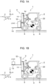
- FIG. 1 is a side view illustrating a forklift, which is a vehicle including a vehicle control device according to a first embodiment of the present invention.
- a forklift 1 according to the present embodiment is a counterbalance forklift.
- the forklift 1 includes a travelling device 2, and a loading device 3 disposed on the front side of the travelling device 2 and configured to lift a load up and down.
- the travelling device 2 includes a vehicle body 4, front wheels 5, which are a pair of drive wheels disposed in a front portion of the vehicle body 4, rear wheels 6, which are a pair of steering wheels disposed in a rear portion of the vehicle body 4, and a drive motor (illustration omitted) configured to rotate the front wheels 5.
- the loading device 3 is connected to a front end portion of the vehicle body 4.
- the loading device 3 includes a mast 11 provided in a standing manner at the front end portion of the vehicle body 4, a pair of forks 13, which is attached to the mast 11 via a lift bracket 12 and on which a load is to be loaded, a lift cylinder 14 configured to move the forks 13 up and down, and a tilt cylinder 15 configured to tilt the mast 11.
- the forklift 1 is capable of lifting loads having different weights up to various lifting heights.
- the forklift 1 is capable of lifting loads having different weights up at longitudinally different positions on the forks 13.
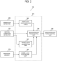
- FIG. 2 is a block diagram of a configuration of a vehicle control device according to the embodiment of the present invention.
- a vehicle control device 10 is mounted in the forklift 1.
- the vehicle control device 10 includes an operation detector 20, a motion condition detector 22, a pressure sensor 23, a computer 24 and a braking/driving force generator 26.
- the center-of-gravity inertia value calculation unit 33 receives a detection value outputted from an encoder provided on the lift cylinder 14, and calculates a height of the forks 13 relative to a reference position (for example, a lowermost portion) from a rotational angle of a lifting hydraulic motor, the rotational angle being indicated by the detection value, and acquires the height as a lift height.
- the wheel load variation calculation unit 44 calculates a wheel load variation of each wheel.
- the threshold value storage unit 46 acquires the wheel loads of the wheels in a state in which the forklift 1 is at a stop, that is, the forklift 1 is not travelling, and the differences between the wheel loads of the left and right wheels.
- the threshold value storage unit 46 sets a first threshold value and a second threshold value for the wheel load of each wheel, a third threshold value for the difference between the wheel loads of the front left and right wheels, and a fourth threshold value for the difference between the wheel loads of the rear left and right wheels according to the acquired wheel loads of the wheels in a state in which the forklift 1 is at a stop and the acquired differences between the wheel loads of the left and right wheels, and stores the threshold values.
- the third and fourth threshold values correspond to a difference threshold.
- each first threshold value is a start determination threshold value for determining a start of overturning prevention control for the relevant wheel
- each second threshold value is an end determination threshold value for determining an end of overturning prevention control for the relevant wheel.
- Each second threshold value is set to a value that is larger than the relevant first threshold value.
- FIGS. 4A, 4B and 4C each illustrate an example of measurement of loads in a three-wheel forklift.
- FIG. 4C indicates a relationship between the loading position on the forks (see FIGS. 5A and 5B ) and a wheel load of the front left wheel (FL wheel).
- FIG. 4C illustrates an example in which the loading load is the loading load "c" in FIG. 4A and the lift height is the lift height "C" as illustrated in FIG. 4B .
- the threshold value storage unit 46 sets the threshold values according to the wheel loads detected in a state where travelling of the forklift is stopped. For example, the threshold value storage unit 46 sets, for each wheel, 30% of a wheel load detection value of the wheel as the first threshold value for the wheel, 40% of the wheel load detection value of the wheel as the second threshold value for the wheel, and sets the third threshold value and the fourth threshold value to 30% of an average of the wheel loads of the front left and right wheels and the wheel loads of the rear left and right wheels.
- the first threshold value comparing unit 48 compares the wheel load detection value and the first threshold value for each wheel, and determines whether or not at least one wheel load detection value is smaller than the relevant first threshold value. If at least one wheel load detection value is smaller than the relevant first threshold value, a load difference determining unit 50 determines whether or not a difference between the loads of left and right wheels is smaller than the relevant threshold value, and if the difference between the loads of the left and right wheels is smaller than the relevant threshold value, the control selecting unit 54 starts longitudinal overturning prevention control.
- the control selecting unit 54 starts longitudinal overturning prevention control according to a result of comparison of the difference between the wheel loads of the front left and right wheels with the third threshold value or a result of comparison of the difference between the wheel loads of the rear left and right wheels with the fourth threshold value.
- the control selecting unit 54 starts longitudinal overturning prevention control that controls braking forces or driving forces of the drive wheels of the vehicle.
- the second threshold value comparing unit 52 compares the wheel load detection value and the second threshold value for each wheel and determines whether or not all of the wheel load detection values are larger than the respective second threshold values. If all of the wheel load detection values are larger than the respective second threshold values, the overturning prevention control is terminated.
- the control unit 56 calculates control amounts for controlling braking forces or driving forces of the drive wheels, using the inertia value including the principal axes of inertia about the center of gravity of the forklift 1 with the load included, the acquired wheel loads of the wheels, and the detection values of the motion conditions.
- control unit 56 includes a control amount arithmetic operation unit 80 and a braking/driving force calculation unit 82.
- the control amount arithmetic operation unit 80 calculates a pitch moment control amount PM, using the inertia value including the principal axes of inertia about the center of gravity of the forklift 1 with the load included, the acquired wheel loads of the wheels, and the detection values of the motion conditions.
- the pitch moment Mv is represented as a moment about CG all by expression (8).
- M ⁇ ⁇ M all ⁇ G xCG ⁇ h CG ⁇ ⁇ FL z + ⁇ FR z ⁇ l f + ⁇ RL z + ⁇ RR z ⁇ l r + PM
- Expression (8) is represented using a moment according to a longitudinal inertia force, a moment according to a wheel load variation, and a control moment PM for longitudinal overturning prevention.
- an IMU intial measurement unit
- G xCG a value converted into an acceleration at the position of the center of gravity based on the later-described expression is used.
- PM that makes a pitch angular acceleration Q ⁇ zero is obtained by the following expression, by transformation of expression (9) with J yy . Q on the left side of expression (9) as zero.
- PM J xy ⁇ P ⁇ + J yz ⁇ R ⁇ ⁇ ⁇ J xx ⁇ R + J xz ⁇ P ⁇ P + ⁇ J xy ⁇ R + J yz ⁇ P ⁇ Q + ⁇ J xz ⁇ R + J zz ⁇ P ⁇ R + M all ⁇ G xCG ⁇ h CG + ⁇ FL z + ⁇ FR z ⁇ l f ⁇ ⁇ RL z + ⁇ RR z ⁇ l r
- control amount arithmetic operation unit 80 calculates the pitch moment control amount PM according to expressions (10) and (11), using the inertia value including the principal axes of inertia about the center of gravity of the forklift 1 with the load included, the acquired wheel loads of the wheels and the detection values of the motion conditions.
- the braking/driving force calculation unit 82 calculates control amounts F FL , F FR for braking forces or driving forces of the front left and right wheels in such a manner as to obtain the pitch moment control amount PM.
- "Dir" in FIG. 10 is a flag indicating forward travelling or rearward travelling, in which '+1' denotes forward travelling and '-1' denotes rearward travelling.
- the pitch control amount PM is converted into a tire braking/driving force by being divided by h CG , and the tire braking/driving force is distributed into tire braking/driving forces of the left and right wheels by being further divided by 2.
- control amount switching unit 58 outputs control amounts F (i) for braking forces or driving forces, which have been obtained by the control unit 56.
- the braking/driving force instruction value setting unit 62 sets the control amounts F (i) for braking forces or driving forces, which have been output by the low-pass filter 60, as instruction values F x(i) for braking forces or driving forces of the left and right wheels.
- the braking/driving force generator 26 generates the instruction values F x(i) for braking forces or driving forces of the left and right drive wheels.
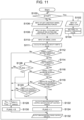
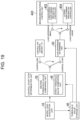
- the overturning prevention control processing routine illustrated in FIG. 11 is executed.
- the description will be given taking a case where the forklift 1 is a front-wheel-drive forklift, as an example.
- step S100 whether or not the forklift 1 is at a stop is determined, and if it is determined that the forklift 1 is at a stop, the routine proceeds to step S102, and if it is determined that the forklift 1 is not at a stop, the routine proceeds to step S106.
- step S102 the wheel load acquisition unit 32 detects wheel loads of the wheels (i.e., the input of the wheel loads F z(i) ).
- the control parameter changing unit 42 and the threshold value storage unit 46 acquire wheel loads of the wheels in a state in which the forklift 1 is at a stop and differences between the wheel loads of the left and right wheels.
- step S106 the operational braking/driving force acquisition unit 30 acquires control amounts F DRV(i) for braking forces and driving forces of the drive wheels, based on the driver's operation detected by the operation detector 20 (the input of left and right wheel braking/driving forces F DRV(i) based on instruction by driver's operation).
- step S108 the motion condition detector 22 detects a roll angular velocity P, a pitch angular velocity Q, a yaw angular velocity R and a longitudinal acceleration G x as motion conditions of the forklift 1, using the IMU (an input of the roll, pitch and yaw angular velocities P, Q, R and the longitudinal acceleration G x ).
- step S110 the wheel load acquisition unit 32 detects the wheel loads of the wheels of the forklift 1 (i.e., the input of the wheel loads F z(i) ).
- step S111 the center-of-gravity inertia value calculation unit 33 acquires a loading state of a load loaded on the forklift 1, and based on the acquired loading state, calculates a position of a center of gravity of the forklift 1 with the load included, and calculates an inertia value including principal axes of inertia about the center of gravity of the forklift 1 with the load included, according to expression (4) above.
- the second threshold value comparing unit 52 compares the wheel load detection value and the relevant second threshold value for each wheel, and determines whether if all of the wheel load detection values are larger than the respective second threshold values, that is, whether or not at least one wheel load detection value is equal to or smaller than the relevant second threshold value. If at least one wheel load detection value is equal to or smaller than the relevant second threshold value, the routine proceeds to step S114. On the other hand, if all of the wheel load detection values are larger than the respective second threshold values, a determination is made to terminate the overturning prevention control, and the routine proceeds to step S128.
- step S114 the first threshold value comparing unit 48 compares the wheel load detection value and the first threshold value for each wheel, and determines whether or not at least one wheel load detection value is smaller than the relevant first threshold value. If at least one wheel load detection value is smaller than the relevant first threshold value, a determination is made to start overturning prevention control, and the routine proceeds to step S116. On the other hand, if all of the wheel load detection values are equal to or larger than the respective first threshold values, the routine proceeds to step S126.
- step S1208 the control amounts F DRV(i) for the braking forces or the driving forces, which have been acquired by the operational braking/driving force acquisition unit 30, are set as the control amounts F FL , F FR for braking forces or driving forces of the front left and right wheels.
- control amount arithmetic operation unit 280 calculates the yaw moment control amount YM according to expressions (27) and (28), using the inertia value including the principal axes of inertia about the center of gravity of the forklift 1 with the load included, the acquired wheel loads of the wheels, the detection values of the motion conditions, and the detection values of the tire lateral forces.
- the braking/driving force calculation unit 282 calculates control amounts F FL , F FR for braking forces or driving forces of the front left and right wheels in such a manner as to obtain the yaw moment control amount YM.
- "Dir" in FIG. 14A and 14B is a flag indicating forward or backward travelling, in which '+1' is forward travelling and '-1' is backward travelling. When it is turning right, as illustrated in FIG.
- the yaw moment control amount YM is converted into a tire braking/driving force by being divided by Tr, which is a distance between the left and right wheels, and the tire braking/driving force is multiplied by '0' for the right wheel and '-2' for the left wheel to obtain tire braking/driving forces of the left and right wheels.
- Tr a distance between the left and right wheels
- the tire braking/driving force is multiplied by '0' for the right wheel and '-2' for the left wheel to obtain tire braking/driving forces of the left and right wheels.
- the yaw moment control amount YM is converted into a tire braking/driving force by being divided by Tr, and the tire braking/driving force is multiplied by '2' for the right wheel and '0' for the left wheel to obtain tire braking/driving forces of the left and right wheels.
- control amount switching unit 258 outputs the control amounts F FL , F FR for braking forces or driving forces, which have been obtained by the control unit 256.
- the low-pass filter 60 performs low-pass filtering. More specifically, the low-pass filter 60 performs low-pass filtering for values resulting from addition of the control amounts F FL , F FR for braking forces or driving forces, which have been output by the control amount switching unit 258, to control amounts F DRV(i) for braking forces or driving forces, which have been acquired by the operational braking/driving force acquisition unit 30.
- the braking/driving force instruction value setting unit 262 sets the values output by the low-pass filter 60, as instruction values F x(i) for braking forces or driving forces of the left and right wheels.
- a braking/driving force generator 26 generates the instruction values F x(i) for braking forces or driving forces of the left and right drive wheels.
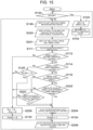
- the overturning prevention control processing routine illustrated in FIG. 15 is executed. Note that processing that is similar to that of the first embodiment is provided with the same sign as that of the first embodiment, and the detailed description thereof is omitted.
- step S100 whether or not the forklift 1 is at a stop is determined, and if it is determined that the forklift 1 is at a stop, the routine proceeds to step S102, and if it is determined that the forklift 1 is not at a stop, the routine proceeds to step S106.
- a wheel load acquisition unit 32 detects wheel loads of the wheels (i.e., the input of the wheel loads F z(i) ).
- the control parameter changing unit 42 and the threshold value storage unit 46 acquire wheel loads of the wheels in a state in which the forklift 1 is at a stop and differences between the wheel loads of the left and right wheels.
- step S104 the threshold value storage unit 46 sets a first threshold value and a second threshold value for the wheel load of each wheel, a third threshold value for the difference between the wheel loads of the front left and right wheels and a fourth threshold value for the difference between the wheel loads of the rear left and right wheels according to the wheel loads of the wheels in a state in which the forklift 1 is at a stop and the differences between the wheel loads of the left and right wheels, which have been acquired in step S102 above, and the routine returns to step S100.
- the control parameter changing unit 42 and the threshold value storage unit 46 corresponds to a threshold value changer that acquire wheel loads of the wheels in a state in which the vehicle is at a stop and a difference between the wheel loads of left and right wheels, and change threshold values for the wheel loads of the wheels and a threshold value for the difference between the wheel loads of the left and right wheels according to the wheel loads of the wheel.
- step S106 the operational braking/driving force acquisition unit 30 acquires control amounts F DRV(i) for braking forces and driving forces of the drive wheels, based on the driver's operation detected by the operation detector 20 (the input of left and right wheel braking/driving forces F DRV(i) based on instruction by driver's operation).
- a motion condition detector 22 detects a roll angular velocity P, a pitch angular velocity Q, a yaw angular velocity R and a lateral acceleration G y as motion conditions of the forklift 1, using an IMU (an input of the roll, pitch and yaw angular velocities P, Q, R and the lateral acceleration G y )
- step S201 the wheel load acquisition unit 32 detects wheel loads of the wheels of the forklift 1. Also, the tire lateral force detection unit 232 detects tire lateral forces of the wheels of the forklift 1 (i.e., the input of the lateral forces and the wheel loads Fz(i)).
- a center-of-gravity inertia value calculation unit 33 acquires a loading state of a load loaded on the forklift 1, and based on the acquired loading state, calculates a position of a center of gravity of the forklift 1 with the load included, and calculates an inertia value including principal axes of inertia about the center of gravity of the forklift 1 with the load included, according to expression (4) above.
- step S112 the second threshold value comparing unit 52 compares the wheel load detection value and the relevant second threshold value for each wheel, and determines whether if all of the wheel load detection values are larger than the respective second threshold values, that is, whether or not at least one wheel load detection value is equal to or smaller than the relevant second threshold value in step S112. If at least one wheel load detection value is equal to or smaller than the relevant second threshold value, the routine proceeds to step S114. On the other hand, if all of the wheel load detection values are larger than the respective second threshold values, a determination is made to terminate the overturning prevention control, and the routine proceeds to step S206.
- step S114 the first threshold value comparing unit 48 compares the wheel load detection value and the first threshold value for each wheel, and determines whether or not at least one wheel load detection value is smaller than the relevant first threshold value. If at least one wheel load detection value is smaller than the relevant first threshold value, a determination is made to start overturning prevention control, and the routine proceeds to step S116. On the other hand, if all of the wheel load detection values are equal to or larger than the respective first threshold values, the routine proceeds to step S126.
- step S116 whether or not the wheel load detection value that is smaller than the relevant first threshold value is that of a front wheel is determined (a decrease in the wheel load in the front wheel). If the wheel load detection value that is smaller than the relevant first threshold value is determined to be that of a front wheel, the routine proceeds to step S202. On the other hand, if the wheel load detection value that is smaller than the relevant first threshold value is determined to be that of a rear wheel, the routine proceeds to step S203.
- step S202 whether or not an absolute value of the difference between the wheel loads of the front left and right wheels
- step S203 whether or not an absolute value of the difference between the wheel loads of the rear left and right wheels
- step S204 the control amount arithmetic operation unit 280 calculates a yaw moment control amount YM according to expressions (27) and (28), using the inertia value including the principal axes of inertia about the center of gravity of the forklift 1 with the load included, the acquired wheel loads of the wheels, detection values of the motion conditions and detection values of the tire lateral forces.
- the braking/driving force calculation unit 282 calculates the control amounts F FL , F FR for braking forces or driving forces of the front left and right wheels in such a manner as to obtain the yaw moment control amount YM.
- step S124 "1" is set for a flag FLAG indicating a start of overturning prevention control.
- step S206 the control amounts F FL , F FR for braking forces or driving forces of the front left and right wheels are set to 0.
- step S208 the braking/driving force instruction value setting unit 62 sets the control amounts F FL , F FR for the braking forces or the driving forces, which have been obtained in step S122 or S128 above, as instruction values F x(i) for braking forces or driving forces of the left and right wheels (an output of the control amounts F FL , F FR ).
- the braking/driving force generator 26 generates the instruction values F x(i) for braking forces or driving forces of the left and right drive wheels. Then, the routine returns to step S106.
- the overturning prevention control is properly performed according to a loading state of a load by performing lateral overturning prevention control of a forklift using the acquired wheel loads of wheels, the inertia value including principal axes of inertia about the center of gravity of the forklift with the load included, and the detection values of motion conditions.
- the controller is configured to perform overturning prevention control that suppresses an increase in difference between the wheel loads of left and right wheels of the vehicle, using the acquired wheel loads of the wheels, the inertia value, and detection values of the motion conditions.
- the tire lateral force moment calculation unit 332 calculates a physical value relating to a moment caused by tire lateral forces, based on a derivative value R of a yaw angular velocity R and differences between a position of a center of gravity of the entire forklift 1 and positions of centers of gravity of components.
Landscapes
- Engineering & Computer Science (AREA)
- Transportation (AREA)
- Mechanical Engineering (AREA)
- Automation & Control Theory (AREA)
- Structural Engineering (AREA)
- Mathematical Physics (AREA)
- Physics & Mathematics (AREA)
- Geology (AREA)
- Life Sciences & Earth Sciences (AREA)
- Chemical & Material Sciences (AREA)
- Combustion & Propulsion (AREA)
- Civil Engineering (AREA)
- Forklifts And Lifting Vehicles (AREA)
Claims (9)
- Fahrzeugsteuervorrichtung, umfassend:ein Bewegungszustandsdetektor (22), der konfiguriert ist, um die Bewegungszustände eines Fahrzeugs (1) zu erfassen, auf das eine Last geladen werden soll, die Bewegungszustände, einschließlich einer Drehbewegung und einer Längsbeschleunigung des Fahrzeugs (1);eine Ladezustandserfassungseinheit, die konfiguriert ist, um den Ladezustand der auf das Fahrzeug (1) geladenen Last zu erfassen;ein Trägheitswertrechner, der konfiguriert ist, um einen Trägheitswert zu berechnen einschließlich der Hauptträgheitsachsen um den Schwerpunkt des Fahrzeugs (1) mit der Ladung, basierend auf dem erfassten Beladungszustand;gekennzeichnet durch:
eine Radlastmesseinheit (32), die konfiguriert ist, um die Radlasten der Räder des Fahrzeugs (1) zu messen;eine Steuereinheit, die konfiguriert ist, um eine Längs-Überrollschutzsteuerung durchzuführen, um eine Zunahme der Differenz zwischen den Radlasten der Vorder- und Hinterräder des Fahrzeugs (1) zu unterdrücken, indem Steuergrößen zur Steuerung von Bremskräften oder Antriebskräften der linken und rechten Antriebsräder des Fahrzeugs (1) unter Verwendung der erfassten Radlasten der Räder, des Trägheitswerts und der Erfassungswerte der Bewegungsbedingungen berechnet werden; undeinen Brems-/Antriebskraftgenerator (26), der konfiguriert ist, um Anweisungswerte (Fx(i)) für die Bremskräfte oder Antriebskräfte der linken und rechten Antriebsräder des Fahrzeugs (1) zu erzeugen. - Fahrzeugsteuervorrichtung, umfassend:ein Bewegungszustandsdetektor (22), der konfiguriert ist, um die Bewegungszustände eines Fahrzeugs (1) zu erfassen, auf das eine Last darauf geladen werden soll, die Bewegungszustände, einschließlich einer Drehbewegung und einer Querbeschleunigung des Fahrzeugs (1);eine Ladezustandserfassungseinheit, die konfiguriert ist, um den Ladezustand der auf das Fahrzeug (1) geladenen Last zu erfassen;ein Trägheitswertrechner, der konfiguriert ist, um einen Trägheitswert zu berechnen einschließlich der Hauptträgheitsachsen um den Schwerpunkt des Fahrzeugs (1) mit der Ladung, basierend auf dem erfassten Beladungszustand;gekennzeichnet durch:
eine Radlastmesseinheit (32), die konfiguriert ist, um die Radlasten der Räder des Fahrzeugs (1) zu messen;eine Steuereinheit, die konfiguriert ist, um eine Quer-Überrollschutzsteuerung durchzuführen, um eine Zunahme der Differenz zwischen den Radlasten der linken und rechten Räder des Fahrzeugs (1) zu unterdrücken, indem Steuergrößen zur Steuerung von Bremskräften oder Antriebskräften der linken und rechten Antriebsräder des Fahrzeugs (1) unter Verwendung der erfassten Radlasten der Räder, des Trägheitswerts und der Erfassungswerte der Bewegungsbedingungen berechnet werden; undeinen Brems-/Antriebskraftgenerator (26), der konfiguriert ist, um Anweisungswerte (Fx(i)) für die Bremskräfte oder Antriebskräfte der linken und rechten Antriebsräder des Fahrzeugs (1) zu erzeugen. - Fahrzeugsteuervorrichtung nach Anspruch 1 oder 2, weiter umfassend ein Schwellwertwandler, der konfiguriert ist, um die Radlasten der Räder in einem Zustand zu erfassen, in dem das Fahrzeug (1) steht, und einen Unterschied zwischen den Radlasten der linken und rechten Räder und Änderung der Schwellenwerte für die Radlasten der Räder und einen Differenzschwellenwert für die Differenz zwischen den Radlasten der linken und rechten Räder entsprechend den Radlasten der Räder in einem Zustand, in dem das Fahrzeug (1) steht, und die Differenz zwischen den Radlasten der linken und rechten Räder,
wobei die Steuereinheit die Überrollschutzsteuerung basierend auf einem Ergebnis eines Vergleichs der erfassten Radlasten der Räder mit den Schwellenwerten, einem Ergebnis eines Vergleichs der Differenz zwischen den Radlasten der linken und rechten Räder mit dem Differenzschwellenwert, dem Trägheitswert und den Erfassungswerten der Bewegungsbedingungen durchführt. - Fahrzeugsteuervorrichtung nach Anspruch 1, wobei die Steuereinheit die Überrollschutzsteuerung gemäß einem Ergebnis eines Vergleichs der Differenz zwischen den Radlasten der Vorder- und Hinterräder mit einem Differenzschwellenwert durchführt.
- Fahrzeugsteuervorrichtung nach Anspruch 2, wobei die Steuereinheit die Überrollschutzsteuerung gemäß einem Ergebnis eines Vergleichs der Differenz zwischen den Radlasten der linken und rechten Räder mit einem Differenzschwellenwert durchführt.
- Fahrzeugsteuervorrichtung nach Anspruch 1, wobei:Schwellenwerte für die Radlast jedes Rads einen Startbestimmungsschwellenwert zur Bestimmung des Beginns der Überrollschutzsteuerung für das Rad und einen Endbestimmungsschwellenwert zur Bestimmung des Endes des Überrollschutzsteuerungswerts für das Rad einschließen,die Steuereinheit die Überrollschutzsteuerung durchführt, wenn die Radlast von mindestens einem Rad kleiner als der Startbestimmungsschwellenwert für die Radlast des Rads ist und ein absoluter Wert der Differenz zwischen den Radlasten der Vorder- und Hinterräder kleiner als ein Differenzschwellenwert für die Differenz zwischen den Radlasten der Vorder- und Hinterräder ist, unddie Steuereinheit die Überrollschutzsteuerung stoppt, wenn alle Radlasten der Räder größer sind als die jeweiligen Endbestimmungsschwellenwerte für die Radlasten der Räder.
- Fahrzeugsteuervorrichtung nach Anspruch 2, wobeiSchwellenwerte für die Radlast jedes Rads einen Startbestimmungsschwellenwert zur Bestimmung des Beginns der Überrollschutzsteuerung für das Rad und einen Endbestimmungsschwellenwert zur Bestimmung des Endes der Überrollschutzsteuerung für das Rad einschließt,die Steuereinheit die Überrollschutzsteuerung durchführt, wenn die Radlast von mindestens einem Rad kleiner als der Startbestimmungsschwellenwert für die Radlast des Rads ist und ein absoluter Wert der Differenz zwischen den Radlasten der linken und rechten Räder kleiner als ein Schwellenwert für die Differenz zwischen den Radlasten der linken und rechten Räder ist, unddie Steuereinheit die Überrollschutzsteuerung stoppt, wenn alle Radlasten der Räder größer sind als die jeweiligen Endbestimmungsschwellenwerte für die Radlasten der Räder.
- Fahrzeugsteuerungsprogramm, das einen Computer (24) wie folgt funktionieren lässt:eine Radlastmesseinheit (32), die konfiguriert ist, um die Radlasten der Räder eines Fahrzeugs (1) zu messen;eine Ladezustandserfassungseinheit, die konfiguriert ist, um den Ladezustand einer auf dem Fahrzeug (1) geladenen Ladung erfasst;ein Trägheitswertrechner, der konfiguriert ist, um einen Trägheitswert zu berechnen einschließlich der Hauptträgheitsachsen um den Schwerpunkt des Fahrzeugs (1) mit der Ladung, basierend auf dem erfassten Beladungszustand; undeine Steuereinheit, die konfiguriert ist, um eine Längs-Überrollschutzsteuerung durchzuführen, um eine Zunahme der Differenz zwischen den Radlasten der Vorder- und Hinterräder von dem Fahrzeug (1) durchzuführen, indem Steuergrößen für die Steuerung der Bremskräfte oder Antriebskräfte der linken und rechten Antriebsräder des Fahrzeugs unter Verwendung der erfassten Radlasten der Räder, des Trägheitswerts und der Erfassungswerte der Bewegungszustände des Fahrzeugs (1) berechnet werden einschließlich einer Drehbewegung und einer Längsbeschleunigung des Fahrzeugs (1).
- Fahrzeugsteuerungsprogramm, das einen Computer (24) wie folgt funktionieren lässt:eine Radlastmesseinheit (32), die konfiguriert ist, um die Radlasten der Räder eines Fahrzeugs (1) zu messen;eine Ladezustandserfassungseinheit, die konfiguriert ist, um den Ladezustand einer auf dem Fahrzeug (1) geladenen Ladung erfasst;ein Trägheitswertrechner, der konfiguriert ist, um einen Trägheitswert zu berechnen einschließlich der Hauptträgheitsachsen um den Schwerpunkt des Fahrzeugs (1) mit der Ladung, basierend auf dem erfassten Beladungszustand; undeine Steuereinheit, die konfiguriert ist, um eine Längs-Überrollschutzsteuerung durchzuführen, um eine Zunahme der Differenz zwischen den Radlasten der Vorder- und Hinterräder von dem Fahrzeug (1) durchzuführen, indem Steuergrößen für die Steuerung der Bremskräfte oder Antriebskräfte der linken und rechten Antriebsräder des Fahrzeugs unter Verwendung der erfassten Radlasten der Räder, des Trägheitswerts und der Erfassungswerte der Bewegungszustände des Fahrzeugs (1) berechnet werden einschließlich einer Drehbewegung und einer Längsbeschleunigung des Fahrzeugs (1).
Applications Claiming Priority (2)
| Application Number | Priority Date | Filing Date | Title |
|---|---|---|---|
| JP2021040319 | 2021-03-12 | ||
| JP2022028502A JP7728716B2 (ja) | 2021-03-12 | 2022-02-25 | 車両制御装置及び車両制御プログラム |
Publications (2)
| Publication Number | Publication Date |
|---|---|
| EP4071010A1 EP4071010A1 (de) | 2022-10-12 |
| EP4071010B1 true EP4071010B1 (de) | 2025-07-09 |
Family
ID=80735513
Family Applications (1)
| Application Number | Title | Priority Date | Filing Date |
|---|---|---|---|
| EP22161333.4A Active EP4071010B1 (de) | 2021-03-12 | 2022-03-10 | Fahrzeugsteuerungsvorrichtung und fahrzeugsteuerungsprogramm |
Country Status (2)
| Country | Link |
|---|---|
| US (1) | US12145602B2 (de) |
| EP (1) | EP4071010B1 (de) |
Families Citing this family (4)
| Publication number | Priority date | Publication date | Assignee | Title |
|---|---|---|---|---|
| JP7480590B2 (ja) * | 2020-05-27 | 2024-05-10 | 株式会社デンソー | 推定装置 |
| US12060068B2 (en) * | 2022-04-28 | 2024-08-13 | Toyota Research Institute, Inc. | Low speed cornering stiffness derate using a dynamic vehicle model |
| US11752882B1 (en) * | 2022-11-03 | 2023-09-12 | Ayro, Inc. | Systems and methods for controlling vehicle acceleration to regulate environmental impact |
| CN119191175B (zh) * | 2024-10-18 | 2026-03-10 | 三一海洋重工有限公司 | 堆高机作业姿态的控制方法、装置、控制器及堆高机 |
Family Cites Families (9)
| Publication number | Priority date | Publication date | Assignee | Title |
|---|---|---|---|---|
| JPS6137568A (ja) * | 1984-07-31 | 1986-02-22 | Nissan Motor Co Ltd | ブレ−キ液圧制御装置 |
| US7216024B1 (en) * | 1999-07-27 | 2007-05-08 | Linde Aktiengesellschaft | Industrial truck with a stabilizing device |
| JP2005200212A (ja) * | 2003-11-20 | 2005-07-28 | Mitsubishi Heavy Ind Ltd | フォークリフトの転倒防止装置 |
| JP4747722B2 (ja) | 2005-08-04 | 2011-08-17 | いすゞ自動車株式会社 | 車両の横転防止装置 |
| US8140228B2 (en) * | 2009-03-27 | 2012-03-20 | The Raymond Corporation | System and method for dynamically maintaining the stability of a material handling vehicle having a vertical lift |
| JP6282108B2 (ja) | 2013-12-25 | 2018-02-21 | 住友重機械工業株式会社 | 電動フォークリフト用モータ駆動装置およびそれを用いたフォークリフト |
| GB2539240A (en) * | 2015-06-11 | 2016-12-14 | Bentley Motors Ltd | Method of estimating load on a vehicle |
| US11807508B2 (en) | 2018-08-31 | 2023-11-07 | Hyster-Yale Group, Inc. | Dynamic stability determination system for lift trucks |
| JP7135821B2 (ja) | 2018-12-14 | 2022-09-13 | 株式会社豊田自動織機 | 荷役車両の重心推定装置 |
-
2022
- 2022-03-10 EP EP22161333.4A patent/EP4071010B1/de active Active
- 2022-03-10 US US17/691,411 patent/US12145602B2/en active Active
Also Published As
| Publication number | Publication date |
|---|---|
| EP4071010A1 (de) | 2022-10-12 |
| US12145602B2 (en) | 2024-11-19 |
| US20220289208A1 (en) | 2022-09-15 |
Similar Documents
| Publication | Publication Date | Title |
|---|---|---|
| EP4071010B1 (de) | Fahrzeugsteuerungsvorrichtung und fahrzeugsteuerungsprogramm | |
| US6593849B2 (en) | Wheel lift identification for an automotive vehicle | |
| US8219282B2 (en) | System for dynamically determining vehicle rear/trunk loading for use in a vehicle control system | |
| EP3421341B1 (de) | Vorrichtung zur steuerung einer neigehaltung für neigefahrzeug mit daran montierten linken und rechten geneigten rädern und neigefahrzeug mit daran montierten linken und rechten geneigten rädern | |
| JP7699520B2 (ja) | 輪荷重推定装置及びプログラム | |
| US7451032B2 (en) | System and method for determining desired yaw rate and lateral velocity for use in a vehicle dynamic control system | |
| US9169110B2 (en) | Method for determining the probability of a handling truck's tipping over | |
| US20040019418A1 (en) | Wheel lifted and grounded identification for an automotive vehicle | |
| US20040254707A1 (en) | System for determining vehicular relative roll angle during a potential rollover event | |
| US20040010383A1 (en) | Passive wheel lift identification for an automotive vehicle using operating input torque to wheel | |
| US20040030473A1 (en) | System for dynamically determining the wheel grounding and wheel lifting conditions and their applications in roll stability control | |
| US20080117035A1 (en) | Wheel lifted and grounded identification for an automotive vehicle | |
| US20040041358A1 (en) | Roll over stability control for an automotive vehicle having an active suspension | |
| US20040064246A1 (en) | Wheel lift identification for an automotive vehicle using passive and active detection | |
| JP7728716B2 (ja) | 車両制御装置及び車両制御プログラム | |
| US20250164335A1 (en) | Wheel load estimation device, vehicle, program, and wheel load estimation method | |
| JP2022070707A (ja) | 車両制御装置及び車両制御プログラム | |
| JP2024090428A (ja) | 車両制御装置、車両、プログラム及び車両制御方法 | |
| CN119078797A (zh) | 车辆控制方法、车辆控制装置、车辆及存储介质 | |
| JP2005178532A (ja) | 車体姿勢制御装置 |
Legal Events
| Date | Code | Title | Description |
|---|---|---|---|
| PUAI | Public reference made under article 153(3) epc to a published international application that has entered the european phase |
Free format text: ORIGINAL CODE: 0009012 |
|
| STAA | Information on the status of an ep patent application or granted ep patent |
Free format text: STATUS: REQUEST FOR EXAMINATION WAS MADE |
|
| 17P | Request for examination filed |
Effective date: 20220310 |
|
| AK | Designated contracting states |
Kind code of ref document: A1 Designated state(s): AL AT BE BG CH CY CZ DE DK EE ES FI FR GB GR HR HU IE IS IT LI LT LU LV MC MK MT NL NO PL PT RO RS SE SI SK SM TR |
|
| P01 | Opt-out of the competence of the unified patent court (upc) registered |
Effective date: 20230519 |
|
| GRAP | Despatch of communication of intention to grant a patent |
Free format text: ORIGINAL CODE: EPIDOSNIGR1 |
|
| STAA | Information on the status of an ep patent application or granted ep patent |
Free format text: STATUS: GRANT OF PATENT IS INTENDED |
|
| INTG | Intention to grant announced |
Effective date: 20250307 |
|
| GRAS | Grant fee paid |
Free format text: ORIGINAL CODE: EPIDOSNIGR3 |
|
| GRAA | (expected) grant |
Free format text: ORIGINAL CODE: 0009210 |
|
| STAA | Information on the status of an ep patent application or granted ep patent |
Free format text: STATUS: THE PATENT HAS BEEN GRANTED |
|
| AK | Designated contracting states |
Kind code of ref document: B1 Designated state(s): AL AT BE BG CH CY CZ DE DK EE ES FI FR GB GR HR HU IE IS IT LI LT LU LV MC MK MT NL NO PL PT RO RS SE SI SK SM TR |
|
| REG | Reference to a national code |
Ref country code: GB Ref legal event code: FG4D |
|
| REG | Reference to a national code |
Ref country code: CH Ref legal event code: EP |
|
| REG | Reference to a national code |
Ref country code: IE Ref legal event code: FG4D |
|
| REG | Reference to a national code |
Ref country code: DE Ref legal event code: R096 Ref document number: 602022017162 Country of ref document: DE |
|
| REG | Reference to a national code |
Ref country code: SE Ref legal event code: TRGR |
|
| REG | Reference to a national code |
Ref country code: NL Ref legal event code: FP |
|
| PG25 | Lapsed in a contracting state [announced via postgrant information from national office to epo] |
Ref country code: PT Free format text: LAPSE BECAUSE OF FAILURE TO SUBMIT A TRANSLATION OF THE DESCRIPTION OR TO PAY THE FEE WITHIN THE PRESCRIBED TIME-LIMIT Effective date: 20251110 |
|
| REG | Reference to a national code |
Ref country code: AT Ref legal event code: MK05 Ref document number: 1811605 Country of ref document: AT Kind code of ref document: T Effective date: 20250709 |
|
| PG25 | Lapsed in a contracting state [announced via postgrant information from national office to epo] |
Ref country code: IS Free format text: LAPSE BECAUSE OF FAILURE TO SUBMIT A TRANSLATION OF THE DESCRIPTION OR TO PAY THE FEE WITHIN THE PRESCRIBED TIME-LIMIT Effective date: 20251109 |
|
| PG25 | Lapsed in a contracting state [announced via postgrant information from national office to epo] |
Ref country code: NO Free format text: LAPSE BECAUSE OF FAILURE TO SUBMIT A TRANSLATION OF THE DESCRIPTION OR TO PAY THE FEE WITHIN THE PRESCRIBED TIME-LIMIT Effective date: 20251009 |
|
| REG | Reference to a national code |
Ref country code: LT Ref legal event code: MG9D |
|
| PG25 | Lapsed in a contracting state [announced via postgrant information from national office to epo] |
Ref country code: AT Free format text: LAPSE BECAUSE OF FAILURE TO SUBMIT A TRANSLATION OF THE DESCRIPTION OR TO PAY THE FEE WITHIN THE PRESCRIBED TIME-LIMIT Effective date: 20250709 |
|
| PG25 | Lapsed in a contracting state [announced via postgrant information from national office to epo] |
Ref country code: FI Free format text: LAPSE BECAUSE OF FAILURE TO SUBMIT A TRANSLATION OF THE DESCRIPTION OR TO PAY THE FEE WITHIN THE PRESCRIBED TIME-LIMIT Effective date: 20250709 |
|
| PG25 | Lapsed in a contracting state [announced via postgrant information from national office to epo] |
Ref country code: HR Free format text: LAPSE BECAUSE OF FAILURE TO SUBMIT A TRANSLATION OF THE DESCRIPTION OR TO PAY THE FEE WITHIN THE PRESCRIBED TIME-LIMIT Effective date: 20250709 |
|
| PG25 | Lapsed in a contracting state [announced via postgrant information from national office to epo] |
Ref country code: GR Free format text: LAPSE BECAUSE OF FAILURE TO SUBMIT A TRANSLATION OF THE DESCRIPTION OR TO PAY THE FEE WITHIN THE PRESCRIBED TIME-LIMIT Effective date: 20251010 |
|
| PG25 | Lapsed in a contracting state [announced via postgrant information from national office to epo] |
Ref country code: LV Free format text: LAPSE BECAUSE OF FAILURE TO SUBMIT A TRANSLATION OF THE DESCRIPTION OR TO PAY THE FEE WITHIN THE PRESCRIBED TIME-LIMIT Effective date: 20250709 |
|
| PG25 | Lapsed in a contracting state [announced via postgrant information from national office to epo] |
Ref country code: PL Free format text: LAPSE BECAUSE OF FAILURE TO SUBMIT A TRANSLATION OF THE DESCRIPTION OR TO PAY THE FEE WITHIN THE PRESCRIBED TIME-LIMIT Effective date: 20250709 Ref country code: BG Free format text: LAPSE BECAUSE OF FAILURE TO SUBMIT A TRANSLATION OF THE DESCRIPTION OR TO PAY THE FEE WITHIN THE PRESCRIBED TIME-LIMIT Effective date: 20250709 |
|
| PG25 | Lapsed in a contracting state [announced via postgrant information from national office to epo] |
Ref country code: RS Free format text: LAPSE BECAUSE OF FAILURE TO SUBMIT A TRANSLATION OF THE DESCRIPTION OR TO PAY THE FEE WITHIN THE PRESCRIBED TIME-LIMIT Effective date: 20251009 |
|
| PG25 | Lapsed in a contracting state [announced via postgrant information from national office to epo] |
Ref country code: ES Free format text: LAPSE BECAUSE OF FAILURE TO SUBMIT A TRANSLATION OF THE DESCRIPTION OR TO PAY THE FEE WITHIN THE PRESCRIBED TIME-LIMIT Effective date: 20250709 |
|
| PGFP | Annual fee paid to national office [announced via postgrant information from national office to epo] |
Ref country code: NL Payment date: 20260213 Year of fee payment: 5 |
|
| PG25 | Lapsed in a contracting state [announced via postgrant information from national office to epo] |
Ref country code: SM Free format text: LAPSE BECAUSE OF FAILURE TO SUBMIT A TRANSLATION OF THE DESCRIPTION OR TO PAY THE FEE WITHIN THE PRESCRIBED TIME-LIMIT Effective date: 20250709 |
|
| PGFP | Annual fee paid to national office [announced via postgrant information from national office to epo] |
Ref country code: SE Payment date: 20260211 Year of fee payment: 5 |
|
| PGFP | Annual fee paid to national office [announced via postgrant information from national office to epo] |
Ref country code: GB Payment date: 20260202 Year of fee payment: 5 |
|
| PG25 | Lapsed in a contracting state [announced via postgrant information from national office to epo] |
Ref country code: DK Free format text: LAPSE BECAUSE OF FAILURE TO SUBMIT A TRANSLATION OF THE DESCRIPTION OR TO PAY THE FEE WITHIN THE PRESCRIBED TIME-LIMIT Effective date: 20250709 |
|
| PGFP | Annual fee paid to national office [announced via postgrant information from national office to epo] |
Ref country code: DE Payment date: 20260128 Year of fee payment: 5 |
|
| PGFP | Annual fee paid to national office [announced via postgrant information from national office to epo] |
Ref country code: BE Payment date: 20260217 Year of fee payment: 5 Ref country code: IT Payment date: 20260220 Year of fee payment: 5 |
|
| PGFP | Annual fee paid to national office [announced via postgrant information from national office to epo] |
Ref country code: FR Payment date: 20260209 Year of fee payment: 5 |
|
| PG25 | Lapsed in a contracting state [announced via postgrant information from national office to epo] |
Ref country code: CZ Free format text: LAPSE BECAUSE OF FAILURE TO SUBMIT A TRANSLATION OF THE DESCRIPTION OR TO PAY THE FEE WITHIN THE PRESCRIBED TIME-LIMIT Effective date: 20250709 |
|
| PG25 | Lapsed in a contracting state [announced via postgrant information from national office to epo] |
Ref country code: SK Free format text: LAPSE BECAUSE OF FAILURE TO SUBMIT A TRANSLATION OF THE DESCRIPTION OR TO PAY THE FEE WITHIN THE PRESCRIBED TIME-LIMIT Effective date: 20250709 Ref country code: EE Free format text: LAPSE BECAUSE OF FAILURE TO SUBMIT A TRANSLATION OF THE DESCRIPTION OR TO PAY THE FEE WITHIN THE PRESCRIBED TIME-LIMIT Effective date: 20250709 |