EP4071035A1 - Dispositif antivol pour motocycles - Google Patents
Dispositif antivol pour motocycles Download PDFInfo
- Publication number
- EP4071035A1 EP4071035A1 EP22000099.6A EP22000099A EP4071035A1 EP 4071035 A1 EP4071035 A1 EP 4071035A1 EP 22000099 A EP22000099 A EP 22000099A EP 4071035 A1 EP4071035 A1 EP 4071035A1
- Authority
- EP
- European Patent Office
- Prior art keywords
- bolt
- axle
- lock system
- hollow
- motorcycle
- Prior art date
- Legal status (The legal status is an assumption and is not a legal conclusion. Google has not performed a legal analysis and makes no representation as to the accuracy of the status listed.)
- Withdrawn
Links
- 238000007373 indentation Methods 0.000 claims description 34
- 229910000831 Steel Inorganic materials 0.000 claims description 15
- 239000010959 steel Substances 0.000 claims description 15
- 238000000034 method Methods 0.000 claims description 6
- 229910000760 Hardened steel Inorganic materials 0.000 claims description 3
- 230000002441 reversible effect Effects 0.000 claims description 3
- 230000008901 benefit Effects 0.000 abstract description 12
- 230000004888 barrier function Effects 0.000 description 5
- 125000006850 spacer group Chemical group 0.000 description 5
- 238000005520 cutting process Methods 0.000 description 3
- 238000005096 rolling process Methods 0.000 description 3
- 241001295925 Gegenes Species 0.000 description 2
- 240000004752 Laburnum anagyroides Species 0.000 description 2
- 241001465382 Physalis alkekengi Species 0.000 description 2
- 238000004873 anchoring Methods 0.000 description 2
- 239000011324 bead Substances 0.000 description 2
- 230000007246 mechanism Effects 0.000 description 2
- 230000004048 modification Effects 0.000 description 2
- 238000012986 modification Methods 0.000 description 2
- 230000008569 process Effects 0.000 description 2
- 238000004026 adhesive bonding Methods 0.000 description 1
- 230000000903 blocking effect Effects 0.000 description 1
- 230000008859 change Effects 0.000 description 1
- 238000005253 cladding Methods 0.000 description 1
- 230000001419 dependent effect Effects 0.000 description 1
- 238000006073 displacement reaction Methods 0.000 description 1
- 230000000694 effects Effects 0.000 description 1
- 230000007613 environmental effect Effects 0.000 description 1
- 238000004519 manufacturing process Methods 0.000 description 1
- 239000000463 material Substances 0.000 description 1
- 230000003387 muscular Effects 0.000 description 1
- 230000008439 repair process Effects 0.000 description 1
- 239000005871 repellent Substances 0.000 description 1
- 230000008719 thickening Effects 0.000 description 1
Images


Classifications
-
- B—PERFORMING OPERATIONS; TRANSPORTING
- B62—LAND VEHICLES FOR TRAVELLING OTHERWISE THAN ON RAILS
- B62H—CYCLE STANDS; SUPPORTS OR HOLDERS FOR PARKING OR STORING CYCLES; APPLIANCES PREVENTING OR INDICATING UNAUTHORIZED USE OR THEFT OF CYCLES; LOCKS INTEGRAL WITH CYCLES; DEVICES FOR LEARNING TO RIDE CYCLES
- B62H5/00—Appliances preventing or indicating unauthorised use or theft of cycles; Locks integral with cycles
- B62H5/003—Appliances preventing or indicating unauthorised use or theft of cycles; Locks integral with cycles using chains or cables
-
- B—PERFORMING OPERATIONS; TRANSPORTING
- B62—LAND VEHICLES FOR TRAVELLING OTHERWISE THAN ON RAILS
- B62H—CYCLE STANDS; SUPPORTS OR HOLDERS FOR PARKING OR STORING CYCLES; APPLIANCES PREVENTING OR INDICATING UNAUTHORIZED USE OR THEFT OF CYCLES; LOCKS INTEGRAL WITH CYCLES; DEVICES FOR LEARNING TO RIDE CYCLES
- B62H5/00—Appliances preventing or indicating unauthorised use or theft of cycles; Locks integral with cycles
- B62H5/14—Appliances preventing or indicating unauthorised use or theft of cycles; Locks integral with cycles preventing wheel rotation
- B62H5/148—Appliances preventing or indicating unauthorised use or theft of cycles; Locks integral with cycles preventing wheel rotation acting on the hub
Definitions
- the invention relates to a system for preventing theft of motorcycles with a hollow quick-release axle on the front and/or rear wheel and its use and a method for securing a motorcycle against theft.
- anti-theft devices are known to prevent driving away with the motorcycle.
- Other known anti-theft devices act on the drive of the motorcycle by blocking the sprocket or the chain, for example.
- Other known anti-theft devices are placed on the brake disc and in this way block the rotation of the brake disc and thus also the rotation of the wheel.
- Other known anti-theft devices clip the front brake to the handlebar grip.
- the main disadvantage of the aforementioned and comparable anti-theft devices is that they cannot prevent the motorcycle from being transported away.
- the motorcycle can be tipped onto a soft surface and transported together with the anti-theft device onto or into a vehicle or trailer in order to remove the anti-theft device at another, undisturbed location.
- anti-theft devices provide for a chain, a steel cable or a comparable connecting element to be guided through the spokes of the front or rear wheel and/or the brake disc and in this way to secure the front or rear wheel to a stationary or anchored object at the place where the vehicle is parked motorcycle (e.g. lanterns, trees, crash barriers) in order to prevent or at least make it more difficult for the wheel to rotate and for the entire motorcycle to be transported away.
- a stationary or anchored object e.g. lanterns, trees, crash barriers
- this type of anti-theft device also has a major disadvantage, namely that the wheel and brake disc can be detached from the rest of the motorcycle relatively quickly, quietly and with standard tools by loosening the axle nut and a few screws and pulling out the hollow quick-release axle becomes. Such an operation could easily be interpreted by passers-by and local residents as repair work by the owner of the motorcycle and not as theft.
- this invention is not suitable for anti-theft purposes on motorcycles, particularly motorcycles with a hollow thru-axle (also referred to herein as a hollow axle) because, firstly, the wheels on motorcycles (unlike bicycles) are not fastened with quick-releases because, due to the weight of a motorcycle and for safety reasons it is not sufficient to just mechanically pull together the bars on the fork or swingarm.
- a hollow thru-axle also referred to herein as a hollow axle
- the fork or swingarm bars completely enclose the hollow axle and are not placed on top of the hollow axle, as is the case with bicycles, for example.
- the quick-release system described only prevents the dismantling of the wheel, but not a change in location of the two-wheeler by driving away or rolling away, because the quick-release system cannot be attached to stationary or anchored objects.
- the invention has the disadvantage that the axle has a type of gear mechanism and the axle can therefore only be introduced into the end cap with the locking arrangement in a specific orientation. Furthermore, the production of such an axle is a more complex and expensive structure than, for example, a simple bolt, due to the gear train incorporated.
- the lock and the lever form a structural unit. Because the lever is needed to tighten the clamp to secure the saddle, the lock is constantly exposed to the elements. Removing the lock in order to stow it away from the weather would have the disadvantage that the saddle would no longer be secured by the clamp.
- the invention can only be attached to a front wheel of a motorcycle, since the brake disc is located only there. Attaching the lock is also complicated, since on the one hand the essentially U-shaped lock has to be pushed through between the brake disc and the rim and on the other hand the appropriate openings for the locking bolt have to be selected. Handling in this area of the motorcycle is inevitably associated with unwanted soiling of the user's hands.
- the frame In order to be able to connect the locking system to the frame of the two-wheeler, it is necessary for the frame to include an appropriate device, for example a bolt, which is welded to the frame.
- an appropriate device for example a bolt, which is welded to the frame.
- bolts welded to the frame are not a standard design of motorcycles and are also not wanted by the user for aesthetic reasons.
- the invention described here is therefore based on the object of creating a compact anti-theft system for motorcycles with a hollow through-axle on the front and/or rear wheel, which provides greater security against theft compared to known anti-theft devices.
- an anti-theft device for motorcycles with a hollow thru-axle on the front and/or rear wheel in particular with a thru-axle anti-theft device in which a cylindrically shaped bolt can be inserted into the hollow thru-axle of a front or rear wheel of a motorcycle, with the bolt on its one end (also: first end) has a safeguard against being pushed through the hollow quick-release axle in the form of a stop, and the bolt has one or more depressions, grooves and/or notches at its other end (also: second end), into which it can be closed actuating elements of a lock system can engage releasably.
- the object is achieved with an anti-theft device, in particular by means of a through-axle anti-theft device with the features of claim 1 .
- an anti-theft device in particular by means of a through-axle anti-theft device with the features of claim 1 .
- the bolt can have at least one indentation, at least one groove and/or at least one indentation on a second end, which is set up so that an element of the lock system that can be actuated in a lockable manner engages in the indentation, groove and/or indentation in a detachable manner.
- the form-fitting securing of the bolt by the lock system can also be achieved in such a way that at least one spacer element, such as a tubular sleeve and/or a washer, is attached to the bolt.
- the inner diameter of the spacer element can be designed in such a way that it can be arranged essentially in a form-fitting manner along the longitudinal axis of the bolt.
- the bolt can have a thread and the spacer element can have a counter-thread, so that the spacer element can be screwed onto the longitudinal axis of the bolt. In this way, unwanted "rattling" or canting of the bolt within the hollow quick-release axle on the front and/or rear wheel can be avoided.
- the anti-theft device is easy to install and can preferably be mounted on the front and/or rear axle of a motorcycle with a hollow through axle, giving the user more options according to the environmental conditions in which the motorcycle is to be parked and secured.
- the anti-theft device has a simple and cost-effective design and also reduces soiling of a user's hands while handling the anti-theft device. Further advantages can be found in the description and the exemplary embodiments.
- the anti-theft device provides that a preferably cylindrically shaped bolt is inserted into the hollow quick-release axle of the front and/or rear wheel of the motorcycle to be secured.
- the bolt can have a round cross section.
- the bolt can also have an oval or angular cross-section, in particular in accordance with the configuration of the hollow quick-release axle on the front and/or rear wheel.
- a round cross-section offers the advantage that the bolt can easily be rotated in the longitudinal direction in the hollow quick-release axle and in the lock system and in the event of theft, tools that are often used to separate the bolt (e.g. angle grinders) can be less effective due to the easy turning of the bolt.
- a bolt is a preferably cylindrical shaped part that is designed such that it can be or is inserted into the hollow axle of the front and/or rear wheel of the motorcycle to be secured. At least one (first) end of the bolt has a stop, for example a button head or flat head. In relation to the hollow quick-release axle, the bolt can be inserted into the receiving bore with a radial play, so that it can be easily dismantled.
- the bolt is provided with notches in its longitudinal orientation (shank), which fix the bolt in a force-fitting or form-fitting manner in a complementarily designed hollow axle of the front and/or rear wheel and develop an additional securing effect.
- the bolt can also be designed as a clamping sleeve or as a clamping pin in its longitudinal alignment (shank).
- the clamping sleeve preferably has such a clamping force that, when used as intended, it can be clamped by the muscular force exerted by a user and its terminal cross-section (area) can thus be reduced.
- the bolt can also be inserted into a hollow quick-release axle of the front and/or rear wheel, the cross-section (area) of which is smaller than that of the clamping sleeve, with the clamping sleeve expanding after it has been inserted and the application of force has ended in such a way that the outer wall of the Clamping sleeve is non-positively connected to the inner wall of the hollow quick-release axle.
- the bolt has a stop with a rounded or angular shape, the diameter of which is preferably larger than the diameter of the hollow through axle. Since the thru-axles of the various motorcycles differ in their diameter and it may make economic sense to produce the bolt in one size in order to fit into as many thru-axles as possible, the diameter of the stop can also be increased with an additional washer or something similar Element are translated to a diameter that is larger than the diameter of the hollow thru-axle.
- the stop can also be oval or square in shape, but a rounded shape offers the advantage that tools can be attached to it less easily.
- the bolt preferably has one or more indentations, grooves or indentations into which elements of a lock system that are to be actuated and can be locked can engage, latch or hook, based on the fact that a locking element or several locking elements (e.g. bolts) can be inserted into one or several indentations, grooves or indentations in the bolt engage and can only be pulled back or pulled out again if the lock system is opened using a suitable key.
- a locking element or several locking elements e.g. bolts
- the indentations, grooves or indentations preferably have such a configuration in terms of depth and/or width that the locking elements of the lock system can be securely connected to the bolt in order to prevent the bolt from being released from the lock system by force, or at least to make it considerably more difficult .
- the indentations, grooves or indentations are shaped in such a way that the bolt according to the invention and the lock system have room to move in relation to one another or are mounted somewhat movably, since this has the advantage that the bolt can rotate more easily in the longitudinal direction and Tools can be attached less easily to it.
- the connection between the bolt and the lock system is less easy to pry when it is flexible, since prying tools can then slip off more easily and exert less force.
- form-fit means that the bolt and the lock system can also have a minimal range of motion in relation to one another when used as intended or are mounted minimally movable with respect to one another, of a maximum of 5% tilting, particularly preferably a maximum of 2.5% tilting , Very particularly preferably have less than 1% tilt to each other or to the hollow axle.
- the spacing of the indentations, grooves or indentations on the bolt according to the invention is preferably designed in such a way that the elements of the lock system that can be actuated in a closed manner enable a smooth engagement process and at the same time form a strong connection with the bolt.
- the bolt according to the invention can also be coated with a plastic layer in order to avoid damaging the paintwork of the motorcycle when handling the bolt.
- a soft and/or low-friction and/or dirt-repellent plastic is preferably used for this purpose.
- an exception to this is preferably the area of the indentations, grooves or indentations on which the lock system attaches with its locking elements in order to achieve an ideal operative connection between the bolt according to the invention and the lock system.
- the bolt (1) of the anti-theft device is completely or partially coated with a plastic for this purpose.
- the anti-theft device in particular the lock system, can comprise at least one engagement element which, when the anti-theft device is attached as intended, engages in the space between at least two spokes of the front and/or rear wheel and thus advantageously blocks the rotation of the wheel. This can prevent unwanted removal of the motorcycle simply by rolling away.
- the anti-theft device in particular the lock system, can also comprise at least one gripping element which, when the anti-theft device is attached as intended, in such a way is designed such that it at least partially encloses at least one spoke of the front and/or rear wheel and thus advantageously blocks the rotation of the wheel. This can prevent unwanted removal of the motorcycle simply by rolling away.
- the anti-theft device in particular the lock system, can also include a chain, a steel cable or an equivalent connecting element which is connected to a fixed or anchored object or can be folded or guided around a fixed or anchored object.
- the chain, the steel cable or the equivalent connecting element is inseparable at least over one end, particularly preferably exclusively over one end of the chain, the steel cable or an equivalent connecting element (i.e. not just looped over or through a ring, but material, form - or clamped).
- the lock system is in turn connected to one end (also: third end) of a chain, a steel cable or a similarly equivalent connecting element, which can preferably be wrapped around a fixed or anchored object where the motorcycle is parked (e.g. lantern, tree, crash barrier).
- a fixed or anchored object e.g. lantern, tree, crash barrier.
- the steel cable or the equivalent connecting element there is preferably a ring or a loop or a similarly closed element through which the lock system can be inserted in order to then connect the lock system to the bolt according to the invention .
- the ring or the loop and the lock system are preferably shaped in such a way that the lock system can only be guided through the ring or the loop if the lock system is not in its function according to the invention on the bolt.
- the lock system is preferably provided with a spur, an elevation or a comparable element over which the ring or loop cannot be guided when the bolt is connected to the lock system according to the invention.
- the advantage is that the bolt according to the invention can be reconnected to the lock system after it has been pulled out of the hollow axle and can be left connected when the motorcycle is parked without the bolt itself becoming the object of a theft.
- anti-theft devices are not carried with you, but are left where the motorcycle is parked so that the motorcycle can be reconnected to its usual place when you return.
- the lock system can also be connected to a chain, a steel cable or an equivalent connecting element which is connected at its fourth end to a holding element which is to be firmly anchored in the wall or floor is.
- This holding element can be anchored to a wall or the floor of a room (eg garage) or a shelter, with the anchoring being able to consist of screwing or gluing, for example.
- Such elements of wall or floor anchoring are already known and offer considerable security, especially when screw heads are rendered unusable after the wall or floor anchor has been attached.
- the bolt has a thread onto which a nut can be screwed and unscrewed.
- the possibility of screwing on a nut results in the advantage that the bolt according to the invention can be fixed in the hollow thru-axle of the motorcycle and carried along in the hollow thru-axle when the motorcycle is in operation, so that the bolt does not have to be carried in a bag or left behind at the parking location .
- additional adapter rings are preferably used, which center the bolt in the hollow quick-release axle.
- the invention in combination with known lock systems has the particular advantage that the motorcycle can only be stolen under difficult conditions.
- a motorcycle connected according to the invention cannot be driven away without further ado and also cannot be loaded or loaded into or onto another vehicle, since the bolt according to the invention means that it can be attached to a stationary or anchored object where the motorcycle is parked (e.g. lantern, tree, wall or ground anchor) is connected.
- a stationary or anchored object where the motorcycle is parked (e.g. lantern, tree, wall or ground anchor) is connected.
- the bolt according to the invention is connected to the fork or swingarm of the motorcycle via the hollow quick-release axle and is thereby pulling out the quick-release axle is prevented.
- the bolt according to the invention thus creates a fixed connection between the fork of the front wheel or the rocker of the rear wheel and a fixed or anchored object at the parking place of the motorcycle.
- the bolt according to the invention could be severed with an angle grinder, a saw or another tool.
- the bolt according to the invention is preferably made of hardened steel with a considerable diameter, so that such a separating process requires a special use of force, takes a lot of time and possibly attracts considerable attention from passers-by or residents. This is all the more true as a longitudinally cylindrical bolt can rotate longitudinally in the motorcycle's hollow through-axle, making it difficult for tools to find a starting point for the cutting process.
- the diameter of the bolt to be selected depends on the one hand according to the inner diameter of the hollow through axle and on the other hand according to the required resistance to a tool cutting it.
- the connecting element e.g. chain, steel cable, etc.
- the bolt according to the invention and the lock system to a fixed or anchored object at the parking place of the motorcycle, since the connecting element is also preferably made of hardened steel.
- Another advantage of the invention is that it is a simple and compact anti-theft system that is just as easy and quick to install as commercially available and known anti-theft devices.
- the length of the bolt can be adjusted, as a result of which the length of the bolt can advantageously be adapted to the length of the hollow through axle.
- washers can be dispensed with in order to compensate for the shorter length of the hollow through axle.
- the bolt can consist of two bolt halves that can be slid telescopically into one another.
- a first bolt half comprises holes which are arranged at regular intervals along the longitudinal axis of the first bolt half.
- a second bolt half comprises at least two spring bolts arranged opposite one another, which can be manually pushed inwards at least far enough for the surface of the spring bolts to lie flush with the outer surface of the second bolt half.
- the second pin half can be guided telescopically in the first pin half.
- the holes and also the spring bolts are preferably arranged on the bolt halves in such a way that they are covered by the jacket of the hollow quick-release axle and are only accessible when the bolt halves are removed from the hollow quick-release axle.
- spring bolts instead of spring bolts, they could be designed in such a way that they are not spring-loaded and can therefore be individually adjusted at any time, but that they are hammered into the correct holes once after purchase in order to then permanently define the (once set) bolt length.
- the stop can also be designed in such a way that it is positively connected to the bolt, but is freely rotatable about the longitudinal axis of the bolt. This is particularly advantageous for an embodiment described below.
- the pin halves can be connected to one another via a screw connection. This has the advantage that the length of the bolt can be adjusted more precisely than is the case with the embodiment described above.
- the present invention also comprises an anti-theft system for motorcycles, comprising an anti-theft device as defined herein and a hollow axle of a front and/or rear wheel, in particular a hollow axle of a front and/or rear wheel of a motorcycle.
- the present invention also includes the use of an anti-theft device, in particular by means of a thru-axle anti-theft device (as defined herein) for securing a motorcycle, in particular a motorcycle with a hollow thru-axle on the front and/or rear wheel.
- a thru-axle anti-theft device as defined herein
- a bolt (1) according to the invention is shown in a preferred embodiment with a cylindrical longitudinal shape, a rounded stop (2) and a depression, groove or indentation (3).
- a bolt (1) according to the invention is shown in a preferred embodiment with a cylindrical longitudinal shape, a rounded stop (2) and a depression, groove or indentation (3).
- the bolt (1) is inserted through the hollow axle (4) of the front or rear wheel of a motorcycle (5), so that the stop (2) can be placed against the hollow axle (4).
- a lock system (6) with one or more locking elements that can snap into the depression, groove or notch (3) is then attached to the side of the depression, groove or notch (3), the bolt (1) locked by the locking elements in the lock system (6) and can only be pulled out of the lock system (6) if the locking elements can be removed from the recess, groove or indentation (3) on the lock system (6) using a key (13) that matches the lock system (6).
- Bolt (1) are moved out.
- the lock system (6) is in turn connected to a chain, a steel cable or an equivalent connecting element (7), which is wrapped around a fixed or anchored object (12) where the motorcycle is parked (e.g. lantern, tree, crash barrier) and through a fourth End of the connecting element (7) located ring, a loop located there or a comparable element (8) is passed.
- a fixed or anchored object (12) where the motorcycle is parked (e.g. lantern, tree, crash barrier) and through a fourth End of the connecting element (7) located ring, a loop located there or a comparable element (8) is passed.
- figure 3 will be the same as in figure 2 shown, with the difference that the lock system (6) is attached via the connecting element (7) to a holding element (9) in the form of a wall or floor anchor and the motorcycle is thus directly attached to a wall or the floor, e.g. a garage or a shelter can be connected.
- a holding element 9 in the form of a wall or floor anchor and the motorcycle is thus directly attached to a wall or the floor, e.g. a garage or a shelter can be connected.
- FIG 4 shows a bolt (1) according to the invention which, in addition to the stop (2) and the depression, groove or indentation (3), has a thread (10) onto which a nut on the bolt (1) can be screwed, through which the bolt can be screwed (1) fixed in the hollow quick-release axle (4) and can be carried along when the motorcycle is in operation.
- FIG. 5A a lock system (6) is shown that is shaped in such a way that a spur or an elevation (11) ensures that the ring or loop (8) can only be pulled or guided over the lock system (6), when the bolt (1) according to the invention is not engaged in the lock system (6).
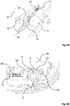
- FIG. 6A and 6B a bolt (1) inserted into the hollow quick-release axle (4) is shown, with the lock system (6) not being connected/fastened.
- the stop (2) is designed in such a way that, with the lock system (6) connected, access to the axle nut (25) with a tool is difficult or ideally not possible.
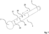
- the figure 7 shows a bolt (1) comprising a first bolt half (27) and a second bolt half (28). These can be slid telescopically in relation to one another (indicated by the double arrow), the second pin half (28) being guided in the first pin half (27).
- the displacement is only possible if the spring bolts arranged opposite one another (only one shown here) are manually pressed so far into the holes (29) that the spring bolts are no longer in the holes to grab.
- the bolt halves (27, 28) can be displaced relative to one another until the spring bolts engage in adjacent holes.
Landscapes
- Engineering & Computer Science (AREA)
- Mechanical Engineering (AREA)
- Axle Suspensions And Sidecars For Cycles (AREA)
Applications Claiming Priority (1)
| Application Number | Priority Date | Filing Date | Title |
|---|---|---|---|
| DE102021001790.0A DE102021001790B4 (de) | 2021-04-07 | 2021-04-07 | Diebstahlsicherung für Motorräder |
Publications (1)
| Publication Number | Publication Date |
|---|---|
| EP4071035A1 true EP4071035A1 (fr) | 2022-10-12 |
Family
ID=81306814
Family Applications (1)
| Application Number | Title | Priority Date | Filing Date |
|---|---|---|---|
| EP22000099.6A Withdrawn EP4071035A1 (fr) | 2021-04-07 | 2022-04-07 | Dispositif antivol pour motocycles |
Country Status (2)
| Country | Link |
|---|---|
| EP (1) | EP4071035A1 (fr) |
| DE (1) | DE102021001790B4 (fr) |
Families Citing this family (1)
| Publication number | Priority date | Publication date | Assignee | Title |
|---|---|---|---|---|
| DE102023100837A1 (de) * | 2023-01-16 | 2024-07-18 | MPR GmbH & Co. KG | Teilintegriertes System zum Anschließen eines Fahrrads |
Citations (5)
| Publication number | Priority date | Publication date | Assignee | Title |
|---|---|---|---|---|
| EP0774404A1 (fr) | 1995-11-15 | 1997-05-21 | Aprilia S.P.A. | Dispositif antivol pour véhicule à deux roues |
| DE69229785T2 (de) | 1991-08-15 | 2000-03-09 | Sherwood Enterprises International, Inc. | Motorradschloss |
| US6152541A (en) | 1996-10-31 | 2000-11-28 | Huber; Lamont C. | Quick release bicycle axle with theft-deterrent locking end cap |
| WO2002102649A1 (fr) | 2001-06-14 | 2002-12-27 | Gaston Huguenin | Dispositif antivol notamment pour un vehicule a deux roues |
| EP1559645B1 (fr) | 2004-01-28 | 2007-11-21 | Luma Industrias, S.A. | Dispositif de verrouillage du tube porte-selle de véhicules à deux roues comme des bicyclettes et des motocyclettes |
-
2021
- 2021-04-07 DE DE102021001790.0A patent/DE102021001790B4/de not_active Expired - Fee Related
-
2022
- 2022-04-07 EP EP22000099.6A patent/EP4071035A1/fr not_active Withdrawn
Patent Citations (5)
| Publication number | Priority date | Publication date | Assignee | Title |
|---|---|---|---|---|
| DE69229785T2 (de) | 1991-08-15 | 2000-03-09 | Sherwood Enterprises International, Inc. | Motorradschloss |
| EP0774404A1 (fr) | 1995-11-15 | 1997-05-21 | Aprilia S.P.A. | Dispositif antivol pour véhicule à deux roues |
| US6152541A (en) | 1996-10-31 | 2000-11-28 | Huber; Lamont C. | Quick release bicycle axle with theft-deterrent locking end cap |
| WO2002102649A1 (fr) | 2001-06-14 | 2002-12-27 | Gaston Huguenin | Dispositif antivol notamment pour un vehicule a deux roues |
| EP1559645B1 (fr) | 2004-01-28 | 2007-11-21 | Luma Industrias, S.A. | Dispositif de verrouillage du tube porte-selle de véhicules à deux roues comme des bicyclettes et des motocyclettes |
Non-Patent Citations (2)
| Title |
|---|
| PRAGMASIS LIMITED: "Anti-Pinch Pin from SecurityForBikes", 24 October 2020 (2020-10-24), XP055951093, Retrieved from the Internet <URL:https://web.archive.org/web/20201024030632/https://securityforbikes.com/anti-pinch-pin.php> [retrieved on 20220812] * |
| PRAGMASISSECURITY: "Pragmasis Anti-Pinch Pin - Fitting 16mm/19mm Chains Through Motorbikes and other Tight Spaces", 9 August 2013 (2013-08-09), XP055951096, Retrieved from the Internet <URL:https://www.youtube.com/watch?v=2lCuNUAMpWI> * |
Also Published As
| Publication number | Publication date |
|---|---|
| DE102021001790B4 (de) | 2023-01-26 |
| DE102021001790A1 (de) | 2022-10-13 |
Similar Documents
| Publication | Publication Date | Title |
|---|---|---|
| DE69229785T2 (de) | Motorradschloss | |
| DE2706242A1 (de) | Schnellentriegelungsnabe, insbesondere fuer ein fahrrad o.dgl. | |
| EP3743289B1 (fr) | Roue pour roulage à plat | |
| DE2718291A1 (de) | Diebstahlsicherung fuer kraftfahrzeuge | |
| WO1996034790A1 (fr) | Guidon et cadenas combines | |
| EP3162677A1 (fr) | Sicherungseinrichtung | |
| DE3330840A1 (de) | Absperrvorrichtung | |
| EP0541736B1 (fr) | Moyeu a serrage rapide pour bicyclettes | |
| DE3046810A1 (de) | Abschliessvorrichtung fuer zweiraeder oder aehnliche fahrzeuge | |
| DE102021001790B4 (de) | Diebstahlsicherung für Motorräder | |
| DE29610148U1 (de) | Diebstahlsicherung für Fahrräder | |
| EP0853034A2 (fr) | Dispositif anti-vol pour bicyclettes | |
| DE69603353T2 (de) | Diebstahlsicherungssystem für fahrrad | |
| DE4310590A1 (de) | Anschließvorrichtung zum Anschließen wenigstens eines Teiles eines Fahrrades | |
| DE3017879C2 (de) | Radbolzen als Diebstahlsicherung für Kraftfahrzeugräder | |
| EP0261571B1 (fr) | Dispositif de sécurité anti-vol pour véhicules | |
| EP0033936A2 (fr) | Serrure à partie pivotante pour un véhicule, en particulier une bicyclette | |
| EP0967140B1 (fr) | Antivol pour véhicule à deux ou trois roues | |
| DE10042821C2 (de) | Anschließvorrichtung für Fahrräder | |
| DE4304971A1 (de) | Radsperre | |
| EP0590257B1 (fr) | Support de bicyclettes | |
| DE4142507A1 (de) | Schnellspannabe fuer fahrraeder | |
| DE3104436A1 (de) | Schwenkbuegelschloss fuer ein fahrzeug, insbesondere ein zweiradfahrzeug | |
| DE102022122303A1 (de) | System zur Diebstahlsicherung eines Zweirads | |
| DE4011836A1 (de) | Sicherungshebel fuer kraftfahrzeuge |
Legal Events
| Date | Code | Title | Description |
|---|---|---|---|
| PUAI | Public reference made under article 153(3) epc to a published international application that has entered the european phase |
Free format text: ORIGINAL CODE: 0009012 |
|
| STAA | Information on the status of an ep patent application or granted ep patent |
Free format text: STATUS: THE APPLICATION HAS BEEN PUBLISHED |
|
| AK | Designated contracting states |
Kind code of ref document: A1 Designated state(s): AL AT BE BG CH CY CZ DE DK EE ES FI FR GB GR HR HU IE IS IT LI LT LU LV MC MK MT NL NO PL PT RO RS SE SI SK SM TR |
|
| STAA | Information on the status of an ep patent application or granted ep patent |
Free format text: STATUS: THE APPLICATION IS DEEMED TO BE WITHDRAWN |
|
| 18D | Application deemed to be withdrawn |
Effective date: 20230413 |