EP4071109A1 - Verfahren und vorrichtung zur herstellung von unlöslichem schwefel - Google Patents
Verfahren und vorrichtung zur herstellung von unlöslichem schwefel Download PDFInfo
- Publication number
- EP4071109A1 EP4071109A1 EP20908980.4A EP20908980A EP4071109A1 EP 4071109 A1 EP4071109 A1 EP 4071109A1 EP 20908980 A EP20908980 A EP 20908980A EP 4071109 A1 EP4071109 A1 EP 4071109A1
- Authority
- EP
- European Patent Office
- Prior art keywords
- pipe
- quenching
- circulating
- insoluble sulfur
- production system
- Prior art date
- Legal status (The legal status is an assumption and is not a legal conclusion. Google has not performed a legal analysis and makes no representation as to the accuracy of the status listed.)
- Granted
Links
Images
Classifications
-
- B—PERFORMING OPERATIONS; TRANSPORTING
- B01—PHYSICAL OR CHEMICAL PROCESSES OR APPARATUS IN GENERAL
- B01J—CHEMICAL OR PHYSICAL PROCESSES, e.g. CATALYSIS OR COLLOID CHEMISTRY; THEIR RELEVANT APPARATUS
- B01J19/00—Chemical, physical or physico-chemical processes in general; Their relevant apparatus
- B01J19/06—Solidifying liquids
-
- C—CHEMISTRY; METALLURGY
- C01—INORGANIC CHEMISTRY
- C01B—NON-METALLIC ELEMENTS; COMPOUNDS THEREOF; METALLOIDS OR COMPOUNDS THEREOF NOT COVERED BY SUBCLASS C01C
- C01B17/00—Sulfur; Compounds thereof
- C01B17/02—Preparation of sulfur; Purification
- C01B17/12—Insoluble sulfur (mu-sulfur)
-
- B—PERFORMING OPERATIONS; TRANSPORTING
- B01—PHYSICAL OR CHEMICAL PROCESSES OR APPARATUS IN GENERAL
- B01J—CHEMICAL OR PHYSICAL PROCESSES, e.g. CATALYSIS OR COLLOID CHEMISTRY; THEIR RELEVANT APPARATUS
- B01J19/00—Chemical, physical or physico-chemical processes in general; Their relevant apparatus
- B01J19/24—Stationary reactors without moving elements inside
- B01J19/2415—Tubular reactors
-
- C—CHEMISTRY; METALLURGY
- C01—INORGANIC CHEMISTRY
- C01B—NON-METALLIC ELEMENTS; COMPOUNDS THEREOF; METALLOIDS OR COMPOUNDS THEREOF NOT COVERED BY SUBCLASS C01C
- C01B17/00—Sulfur; Compounds thereof
- C01B17/02—Preparation of sulfur; Purification
- C01B17/0216—Solidification or cooling of liquid sulfur
-
- C—CHEMISTRY; METALLURGY
- C01—INORGANIC CHEMISTRY
- C01B—NON-METALLIC ELEMENTS; COMPOUNDS THEREOF; METALLOIDS OR COMPOUNDS THEREOF NOT COVERED BY SUBCLASS C01C
- C01B17/00—Sulfur; Compounds thereof
- C01B17/02—Preparation of sulfur; Purification
- C01B17/0232—Purification, e.g. degassing
-
- C—CHEMISTRY; METALLURGY
- C01—INORGANIC CHEMISTRY
- C01B—NON-METALLIC ELEMENTS; COMPOUNDS THEREOF; METALLOIDS OR COMPOUNDS THEREOF NOT COVERED BY SUBCLASS C01C
- C01B17/00—Sulfur; Compounds thereof
- C01B17/02—Preparation of sulfur; Purification
- C01B17/0237—Converting into particles, e.g. by granulation, milling
-
- Y—GENERAL TAGGING OF NEW TECHNOLOGICAL DEVELOPMENTS; GENERAL TAGGING OF CROSS-SECTIONAL TECHNOLOGIES SPANNING OVER SEVERAL SECTIONS OF THE IPC; TECHNICAL SUBJECTS COVERED BY FORMER USPC CROSS-REFERENCE ART COLLECTIONS [XRACs] AND DIGESTS
- Y02—TECHNOLOGIES OR APPLICATIONS FOR MITIGATION OR ADAPTATION AGAINST CLIMATE CHANGE
- Y02P—CLIMATE CHANGE MITIGATION TECHNOLOGIES IN THE PRODUCTION OR PROCESSING OF GOODS
- Y02P20/00—Technologies relating to chemical industry
- Y02P20/10—Process efficiency
Definitions
- the present invention belongs to the technical field of petrochemical industry, and relates to a production system and method for insoluble sulfur.
- Insoluble sulfur is a high-efficiency rubber vulcanizing agent, which has the advantages of high distribution stability in rubber compounds, uniform vulcanization cross-linking points of vulcanization in products, etc., and can avoid frosting on the surfaces of rubber compounds and improve the adhesion between rubber and steel wires or chemical fiber cords.
- the patent application No. CN102070127A has disclosed an insoluble sulfur production method, which comprises the following steps: (1) melt polymerization; (2) atomization and cold extraction; (3) curing; (4) centrifugal separation; (5) continuous drying; (6) crushing, screening and oil filling, so as to obtain a finished product finally; although the method is a continuous production method, the required sulfur polymerization temperature and pressure are high with the method, specifically, the operating temperature is 580-690°C, and the operating pressure is 0.8-1.2MPa; therefore, the requirements for the reaction apparatus are high.
- the patent application No. CN107337184A has disclosed heat-resistant and stable insoluble sulfur and a production method thereof.
- the production method comprises: (1) pre-melting: loading industrial raw sulfur into a sulfur melting pool at 130-150°C and pre-melting, till the raw sulfur is turned into liquid sulfur; (2) reaction: introducing the liquid sulfur into a reaction kettle, adjusting the temperature to 240°C, adding 0.6% KI, and keeping the reaction for certain time under the conditions of N 2 shielding and mechanical stirring; (3) quenching: loading the product obtained in the step (2) in a gasification chamber containing N 2 for gasification to form superheated vapor, and spraying the superheated vapor into quenching water for quenching; (4) extraction: extracting the sulfur in the quenching water with an organic solvent; (5) crushing: loading the extracted sulfur into a dryer at 45-50°C and carrying out drying till the moisture content in the sulfur is reduced to 2%-4% of the moisture content before drying, then crushing the sulfur in a tube mill, and screening the crushed suffer through
- the properties of the insoluble sulfur obtained through extruding and quenching, gas drying and curing, and mechanical crushing procedures, etc. with the existing low-temperature melting method are unsatisfactory.
- the polymerized sulfur is usually discharged by extrusion into a quenching tower for quenching.
- the quenched material is in the form of lumps, which are not easy to transport because they may cause clogging in the pipeline and equipment. Therefore, the lumps can only be transported intermittently among different devices or apparatuses, resulting in a complex system operation process.
- the present invention aims at providing an insoluble sulfur production system and a method thereof, which solve the problems of difficult solid material transportation and poor product properties, and can be used to obtain insoluble sulfur with high product purity, high thermal stability, and high yield.
- the present invention provides an insoluble sulfur production system, which comprises a polymeric kettle having a first discharge port and a quenching tower having a feed port, wherein the first discharge port is in communication with the feed port, and the quenching tower comprises a cylindrical housing, a granulation device and a shear pump, the housing comprises a feed quenching section and a discharging section that are arranged from top to bottom, and the side wall of the housing is provided with a solvent inlet for providing a solvent and a quenching agent inlet for providing a quenchant, wherein:
- the present invention provides an insoluble sulfur production method, which comprises:
- the insoluble sulfur production system can accomplish granulation, quenching, curing extraction, and crushing extraction in the quenching tower and output a slurry material.
- granulation in the granulation device after the feeding, it can ensure that the material is in a granular state in the follow-up quenching, curing and extraction process, so that the material contacts with the solvent and the quenchant extensively and can form a circulating flow along with the liquid;
- the shear pump and the filter screen ensure that the slurry material can be outputted from the second discharge port, thus avoiding clogging in the transportation pipeline during subsequent transportation;
- the granulation device, circulating pump, shear pump, inner circulating cylinder and liquid distributor etc. can realize uniform distribution of the temperature field during material quenching, as well as integrated operation of curing extraction and crushing extraction.
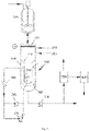
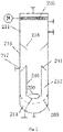
- the present invention provides an insoluble sulfur production system, which comprises a polymeric kettle 100 having a first discharge port and a quenching tower 200 having a feed port, wherein the first discharge port is in communication with the feed port, and the quenching tower 200 comprises a cylindrical housing 210, a granulation device 220 and a shear pump 230, the housing 210 comprises a feed quenching section 211 and a discharging section 213 that are arranged from top to bottom, and the side wall of the housing 210 is provided with a solvent inlet 214 for providing a solvent and a quenching agent inlet 215 for providing a quenchant respectively, wherein:
- the insoluble sulfur production system can accomplish granulation, quenching, curing extraction, and crushing extraction in the quenching tower and output a slurry material.
- granulation in the granulation device 220 after the feeding it can ensure that the material is in a granular state in the follow-up quenching, curing and extraction process, so that the material contacts with the solvent and the quenchant extensively and can form a circulating flow along with the liquid; the shear pump 230 and the filter screen 260 ensure that the slurry material can be outputted from the second discharge port, thus avoiding clogging in the inner circulating cylinder and the transportation pipeline during subsequent transportation.
- Liquid sulfur is preheated to 110-120°C and fed into the polymeric kettle 100; at the same time, an initiator is added into the polymeric kettle 100 in an amount equal to 0.05%-0.3% of the amount of the liquid sulfur.
- the material is heated to 200-270°C under nitrogen shielding for polymerization reaction, and is kept at the temperature for 30-60 minutes.
- the liquid sulfur is fed into the quenching tower 200 through the feed port; the material is granulated in the granulation device 200 first, and then the granular material (i.e., the hot sulfur granules that are formed from liquid drops and have a solid outer layer and a liquid inner core as described below) contacts with the quenchant in the quenching tower 200 (the quenchant is introduced into the quenching tower 200 through a quenching agent inlet 215, and soft water may be used as the quenchant); the hot sulfur granules are quenched and solidified in the feed quenching section 211 and for example , immersed in the quenchant in the inner circulating cylinder 240; the quenching temperature is 50-70°C; after quenching for 5-30 minutes, the quenchant is discharged from the quenching tower 200 through the second discharge port, and the solid granules formed after quenching are retained in the quenching tower 240 by the filter screen 260.
- a solvent is fed into the quenching tower 200 continuously through the quenching agent inlet 215 so as to extract the soluble sulfur continuously; after curing at 55-75°C temperature for 3-10 hours, the shear pump 230 is started to shear the sulfur granules cyclically at 45-75°C for 30-60 minutes; when the sulfur granules are in size smaller than 0.15mm, the fine sulfur granules are discharged from the second discharge port through the filter screen 260.
- quenching, curing extraction and crushing extraction can be completed without transporting the materials, and finally a slurry material containing fine granules is discharged from the second discharge port, thus the possibility of clogging in the output pipeline is greatly decreased.
- the processing time can be greatly shortened, the processing equipment and process can be simplified, and the production efficiency can be improved.
- the quenchant and solvent can be continuously inputted, while the second discharge port is kept open, so as to maintain the required processing temperature.
- the quenchant and solvent may be recycled and reused.
- the insoluble sulfur production system may comprise a cooler 300, and the housing 210 comprises a material separation section 216 for solid-liquid separation and a material circulation section 212 for circulating the materials between the feed quenching section 211 and the discharging section 213, an inner circulating cylinder 240 and a liquid distributor 250 for spraying a quenchant or solvent into the inner circulating cylinder 240 are arranged in the material circulating section 212, and a circulating liquid outlet 217 for discharging the separated liquid is arranged in the side wall of the material separating section 216, the liquid discharged from the circulating liquid outlet 217 is cooled by the cooler 300 and sent by the circulating pump 280 to the circulating inlet, which is in communication with the liquid distributor 250.
- the quenchant in the quenching tower 200 flows through the cooler 300 from the circulating liquid outlet 217 for cooling, is pressurized by the circulating pump 280 and circulated into the circulating inlet and sprayed by the liquid distributor 250 into the inner circulating cylinder 240, thereby the quenchant is recycled and reused.
- the solvent flows through the cooler 300 from the circulating liquid outlet 217 for cooling, is pressurized by the circulating pump 280 and circulated into the circulating inlet and sprayed by the liquid distributor 250 into the inner circulating cylinder 240, thereby the solvent is recycled and reused;
- the solvent flows through the cooler 300 from the circulating liquid outlet 217 for cooling, is sheared by the shear pump 230 and circulated into the circulating inlet and sprayed by the liquid distributor 250 into the inner circulating cylinder 240, thereby the solvent is recycled and reused.
- the granular material in the inner circulating cylinder 240 collides and contacts with the quenchant or solvent extensively and is formed in a fluidized state, thereby the quenching, curing and extraction can be carried out better and more quickly.
- the material separation section 216 is used to separate the granular material carried in the fluid from the liquid (e.g., the quenchant or solvent), so that the liquid discharged from the circulating liquid outlet 217 can be circulated.
- the fluid gushes from the upper end of the inner circulating cylinder 240 via the circulating pump 280, the flow rate of the fluid is decreased owing to the that the flow section is changed from the cross section of the inner circulating cylinder 240 to the cross section of the housing 210 suddenly, thus the granular material settles down under gravity action and is separated from the liquid, and the separated granular material is retained in the inner circulating cylinder 240 or falls down along the outer wall of the inner circulating cylinder 240.
- the liquid e.g., the quenchant or solvent
- a conical cylinder-shaped circulating flow guide plate 241 expanding downward gradually is arranged on the periphery at the top of the inner circulating cylinder 240, and clearance exists between the circulating flow guide plate 241 and the inner wall of the housing 210.
- the radius of the lower end of the circulating flow guide plate 241 is 0.5-0.9 times of the radius of the housing 210, so as to maintain appropriate clearance.
- the lower end of the circulating flow guide plate 241 is located below the circulating liquid outlet 217, so as to prevent the granular material from entering the circulating liquid outlet 217 when the quenchant or solvent is circulated.
- a conical cylinder-shaped material flow guide plate 218 tapered toward the inner circulating cylinder 240 may be arranged on the inner wall of the material separation section 216.
- the material flow guide plate 218 is located above the circulating liquid outlet 217.
- the material flow guide plate 218 is arranged in at least one of the following forms:
- the corresponding components and parameters of the material circulation section 212 and the discharging section 213 may be set to retain the material in the material circulation section 212 and the discharging section 213 for a required duration; preferably, the insoluble sulfur production system is configured in at least one of the following forms:
- the solvent inlet 214 and the quenching agent inlet 215 may be arranged at appropriate positions of the housing 210, and may be connected to corresponding external storage devices through corresponding pipelines.
- the solvent inlet 214 and the quenching agent inlet 215 may be arranged in the side wall of the feed quenching section 211, so as to avoid interference with the operation of other sections (e.g., the material separation section 216).
- the granulation device 220 may be in any appropriate form, as long as the material entrying from the feed port can be formed into granular material.
- the material fed from the feed port is usually in a liquid state in which the material is drawn and difficult to granulate; the granulation device 220 may be arranged to separate and granulate the material into a droplet-shaped granular material (also referred to as droplet material).
- the granulation device 220 comprises a first feed pipe 221 in communication with the feed port and a first distribution pipe 222 in communication with the first feed pipe 221
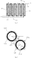
- the first distribution pipe 222 comprises a first fixed pipe 2221 and a first rotary pipe 2222 that is sleeved on the first fixed pipe 2221 and can rotate with respect to the first fixed pipe 2221
- the pipe wall of the first fixed pipe 2221 is provided with a first discharge channel 2223 extending in the axial direction
- the pipe wall of the first rotary pipe 2222 is provided with multiple groups of first discharge holes 2224 that can correspond to the first discharge channel 2223
- each group of first discharge holes 2224 are arranged in the axial direction
- the multiple groups of first discharge holes 2224 are distributed in the circumferential direction of the first rotary pipe 2222.
- the material fed from the feed port flows through the first feed pipe 221 into the first fixed pipe 2221, and is rotated upward through the first rotary pipe 2222 to the first discharge holes 2224 aligned to the first discharge channel 2223 and then discharged.
- the first rotary pipe 2222 is rotated with respect to the first fixed pipe 2221, so as to discharge the material intermittently through different first discharge holes 2224; thus the material can be cut by means of the counter-rotation to form a droplet material corresponding to the shape of the first discharge holes 2224 and realize granulation.
- the shape and parameters of the first discharge holes 2224 may be arranged appropriately; preferably, the first discharge holes 2224 may be in size of 0.5-3mm, and the spacing between adjacent first discharge holes 2224 in the same group may be 3-15mm.
- the size of the first discharge holes 2224 refers to the maximum dimension of the shape contour, and may vary depending on the shape of the first discharge holes 2224. For example, in the case of circular first discharge holes 2224, the size is the diameter; for elliptical first discharge holes 2224, the size is the major diameter of the ellipse; for rectangular first discharge holes 2224, the size is the length of the longer side.
- a distributor for uniformly distributing the quenchant may be arranged in the feed quenching section 211.
- a distributor for uniformly distributing the quenchant may be arranged in the feed quenching section 211.
- the feed quenching section 221 is provided with a quenchant distributor 270, which comprises a second feed pipe 271 in communication with the quenching agent inlet 215 and a second distribution pipe 272 in communication with the second feed pipe 271, wherein the second distribution pipe 272 is arranged in parallel to the first distribution pipe 222 , the setting height of the second distribution pipe 272 is lower than the first distribution pipe 222, and the second distribution pipe 272 comprises a second fixed pipe 2721 and a second rotary pipe 2722 that is sleeved on the second fixed pipe 2721 and can rotate with respect to the second fixed pipe 2721, the pipe wall of the second fixed pipe 2721 is provided with a second discharge channel 2723 extending in the axial direction, the pipe wall of the second rotary pipe 2722 is provided with multiple second discharge holes 2724 that can correspond to the second discharge channel 2723 and are distributed in the circumferential direction of the second rotary pipe 2722, the outer wall of the second rotary pipe 2722 is provided with a doctor blade 273 that can
- the quenchant flows through the second feed pipe 271 into the second fixed pipe 2721, and is rotated upward by the second rotary pipe 2722 to the second discharge holes 2724 aligned to the second discharge channel 2723 and then discharged.
- each second discharge hole 2724 comprises a plurality of slits extending in the axial direction sequentially, and each slit is in 5-20mm width; and/or the second discharge holes 2724 are configured to provide the quenchant in the tangential direction of the second rotary pipe 2722.
- the jetted quenchant will not contact immediately with the droplet material discharged from the first discharge holes 2224 and cause clogging of the first discharge holes 2224 by the droplets chilled suddenly.
- the first discharge channel 2223 By orienting the first discharge channel 2223 toward the second distribution pipe 272 (i.e., the first discharge channel 2223 is located between the first rotary pipe 2222 and the second rotary pipe 2722, preferably the first discharge channel 2223 is located in a connecting line between the centers of circles of the first rotary pipe 2222 and the second rotary pipe 2722 on the same cross section), when the second rotary pipe 2722 is rotated, it can come into contact with the outer wall of the first rotary pipe 2222 through the doctor blade 273 , thereby on one hand the drawn material can be cut into a droplet shape thoroughly to facilitate granulation, and on the other hand the material on the outer ends of the first discharge holes 2224 can be scraped off, so as to prevent the drawn material from adhering to the first discharge holes 2224 and prevent clogging of the first discharge holes 2224 incurred by the chilling of the material exposed to a low-temperature environment, thereby solve the problem that it is difficult to granulate the high-viscosity drawn material.
- the doctor blade 273 is preferably arranged to pass by the outer ends of the first discharge holes 2224 in a tangential manner.
- the doctor blade 273 is an elastic doctor blade.
- the doctor blade 273 may be dimensioned so that it extends beyond the minimum clearance between the first rotary pipe 2222 and the second rotary pipe 2722, thereby the doctor blade 273 is deformed elastically to have a portion essentially in the tangential direction of the first rotary pipe 2222 when the doctor blade 273 comes into contact with the first rotary pipe 2222, thereby the material is scraped off by that portion.
- the doctor blade may be made of a material to which the sulfur material can't adhere easily, in order to avoid adherence of the sulfur material to the doctor blade.
- the doctor blade 273 is a stainless steel blade to make the requirements for elasticity and non-adherence.
- the cooling of the droplet material discharged from the first discharge holes 2224 starts from the moment the droplet material leaves the first discharge holes 2224 to form into hot sulfur granules that have a solid outer layer and a liquid inner core; then the droplets contact with the quenchant extensively in the falling process in the quenching tower, and finally fall into the inner circulating cylinder 240 and are immersed in the quenchant and cooled into solid granules.
- the first distribution pipe 222 and the second distribution pipe 272 are a plurality of distribution pipes that are arranged corresponding to each other alternatively, the plurality of first distribution pipes 222 are arranged side by side, the plurality of second distribution pipes 272 are arranged side by side, and a connecting line between the centers of cross sections of a first distribution pipe 222 and a corresponding second distribution pipe 272 in the same plane is at 40-50° with respect to the plane of arrangement of the first distribution pipes 222.
- the first distribution pipe 222 and the second distribution pipe 272 may be rake-formed distribution pipes and arranged in the transverse direction of the feed quenching section 211, so as to distribute the material and the quenchant uniformly on the entire cross section of the feed quenching section 211.
- the rotation axis of the first rotary pipe 2222 is parallel to that of the second rotary pipe 2722, so that the first rotary pipe 2222 and the second rotary pipe 2722 can be rotated by the same driving device.
- the first rotary pipe 2222 and the second rotary pipe 2722 may be connected to the driving device via a transmission device respectively.
- the first rotary pipe 2222 and the second rotary pipe 2722 preferably rotate in the same direction, so as to improve the scraping effect of the doctor blade 273.
- the insoluble sulfur production system may comprise a washing filter 500 and a dryer 600, and the inlet and outlet of the washing filter 500 are in communication with the second discharge port and the dryer 600 respectively.
- the washing filter 500 and the second discharge port may be connected through a pipeline between them, and transportation pressure may be provided in the pipeline by means of the discharge pump 700.
- the slurry material discharged from the discharge port may be conveniently sent to the washing filter 500 by the discharge pump 700 for further washing, extraction and filtration treatment, and the washing and filtering solvent may be recycled through a separate pipeline.
- the washing and filtration temperature is 65-95°C, and the washing and filtration operation is carried out continuously for 2-4 times.
- the insoluble sulfur obtained through filtration enters the dryer 600, for vacuum drying at 65-95°C drying temperature for 1-5 hours at 100-1,000Pa drying vacuum degree, thus an insoluble sulfur product is obtained after the drying.
- the granulation device 220, circulating pump 280, shear pump 230, inner circulating cylinder 240 and liquid distributor 250 etc. can realize uniform distribution of the temperature field during material quenching, as well as integrated operation of curing extraction and crushing extraction.
- the present invention provides an insoluble sulfur production method, which comprises:
- the insoluble sulfur production method provided by the present invention can accomplish granulation, quenching, curing extraction, and crushing extraction sequentially in the quenching tower and output a slurry material.
- granulation after the feeding it can ensure that the material is in a granular state in the follow-up quenching, curing and extraction process, so that the material contacts with the solvent and the quenchant extensively and can form a circulating flow along with the liquid;
- a slurry material can be obtained by liquid-phase circulated crushing, so as to avoid clogging in the transportation pipeline during subsequent transportation;
- the granulation device, circulating pump, shear pump, inner circulating cylinder and liquid distributor etc. can realize uniform distribution of the temperature field during material quenching, as well as integrated operation of curing extraction and crushing extraction.
- the liquid-phase circulated crushing may be carried out in an appropriate way, for example, by using a shear pump.
- the slurry material may be filtered when it is outputted.
- the method comprises: S5. outputting the slurry obtained through liquid-phase circulated crushing from the quenching tower for washing filtration; S6. drying the solid product obtained through washing filtration to obtain an insoluble sulfur product.
- the slurry material discharged from the quenching tower may be conveniently sent to, for example, the washing filter 500 for further washing, extraction and filtration treatment, and the washing and filtering solvent may be recycled through a separate pipeline.
- the washing and filtration temperature is 65-95°C, and the washing and filtration operation is carried out continuously for 2-4 times.
- the insoluble sulfur obtained through filtration enters, for example, a dryer 600, for vacuum drying at 65-95°C drying temperature for 1-5 hours at 100-1,000Pa drying vacuum degree, thus an insoluble sulfur product is obtained after the drying.
- the polymerization temperature may be 200-270°C, preferably 250-260°C; and the polymerization duration may be 30-60 minutes, preferably 30-45 minutes.
- the initiator may be one or more of potassium persulfate, dimethyl sulfoxide, etc.
- the feed amount of the initiator is 0.05wt%-0.3wt%, preferably 0.1wt%-0.2wt% of the feed amount of the liquid sulfur.
- the quenching temperature may be 50-70°C, preferably 55-65°C; and the quenching duration may be 5-30 minutes, preferably 10-20 minutes.
- the quenchant may be soft water.
- the solvent used in the curing, washing and filtering process may be one or more of cyclohexane, benzene, paraxylene, etc., preferably is paraxylene.
- the curing temperature may be 55-75°C, preferably 60-65°C; the curing duration may be 3-10 hours, preferably 5-9 hours.
- the extraction agent may be used as the curing solvent, so as to carry out sulfur granule curing and extraction at the same time; thus, compared with the conventional low-temperature melting method, the curing time is shortened, a quenchant drying process can be avoided, the technical process is greatly shortened, the process flow is simplified, and the production efficiency is improved.
- the processing temperature of the liquid-phase circulated crushing may be 45-75°C, preferably 50-60°C, the processing time may be 30-60 minutes, preferably 35-50 minutes, and the granularity of the granules after the crushing may be 100-250mpi, preferably 120-200mpi.
- the extraction agent may be used as the solvent for the liquid-phase circulated crushing, and sulfur granule crushing and extraction are carried out at the same time; compared with the conventional dry mechanical crushing method, the adverse effect of increased material temperature on the product quality during the crushing can be avoided.
- the temperature of washing filtration may be 65-95°C, preferably 70-85°C, and the washing filtration is carried out continuously for 2-4 times, preferably 2-3 times.
- the drying may be vacuum drying
- the drying temperature may be 65-95°C, preferably 70-85°C
- the drying duration may be 1-5 hours, preferably 35-50 minutes
- the vacuum degree of drying may be 100-1,000Pa, preferably 200-500Pa.
- the method in the present invention may be implemented with the insoluble sulfur production system provided by the present invention.
Landscapes
- Chemical & Material Sciences (AREA)
- Organic Chemistry (AREA)
- Inorganic Chemistry (AREA)
- Chemical Kinetics & Catalysis (AREA)
- Organic Low-Molecular-Weight Compounds And Preparation Thereof (AREA)
- Polymers With Sulfur, Phosphorus Or Metals In The Main Chain (AREA)
Applications Claiming Priority (2)
| Application Number | Priority Date | Filing Date | Title |
|---|---|---|---|
| CN201911418296.8A CN113120869B (zh) | 2019-12-31 | 2019-12-31 | 一种不溶性硫磺生产方法和生产系统 |
| PCT/CN2020/140097 WO2021136160A1 (zh) | 2019-12-31 | 2020-12-28 | 不溶性硫磺生产系统和生产方法 |
Publications (3)
| Publication Number | Publication Date |
|---|---|
| EP4071109A1 true EP4071109A1 (de) | 2022-10-12 |
| EP4071109A4 EP4071109A4 (de) | 2023-05-24 |
| EP4071109B1 EP4071109B1 (de) | 2024-10-30 |
Family
ID=76687535
Family Applications (1)
| Application Number | Title | Priority Date | Filing Date |
|---|---|---|---|
| EP20908980.4A Active EP4071109B1 (de) | 2019-12-31 | 2020-12-28 | Verfahren und vorrichtung zur herstellung von unlöslichem schwefel |
Country Status (4)
| Country | Link |
|---|---|
| US (1) | US12465903B2 (de) |
| EP (1) | EP4071109B1 (de) |
| CN (1) | CN113120869B (de) |
| WO (1) | WO2021136160A1 (de) |
Families Citing this family (6)
| Publication number | Priority date | Publication date | Assignee | Title |
|---|---|---|---|---|
| CN116062706B (zh) * | 2021-10-31 | 2025-02-28 | 中国石油化工股份有限公司 | 一种高性能不溶性硫磺湿式生产系统和方法 |
| CN116062707B (zh) * | 2021-10-31 | 2024-12-06 | 中国石油化工股份有限公司 | 一种低温熔融法不溶性硫磺生产系统和方法 |
| CN116062704B (zh) * | 2021-10-31 | 2025-10-03 | 中国石油化工股份有限公司 | 一种低温熔融法生产不溶性硫磺急冷分级系统和方法 |
| CN113860268A (zh) * | 2021-11-18 | 2021-12-31 | 常州工学院 | 一种不溶性硫磺连续生产筛分罐及其加工方法 |
| CN116477581B (zh) * | 2022-01-15 | 2024-12-06 | 中国石油化工股份有限公司 | 一种不溶性硫磺一体化生产设备和方法 |
| CN116534804B (zh) * | 2023-05-31 | 2024-05-24 | 湖南化工设计院有限公司 | 一种高纯度硫磺的提取系统 |
Family Cites Families (28)
| Publication number | Priority date | Publication date | Assignee | Title |
|---|---|---|---|---|
| RU2107657C1 (ru) | 1997-04-11 | 1998-03-27 | Вячеслав Александрович Чиндяскин | Способ получения нерастворимой серы и устройство для его осуществления |
| RU2177825C1 (ru) | 2000-07-20 | 2002-01-10 | Общество с ограниченной ответственностью "Астраханьгазпром" | Установка для получения гранулированной серы |
| CN1241830C (zh) | 2003-06-04 | 2006-02-15 | 中国科学院大连化学物理研究所 | 一种制备不溶性硫磺的方法 |
| DE10333374A1 (de) * | 2003-07-23 | 2005-02-10 | Bayer Aktiengesellschaft | Verfahren zur Herstellung von polymerem Schwefel |
| CN2672030Y (zh) * | 2003-12-31 | 2005-01-19 | 王桃仙 | 用于液相或汽相法生产不溶性硫磺的萃取釜 |
| CN100427386C (zh) * | 2005-12-22 | 2008-10-22 | 南化集团研究院 | 中品位不溶性硫磺的制备方法及其生产设备 |
| CN101066753B (zh) * | 2007-05-29 | 2010-06-02 | 江西恒兴源化工有限公司 | 连续一步法制造不溶性硫磺的方法 |
| CN102070127B (zh) | 2011-02-17 | 2012-07-18 | 四川晨辉化工有限公司 | 一种不溶性硫磺的生产方法 |
| CN102951615B (zh) * | 2011-08-29 | 2016-08-17 | 江苏圣奥化学科技有限公司 | 生产不溶性硫磺的处理罐 |
| CN102976281A (zh) * | 2011-09-02 | 2013-03-20 | 台州学院 | 一种不溶性硫磺的制备方法 |
| CN104843651A (zh) * | 2014-02-18 | 2015-08-19 | 中国石油化工股份有限公司 | 一种低温法制备不溶性硫磺的生产工艺 |
| CN204295905U (zh) * | 2014-12-04 | 2015-04-29 | 倪平 | 一种自动化开炼机 |
| CN105502303A (zh) * | 2016-01-22 | 2016-04-20 | 上海京海(安徽)化工有限公司 | 一种制备高热稳定性高含量不溶性硫磺的生产工艺 |
| CN105694096A (zh) * | 2016-01-29 | 2016-06-22 | 常州达奥新材料科技有限公司 | 一种高分散不溶性硫磺的环保制备方法 |
| CN206172977U (zh) * | 2016-11-14 | 2017-05-17 | 中国石油化工股份有限公司 | 一种不溶性硫磺的生产系统 |
| CN206799166U (zh) * | 2016-11-14 | 2017-12-26 | 中国石油化工股份有限公司 | 一种不溶性硫磺的生产系统 |
| RU2645134C1 (ru) | 2016-11-15 | 2018-02-15 | Общество с ограниченной ответственностью "Газпром переработка" | Устройство для гранулирования жидкой серы |
| CN106892410B (zh) * | 2017-04-25 | 2022-12-30 | 中国石油大学(华东) | 一种不溶性硫磺的生产方法 |
| CN106946230B (zh) * | 2017-04-25 | 2023-01-17 | 中国石油大学(华东) | 一种不溶性硫磺的连续生产方法 |
| CN107337184A (zh) * | 2017-09-01 | 2017-11-10 | 上海京海(安徽)化工有限公司 | 一种耐热稳定不溶性硫磺及其生产方法 |
| CN207435026U (zh) | 2017-11-14 | 2018-06-01 | 浙江海洋大学 | 一种具有快速急冷雾化作用的不溶性硫磺淬冷装置 |
| CN207628144U (zh) * | 2017-12-12 | 2018-07-20 | 神华集团有限责任公司 | 含固烃类气体冷却净化装置 |
| CN208071319U (zh) * | 2018-03-20 | 2018-11-09 | 朝阳明宇化工有限公司 | 一种不溶性硫磺安全生产的气化淬冷设备 |
| CN108383088B (zh) | 2018-04-28 | 2023-12-15 | 上海京海(安徽)化工有限公司 | 一种不溶性硫磺的生产系统及生产方法 |
| CN209204988U (zh) * | 2018-10-30 | 2019-08-06 | 金川集团股份有限公司 | 一种多单元高效洗涤塔 |
| CN109336061B (zh) | 2018-11-15 | 2021-12-14 | 东营市海科瑞林化工有限公司 | 一种提高不溶性硫磺生产过程中淬冷效果的生产装置及其生产系统 |
| CN209555166U (zh) * | 2019-01-30 | 2019-10-29 | 中国科学院广州能源研究所 | 一种高湿生物质气化系统 |
| CN209555167U (zh) * | 2019-01-30 | 2019-10-29 | 中国科学院广州能源研究所 | 一种焦油净化处理的系统 |
-
2019
- 2019-12-31 CN CN201911418296.8A patent/CN113120869B/zh active Active
-
2020
- 2020-12-28 EP EP20908980.4A patent/EP4071109B1/de active Active
- 2020-12-28 US US17/758,287 patent/US12465903B2/en active Active
- 2020-12-28 WO PCT/CN2020/140097 patent/WO2021136160A1/zh not_active Ceased
Also Published As
| Publication number | Publication date |
|---|---|
| CN113120869B (zh) | 2023-01-10 |
| US12465903B2 (en) | 2025-11-11 |
| EP4071109A4 (de) | 2023-05-24 |
| EP4071109B1 (de) | 2024-10-30 |
| CN113120869A (zh) | 2021-07-16 |
| US20230035805A1 (en) | 2023-02-02 |
| WO2021136160A1 (zh) | 2021-07-08 |
Similar Documents
| Publication | Publication Date | Title |
|---|---|---|
| EP4071109B1 (de) | Verfahren und vorrichtung zur herstellung von unlöslichem schwefel | |
| JP5591111B2 (ja) | 高粘度ポリエステル溶融物でできた低加水分解性ポリエステル顆粒の製造方法、および該ポリエステル顆粒の製造装置 | |
| CN113120868B (zh) | 一种不溶性硫磺生产方法和系统 | |
| CN113120870B (zh) | 高性能不溶性硫磺生产系统和方法 | |
| US20150266209A1 (en) | Method and apparatus for increasing the intrinsic viscosity of a polycondensate melt | |
| US4092784A (en) | Process and apparatus for drying and heating nylon granules | |
| CN108570148B (zh) | 一种防氧化的尼龙6切片聚合生产装置及方法 | |
| US3267074A (en) | Process for producing polycarbonates | |
| EP1441885A1 (de) | Verfahren und vorrichtung zur erhöhung der grenzviskosität von polyester | |
| CN113120867B (zh) | 一种不溶性硫磺加工方法和加工系统 | |
| CN111377411B (zh) | 一种不溶性硫磺生产方法和生产系统 | |
| CN107667132B (zh) | 可结晶热塑性材料的颗粒的结晶并从该颗粒中分离低分子组分的方法及其装置 | |
| RU2800442C1 (ru) | Система и способ получения нерастворимой серы | |
| CN111377412B (zh) | 一种不溶性硫磺连续淬冷装置 | |
| CN114436220B (zh) | 一种低温熔融法生产不溶性硫磺淬冷系统和方法 | |
| CN208632436U (zh) | 一种防氧化的尼龙6切片聚合生产装置 | |
| EP4065330B1 (de) | Verfahren und vorrichtung zur produktion von polyamid-6-pellets | |
| US10584204B2 (en) | Process and device for producing polyamides, with optimized flow guidance | |
| CN114292660B (zh) | 一种沥青成型进料器装置及工艺方法 | |
| DE1905919C3 (de) | Verfahren und Vorrichtung zur kontinuierlichen Herstellung von Polyvinylacetat oder Polystyrol | |
| SU753455A1 (ru) | Способ гранулировани смол и устройство дл его осуществлени |
Legal Events
| Date | Code | Title | Description |
|---|---|---|---|
| STAA | Information on the status of an ep patent application or granted ep patent |
Free format text: STATUS: THE INTERNATIONAL PUBLICATION HAS BEEN MADE |
|
| PUAI | Public reference made under article 153(3) epc to a published international application that has entered the european phase |
Free format text: ORIGINAL CODE: 0009012 |
|
| STAA | Information on the status of an ep patent application or granted ep patent |
Free format text: STATUS: REQUEST FOR EXAMINATION WAS MADE |
|
| 17P | Request for examination filed |
Effective date: 20220705 |
|
| AK | Designated contracting states |
Kind code of ref document: A1 Designated state(s): AL AT BE BG CH CY CZ DE DK EE ES FI FR GB GR HR HU IE IS IT LI LT LU LV MC MK MT NL NO PL PT RO RS SE SI SK SM TR |
|
| DAV | Request for validation of the european patent (deleted) | ||
| DAX | Request for extension of the european patent (deleted) | ||
| A4 | Supplementary search report drawn up and despatched |
Effective date: 20230421 |
|
| RIC1 | Information provided on ipc code assigned before grant |
Ipc: C01B 17/02 20060101ALI20230417BHEP Ipc: C01B 17/12 20060101AFI20230417BHEP |
|
| STAA | Information on the status of an ep patent application or granted ep patent |
Free format text: STATUS: EXAMINATION IS IN PROGRESS |
|
| 17Q | First examination report despatched |
Effective date: 20231128 |
|
| GRAP | Despatch of communication of intention to grant a patent |
Free format text: ORIGINAL CODE: EPIDOSNIGR1 |
|
| STAA | Information on the status of an ep patent application or granted ep patent |
Free format text: STATUS: GRANT OF PATENT IS INTENDED |
|
| INTG | Intention to grant announced |
Effective date: 20240619 |
|
| GRAS | Grant fee paid |
Free format text: ORIGINAL CODE: EPIDOSNIGR3 |
|
| GRAA | (expected) grant |
Free format text: ORIGINAL CODE: 0009210 |
|
| STAA | Information on the status of an ep patent application or granted ep patent |
Free format text: STATUS: THE PATENT HAS BEEN GRANTED |
|
| AK | Designated contracting states |
Kind code of ref document: B1 Designated state(s): AL AT BE BG CH CY CZ DE DK EE ES FI FR GB GR HR HU IE IS IT LI LT LU LV MC MK MT NL NO PL PT RO RS SE SI SK SM TR |
|
| REG | Reference to a national code |
Ref country code: GB Ref legal event code: FG4D |
|
| REG | Reference to a national code |
Ref country code: CH Ref legal event code: EP |
|
| REG | Reference to a national code |
Ref country code: IE Ref legal event code: FG4D |
|
| REG | Reference to a national code |
Ref country code: DE Ref legal event code: R096 Ref document number: 602020040582 Country of ref document: DE |
|
| REG | Reference to a national code |
Ref country code: LT Ref legal event code: MG9D |
|
| REG | Reference to a national code |
Ref country code: NL Ref legal event code: MP Effective date: 20241030 |
|
| PG25 | Lapsed in a contracting state [announced via postgrant information from national office to epo] |
Ref country code: PT Free format text: LAPSE BECAUSE OF FAILURE TO SUBMIT A TRANSLATION OF THE DESCRIPTION OR TO PAY THE FEE WITHIN THE PRESCRIBED TIME-LIMIT Effective date: 20250228 Ref country code: HR Free format text: LAPSE BECAUSE OF FAILURE TO SUBMIT A TRANSLATION OF THE DESCRIPTION OR TO PAY THE FEE WITHIN THE PRESCRIBED TIME-LIMIT Effective date: 20241030 Ref country code: IS Free format text: LAPSE BECAUSE OF FAILURE TO SUBMIT A TRANSLATION OF THE DESCRIPTION OR TO PAY THE FEE WITHIN THE PRESCRIBED TIME-LIMIT Effective date: 20250228 |
|
| PG25 | Lapsed in a contracting state [announced via postgrant information from national office to epo] |
Ref country code: FI Free format text: LAPSE BECAUSE OF FAILURE TO SUBMIT A TRANSLATION OF THE DESCRIPTION OR TO PAY THE FEE WITHIN THE PRESCRIBED TIME-LIMIT Effective date: 20241030 Ref country code: NL Free format text: LAPSE BECAUSE OF FAILURE TO SUBMIT A TRANSLATION OF THE DESCRIPTION OR TO PAY THE FEE WITHIN THE PRESCRIBED TIME-LIMIT Effective date: 20241030 |
|
| REG | Reference to a national code |
Ref country code: AT Ref legal event code: MK05 Ref document number: 1736749 Country of ref document: AT Kind code of ref document: T Effective date: 20241030 |
|
| PG25 | Lapsed in a contracting state [announced via postgrant information from national office to epo] |
Ref country code: BG Free format text: LAPSE BECAUSE OF FAILURE TO SUBMIT A TRANSLATION OF THE DESCRIPTION OR TO PAY THE FEE WITHIN THE PRESCRIBED TIME-LIMIT Effective date: 20241030 |
|
| PG25 | Lapsed in a contracting state [announced via postgrant information from national office to epo] |
Ref country code: ES Free format text: LAPSE BECAUSE OF FAILURE TO SUBMIT A TRANSLATION OF THE DESCRIPTION OR TO PAY THE FEE WITHIN THE PRESCRIBED TIME-LIMIT Effective date: 20241030 |
|
| P01 | Opt-out of the competence of the unified patent court (upc) registered |
Free format text: CASE NUMBER: APP_13388/2025 Effective date: 20250318 |
|
| PG25 | Lapsed in a contracting state [announced via postgrant information from national office to epo] |
Ref country code: NO Free format text: LAPSE BECAUSE OF FAILURE TO SUBMIT A TRANSLATION OF THE DESCRIPTION OR TO PAY THE FEE WITHIN THE PRESCRIBED TIME-LIMIT Effective date: 20250130 |
|
| PG25 | Lapsed in a contracting state [announced via postgrant information from national office to epo] |
Ref country code: GR Free format text: LAPSE BECAUSE OF FAILURE TO SUBMIT A TRANSLATION OF THE DESCRIPTION OR TO PAY THE FEE WITHIN THE PRESCRIBED TIME-LIMIT Effective date: 20250131 Ref country code: LV Free format text: LAPSE BECAUSE OF FAILURE TO SUBMIT A TRANSLATION OF THE DESCRIPTION OR TO PAY THE FEE WITHIN THE PRESCRIBED TIME-LIMIT Effective date: 20241030 Ref country code: AT Free format text: LAPSE BECAUSE OF FAILURE TO SUBMIT A TRANSLATION OF THE DESCRIPTION OR TO PAY THE FEE WITHIN THE PRESCRIBED TIME-LIMIT Effective date: 20241030 |
|
| PG25 | Lapsed in a contracting state [announced via postgrant information from national office to epo] |
Ref country code: PL Free format text: LAPSE BECAUSE OF FAILURE TO SUBMIT A TRANSLATION OF THE DESCRIPTION OR TO PAY THE FEE WITHIN THE PRESCRIBED TIME-LIMIT Effective date: 20241030 |
|
| PG25 | Lapsed in a contracting state [announced via postgrant information from national office to epo] |
Ref country code: RS Free format text: LAPSE BECAUSE OF FAILURE TO SUBMIT A TRANSLATION OF THE DESCRIPTION OR TO PAY THE FEE WITHIN THE PRESCRIBED TIME-LIMIT Effective date: 20250130 |
|
| PG25 | Lapsed in a contracting state [announced via postgrant information from national office to epo] |
Ref country code: SM Free format text: LAPSE BECAUSE OF FAILURE TO SUBMIT A TRANSLATION OF THE DESCRIPTION OR TO PAY THE FEE WITHIN THE PRESCRIBED TIME-LIMIT Effective date: 20241030 |
|
| PG25 | Lapsed in a contracting state [announced via postgrant information from national office to epo] |
Ref country code: MC Free format text: LAPSE BECAUSE OF FAILURE TO SUBMIT A TRANSLATION OF THE DESCRIPTION OR TO PAY THE FEE WITHIN THE PRESCRIBED TIME-LIMIT Effective date: 20241030 |
|
| PG25 | Lapsed in a contracting state [announced via postgrant information from national office to epo] |
Ref country code: DK Free format text: LAPSE BECAUSE OF FAILURE TO SUBMIT A TRANSLATION OF THE DESCRIPTION OR TO PAY THE FEE WITHIN THE PRESCRIBED TIME-LIMIT Effective date: 20241030 |
|
| PG25 | Lapsed in a contracting state [announced via postgrant information from national office to epo] |
Ref country code: EE Free format text: LAPSE BECAUSE OF FAILURE TO SUBMIT A TRANSLATION OF THE DESCRIPTION OR TO PAY THE FEE WITHIN THE PRESCRIBED TIME-LIMIT Effective date: 20241030 |
|
| PG25 | Lapsed in a contracting state [announced via postgrant information from national office to epo] |
Ref country code: RO Free format text: LAPSE BECAUSE OF FAILURE TO SUBMIT A TRANSLATION OF THE DESCRIPTION OR TO PAY THE FEE WITHIN THE PRESCRIBED TIME-LIMIT Effective date: 20241030 |
|
| PG25 | Lapsed in a contracting state [announced via postgrant information from national office to epo] |
Ref country code: SK Free format text: LAPSE BECAUSE OF FAILURE TO SUBMIT A TRANSLATION OF THE DESCRIPTION OR TO PAY THE FEE WITHIN THE PRESCRIBED TIME-LIMIT Effective date: 20241030 |
|
| PG25 | Lapsed in a contracting state [announced via postgrant information from national office to epo] |
Ref country code: CZ Free format text: LAPSE BECAUSE OF FAILURE TO SUBMIT A TRANSLATION OF THE DESCRIPTION OR TO PAY THE FEE WITHIN THE PRESCRIBED TIME-LIMIT Effective date: 20241030 |
|
| PG25 | Lapsed in a contracting state [announced via postgrant information from national office to epo] |
Ref country code: IT Free format text: LAPSE BECAUSE OF FAILURE TO SUBMIT A TRANSLATION OF THE DESCRIPTION OR TO PAY THE FEE WITHIN THE PRESCRIBED TIME-LIMIT Effective date: 20241030 |
|
| REG | Reference to a national code |
Ref country code: CH Ref legal event code: PL Ref country code: DE Ref legal event code: R097 Ref document number: 602020040582 Country of ref document: DE |
|
| PG25 | Lapsed in a contracting state [announced via postgrant information from national office to epo] |
Ref country code: LU Free format text: LAPSE BECAUSE OF NON-PAYMENT OF DUE FEES Effective date: 20241228 |
|
| PLBE | No opposition filed within time limit |
Free format text: ORIGINAL CODE: 0009261 |
|
| STAA | Information on the status of an ep patent application or granted ep patent |
Free format text: STATUS: NO OPPOSITION FILED WITHIN TIME LIMIT |
|
| PG25 | Lapsed in a contracting state [announced via postgrant information from national office to epo] |
Ref country code: SE Free format text: LAPSE BECAUSE OF FAILURE TO SUBMIT A TRANSLATION OF THE DESCRIPTION OR TO PAY THE FEE WITHIN THE PRESCRIBED TIME-LIMIT Effective date: 20241030 |
|
| 26N | No opposition filed |
Effective date: 20250731 |
|
| REG | Reference to a national code |
Ref country code: BE Ref legal event code: MM Effective date: 20241231 |
|
| PG25 | Lapsed in a contracting state [announced via postgrant information from national office to epo] |
Ref country code: BE Free format text: LAPSE BECAUSE OF NON-PAYMENT OF DUE FEES Effective date: 20241231 |
|
| PG25 | Lapsed in a contracting state [announced via postgrant information from national office to epo] |
Ref country code: CH Free format text: LAPSE BECAUSE OF NON-PAYMENT OF DUE FEES Effective date: 20241231 |
|
| PG25 | Lapsed in a contracting state [announced via postgrant information from national office to epo] |
Ref country code: IE Free format text: LAPSE BECAUSE OF NON-PAYMENT OF DUE FEES Effective date: 20241228 |
|
| PGFP | Annual fee paid to national office [announced via postgrant information from national office to epo] |
Ref country code: DE Payment date: 20250930 Year of fee payment: 6 |
|
| PGFP | Annual fee paid to national office [announced via postgrant information from national office to epo] |
Ref country code: GB Payment date: 20251001 Year of fee payment: 6 |
|
| PGFP | Annual fee paid to national office [announced via postgrant information from national office to epo] |
Ref country code: FR Payment date: 20251110 Year of fee payment: 6 |