EP4071586A1 - Commande sans contact des appareils médicaux - Google Patents
Commande sans contact des appareils médicaux Download PDFInfo
- Publication number
- EP4071586A1 EP4071586A1 EP21167557.4A EP21167557A EP4071586A1 EP 4071586 A1 EP4071586 A1 EP 4071586A1 EP 21167557 A EP21167557 A EP 21167557A EP 4071586 A1 EP4071586 A1 EP 4071586A1
- Authority
- EP
- European Patent Office
- Prior art keywords
- signal
- pointing
- mobile
- pointing device
- mobile pointing
- Prior art date
- Legal status (The legal status is an assumption and is not a legal conclusion. Google has not performed a legal analysis and makes no representation as to the accuracy of the status listed.)
- Withdrawn
Links
Images

Classifications
-
- G—PHYSICS
- G06—COMPUTING OR CALCULATING; COUNTING
- G06F—ELECTRIC DIGITAL DATA PROCESSING
- G06F3/00—Input arrangements for transferring data to be processed into a form capable of being handled by the computer; Output arrangements for transferring data from processing unit to output unit, e.g. interface arrangements
- G06F3/01—Input arrangements or combined input and output arrangements for interaction between user and computer
- G06F3/03—Arrangements for converting the position or the displacement of a member into a coded form
- G06F3/033—Pointing devices displaced or positioned by the user, e.g. mice, trackballs, pens or joysticks; Accessories therefor
- G06F3/0346—Pointing devices displaced or positioned by the user, e.g. mice, trackballs, pens or joysticks; Accessories therefor with detection of the device orientation or free movement in a three-dimensional [3D] space, e.g. 3D mice, 6-DOF [six degrees of freedom] pointers using gyroscopes, accelerometers or tilt-sensors
-
- G—PHYSICS
- G01—MEASURING; TESTING
- G01S—RADIO DIRECTION-FINDING; RADIO NAVIGATION; DETERMINING DISTANCE OR VELOCITY BY USE OF RADIO WAVES; LOCATING OR PRESENCE-DETECTING BY USE OF THE REFLECTION OR RERADIATION OF RADIO WAVES; ANALOGOUS ARRANGEMENTS USING OTHER WAVES
- G01S13/00—Systems using the reflection or reradiation of radio waves, e.g. radar systems; Analogous systems using reflection or reradiation of waves whose nature or wavelength is irrelevant or unspecified
- G01S13/74—Systems using reradiation of radio waves, e.g. secondary radar systems; Analogous systems
- G01S13/82—Systems using reradiation of radio waves, e.g. secondary radar systems; Analogous systems wherein continuous-type signals are transmitted
-
- G—PHYSICS
- G01—MEASURING; TESTING
- G01S—RADIO DIRECTION-FINDING; RADIO NAVIGATION; DETERMINING DISTANCE OR VELOCITY BY USE OF RADIO WAVES; LOCATING OR PRESENCE-DETECTING BY USE OF THE REFLECTION OR RERADIATION OF RADIO WAVES; ANALOGOUS ARRANGEMENTS USING OTHER WAVES
- G01S13/00—Systems using the reflection or reradiation of radio waves, e.g. radar systems; Analogous systems using reflection or reradiation of waves whose nature or wavelength is irrelevant or unspecified
- G01S13/87—Combinations of radar systems, e.g. primary radar and secondary radar
- G01S13/878—Combination of several spaced transmitters or receivers of known location for determining the position of a transponder or a reflector
-
- G—PHYSICS
- G06—COMPUTING OR CALCULATING; COUNTING
- G06F—ELECTRIC DIGITAL DATA PROCESSING
- G06F3/00—Input arrangements for transferring data to be processed into a form capable of being handled by the computer; Output arrangements for transferring data from processing unit to output unit, e.g. interface arrangements
- G06F3/01—Input arrangements or combined input and output arrangements for interaction between user and computer
- G06F3/03—Arrangements for converting the position or the displacement of a member into a coded form
- G06F3/0304—Detection arrangements using opto-electronic means
-
- G—PHYSICS
- G06—COMPUTING OR CALCULATING; COUNTING
- G06F—ELECTRIC DIGITAL DATA PROCESSING
- G06F3/00—Input arrangements for transferring data to be processed into a form capable of being handled by the computer; Output arrangements for transferring data from processing unit to output unit, e.g. interface arrangements
- G06F3/01—Input arrangements or combined input and output arrangements for interaction between user and computer
- G06F3/03—Arrangements for converting the position or the displacement of a member into a coded form
- G06F3/033—Pointing devices displaced or positioned by the user, e.g. mice, trackballs, pens or joysticks; Accessories therefor
- G06F3/0354—Pointing devices displaced or positioned by the user, e.g. mice, trackballs, pens or joysticks; Accessories therefor with detection of two-dimensional [2D] relative movements between the device, or an operating part thereof, and a plane or surface, e.g. 2D mice, trackballs, pens or pucks
- G06F3/03542—Light pens for emitting or receiving light
-
- G—PHYSICS
- G06—COMPUTING OR CALCULATING; COUNTING
- G06F—ELECTRIC DIGITAL DATA PROCESSING
- G06F3/00—Input arrangements for transferring data to be processed into a form capable of being handled by the computer; Output arrangements for transferring data from processing unit to output unit, e.g. interface arrangements
- G06F3/01—Input arrangements or combined input and output arrangements for interaction between user and computer
- G06F3/03—Arrangements for converting the position or the displacement of a member into a coded form
- G06F3/033—Pointing devices displaced or positioned by the user, e.g. mice, trackballs, pens or joysticks; Accessories therefor
- G06F3/0354—Pointing devices displaced or positioned by the user, e.g. mice, trackballs, pens or joysticks; Accessories therefor with detection of two-dimensional [2D] relative movements between the device, or an operating part thereof, and a plane or surface, e.g. 2D mice, trackballs, pens or pucks
- G06F3/03545—Pens or stylus
-
- G—PHYSICS
- G06—COMPUTING OR CALCULATING; COUNTING
- G06F—ELECTRIC DIGITAL DATA PROCESSING
- G06F3/00—Input arrangements for transferring data to be processed into a form capable of being handled by the computer; Output arrangements for transferring data from processing unit to output unit, e.g. interface arrangements
- G06F3/01—Input arrangements or combined input and output arrangements for interaction between user and computer
- G06F3/03—Arrangements for converting the position or the displacement of a member into a coded form
- G06F3/033—Pointing devices displaced or positioned by the user, e.g. mice, trackballs, pens or joysticks; Accessories therefor
- G06F3/038—Control and interface arrangements therefor, e.g. drivers or device-embedded control circuitry
- G06F3/0383—Signal control means within the pointing device
-
- G—PHYSICS
- G16—INFORMATION AND COMMUNICATION TECHNOLOGY [ICT] SPECIALLY ADAPTED FOR SPECIFIC APPLICATION FIELDS
- G16H—HEALTHCARE INFORMATICS, i.e. INFORMATION AND COMMUNICATION TECHNOLOGY [ICT] SPECIALLY ADAPTED FOR THE HANDLING OR PROCESSING OF MEDICAL OR HEALTHCARE DATA
- G16H40/00—ICT specially adapted for the management or administration of healthcare resources or facilities; ICT specially adapted for the management or operation of medical equipment or devices
- G16H40/60—ICT specially adapted for the management or administration of healthcare resources or facilities; ICT specially adapted for the management or operation of medical equipment or devices for the operation of medical equipment or devices
- G16H40/63—ICT specially adapted for the management or administration of healthcare resources or facilities; ICT specially adapted for the management or operation of medical equipment or devices for the operation of medical equipment or devices for local operation
-
- A—HUMAN NECESSITIES
- A61—MEDICAL OR VETERINARY SCIENCE; HYGIENE
- A61B—DIAGNOSIS; SURGERY; IDENTIFICATION
- A61B5/00—Measuring for diagnostic purposes; Identification of persons
- A61B5/05—Detecting, measuring or recording for diagnosis by means of electric currents or magnetic fields; Measuring using microwaves or radio waves
- A61B5/0507—Detecting, measuring or recording for diagnosis by means of electric currents or magnetic fields; Measuring using microwaves or radio waves using microwaves or terahertz waves
-
- A—HUMAN NECESSITIES
- A61—MEDICAL OR VETERINARY SCIENCE; HYGIENE
- A61B—DIAGNOSIS; SURGERY; IDENTIFICATION
- A61B5/00—Measuring for diagnostic purposes; Identification of persons
- A61B5/117—Identification of persons
- A61B5/1171—Identification of persons based on the shapes or appearances of their bodies or parts thereof
- A61B5/1172—Identification of persons based on the shapes or appearances of their bodies or parts thereof using fingerprinting
-
- A—HUMAN NECESSITIES
- A61—MEDICAL OR VETERINARY SCIENCE; HYGIENE
- A61B—DIAGNOSIS; SURGERY; IDENTIFICATION
- A61B5/00—Measuring for diagnostic purposes; Identification of persons
- A61B5/24—Detecting, measuring or recording bioelectric or biomagnetic signals of the body or parts thereof
- A61B5/316—Modalities, i.e. specific diagnostic methods
- A61B5/318—Heart-related electrical modalities, e.g. electrocardiography [ECG]
-
- A—HUMAN NECESSITIES
- A61—MEDICAL OR VETERINARY SCIENCE; HYGIENE
- A61B—DIAGNOSIS; SURGERY; IDENTIFICATION
- A61B5/00—Measuring for diagnostic purposes; Identification of persons
- A61B5/74—Details of notification to user or communication with user or patient; User input means
- A61B5/7475—User input or interface means, e.g. keyboard, pointing device, joystick
-
- A—HUMAN NECESSITIES
- A61—MEDICAL OR VETERINARY SCIENCE; HYGIENE
- A61M—DEVICES FOR INTRODUCING MEDIA INTO, OR ONTO, THE BODY; DEVICES FOR TRANSDUCING BODY MEDIA OR FOR TAKING MEDIA FROM THE BODY; DEVICES FOR PRODUCING OR ENDING SLEEP OR STUPOR
- A61M2205/00—General characteristics of the apparatus
- A61M2205/33—Controlling, regulating or measuring
- A61M2205/3306—Optical measuring means
-
- A—HUMAN NECESSITIES
- A61—MEDICAL OR VETERINARY SCIENCE; HYGIENE
- A61M—DEVICES FOR INTRODUCING MEDIA INTO, OR ONTO, THE BODY; DEVICES FOR TRANSDUCING BODY MEDIA OR FOR TAKING MEDIA FROM THE BODY; DEVICES FOR PRODUCING OR ENDING SLEEP OR STUPOR
- A61M2205/00—General characteristics of the apparatus
- A61M2205/50—General characteristics of the apparatus with microprocessors or computers
- A61M2205/502—User interfaces, e.g. screens or keyboards
-
- A—HUMAN NECESSITIES
- A61—MEDICAL OR VETERINARY SCIENCE; HYGIENE
- A61M—DEVICES FOR INTRODUCING MEDIA INTO, OR ONTO, THE BODY; DEVICES FOR TRANSDUCING BODY MEDIA OR FOR TAKING MEDIA FROM THE BODY; DEVICES FOR PRODUCING OR ENDING SLEEP OR STUPOR
- A61M5/00—Devices for bringing media into the body in a subcutaneous, intra-vascular or intramuscular way; Accessories therefor, e.g. filling or cleaning devices, arm-rests
- A61M5/14—Infusion devices, e.g. infusing by gravity; Blood infusion; Accessories therefor
- A61M5/168—Means for controlling media flow to the body or for metering media to the body, e.g. drip meters, counters ; Monitoring media flow to the body
- A61M5/172—Means for controlling media flow to the body or for metering media to the body, e.g. drip meters, counters ; Monitoring media flow to the body electrical or electronic
-
- G—PHYSICS
- G06—COMPUTING OR CALCULATING; COUNTING
- G06V—IMAGE OR VIDEO RECOGNITION OR UNDERSTANDING
- G06V40/00—Recognition of biometric, human-related or animal-related patterns in image or video data
- G06V40/10—Human or animal bodies, e.g. vehicle occupants or pedestrians; Body parts, e.g. hands
- G06V40/12—Fingerprints or palmprints
- G06V40/13—Sensors therefor
Definitions
- the present invention relates to devices and methods for the contactless operation of medical devices.
- the present invention is therefore based on the object of providing devices and methods which allow improved contactless operation, in particular of medical devices, and at the same time at least partially overcome the above disadvantages of the prior art.
- the invention in its most general form, relates to a system for the contactless operation of a device.
- the system includes a mobile pointing device, in particular in the form of a pen, and a receiving arrangement associated with the device.
- the device can in particular be a medical device, ie any type of device used in medical technology, e.g. a hemodialysis machine, a peritoneal dialysis machine, an infusion pump, a medical monitoring device such as an EKG machine, a medical Ultrasound device, a cell separation device, a heart/lung machine or any other medical device that requires regular operator input in particular during operation.
- a medical device ie any type of device used in medical technology, e.g. a hemodialysis machine, a peritoneal dialysis machine, an infusion pump, a medical monitoring device such as an EKG machine, a medical Ultrasound device, a cell separation device, a heart/lung machine or any other medical device that requires regular operator input in particular during operation.
- the mobile pointing device may include a signal emitter for emitting a signal.
- the receiving arrangement assigned to the device can comprise means for determining a pointing target of the mobile pointing device relative to the medical device based on the signal transmitted by the mobile pointing device, and means for triggering a function of the device depending on the pointing target of the mobile pointing device.
- the (medical) device can be operated completely without contact.
- an operator can use the mobile pointing device to point to certain parts of the (medical) device (e.g. an on/off button) and thus trigger a corresponding function on the device (e.g. switch on or off).
- Other exemplary functions include, for example, querying operating parameters of components of the (medical) device, such as the delivery speed of a pump for a medical liquid or the volume of a liquid container, setting a component of the (medical) device, such as the delivery speed of a pump for a medical liquid, the interaction with a graphical user interface (GUI) of the (medical) device, etc.
- GUI graphical user interface
- the signal emitter can comprise an optical signal emitter for emitting a directed light signal, in particular a laser signal.
- the means for determining the pointing target of the mobile pointing device can comprise one or more optical sensors, in particular phototransistors and/or photodiodes. Such an embodiment based on the basic principle of a laser pen can be implemented particularly easily.
- a part of the device can have a coating, in particular a PMMA (polymethyl methacrylate) coating, for deflecting the light signal emitted by the mobile pointing device to the one or more optical sensors.
- a coating in particular a PMMA (polymethyl methacrylate) coating, for deflecting the light signal emitted by the mobile pointing device to the one or more optical sensors. This increases the flexibility with regard to the placement of the sensors.
- the device can have operating components and a transparent cover for the operating components, with the coating being arranged at least partially on the cover.
- the optical signal emitter can be set up to emit light in the non-visible spectrum.
- the mobile pointing device may further include a second optical signal emitter for emitting light in the visible spectrum.
- the signal emitter can also include a signal emitter for emitting an electromagnetic signal, in particular a radar signal.
- the means for determining the pointing target of the mobile pointing device can then comprise at least three receivers for receiving the electromagnetic signal emitted by the signal emitter and means for comparing the electromagnetic signal with a reference signal, preferably stored in the device.
- the signal communication is very robust, which leads to particularly reliable operability.
- the receiving arrangement associated with the device can comprise an electromagnetic signal emitter for emitting a trigger signal which is suitable for causing the mobile pointing device to emit the electromagnetic signal from the signal emitter.
- reflected radar signals are not evaluated, as is conventional, but signals emitted directly by the pointing stick. This allows a particularly stable detection of the signals coming from the pointing stick.
- the means for determining the pointing target of the mobile pointing device are preferably configured to perform an FMCW (frequency modulated continuous wave radar) method for determining a distance between the mobile pointing device and the receiving arrangement assigned to the device.
- the mobile pointing device can also further comprise means for determining a pointing axis of the mobile pointing device. It can be a second signal emitter for emitting an electromagnetic signal, in particular a Radar signal and/or a sensor for determining an inclination of the mobile pointing device, in particular an angle sensor and/or an inclination sensor.
- the mobile pointing device can also have at least one control element, in particular at least one button, and means for modulating information on the optical or electromagnetic signal emitted by the signal emitter in response to actuation of the include at least one control element.
- any information can be transmitted to the device, e.g. control commands.
- the mobile pointing device may further include means for identifying an operator. These means may comprise a fingerprint scanner or means for communicating with a fingerprint sensor wearable under an operator's glove. This ensures reliable identification of the operator before operation, which counteracts misuse.
- the means for determining the pointing target of the mobile pointing device can be connected to the device, in particular arranged on the device.
- the means for determining the pointing target of the mobile pointing device can be arranged remotely from the device with a defined spatial relationship thereto, for example at predefined positions in a room. This makes it possible, among other things, to make several devices operable at the same time.
- the invention also relates to the individual components explained above, namely a mobile pointing device, a (medical) device and/or a receiving arrangement assigned to the (medical) device for use in a system as described above.
- these devices have the features of the respective device as described above.
- Also provided is a method for the contactless operation of a device comprising sending a signal by a signal emitter of a mobile pointing device, in particular in the form of a pen, determining a pointing target of the mobile pointing device relative to the device based on the signal sent out by the mobile pointing device by a dem device associated receiving arrangement, and triggering a function of the device depending on the pointing target of the mobile pointing device by the device associated receiving arrangement.
- the mobile pointing device, the device and/or the receiving arrangement associated with the device can be any of the devices described above.
- the invention provides a computer program with commands that cause the mobile pointing device, the (medical) device and/or the receiving arrangement assigned to the medical device to execute the respective method steps explained here.
- the present invention provides an intuitive control of devices by evaluating a pointing or pointing movement on the component to be operated of a medical device and/or on a surface of a graphical user interface (GUI) of the same.
- GUI graphical user interface
- a mobile or portable pointing device in particular a pointing pen (PEN)
- PEN pointing pen
- the position of the preferred longitudinal axis of the pin in space is determined by appropriate technical means.
- the impact point of the extension of the determined pin axis on the device surface can be determined.
- a correspondingly set up control device links the point of impact with a predefined action, in particular with the triggering of a function of the medical device.
- a setting menu for this pump e.g. for pump rate, start, stop, etc.
- an operator can select components for operation just by pointing at a device with an appropriately configured stylus. This includes selecting faces on a screen. As a result, for example, touch screens can be dispensed with.
- the mobile pointing device has one, preferably only a single, signal emitter in the form of a directed light source, for example in the form of a laser.
- a directed light source for example in the form of a laser.
- an operator can thus point to components of a device that are to be operated in a way that is visible to them in order to select them.
- the device to be operated preferably has optical sensors (eg phototransistors and/or photodiodes) at appropriate points which an operator can aim at.
- the sensors can be identified optically (e.g. by borders or coloring).
- the operation can be designed to be robust in relation to ambient light and still be offered visual feedback (aiming assistance).
- a coating that redirects optical radiation to distributed optical sensors can also be applied, for example as explained in: Donato Pasquariello, MCJM Vissenberg, and Galileo June Destura, "Remote-Touch: A Laser Input User-Display Interaction Technology” J. Display Technol. 4, 39-46 (2008 ).
- Such a coating consists of a transparent, microstructured, light-conducting substrate made of polymethyl methacrylate (PMMA).
- PMMA polymethyl methacrylate
- the substrate is structured with a microstructure of pyramid-shaped depressions. When the laser light hits the substrate, it is caught by the microstructure in the PMMA substrate and part of the laser light is reflected sideways parallel to the surface and thus deflected to optical sensors located there, which can thus determine the position of the laser spot.
- Such a device comprising a clear PMMA coating present on the surface of a screen, can assume the functionality of a touch screen without the need for touching the screen.
- inexpensive and scalable screens can be implemented, since the number of sensors required can be significantly reduced, especially for large areas.
- optical deflection can be applied to the entire body of the device. It is thus possible to equip an optically transparent cover in front of the operating components of a device with the above-mentioned PMMA coating, which catches the laser radiation and deflects it to optical sensors. Thus, the operator can target components located behind the cover for selection.
- Medical devices with optically transparent covers are known, for example, from the applicant's 5008 dialysis machine. This is with equipped with two transparent pivoting doors, which cover the extracorporeal blood circuit located behind them during operation. In addition to optical reasons, this also has hygienic reasons.
- the input of information for the operation of a medical device is also essential for the operation.
- This is conventionally implemented, for example, via input elements such as switches or buttons on a touchscreen display.
- this is done without contact using the pointing stick in that the pointing stick has at least one input option, for example a button, which can be activated by the operator.
- Activation means that the emitted light signal is modulated with information. In the simplest case, this can be a pulse code that switches the signal on and off according to the information to be transmitted. An amplitude modulation is also conceivable.
- the receivers on the medical device (these do not necessarily have to be arranged directly on the device, but can also be assigned to it at a spatial distance; see below) are set up to demodulate the light signal.
- the medical device carries out steps according to the information received.
- the transmitted information can be characteristic of the pointing stick.
- the medical device can allow, refuse and/or restrict the operability.
- the operator can also identify himself using the pointing stick. It is conceivable here, for example, to provide the pointing stick with a fingerprint scanner as an authentication means and to modulate an identification signal linked to a stored fingerprint onto the light signal.
- Identification features can, but do not have to, be sent after the button has been activated. These can also be sent permanently (i.e. periodically without an activation signal).
- a user can be authenticated using the stylus using any means, for example using means for entering a PIN code.
- the user can be authenticated using additional peripheral devices.
- the peripheral device can be carried by the user, it can be part of the pointing device or the medical device or are in data exchange with the pointing device or the medical device. For example, this is a bracelet, a smart watch, a smart card or a sensor for capturing biometric features of the user.
- a fingerprint sensor such as a Micro RF Tag sold by SK-Electronics Co Ltd
- SK-Electronics Co Ltd a Micro RF Tag sold by SK-Electronics Co Ltd
- a wireless connection e.g. NFC
- the fingerprint sensor preferably contains a planar arrangement of the above-mentioned passive RFID tags in the dimensions of a fingerprint or a unique fingerprint section.
- the fine segmentation by the small tags enables the fingerprint-defining lines (papillary ridges) to be recorded.
- the sensor is attached to the underside of the fingertip (press on with a glove and/or self-adhesive).
- the transmission behavior of the individual tags is determined by the respective underground and its electrical conductivity. Contact or non-contact with the papillary ridges creates a characteristic conductivity distribution, which leads to the corresponding transmission behavior of the individual tags.
- a paste with high wettability between the sensor and the finger can be advantageous for controlling the conductivity; this can also contribute to the adhesive attachment of the sensor.
- the pointing stick comprises means for communication with the sensor (RFID reader).
- RFID reader the sensor
- the signals from the transmitting tags can be read through the glove. From this, the fingerprint can be reconstructed and then used for authentication.
- Actuation of the button as an input means can transmit a code that can be interpreted as actuation of a selection means. For example, if the blood pump of a hemodialysis machine is selected with the stylus, on the A selection menu for setting this pump is displayed on the screen. This can include a simple "more” or “less”, but it is also conceivable to display a number field with a confirmation field. The operator can select the selection fields on the display in the manner already described and activate them by pressing the button. In this way, the operator can make entries on the medical device and thus operate it completely without touching it.
- Electromagnetic signals with small wavelengths such as radar, with which the smallest movement amplitudes can be detected, are particularly advantageous here.
- Radar sensors essentially consist of signal generators and receivers, each in the form of antennas or receiver coils.
- radar sensor technology is regularly used for distance and movement detection, in which a transmitted signal is evaluated in relation to a signal reflected by an object with regard to signal amplitude and phase relationship (time offset).
- a well-known application is the speed monitoring of vehicles.
- radar sensor technology has also been commercially available, which allows the evaluation of the smallest movement amplitudes and can therefore also be used to measure vital parameters of patients (see e.g. WO 18/167777A1 ).
- the associated transmitter and receiver units are sufficiently compact to be able to be installed in large numbers in a medical device.
- One field of application for radar sensors is high-precision distance measurement.
- FMCW radar frequency-modulated continuous wave radar
- the comparison of a reflected light is fundamental to the principle of this distance measurement Radar signal with a reference, namely usually a transmitted radar signal.
- the FMCW method mentioned above offers a way out. It uses a signal with a continuously variable frequency as the excitation signal and uses the frequency difference between the excitation and reflected signal for distance measurement instead of the propagation time, which is technically more precise and less expensive.
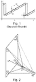
- the frequency deviation per unit of time is the slope of the frequency modulation, as in 1 shown.
- the signal shown in solid lines is a transmit/reference signal and the one shown in dashed lines is a reflected signal.
- the FMCW measurement is only an exemplary embodiment.
- the medical device in one embodiment has at least three receivers sensitive to radar signals (or electromagnetic signals of specific wavelengths) (to determine the transmitter positions in space) and/or at least one transmitter for one electromagnetic signal.
- the pointing stick has at least one transmitter and means for determining the position of the pointing axis in relation to the transmitter. In one embodiment, this means is at least one further second transmitter spatially remote from the first transmitter.
- the pointing stick also includes a receiver. In all embodiments, the pointing stick includes a control device and a power source.
- the transmitter also includes input means for inputting information, analogously to the embodiments with a laser emitter described above.
- the embodiments of the invention based on the evaluation of electromagnetic radiation are preferably based on the determination of the position of the axis of the pointing stick in relation to the device to be operated and, derived from this, the determination of the position of the component of the medical device aimed at by the operator, which is indicated by the projection of the axis determined in this way can be determined on the device surface. This is in 2 clarified.
- the medical device has four receivers (E1-E4).
- a transmitter on the medical device is not shown here.
- the pointing stick has two transmitters S1 and S2, which are arranged on the longitudinal axis of the stick.
- the distance of the transmitters S1 and S2 to all receivers can be determined (indicated by the solid and broken lines from the receivers to the transmitters) and thus the position of the pointer to the medical-technical device by purely geometric calculations in the medical-technical device Device. In this way, the projection of the longitudinal axis onto the device surface (arrow to A) can also be determined.
- the position results from the example 2 from the fact that the distances of the transmitters S1 and S2 to the receivers E1-E4 can be determined and thus result in geometrically unambiguous pyramids whose bases are formed by the rectangle at the corners of which the receivers E1-E4 are located and their respective tips by the transmitters S1 and S2 are formed.
- the location of the peaks is defined by the distances to the individual receivers.
- the length of the pyramid edges corresponds exactly to the respective determined distance.
- the coordinates of the transmitters S1 and S2 can be determined in a reference space. With these coordinates, a vector can be determined on which the transmitters S1 and S2 lie. By mathematically determining the point of intersection of this connection vector with the plane in the reference space on which the receivers E1-E4 lie, the Point of impact A are determined. In 2 four recipients are shown. At least three receivers are required to determine the point of impact.
- This procedure includes the following steps: At time tS, the transmitting device sends an (arbitrary) electromagnetic trigger signal.
- the point in time tS is linked to the signal shown in solid lines.
- the signal shown as a solid line is only available as a reference signal curve in the medical device and is not sent.
- the signal shown in dashed lines is compared with this stored reference signal, e.g. the difference frequency is determined, from which the distance between transmitter and receiver can be derived.
- the trigger signal can be sent periodically to enable permanent position determination.
- the receiving device of the pointing stick receives the trigger signal and immediately initiates the transmission of the characteristic signal shown in dashed lines, which is detected at the time tE on one of the receivers of the medical device.
- the distance between the transmitter and the respective receiver can be determined accordingly by the comparison described above.
- the triggering process is triggered by the pointer, for example by a movement detector in the pointer recognizing a movement, sending out an activation signal via a (any) transmitter, which is received by the medical device, whereupon this sends out the trigger signal in the manner described above .
- a movement detector in the pointer recognizing a movement, sending out an activation signal via a (any) transmitter, which is received by the medical device, whereupon this sends out the trigger signal in the manner described above .
- the transmitter and receiver are arranged at the same point on the medical device.
- a single transmitter can be used on the medical device, which is advantageously at the same distance from all receivers on the medical device.
- the distances to transmitter 1 and transmitter 2 can be determined one after the other in terms of the process, or simultaneously if non-overlapping frequency ranges are used.
- the duration of a measurement ie approximately the modulation period T, is dimensioned so short here that movements of the pointer stick in between are irrelevant. It is typical of the FMCW measurement that the modulation period T is much larger than the propagation time of the signal, due to the propagation speed (speed of light), the short distance (a few meters maximum) and the frequency range (several GHz; e.g. 85-100GHz) However, this results in such small values that it is possible to determine the distance within a very short time period (e.g. ⁇ 1 millisecond).
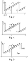
- the transmitted signal can also be used to transmit additional information between the pointing stick and the medical device. This can be modulated, modified or supplemented as desired. Provision can thus be made for the signal from the pointing stick to be characteristically interrupted, thus identifying the pointing stick. In order to determine the distance, it is not necessary for the transmitted signal to contain all frequencies, as in 4 clarified.
- the signal of the stylus shown as a dashed line includes a few gaps at the beginning, during which the signal is interrupted, but the determination of the time offset via the frequency difference of the two signal curves takes place at a later point in time.
- the gaps in the return signal can encode information about the user or the stylus, for example. It is also possible to append information to a modulation period, as shown in figure 5 is shown.
- the data can be modulated onto the carrier signal in any way, for example as a frequency or amplitude or in an FSK method.
- the base frequency is also arbitrary. In the example above, this is within the spectrum of radar frequencies, which means that the same transmitter device can be used for distance determination and data transmission. It is also conceivable that the pointing stick has an additional transmitter that is only set up for data transmission.
- the transmission frequency can be selected in such a way that it does not overlap with the transmitted radar waves. Thus, the data transmission can also take place at the same time as the distance measurement.
- the pointing stick can be equipped with a button and authentication means in an analogous manner.
- the data is transmitted via the transmitter/receiver means of the pointing stick and the medical device, which are sensitive to electromagnetic radiation and are not optical sensors.
- the stylus comprises a single transmitter and additional sensors for determining the inclination of the stylus in space and the angle that the axis of the stylus makes with the earth's magnetic field.
- the person skilled in the art knows high-precision sensors for both sizes, which are also available in designs that are small enough to be able to be integrated in a pointer stick according to the present invention.
- the integrated 360° angle sensor TLE5012B from Infineon and the inclination sensor STMicroelectronics IIS2ICLX should be mentioned here as examples.
- the medical device also knows the location and position in relation to the spatial axes (which can be done with the help of equivalent sensors), the point of impact of the projection of the pointer axis can also be clearly determined by transmitting this information, as in 6 is clarified.
- the angle and/or inclination sensors integrated in the stylus allow the angles ⁇ and ⁇ to be clearly determined in relation to the reference axes x, y and z. If this information is transmitted to the medical device and the relative position of the device surface to the same reference axes is known, a correspondingly programmed control unit can calculate the impact point, taking into account the likewise determined position of the transmitter S1, for example analogously to the method described above.
- a dynamic calculation of the point of impact is at least advantageous. This can be achieved by modeling the device geometry, especially in relation to the receiver, and linking it to the calculation of the beam geometry.
- the modeled device geometry additionally allows the definition of active interaction points/areas corresponding to device elements that can be selected and manipulated. Depending on the user and the current device operating status, the active elements can be changed, enabling context-adaptive control.
- the receiver devices are arranged directly on the medical device. However, this is not absolutely necessary; it is only important that the receiver devices are assigned to the medical device or the received signals can be assigned to a medical device. For example, it is conceivable not to attach the receiver devices as an integral part of a device to be operated, but rather within a room or an area in which several devices can be located.
- receivers can be installed in the corners of the room, which determine the position and the pointing axis of the pointing stick in the above-mentioned manner. If the spatial geometry, dimensions, position and orientation of the devices are known, it can be determined which device and which component is to be targeted and control commands can be issued to them via a central controller. For this purpose, these are networked in terms of data technology.
- the stylus can be assigned to specific people and/or devices to be operated in the above-mentioned manner in order to enable or restrict operation.
- This embodiment is advantageous in particular for large, stationary industrial systems in which the position and orientation of the devices or components to be operated do not change.
- information about targeted system parts is transmitted to an on-board device (tablet, smartphone).
- tablette can be, for example, operating data, maintenance data or general data be information.
- Such a method is particularly advantageous in large industrial plants in which information about plant components is displayed centrally, but information is to be queried on site during use.
- a smartphone could be used to point to a system component. With the help of appropriate sensors, this can be detected in the above-mentioned manner, and information about the corresponding component can then be sent to the smartphone via a networked central control.
- the frequency ranges of the transmitters S1 and S2 can be selected for each pointer in such a way that they do not overlap with those of other pointers.
- a receiving medical device recognizes the received frequency range and selects a corresponding reference signal accordingly. Provision can be made for the spectrum received in the medical device to be divided into corresponding frequency ranges by signal filters. For example, a device can be operated simultaneously with several pointers.
- Another way to avoid unwanted interference is to time-multiplex the method for multiple styluses. This provides for assigning each pointer a periodic time range in which it can emit signals. This can be realized by a central time signal that is sent out and received by each pointing stick. The stylus can then be configured to be active only on certain time slots when no other stylus is active.
- each device notices whether or not a stylus is targeting one of its components, which may mean that it is targeting another device. Accordingly, it becomes “active" only in the first case. In this way, a large number of different devices can be controlled with a single stylus.
Landscapes
- Engineering & Computer Science (AREA)
- General Engineering & Computer Science (AREA)
- Theoretical Computer Science (AREA)
- Physics & Mathematics (AREA)
- General Physics & Mathematics (AREA)
- Human Computer Interaction (AREA)
- Health & Medical Sciences (AREA)
- Remote Sensing (AREA)
- Radar, Positioning & Navigation (AREA)
- Biomedical Technology (AREA)
- Life Sciences & Earth Sciences (AREA)
- General Health & Medical Sciences (AREA)
- Medical Informatics (AREA)
- Public Health (AREA)
- Computer Networks & Wireless Communication (AREA)
- Business, Economics & Management (AREA)
- Primary Health Care (AREA)
- Epidemiology (AREA)
- General Business, Economics & Management (AREA)
- Veterinary Medicine (AREA)
- Pathology (AREA)
- Biophysics (AREA)
- Heart & Thoracic Surgery (AREA)
- Animal Behavior & Ethology (AREA)
- Molecular Biology (AREA)
- Surgery (AREA)
- Position Input By Displaying (AREA)
- User Interface Of Digital Computer (AREA)
Priority Applications (6)
| Application Number | Priority Date | Filing Date | Title |
|---|---|---|---|
| EP21167557.4A EP4071586A1 (fr) | 2021-04-09 | 2021-04-09 | Commande sans contact des appareils médicaux |
| US17/677,069 US11693489B2 (en) | 2021-04-09 | 2022-02-22 | Contactless operation of medical devices using a pointing apparatus |
| CN202280027171.6A CN117120966A (zh) | 2021-04-09 | 2022-04-08 | 医疗设备的非接触式操作 |
| EP22721386.5A EP4320505A2 (fr) | 2021-04-09 | 2022-04-08 | Fonctionnement sans contact de dispositifs médicaux |
| PCT/EP2022/059474 WO2022214673A2 (fr) | 2021-04-09 | 2022-04-08 | Fonctionnement sans contact de dispositifs médicaux |
| US18/198,737 US12039112B2 (en) | 2021-04-09 | 2023-05-17 | Contactless operation of devices using a pointing apparatus |
Applications Claiming Priority (1)
| Application Number | Priority Date | Filing Date | Title |
|---|---|---|---|
| EP21167557.4A EP4071586A1 (fr) | 2021-04-09 | 2021-04-09 | Commande sans contact des appareils médicaux |
Publications (1)
| Publication Number | Publication Date |
|---|---|
| EP4071586A1 true EP4071586A1 (fr) | 2022-10-12 |
Family
ID=75690080
Family Applications (2)
| Application Number | Title | Priority Date | Filing Date |
|---|---|---|---|
| EP21167557.4A Withdrawn EP4071586A1 (fr) | 2021-04-09 | 2021-04-09 | Commande sans contact des appareils médicaux |
| EP22721386.5A Pending EP4320505A2 (fr) | 2021-04-09 | 2022-04-08 | Fonctionnement sans contact de dispositifs médicaux |
Family Applications After (1)
| Application Number | Title | Priority Date | Filing Date |
|---|---|---|---|
| EP22721386.5A Pending EP4320505A2 (fr) | 2021-04-09 | 2022-04-08 | Fonctionnement sans contact de dispositifs médicaux |
Country Status (4)
| Country | Link |
|---|---|
| US (2) | US11693489B2 (fr) |
| EP (2) | EP4071586A1 (fr) |
| CN (1) | CN117120966A (fr) |
| WO (1) | WO2022214673A2 (fr) |
Citations (8)
| Publication number | Priority date | Publication date | Assignee | Title |
|---|---|---|---|---|
| WO1999008128A1 (fr) | 1997-08-11 | 1999-02-18 | Mikrowellen-Technologie Und Sensoren Gmbh | Dispositif permettant de mesurer la distance d'un radar |
| WO2007009833A1 (fr) | 2005-07-18 | 2007-01-25 | Robert Bosch Gmbh | Procede et circuit permettant de determiner precisement une distance |
| WO2008042220A2 (fr) * | 2006-09-29 | 2008-04-10 | Nellcor Puritan Bennett Llc | Interface utilisateur et identification intégrés et un dispositif médical, systèmes et procédés |
| US20120326979A1 (en) * | 2011-06-21 | 2012-12-27 | International Business Machines Corporation | Remote controlling of mouse cursor functions of a computer device |
| WO2016204641A1 (fr) | 2015-06-17 | 2016-12-22 | Novelic D.O.O. | Système de capteur à ondes millimétriques pour aide au stationnement |
| WO2018167777A1 (fr) | 2017-03-12 | 2018-09-20 | Neteera Technologies Ltd. | Procédé et dispositif de détection sans contact de signes vitaux et de signaux de diagnostiques par ondes électromagnétiques dans la bande sous-térahertz |
| WO2020127177A1 (fr) | 2018-12-18 | 2020-06-25 | Endress+Hauser SE+Co. KG | Procédé de mesure de distance basée sur une fmcw |
| DE102019002278A1 (de) | 2019-03-29 | 2020-10-01 | OndoSense GmbH | Radareinheit zur Vermessung eines Abstands zu einer reflektierenden Oberfläche |
Family Cites Families (18)
| Publication number | Priority date | Publication date | Assignee | Title |
|---|---|---|---|---|
| US6184831B1 (en) * | 1988-12-02 | 2001-02-06 | The Boeing Company | Method and system for determining location and velocity of electromagnetic emitters using doppler frequency measurements |
| JP4164423B2 (ja) * | 2003-08-29 | 2008-10-15 | キヤノン株式会社 | センシング部とポインティングデバイスとを含み構成される装置 |
| US7525050B1 (en) * | 2004-04-23 | 2009-04-28 | Luidia, Inc. | Interference removal in pointing device locating systems |
| US7548185B2 (en) * | 2005-09-30 | 2009-06-16 | Battelle Memorial Institute | Interlaced linear array sampling technique for electromagnetic wave imaging |
| US8570274B1 (en) * | 2005-11-29 | 2013-10-29 | Navisense | Navigation device providing sensory feedback |
| RU2368941C1 (ru) | 2008-02-22 | 2009-09-27 | Открытое Акционерное Общество "Интеллект Телеком" | Способ определения координат манипулятора типа "мышь" или "электронное перо" и устройство для его осуществления |
| EP2267477A1 (fr) * | 2009-06-17 | 2010-12-29 | Nederlandse Organisatie voor toegepast -natuurwetenschappelijk onderzoek TNO | Procédé de détection d'une distance, système de radar et produit de programme informatique |
| US10222462B2 (en) * | 2013-02-27 | 2019-03-05 | Waymo Llc | Adaptive algorithms for interrogating the viewable scene of an automotive radar |
| CN106164705B (zh) * | 2014-12-19 | 2019-03-08 | 中国科学院电子学研究所 | 采用一发多收雷达探测地外固态星体结构的方法与系统 |
| US10591592B2 (en) * | 2015-06-15 | 2020-03-17 | Humatics Corporation | High-precision time of flight measurement systems |
| US10817065B1 (en) * | 2015-10-06 | 2020-10-27 | Google Llc | Gesture recognition using multiple antenna |
| JP2018013358A (ja) * | 2016-07-19 | 2018-01-25 | ソニーセミコンダクタソリューションズ株式会社 | レーダ装置、信号処理装置、信号処理方法及び移動体 |
| KR102523266B1 (ko) | 2018-01-16 | 2023-04-21 | 삼성전자주식회사 | 디스플레이 장치, 디스플레이 시스템 및 그 제어방법 |
| CN116300091A (zh) | 2018-07-23 | 2023-06-23 | 奇跃公司 | 用于使用位置向量解析半球模糊度的方法和系统 |
| US11471102B2 (en) * | 2019-06-20 | 2022-10-18 | Medici Technologies Llc | Hydration assessment system |
| US20210349177A1 (en) * | 2020-05-08 | 2021-11-11 | 7hugs Labs SAS | Low profile pointing device |
| DE102020114502A1 (de) * | 2020-05-29 | 2021-12-02 | Fresenius Medical Care Deutschland Gmbh | Medizinisches Set zum Überwachen eines Patienten mittels Radarwellen |
| EP4029439B1 (fr) * | 2021-01-11 | 2024-09-04 | Qumea AG | Procédé de surveillance d'un patient couché pour obtenir des informations sur la position du corps du patient |
-
2021
- 2021-04-09 EP EP21167557.4A patent/EP4071586A1/fr not_active Withdrawn
-
2022
- 2022-02-22 US US17/677,069 patent/US11693489B2/en active Active
- 2022-04-08 WO PCT/EP2022/059474 patent/WO2022214673A2/fr not_active Ceased
- 2022-04-08 CN CN202280027171.6A patent/CN117120966A/zh active Pending
- 2022-04-08 EP EP22721386.5A patent/EP4320505A2/fr active Pending
-
2023
- 2023-05-17 US US18/198,737 patent/US12039112B2/en active Active
Patent Citations (8)
| Publication number | Priority date | Publication date | Assignee | Title |
|---|---|---|---|---|
| WO1999008128A1 (fr) | 1997-08-11 | 1999-02-18 | Mikrowellen-Technologie Und Sensoren Gmbh | Dispositif permettant de mesurer la distance d'un radar |
| WO2007009833A1 (fr) | 2005-07-18 | 2007-01-25 | Robert Bosch Gmbh | Procede et circuit permettant de determiner precisement une distance |
| WO2008042220A2 (fr) * | 2006-09-29 | 2008-04-10 | Nellcor Puritan Bennett Llc | Interface utilisateur et identification intégrés et un dispositif médical, systèmes et procédés |
| US20120326979A1 (en) * | 2011-06-21 | 2012-12-27 | International Business Machines Corporation | Remote controlling of mouse cursor functions of a computer device |
| WO2016204641A1 (fr) | 2015-06-17 | 2016-12-22 | Novelic D.O.O. | Système de capteur à ondes millimétriques pour aide au stationnement |
| WO2018167777A1 (fr) | 2017-03-12 | 2018-09-20 | Neteera Technologies Ltd. | Procédé et dispositif de détection sans contact de signes vitaux et de signaux de diagnostiques par ondes électromagnétiques dans la bande sous-térahertz |
| WO2020127177A1 (fr) | 2018-12-18 | 2020-06-25 | Endress+Hauser SE+Co. KG | Procédé de mesure de distance basée sur une fmcw |
| DE102019002278A1 (de) | 2019-03-29 | 2020-10-01 | OndoSense GmbH | Radareinheit zur Vermessung eines Abstands zu einer reflektierenden Oberfläche |
Non-Patent Citations (1)
| Title |
|---|
| DONATO PASQUARIELLO, M. C. J. M. VISSENBERGGALILEO JUNE DESTURA: "Remote-Touch: A Laser Input User-Display Interaction Technology", J. DISPLAY TECHNOL., vol. 4, 2008, pages 39 - 46 |
Also Published As
| Publication number | Publication date |
|---|---|
| US20220326786A1 (en) | 2022-10-13 |
| WO2022214673A2 (fr) | 2022-10-13 |
| US11693489B2 (en) | 2023-07-04 |
| US12039112B2 (en) | 2024-07-16 |
| EP4320505A2 (fr) | 2024-02-14 |
| US20230288995A1 (en) | 2023-09-14 |
| CN117120966A (zh) | 2023-11-24 |
| WO2022214673A3 (fr) | 2022-11-24 |
Similar Documents
| Publication | Publication Date | Title |
|---|---|---|
| EP1302172B1 (fr) | Instrument médical avec une pointe sensible au toucher | |
| EP2227703B1 (fr) | Procédé de capture de mouvements | |
| DE69130282T2 (de) | Positions- und Funktionseingabesystem für Grossoberflächenanzeige | |
| DE112019001902T5 (de) | Messvorrichtung, Verfahren und Programm zum messen biologischer Informationen | |
| EP3305232B1 (fr) | Dispositif de commande et procede de commande pour l'opération d'un dispositif médical | |
| DE102013101158A1 (de) | Medizinische Vorrichtung und Verfahren zum Konfigurieren eines medizinischen Systems | |
| WO2013044893A1 (fr) | Gant de données à rétro-information tactile et procédé | |
| WO2012127017A1 (fr) | Appareil de mesure de distance électro-optique comprenant un déclenchement de mesure par geste fonctionnant sans contact | |
| DE102008044423A1 (de) | Bildgebungsmehrkopfsonde und Bildgebungssystem, das diese verwendet | |
| DE102013226242A1 (de) | Einstellung eines Aufnahmebereichs | |
| DE102015212421B4 (de) | Steuerverfahren und elektronische Vorrichtung | |
| EP2609446A1 (fr) | Détermination de position au moyen d'étiquettes rfid | |
| EP3992925A1 (fr) | Dispositif et procédé d'imagerie optique sans contact d'une zone de surface sélectionnée d'une main | |
| EP3573854B1 (fr) | Procédé de fonctionnement d'un système de commande actionné, système de commande et véhicule avec un système de commande | |
| EP1637985A2 (fr) | Introduction de commandes d'entrée d'appareils | |
| EP4071586A1 (fr) | Commande sans contact des appareils médicaux | |
| EP2602679A1 (fr) | Elément de commande pour un appareil ménager, unité de commande d'un appareil ménager destiné à la réception d'un tel élément de commande et appareil ménager doté d'une telle unité de commande et d'un tel élément de commande | |
| WO2000008593A2 (fr) | Souris mixte | |
| EP3640773A1 (fr) | Crayon de saisie à télémètre | |
| DE102005013063A1 (de) | Verfahren und Anordnung zur drahtlosen Steuerung eines Gerätes, insbesondere in der Medizin | |
| DE102017111367A1 (de) | Abstandsmesssystem, -verfahren und diese verwendendes Robotersystem | |
| EP4208877B1 (fr) | Système et procédé de surveillance d'au moins un dispositif médical | |
| DE19634781C1 (de) | Verfahren zur berührungslosen Erkennung von Verschwenkungswinkeln | |
| DE102013007820A1 (de) | Verfahren zur Eingabe von Daten und eine dafür geeignete Vorrichtung | |
| DE102006044620A1 (de) | Positionslandmarkingverfahren unter Verwendung eines berührungsempfindlichen Arrays |
Legal Events
| Date | Code | Title | Description |
|---|---|---|---|
| PUAI | Public reference made under article 153(3) epc to a published international application that has entered the european phase |
Free format text: ORIGINAL CODE: 0009012 |
|
| STAA | Information on the status of an ep patent application or granted ep patent |
Free format text: STATUS: REQUEST FOR EXAMINATION WAS MADE |
|
| 17P | Request for examination filed |
Effective date: 20210409 |
|
| AK | Designated contracting states |
Kind code of ref document: A1 Designated state(s): AL AT BE BG CH CY CZ DE DK EE ES FI FR GB GR HR HU IE IS IT LI LT LU LV MC MK MT NL NO PL PT RO RS SE SI SK SM TR |
|
| STAA | Information on the status of an ep patent application or granted ep patent |
Free format text: STATUS: THE APPLICATION IS DEEMED TO BE WITHDRAWN |
|
| 18D | Application deemed to be withdrawn |
Effective date: 20230413 |