EP4071954A1 - Blitzschutzvorrichtung und fotovoltaisches stromerzeugungssystem - Google Patents
Blitzschutzvorrichtung und fotovoltaisches stromerzeugungssystem Download PDFInfo
- Publication number
- EP4071954A1 EP4071954A1 EP22167255.3A EP22167255A EP4071954A1 EP 4071954 A1 EP4071954 A1 EP 4071954A1 EP 22167255 A EP22167255 A EP 22167255A EP 4071954 A1 EP4071954 A1 EP 4071954A1
- Authority
- EP
- European Patent Office
- Prior art keywords
- lightning protection
- protection unit
- terminal
- lightning
- protection apparatus
- Prior art date
- Legal status (The legal status is an assumption and is not a legal conclusion. Google has not performed a legal analysis and makes no representation as to the accuracy of the status listed.)
- Granted
Links
Images




Classifications
-
- H—ELECTRICITY
- H02—GENERATION; CONVERSION OR DISTRIBUTION OF ELECTRIC POWER
- H02H—EMERGENCY PROTECTIVE CIRCUIT ARRANGEMENTS
- H02H9/00—Emergency protective circuit arrangements for limiting excess current or voltage without disconnection
- H02H9/04—Emergency protective circuit arrangements for limiting excess current or voltage without disconnection responsive to excess voltage
- H02H9/06—Emergency protective circuit arrangements for limiting excess current or voltage without disconnection responsive to excess voltage using spark-gap arresters
-
- H—ELECTRICITY
- H02—GENERATION; CONVERSION OR DISTRIBUTION OF ELECTRIC POWER
- H02H—EMERGENCY PROTECTIVE CIRCUIT ARRANGEMENTS
- H02H9/00—Emergency protective circuit arrangements for limiting excess current or voltage without disconnection
- H02H9/04—Emergency protective circuit arrangements for limiting excess current or voltage without disconnection responsive to excess voltage
- H02H9/045—Emergency protective circuit arrangements for limiting excess current or voltage without disconnection responsive to excess voltage adapted to a particular application and not provided for elsewhere
-
- H—ELECTRICITY
- H01—ELECTRIC ELEMENTS
- H01C—RESISTORS
- H01C7/00—Non-adjustable resistors formed as one or more layers or coatings; Non-adjustable resistors made from powdered conducting material or powdered semi-conducting material with or without insulating material
- H01C7/10—Non-adjustable resistors formed as one or more layers or coatings; Non-adjustable resistors made from powdered conducting material or powdered semi-conducting material with or without insulating material voltage responsive, i.e. varistors
- H01C7/12—Overvoltage protection resistors; Arresters
-
- H—ELECTRICITY
- H02—GENERATION; CONVERSION OR DISTRIBUTION OF ELECTRIC POWER
- H02H—EMERGENCY PROTECTIVE CIRCUIT ARRANGEMENTS
- H02H9/00—Emergency protective circuit arrangements for limiting excess current or voltage without disconnection
- H02H9/04—Emergency protective circuit arrangements for limiting excess current or voltage without disconnection responsive to excess voltage
-
- H—ELECTRICITY
- H02—GENERATION; CONVERSION OR DISTRIBUTION OF ELECTRIC POWER
- H02H—EMERGENCY PROTECTIVE CIRCUIT ARRANGEMENTS
- H02H9/00—Emergency protective circuit arrangements for limiting excess current or voltage without disconnection
- H02H9/04—Emergency protective circuit arrangements for limiting excess current or voltage without disconnection responsive to excess voltage
- H02H9/041—Emergency protective circuit arrangements for limiting excess current or voltage without disconnection responsive to excess voltage using a short-circuiting device
-
- H—ELECTRICITY
- H02—GENERATION; CONVERSION OR DISTRIBUTION OF ELECTRIC POWER
- H02H—EMERGENCY PROTECTIVE CIRCUIT ARRANGEMENTS
- H02H9/00—Emergency protective circuit arrangements for limiting excess current or voltage without disconnection
- H02H9/04—Emergency protective circuit arrangements for limiting excess current or voltage without disconnection responsive to excess voltage
- H02H9/042—Emergency protective circuit arrangements for limiting excess current or voltage without disconnection responsive to excess voltage comprising means to limit the absorbed power or indicate damaged over-voltage protection device
Definitions
- This application relates to the field of power electronics technologies, and in particular, to a lightning protection apparatus and a photovoltaic power generation system.
- a photovoltaic power generation technology is increasingly widely applied.
- a lightning protection apparatus is disposed in the photovoltaic power generation system.
- one or more varistors are connected between an electrical energy transmission cable and an earth wire of the photovoltaic power generation system.
- the varistor clamps the voltage on the cable and transmits lightning energy to the earth wire through the varistor.
- a spark-over voltage value of the varistor is small.
- a varistor with higher costs and a higher spark-over voltage value needs to be used.
- the photovoltaic power generation system is short-circuited, a voltage between two terminals of a varistor connected to a failure-free cable increases. In a serious case, the varistor is broken down, and secondary damage is caused to the photovoltaic power generation system.
- This application provides a lightning protection apparatus and a photovoltaic power generation system, to reduce lightning protection costs of the lightning protection apparatus and ensure safe operation of the system.
- an embodiment of this application provides a lightning arrester.
- the lightning arrester may be used in a photovoltaic power generation system, to perform lightning protection on the photovoltaic power generation system.
- the lightning arrester may include first lightning protection units in a one-to-one correspondence with phase lines at a to-be-protected location in the photovoltaic power generation system and a second lightning protection unit connected in series to the first lightning protection units.
- a first terminal of each first lightning protection unit is connected to a corresponding to-be-protected phase line, and a second terminal of each first lightning protection unit is connected to a first terminal of the second lightning protection unit.
- a second terminal of the second lightning protection unit is connected to an earth wire.
- the second lightning protection unit includes at least one gas discharge tube.
- the second lightning protection unit can use a gas discharge tube with lower lightning protection costs and a higher spark-over voltage value for lightning protection, to improve a spark-over voltage level of the entire lightning protection apparatus.
- the gas discharge tube can effectively prevent another failure-free phase line from having a short-circuit failure caused by high-voltage breakdown, thereby ensuring safe operation of the photovoltaic power generation system.
- each first lightning protection unit includes a first varistor.
- the first varistor and the second lightning protection unit can be used to perform voltage division on a voltage on the phase line, and the first varistor is connected in series to the second lightning protection unit to constitute a transmission path for transmitting lightning energy to the earth wire.
- each first lightning protection unit includes a first branch including a plurality of second varistors connected in series.
- a first terminal of the first branch constitutes the first terminal of the first lightning protection unit, and a second terminal of the first branch constitutes the second terminal of the first lightning protection unit.
- a spark-over voltage value of the first lightning protection unit can be increased by connecting a plurality of varistors in series for voltage division, to meet the lightning protection requirement of the photovoltaic power generation system.
- each first lightning protection unit includes a first gas discharge tube.
- a first gas discharge tube with a higher spark-over voltage value can be used to further improve the spark-over voltage level of the entire lightning protection apparatus.
- each first lightning protection unit includes a second branch including a plurality of second gas discharge tubes connected in series.
- a first terminal of the second branch constitutes the first terminal of the first lightning protection unit, and a second terminal of the second branch constitutes the second terminal of the first lightning protection unit.
- a spark-over voltage value of the first lightning protection unit can be increased by connecting a plurality of gas discharge tubes in series for voltage division, to meet the lightning protection requirement of the photovoltaic power generation system.
- the second lightning protection unit includes a third gas discharge tube.
- a gas discharge tube with a higher spark-over voltage value and a higher resistance value is connected between the earth wire and the first lightning protection units. This is applicable to a photovoltaic power generation system with a higher lightning protection level.
- a spark-over voltage value of a device in the first lightning protection unit can be effectively reduced, failures of the device in the first lightning protection unit can be reduced, and safe operation of the lightning protection apparatus can be ensured.
- the second lightning protection unit includes a third branch including a plurality of fourth gas discharge tubes connected in series.
- a first terminal of the third branch constitutes the first terminal of the second lightning protection unit, and a second terminal of the third branch constitutes the second terminal of the second lightning protection unit.
- a spark-over voltage value of the first lightning protection unit can be increased by connecting a plurality of gas discharge tubes in series for voltage division, to meet the lightning protection requirement of the photovoltaic power generation system.
- the second lightning protection unit further includes a third varistor connected between the third gas discharge tube and the earth wire.
- a gas discharge tube may cooperate with a varistor, so that while the spark-over voltage level of the lightning protection apparatus is improved by the gas discharge tube, operation sensitivity of the lightning protection apparatus is improved by using the varistor, to meet a lightning protection requirement of the photovoltaic power generation system.
- the lightning protection apparatus further includes a third lightning protection unit connected in parallel to the second lightning protection unit, and the third lightning protection unit includes at least one gas discharge tube.
- the photovoltaic power generation system mostly performs a lightning protection test by using a direct current cable for transmitting a direct current.
- the lightning protection apparatus connected to the direct current cable undergoes a plurality of lightning stroke tests.
- the third lightning protection unit connected in parallel to the second lightning protection unit can be added.
- the second lightning protection unit fails because the phase line connected to the lightning protection apparatus undergoes a lightning stroke, the third lightning protection unit can be used to transmit lightning energy, thereby effectively prolonging the service life of the lightning protection apparatus.
- the second lightning protection unit further includes a first resistor connected in parallel to the third gas discharge tube.
- a resistance value of a gas discharge tube is far greater than that of a varistor.
- a resistor connected in parallel to the gas discharge tube can be disposed for voltage division processing.
- an embodiment of this application provides a photovoltaic power generation system.
- the photovoltaic power generation system may include a plurality of photovoltaic components, a direct current to direct current DC/DC converter, a direct current to alternating current DC/AC converter, and the first lightning protection apparatus provided in the first aspect and any possible design of the first aspect in embodiments of this application.
- Output terminals of the plurality of photovoltaic components are connected to an input terminal of the DC/DC converter; an output terminal of the DC/DC converter is connected to an input terminal of the DC/AC converter; and an output terminal of the DC/AC converter is connected to the first lightning protection apparatus.
- a lightning protection apparatus with lower costs can be used to perform lightning protection on the DC/AC converter.
- the system further includes second lightning protection apparatuses in a one-to-one correspondence with the plurality of photovoltaic components.
- Each second lightning protection apparatus is connected to an output terminal of a corresponding photovoltaic component.
- the system further includes a third lightning protection apparatus connected to the output terminal of the DC/DC converter.
- a specific operation method in a method embodiment may also be applied to an apparatus embodiment or a system embodiment.
- at least one means one or more
- a plurality of' means two or more.
- a plurality of may also be understood as “at least two” in embodiments of the present invention.
- the term “and/or” describes an association relationship for describing associated objects and represents that three relationships may exist. For example, A and/or B may represent the following three cases: Only A exists, both A and B exist, and only B exists. In addition, the character "/" usually indicates an "or” relationship between the associated objects unless otherwise specified.
- connection in embodiments of this application is an electric connection, and the connection between two electrical elements may be a direct or indirect connection between the two electrical elements.
- a connection between A and B may represent that A and B are directly connected to each other, or A and B are indirectly connected to each other by using one or more other electrical elements.
- the connection between A and B may also represent that A is directly connected to C, C is directly connected to B, and A and B are connected to each other through C.
- FIG. 1 is a possible schematic diagram of a structure of the photovoltaic power generation system.
- the photovoltaic power generation system includes a plurality of photovoltaic components, a direct current (direct current, DC) to direct current converter (DC/DC converter), and a direct current to an alternating current (alternating current, AC) converter (DC/AC converter).
- Output terminals of the plurality of photovoltaic components are all connected to an input terminal of the DC/DC converter, an output terminal of the DC/DC converter is connected to an input terminal of the DC/AC converter, and an output terminal of the DC/AC converter is connected to a grid.
- the lightning arrester may be disposed on a direct current cable for transmitting a direct current and an alternating current cable used for transmitting an alternating current that are in the photovoltaic power generation device, to perform lightning protection on the direct current cable and the alternating current cable, and ensure operation safety of the photovoltaic power generation system.
- FIG. 2 shows a schematic diagram of a structure of a lightning protection apparatus connected to the output terminals of the DC/AC converter.
- three phase lines L1, L2, and L3 at the output terminals of the DC/AC converter each are connected to one varistor, and three varistors connected to the three phase lines are all connected to an earth wire by using one varistor.
- a voltage of each phase line is divided by the two varistors connected between the phase line and the earth wire.
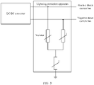
- FIG. 3 shows a schematic diagram of a structure of a lightning protection apparatus connected to the output terminals of the DC/DC converter.
- two phase lines namely, a positive direct current bus and a negative direct current bus
- varistors connected to the positive direct current bus and the negative direct current bus are all connected to the earth wire by using one varistor.
- a voltage of each phase line is divided by the two varistors connected between the phase line and the earth wire.
- FIG. 2 and FIG. 3 separately show connection manners of a lightning protection apparatus on a direct current cable and an alternating current cable.
- an existing lightning protection apparatus mostly uses varistors to perform lightning protection.
- a specific specification of the varistor needs to be set based on an operating voltage of a photovoltaic power generation system and a lightning protection requirement of the system. For a photovoltaic power generation system with a higher operating voltage, a higher withstand voltage level of a varistor indicates higher costs of the varistor.
- embodiments of this application provide a lightning protection apparatus and a photovoltaic power generation system, which may be applied to the photovoltaic power generation system shown in FIG. 1 , to reduce lightning protection costs of the photovoltaic power generation system and ensure normal running of the photovoltaic power generation system.
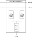
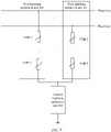
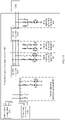
- FIG. 4 is a schematic diagram of a structure of a lightning protection apparatus according to an embodiment of this application.
- the lightning protection apparatus 400 mainly includes first lightning protection units 401 in a one-to-one correspondence with phase lines at a to-be-protected location in a photovoltaic power generation system and a second lightning protection unit 402 connected in series to the first lightning protection units 401.
- a first terminal of each first lightning protection unit 401 is connected to a corresponding phase line at the to-be-protected location, and a second terminal of each first lightning protection unit 401 is connected to a first terminal of the second lightning protection unit 402.
- a second terminal of the second lightning protection unit 402 is connected to an earth wire.
- the second lightning protection unit 402 includes at least one gas discharge tube.
- the lightning protection apparatus 400 When the lightning protection apparatus 400 is configured to perform lightning protection on the photovoltaic power generation system, if the photovoltaic power generation system undergoes a lightning stroke, lightning energy exists on the phase line at the to-be-protected location.
- the lightning energy makes values of a voltage and a current on the phase line increase and exceed a preset threshold.
- the first lightning protection unit 401 and the second lightning protection unit 402 operate to clamp the voltage on the phase line, and constitute an electrical energy transmission path between the phase line and the earth wire.
- An excessive current on the phase line is transmitted to the earth wire through the electrical energy transmission path, so that the lightning energy is released, thereby effectively preventing the lightning energy from damaging a device in the system, and ensuring safe operation of the photovoltaic power generation system.
- the lightning protection apparatus 400 provided in this embodiment of this application has an advantage of low lightning protection costs. Specifically, the first lightning protection unit 401 and the second lightning protection unit 402 are connected in series, to perform voltage division processing on the voltage on the phase line. Because the second lightning protection unit 402 uses a gas discharge tube with lower costs, a higher spark-over voltage value, and a higher impedance value, the second lightning protection unit 402 is not damaged when bearing a high voltage. This improves a spark-over voltage level of the lightning protection apparatus 400 without increasing costs of the lightning protection apparatus 400, and is applicable to a photovoltaic power generation system with a higher operating voltage.
- the second lightning protection unit 402 uses the gas discharge tube with a higher impedance value, when a voltage between a failure-free phase line and the earth wire increases because any phase line connected to the lightning protection apparatus 400 has a short-circuit failure, a high impedance of the gas discharge tube may effectively prevent the failure-free phase line from being short-circuited due to high-voltage breakdown, prevent the photovoltaic power generation system from secondary damage, and ensure safe operation of the photovoltaic power generation system.
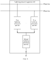
- FIG. 5 a lightning energy transmission equivalent circuit of the lightning protection apparatus 400 may be shown in FIG. 5 .
- an endpoint that is of each first lightning protection unit 401 and that is connected to the phase line is used as an input terminal of the lightning protection apparatus 400
- an endpoint that is of the second lightning protection unit 402 and that is connected to the earth wire is used as an output of the lightning protection apparatus 400, and energy is transmitted from top to bottom.
- the to-be-protected location of the photovoltaic power generation system may be an output terminal of a photovoltaic component, an output terminal of a DC/DC converter, or an output terminal of a DC/AC converter.
- the lightning arrester further includes a third lightning protection unit connected in parallel to the second lightning protection unit, and the third lightning protection unit includes at least one gas discharge tube.
- the photovoltaic power generation system converts a generated direct current into an alternating current for outputting, when a direct current cable undergoes a lightning stroke, a lightning protection apparatus connected to the direct current cable operates first, and releases a large part of lightning energy to the earth wire. In this case, only a small part of lightning energy reaches an alternating current cable.
- the lightning protection apparatus connected to the direct current cable releases the large part of lightning energy, and a lightning protection apparatus connected to the alternating current cable releases only the small part of lightning energy.
- the third lightning protection unit configured to be connected in parallel to the second lightning protection unit 402 is added to the lightning protection apparatus 400 connected to the direct current cable.
- the third lightning protection unit includes at least one gas discharge tube.
- a structure of the third lightning protection unit is the same as a structure of the second lightning protection unit 402.
- the lightning protection apparatus 400 may be fastened onto the photovoltaic power generation system, and the lightning protection apparatus 400 may be connected to the phase line at the to-be-protected location through a fixed interface on the photovoltaic power generation system.
- the lightning protection apparatus 400 may be alternatively disposed in a flexible and detachable form.
- a pluggable interface is disposed on the photovoltaic power generation system, so that the phase line at the to-be-protected location is connected to the lightning protection apparatus 400.
- the lightning protection apparatus 400 may be considered as an apparatus independent of the photovoltaic power generation system.
- the following describes specific structures of the first lightning protection unit 401 and the second lightning protection unit 402 in the lightning protection apparatus 400.
- each first lightning protection unit 401 is connected to the corresponding phase line at the to-be-protected location
- the second terminal of each first lightning protection unit 401 is connected to the first terminal of the second lightning protection unit 402
- each first lightning protection unit 401 may be configured to clamp a voltage on the connected phase line when a voltage between the two terminals of the first lightning protection unit 401 is greater than an operating voltage of a device in the first lightning protection unit 401.
- a function of disposing the plurality of first lightning protection units 401 is as follows: When the photovoltaic power generation system undergoes a lightning stroke, lightning energy may exist on a plurality of phase lines at the to-be-protected location.
- the first lightning protection units 401 connected to each phase line and the second lightning protection unit 402 may be configured to constitute a lightning energy transmission path between each phase line and the earth wire, to transmit the lightning energy to the earth wire through the lightning energy transmission path, thereby implementing lightning protection of each phase line at the to-be-protected location.
- the lightning protection apparatus 400 implements a Y-type connection by using the plurality of first lightning protection units 401.
- the first lightning protection unit 401 may include a first gas discharge tube connected to a corresponding phase line at the to-be-protected location.
- the first lightning protection unit 401 may include a second branch including a plurality of second gas discharge tubes connected in series.
- a first terminal of the second branch constitutes the first terminal of the first lightning protection unit 401, and a second terminal of the second branch constitutes the second terminal of the first lightning protection unit 401.
- the second lightning protection unit 402 may effectively improve the spark-over voltage level of the lightning protection apparatus 400 by using a gas discharge tube, and the first lightning protection unit 401 may further improve the spark-over voltage level of the lightning protection apparatus 400 by using a gas discharge tube.
- the first lightning protection unit 401 may include a first varistor connected to a corresponding phase line at the to-be-protected location.
- the first lightning protection unit 401 may include a first branch including a plurality of second varistors connected in series.
- a first terminal of the first branch constitutes the first terminal of the first lightning protection unit 401, and a second terminal of the first branch constitutes the second terminal of the first lightning protection unit 401.
- the second lightning protection unit 402 may effectively improve the spark-over voltage level of the lightning protection apparatus by using a gas discharge tube.
- operation sensitivity of the gas discharge tube is low, and when lightning energy exists on a connected phase line, the gas discharge tube cannot be timely started to operate to perform lightning protection on the to-be-protected location.
- the first lightning protection unit 401 may be used together with the gas discharge tube in the second lightning protection unit 402 by using a varistor, to improve sensitivity of the lightning protection apparatus 400 while reducing lightning protection costs of the lightning protection apparatus 400.
- the following provides specific examples of two structures of the first lightning protection unit 401.
- FIG. 6 is a schematic diagram of a structure of the first lightning protection unit 401 according to an embodiment of this application.
- a GDT 1 may be considered as a first gas discharge tube
- a port A may be considered as an input terminal of the first lightning protection unit 401
- a port B may be considered as an output terminal of the first lightning protection unit 401.
- a connection relationship of devices in the first lightning protection unit 401 shown in FIG. 6 may be that a first terminal of the GDT 1 is connected to the phase line corresponding to the first lightning protection unit 401, and a second terminal of the GDT 1 is connected to the first terminal of the second lightning protection unit 402.
- the GDT 1 and the second lightning protection unit 402 perform voltage division on the connected phase line.
- the lightning energy causes both a voltage and a current on the phase line to be increased.
- the GDT 1 clamps the voltage on the connected phase line, and transmits an excessive current on the phase line to the earth wire through the second lightning protection unit 402.
- the excessive current is a current part on the phase line that exceeds an operating current.
- the first lightning protection unit may use a plurality of second gas discharge tubes GDT 2 connected in series, to meet the spark-over voltage requirement at the to-be-protected location.
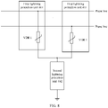
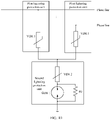
- FIG. 8 is a schematic diagram of another structure of the first lightning protection unit 401 according to an embodiment of this application.
- a VDR 1 may be considered as a first varistor
- a port A may be considered as an input terminal of the first lightning protection unit 401
- a port B may be considered as an output terminal of the first lightning protection unit 401.
- a connection relationship of devices in the first lightning protection unit 401 shown in FIG. 8 may be that a first terminal of the VDR 1 is connected to the phase line corresponding to the first lightning protection unit, and a second terminal of the VDR 1 is connected to the first terminal of the second lightning protection unit 402.
- the VDR 1 and the second lightning protection unit perform voltage division on the connected phase line.
- both a voltage and a current on the phase line increase.
- the VDR 1 clamps the voltage on the connected phase line, and transmits an excessive current on the phase line to the earth wire through the second lightning protection unit.
- the excessive current is a current part on the phase line that exceeds an operating current.
- the first lightning protection unit may use a plurality of second varistors VDR 2 connected in series, to meet the spark-over voltage requirement at the to-be-protected location.
- the first lightning protection unit 401 may alternatively use another structure.
- the first lightning protection unit 401 may include a transient suppression diode, and the transient suppression diode clamps the voltage on the connected phase line.
- the first terminal of the second lightning protection unit 402 is separately connected to second terminals of the plurality of first lightning protection units 401, the second terminal of the second lightning protection unit 402 is connected to the earth wire, and the second lightning protection unit 402 is configured to constitute an electrical energy transmission path between a phase line and the earth wire with the first lightning protection unit 401, and transmit lightning energy on the phase line connected to the first lightning protection unit 401 to the earth wire through the electrical energy transmission path.
- the second lightning protection unit 402 includes a second gas discharge tube connected between the first lightning protection unit 401 and the earth wire.
- the second lightning protection unit may include a third branch including a plurality of second gas discharge tubes connected in series.
- a first terminal of the third branch constitutes the first terminal of the second lightning protection unit 402, and a second terminal of the third branch constitutes the second terminal of the second lightning protection unit 402.
- the second lightning protection unit 402 may use a single gas discharge tube or a plurality of gas discharge tubes connected in series. Because the gas discharge tube has a high impedance and a high spark-over voltage value, when a voltage and a current on the phase line increase because lightning energy occurs on the phase line, a large part of the voltage on the phase line is borne by a device in the second lightning protection unit 402, to reduce a voltage between two terminals of a device in the first lightning protection unit 401. This can prevent the first lightning protection unit 401 from being damaged while improving a spark-over voltage level of the lightning protection apparatus 400.
- the second lightning protection unit 402 further includes a third varistor connected between the third gas discharge tube and the earth wire.
- an impedance value of a gas discharge tube in the second lightning protection unit 402 is greater than that of a varistor.
- a first resistor may be connected in parallel to the two terminals of the gas discharge tube, to reduce a value of a voltage borne by the two terminals of the gas discharge tube.
- the second lightning protection unit 402 may alternatively use another structure.
- the first lightning protection unit 401 may include a gas discharge tube and a transient suppression diode, and the transient suppression diode and the gas discharge tube are connected in series to clamp the voltage on the phase line.
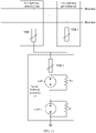
- FIG. 10 a lightning protection apparatus provided in embodiments of this application may be shown in FIG. 10 .
- a first lightning protection unit includes a first varistor VDR 1.
- a first terminal of the VDR 1 is connected to a corresponding phase line at a to-be-protected location, and a second terminal of the VDR 1 is connected to a first terminal of a second lightning protection unit.
- the second lightning protection unit includes a second varistor VDR 2, a first gas discharge tube GDT 1, and a first resistor R1.
- a first terminal of the VDR 2 is connected to the second terminal of the VDR 1.
- a second terminal of the VDR 2 is connected to a first terminal of the GDT 1.
- a second terminal of the GDT 1 is connected to an earth wire.
- the R1 is connected in parallel to the GDT 1.
- the VDR 1, the VDR 2, and the GDT 1 each share a part of a voltage on the phase line.
- a voltage shared by two terminals of each of the VDR 1, the VDR 2, and the GDT 1 reaches an operating voltage.
- the VDR 1, the VDR 2, and the GDT 1 clamp the voltage on the phase line, and transmit an excessive current to the earth wire through a conduction path constituted by the VDR 1, the VDR 2, and the GDT 1.
- a quantity of GDTs connected in series to the VDR 2 may be increased in the second lightning protection unit.
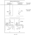
- FIG. 12 Another lightning protection apparatus provided in embodiments of this application may be shown in FIG. 12 .
- a first lightning protection unit includes a first varistor VDR 1.
- a first terminal of the VDR 1 is connected to a corresponding phase line at a to-be-protected location, and a second terminal of the VDR 1 is connected to a first terminal of a second lightning protection unit.
- the second lightning protection unit includes a second varistor VDR 2, a first gas discharge tube GDT 1, and a first resistor R1.
- a first terminal of the VDR 2 is connected to the second terminal of the VDR 1.
- a second terminal of the VDR 2 is connected to a first terminal of the GDT 1.
- a second terminal of the GDT 1 is connected to an earth wire.
- the R1 is connected in parallel to the GDT 1.
- a third lightning protection unit includes a third varistor VDR 3, a second gas discharge tube GDT 2, and a second resistor R2.
- a first terminal of the VDR 3 is connected to the second terminal of the VDR 1.
- a second terminal of the VDR 3 is connected to a first terminal of the GDT 2.
- a second terminal of the GDT 2 is connected to the earth wire.
- the R2 is connected in parallel to the GDT 2.
- the VDR 1, the VDR 2, and the GDT 1 each share a part of a voltage on the phase line.
- a voltage shared by two terminals of each of the VDR 1, the VDR 2, and the GDT 1 reaches an operating voltage.
- the VDR 1, the VDR 2, and the GDT 1 clamp the voltage on the phase line, and transmit an excessive current to the earth wire through a first conduction path constituted by the VDR 1, the VDR 2, and the GDT 1 and a second conduction path constituted by the VDR 1, the VDR 3, and the GDT 2.
- the third lightning protection unit including the VDR 3 and the GDT 2 and the first lightning protection unit may normally transmit the lightning energy on the phase line to the earth wire, to ensure safety of the to-be-protected location.
- a quantity of GDTs 1 connected in series to the VDR 2 may be increased in the second lightning protection unit, and a quantity of GDTs 2 connected in series to the VDR 3 may be increased in the third lightning protection unit.
- the lightning protection apparatus structure is merely an example. In actual application, based on different devices in the first lightning protection unit and the second lightning protection unit, the lightning protection apparatus may alternatively use another structure. Details are not described herein in this application.
- the photovoltaic power generation system 1300 includes a plurality of photovoltaic components 1301, a direct current to direct current DC/DC converter 1302, a direct current to alternating current DC/AC converter 1303, and the foregoing first lightning protection apparatus 400.
- Output terminals of the plurality of photovoltaic components 1301 are connected to an input terminal of the DC/DC converter 1302, and the plurality of photovoltaic components 1301 are configured to convert light energy into a first direct current, and output the first direct current to the DC/DC converter 1302.
- An output terminal of the DC/DC converter 1302 is connected to an input terminal of the DC/AC converter 1303, and the DC/DC converter 1302 is configured to convert the first direct current into a second direct current, and output the second direct current to the DC/AC converter 1303.
- An output terminal of the DC/AC converter 1303 is connected to a grid, and the DC/AC converter 1303 is configured to convert the second direct current into a first alternating current, and output the first alternating current to the grid.
- the first lightning protection apparatus 400 is connected to the output terminal of the DC/AC converter, and the first lightning protection apparatus 400 is configured to perform lightning protection on the photovoltaic power generation system 1300.
- the photovoltaic power generation system 1300 further includes the foregoing second lightning protection apparatuses 400 in a one-to-one correspondence with the plurality of photovoltaic components, and each second lightning protection apparatus is connected to an output terminal of a corresponding photovoltaic component.
- the second lightning protection apparatuses 400 may perform lightning protection on the plurality of photovoltaic components 1301.
- the photovoltaic power generation system 1300 further includes a third lightning protection apparatus 400 connected to the output terminal of the DC/DC converter 1302.
- the third lightning protection apparatus 400 may perform lightning protection on the DC/DC converter 1302.
- the plurality of photovoltaic components 1301 may share one second lightning protection apparatus 400.
- one third lightning protection apparatus 400 may be connected between a positive direct current bus and the neutral line M, and one third lightning protection apparatus 400 may be connected between a negative direct current bus and the neutral line M.
- lightning protection apparatus provided in this application is not limited to being used in the field of photovoltaic power generation, but can also be used in the fields such as wind power generation and hydroelectric power generation.
Landscapes
- Engineering & Computer Science (AREA)
- Microelectronics & Electronic Packaging (AREA)
- Physics & Mathematics (AREA)
- Electromagnetism (AREA)
- Emergency Protection Circuit Devices (AREA)
Priority Applications (1)
| Application Number | Priority Date | Filing Date | Title |
|---|---|---|---|
| EP25154622.2A EP4576470A3 (de) | 2021-04-09 | 2022-04-07 | Blitzschutzvorrichtung und fotovoltaisches stromerzeugungssystem |
Applications Claiming Priority (1)
| Application Number | Priority Date | Filing Date | Title |
|---|---|---|---|
| CN202110385106.8A CN113097987A (zh) | 2021-04-09 | 2021-04-09 | 一种防雷装置和光伏发电系统 |
Related Child Applications (2)
| Application Number | Title | Priority Date | Filing Date |
|---|---|---|---|
| EP25154622.2A Division EP4576470A3 (de) | 2021-04-09 | 2022-04-07 | Blitzschutzvorrichtung und fotovoltaisches stromerzeugungssystem |
| EP25154622.2A Division-Into EP4576470A3 (de) | 2021-04-09 | 2022-04-07 | Blitzschutzvorrichtung und fotovoltaisches stromerzeugungssystem |
Publications (3)
| Publication Number | Publication Date |
|---|---|
| EP4071954A1 true EP4071954A1 (de) | 2022-10-12 |
| EP4071954B1 EP4071954B1 (de) | 2025-09-03 |
| EP4071954C0 EP4071954C0 (de) | 2025-09-03 |
Family
ID=76676065
Family Applications (2)
| Application Number | Title | Priority Date | Filing Date |
|---|---|---|---|
| EP22167255.3A Active EP4071954B1 (de) | 2021-04-09 | 2022-04-07 | Blitzschutzvorrichtung und fotovoltaisches stromerzeugungssystem |
| EP25154622.2A Pending EP4576470A3 (de) | 2021-04-09 | 2022-04-07 | Blitzschutzvorrichtung und fotovoltaisches stromerzeugungssystem |
Family Applications After (1)
| Application Number | Title | Priority Date | Filing Date |
|---|---|---|---|
| EP25154622.2A Pending EP4576470A3 (de) | 2021-04-09 | 2022-04-07 | Blitzschutzvorrichtung und fotovoltaisches stromerzeugungssystem |
Country Status (3)
| Country | Link |
|---|---|
| US (1) | US11855449B2 (de) |
| EP (2) | EP4071954B1 (de) |
| CN (2) | CN113097987A (de) |
Cited By (1)
| Publication number | Priority date | Publication date | Assignee | Title |
|---|---|---|---|---|
| CN116169657A (zh) * | 2023-02-22 | 2023-05-26 | 深圳市拓普泰克技术股份有限公司 | 一种智能光伏防雷控制系统 |
Families Citing this family (9)
| Publication number | Priority date | Publication date | Assignee | Title |
|---|---|---|---|---|
| WO2023162262A1 (ja) * | 2022-02-28 | 2023-08-31 | 日本電信電話株式会社 | 雷防護装置および雷防護方法 |
| US12003097B2 (en) * | 2022-08-30 | 2024-06-04 | Robe Lighting S.R.O. | Detecting and reporting the status of an overvoltage protection device |
| CN115986705B (zh) * | 2022-12-21 | 2024-09-13 | 国网电力科学研究院武汉南瑞有限责任公司 | 一种直流输电线路雷击过电压限制的方法、装置、媒体及系统 |
| CN116094450A (zh) * | 2022-12-27 | 2023-05-09 | 华为数字能源技术有限公司 | 一种光伏逆变系统及防雷装置 |
| CN116317512A (zh) | 2023-03-02 | 2023-06-23 | 华为数字能源技术有限公司 | 功率变换设备 |
| JPWO2025023029A1 (de) * | 2023-07-26 | 2025-01-30 | ||
| CN117728660A (zh) * | 2023-11-02 | 2024-03-19 | 华为数字能源技术有限公司 | 功率变换装置 |
| CN118889354A (zh) * | 2024-09-05 | 2024-11-01 | 深圳市华浩德电子有限公司 | 一种非隔离高安规耐压低共模雷击残压的控制电路 |
| DE102024130334A1 (de) * | 2024-10-18 | 2026-04-23 | Tdk Electronics Ag | Überspannungsschutzschaltung |
Citations (7)
| Publication number | Priority date | Publication date | Assignee | Title |
|---|---|---|---|---|
| EP1075064A1 (de) * | 1999-07-09 | 2001-02-07 | Leutron GmbH | Blitz- und Überspannungsschutzeinrichtung |
| US20090154034A1 (en) * | 2007-12-18 | 2009-06-18 | Tallam Rangarajan M | Motor drive with low leakage surge protection |
| CN206226006U (zh) * | 2016-11-18 | 2017-06-06 | 华北电力大学 | 一种光伏防雷电路 |
| CN107887899A (zh) * | 2017-12-23 | 2018-04-06 | 珠海德利和电气有限公司 | 一种避雷保护电路 |
| US20190148935A1 (en) * | 2017-11-15 | 2019-05-16 | Fanuc Corporation | Surge protective circuit and surge protective device |
| CN112467705A (zh) * | 2019-09-06 | 2021-03-09 | 阳光电源股份有限公司 | 防雷保护装置及逆变器 |
| EP3832825A1 (de) * | 2018-11-28 | 2021-06-09 | Xiamen Set Electronics Co., Ltd | Überspannungsschutzvorrichtung und -system |
Family Cites Families (16)
| Publication number | Priority date | Publication date | Assignee | Title |
|---|---|---|---|---|
| CN2255691Y (zh) * | 1996-01-09 | 1997-06-04 | 伍永康 | 单相电源防雷保护装置 |
| AUPO605397A0 (en) | 1997-04-07 | 1997-05-01 | Erico Lightning Technologies Pty Ltd | Improvements in transient overvoltage and lightning protection of power connected equipment |
| CN1146096C (zh) * | 2001-12-05 | 2004-04-14 | 沈艺明 | 一种电源防雷器 |
| JP4901522B2 (ja) * | 2007-02-19 | 2012-03-21 | 株式会社サンコーシヤ | サージ防護デバイス及びそれを用いたサージ保護装置 |
| ES2509142T5 (es) * | 2009-05-26 | 2018-06-04 | Sma Solar Technology Ag | Protección contra sobretensiones para convertidores con filtro EMV de entrada |
| US8045314B2 (en) * | 2009-08-01 | 2011-10-25 | The Travis Business Group, Inc. | Method of atmospheric discharge energy conversion, storage and distribution |
| CN201541126U (zh) * | 2009-10-16 | 2010-08-04 | 上海臻和防雷电气技术有限责任公司 | 太阳能发电装置的防雷保护系统 |
| US8390977B2 (en) * | 2010-02-26 | 2013-03-05 | Advanced Energy Industries, Inc | Solar power inverters, including solar power inverters having surge protective devices, and associated methods |
| CN201846074U (zh) * | 2010-11-03 | 2011-05-25 | 英利能源(中国)有限公司 | 光伏发电系统防雷电控制装置 |
| CN201994657U (zh) * | 2011-03-03 | 2011-09-28 | 英利能源(中国)有限公司 | 具有避雷装置的光伏组件 |
| CN202076965U (zh) * | 2011-06-09 | 2011-12-14 | 湖南浦洋节能科技股份有限公司 | 一种新型防雷太阳能供电系统 |
| DE102015108652A1 (de) * | 2015-06-01 | 2016-12-01 | Ebm-Papst Mulfingen Gmbh & Co. Kg | Überspannungsschutzschaltung |
| CN205407246U (zh) * | 2016-03-09 | 2016-07-27 | 南京擎雷电子有限公司 | 一种光伏防雷模块 |
| CN208862564U (zh) * | 2018-07-18 | 2019-05-14 | 河南森源电气股份有限公司 | 一种光伏逆变器防雷保护装置 |
| CN209217711U (zh) * | 2018-11-06 | 2019-08-06 | 普联技术有限公司 | 一种防雷保护电路及电源适配器 |
| CN109390925B (zh) | 2019-01-03 | 2020-08-28 | 阳光电源股份有限公司 | 逆变器防雷保护方法、电路和装置及逆变器并网系统 |
-
2021
- 2021-04-09 CN CN202110385106.8A patent/CN113097987A/zh active Pending
- 2021-04-09 CN CN202311627042.3A patent/CN117878860A/zh active Pending
-
2022
- 2022-04-07 EP EP22167255.3A patent/EP4071954B1/de active Active
- 2022-04-07 EP EP25154622.2A patent/EP4576470A3/de active Pending
- 2022-04-08 US US17/716,483 patent/US11855449B2/en active Active
Patent Citations (7)
| Publication number | Priority date | Publication date | Assignee | Title |
|---|---|---|---|---|
| EP1075064A1 (de) * | 1999-07-09 | 2001-02-07 | Leutron GmbH | Blitz- und Überspannungsschutzeinrichtung |
| US20090154034A1 (en) * | 2007-12-18 | 2009-06-18 | Tallam Rangarajan M | Motor drive with low leakage surge protection |
| CN206226006U (zh) * | 2016-11-18 | 2017-06-06 | 华北电力大学 | 一种光伏防雷电路 |
| US20190148935A1 (en) * | 2017-11-15 | 2019-05-16 | Fanuc Corporation | Surge protective circuit and surge protective device |
| CN107887899A (zh) * | 2017-12-23 | 2018-04-06 | 珠海德利和电气有限公司 | 一种避雷保护电路 |
| EP3832825A1 (de) * | 2018-11-28 | 2021-06-09 | Xiamen Set Electronics Co., Ltd | Überspannungsschutzvorrichtung und -system |
| CN112467705A (zh) * | 2019-09-06 | 2021-03-09 | 阳光电源股份有限公司 | 防雷保护装置及逆变器 |
Cited By (1)
| Publication number | Priority date | Publication date | Assignee | Title |
|---|---|---|---|---|
| CN116169657A (zh) * | 2023-02-22 | 2023-05-26 | 深圳市拓普泰克技术股份有限公司 | 一种智能光伏防雷控制系统 |
Also Published As
| Publication number | Publication date |
|---|---|
| EP4576470A2 (de) | 2025-06-25 |
| CN117878860A (zh) | 2024-04-12 |
| EP4071954B1 (de) | 2025-09-03 |
| EP4071954C0 (de) | 2025-09-03 |
| US20220329064A1 (en) | 2022-10-13 |
| US11855449B2 (en) | 2023-12-26 |
| CN113097987A (zh) | 2021-07-09 |
| EP4576470A3 (de) | 2025-10-22 |
Similar Documents
| Publication | Publication Date | Title |
|---|---|---|
| EP4071954A1 (de) | Blitzschutzvorrichtung und fotovoltaisches stromerzeugungssystem | |
| CN111987706B (zh) | 一种限流型可控避雷器、换流器、输电系统以及控制方法 | |
| US9972997B2 (en) | Circuit interruption device | |
| RU2479906C2 (ru) | Защитное устройство | |
| US20230086269A1 (en) | Fault protection apparatus | |
| WO2024221679A1 (zh) | 一种含多组并联氧化锌电阻片柱的消能装置及其使用方法 | |
| EP4436038A1 (de) | Fotovoltaisches umkehrsystem und blitzschutzvorrichtung | |
| CN102545145A (zh) | 用于保护功耗电路的系统和方法 | |
| US12244222B2 (en) | Power conversion circuit, power transmission system, and photovoltaic device | |
| KR102894595B1 (ko) | 전력 전송 | |
| US11159094B2 (en) | Converter arrangement having a phase module arrester and method for short-circuit protection thereof | |
| US20220320870A1 (en) | Direct current power supply system, photovoltaic system, energy storage system, and optical storage system | |
| EP3416256A1 (de) | Oberschwingungsfilter und schutzsystem eines hochspannungsgleichstromwandlers | |
| CN108879637B (zh) | 混合直流高低压换流器连接母线处避雷器参数设计方法 | |
| CN219322085U (zh) | 储能装置及其储能子模块 | |
| CN207475264U (zh) | 保护电路以及十二脉冲充电装置 | |
| CN120237588B (zh) | 电源线的检测保护装置、电连接设备及用电设备 | |
| CN218276461U (zh) | 一种静态整流桥的交流侧浪涌过压保护装置 | |
| CN224021462U (zh) | 防护电路和电源 | |
| CN218514092U (zh) | 一种并联电源输出电压补偿电路 | |
| US20240329154A1 (en) | System for protecting an electrical circuit for an aircraft | |
| CN213461127U (zh) | 应用于物联网设备的输入电源保护电路 | |
| WO1984002807A1 (en) | Direct current cable protection system | |
| CN211377974U (zh) | 一种带防雷功能的光伏接线盒 | |
| CN119182104A (zh) | 一种浪涌耐压双保护电路 |
Legal Events
| Date | Code | Title | Description |
|---|---|---|---|
| PUAI | Public reference made under article 153(3) epc to a published international application that has entered the european phase |
Free format text: ORIGINAL CODE: 0009012 |
|
| STAA | Information on the status of an ep patent application or granted ep patent |
Free format text: STATUS: THE APPLICATION HAS BEEN PUBLISHED |
|
| AK | Designated contracting states |
Kind code of ref document: A1 Designated state(s): AL AT BE BG CH CY CZ DE DK EE ES FI FR GB GR HR HU IE IS IT LI LT LU LV MC MK MT NL NO PL PT RO RS SE SI SK SM TR |
|
| STAA | Information on the status of an ep patent application or granted ep patent |
Free format text: STATUS: REQUEST FOR EXAMINATION WAS MADE |
|
| 17P | Request for examination filed |
Effective date: 20230221 |
|
| RBV | Designated contracting states (corrected) |
Designated state(s): AL AT BE BG CH CY CZ DE DK EE ES FI FR GB GR HR HU IE IS IT LI LT LU LV MC MK MT NL NO PL PT RO RS SE SI SK SM TR |
|
| STAA | Information on the status of an ep patent application or granted ep patent |
Free format text: STATUS: EXAMINATION IS IN PROGRESS |
|
| 17Q | First examination report despatched |
Effective date: 20230519 |
|
| GRAP | Despatch of communication of intention to grant a patent |
Free format text: ORIGINAL CODE: EPIDOSNIGR1 |
|
| STAA | Information on the status of an ep patent application or granted ep patent |
Free format text: STATUS: GRANT OF PATENT IS INTENDED |
|
| INTG | Intention to grant announced |
Effective date: 20241016 |
|
| GRAJ | Information related to disapproval of communication of intention to grant by the applicant or resumption of examination proceedings by the epo deleted |
Free format text: ORIGINAL CODE: EPIDOSDIGR1 |
|
| STAA | Information on the status of an ep patent application or granted ep patent |
Free format text: STATUS: EXAMINATION IS IN PROGRESS |
|
| INTC | Intention to grant announced (deleted) | ||
| GRAP | Despatch of communication of intention to grant a patent |
Free format text: ORIGINAL CODE: EPIDOSNIGR1 |
|
| STAA | Information on the status of an ep patent application or granted ep patent |
Free format text: STATUS: GRANT OF PATENT IS INTENDED |
|
| GRAS | Grant fee paid |
Free format text: ORIGINAL CODE: EPIDOSNIGR3 |
|
| INTG | Intention to grant announced |
Effective date: 20250626 |
|
| GRAA | (expected) grant |
Free format text: ORIGINAL CODE: 0009210 |
|
| STAA | Information on the status of an ep patent application or granted ep patent |
Free format text: STATUS: THE PATENT HAS BEEN GRANTED |
|
| AK | Designated contracting states |
Kind code of ref document: B1 Designated state(s): AL AT BE BG CH CY CZ DE DK EE ES FI FR GB GR HR HU IE IS IT LI LT LU LV MC MK MT NL NO PL PT RO RS SE SI SK SM TR |
|
| REG | Reference to a national code |
Ref country code: CH Ref legal event code: EP |
|
| REG | Reference to a national code |
Ref country code: DE Ref legal event code: R096 Ref document number: 602022020538 Country of ref document: DE |
|
| REG | Reference to a national code |
Ref country code: IE Ref legal event code: FG4D |
|
| U01 | Request for unitary effect filed |
Effective date: 20250911 |
|
| U07 | Unitary effect registered |
Designated state(s): AT BE BG DE DK EE FI FR IT LT LU LV MT NL PT RO SE SI Effective date: 20250917 |
|
| PG25 | Lapsed in a contracting state [announced via postgrant information from national office to epo] |
Ref country code: NO Free format text: LAPSE BECAUSE OF FAILURE TO SUBMIT A TRANSLATION OF THE DESCRIPTION OR TO PAY THE FEE WITHIN THE PRESCRIBED TIME-LIMIT Effective date: 20251203 |
|
| PG25 | Lapsed in a contracting state [announced via postgrant information from national office to epo] |
Ref country code: HR Free format text: LAPSE BECAUSE OF FAILURE TO SUBMIT A TRANSLATION OF THE DESCRIPTION OR TO PAY THE FEE WITHIN THE PRESCRIBED TIME-LIMIT Effective date: 20250903 |
|
| PG25 | Lapsed in a contracting state [announced via postgrant information from national office to epo] |
Ref country code: GR Free format text: LAPSE BECAUSE OF FAILURE TO SUBMIT A TRANSLATION OF THE DESCRIPTION OR TO PAY THE FEE WITHIN THE PRESCRIBED TIME-LIMIT Effective date: 20251204 |
|
| PG25 | Lapsed in a contracting state [announced via postgrant information from national office to epo] |
Ref country code: PL Free format text: LAPSE BECAUSE OF FAILURE TO SUBMIT A TRANSLATION OF THE DESCRIPTION OR TO PAY THE FEE WITHIN THE PRESCRIBED TIME-LIMIT Effective date: 20250903 |
|
| PG25 | Lapsed in a contracting state [announced via postgrant information from national office to epo] |
Ref country code: RS Free format text: LAPSE BECAUSE OF FAILURE TO SUBMIT A TRANSLATION OF THE DESCRIPTION OR TO PAY THE FEE WITHIN THE PRESCRIBED TIME-LIMIT Effective date: 20251203 |
|
| PG25 | Lapsed in a contracting state [announced via postgrant information from national office to epo] |
Ref country code: ES Free format text: LAPSE BECAUSE OF FAILURE TO SUBMIT A TRANSLATION OF THE DESCRIPTION OR TO PAY THE FEE WITHIN THE PRESCRIBED TIME-LIMIT Effective date: 20250903 |
|
| PG25 | Lapsed in a contracting state [announced via postgrant information from national office to epo] |
Ref country code: SM Free format text: LAPSE BECAUSE OF FAILURE TO SUBMIT A TRANSLATION OF THE DESCRIPTION OR TO PAY THE FEE WITHIN THE PRESCRIBED TIME-LIMIT Effective date: 20250903 |
|
| PG25 | Lapsed in a contracting state [announced via postgrant information from national office to epo] |
Ref country code: IS Free format text: LAPSE BECAUSE OF FAILURE TO SUBMIT A TRANSLATION OF THE DESCRIPTION OR TO PAY THE FEE WITHIN THE PRESCRIBED TIME-LIMIT Effective date: 20260103 |
|
| PG25 | Lapsed in a contracting state [announced via postgrant information from national office to epo] |
Ref country code: CZ Free format text: LAPSE BECAUSE OF FAILURE TO SUBMIT A TRANSLATION OF THE DESCRIPTION OR TO PAY THE FEE WITHIN THE PRESCRIBED TIME-LIMIT Effective date: 20250903 |
|
| PG25 | Lapsed in a contracting state [announced via postgrant information from national office to epo] |
Ref country code: SK Free format text: LAPSE BECAUSE OF FAILURE TO SUBMIT A TRANSLATION OF THE DESCRIPTION OR TO PAY THE FEE WITHIN THE PRESCRIBED TIME-LIMIT Effective date: 20250903 |