EP4072054B1 - Verfahren zur uplink-kanal-übertragung, endgerät und basisstation - Google Patents
Verfahren zur uplink-kanal-übertragung, endgerät und basisstation Download PDFInfo
- Publication number
- EP4072054B1 EP4072054B1 EP20897577.1A EP20897577A EP4072054B1 EP 4072054 B1 EP4072054 B1 EP 4072054B1 EP 20897577 A EP20897577 A EP 20897577A EP 4072054 B1 EP4072054 B1 EP 4072054B1
- Authority
- EP
- European Patent Office
- Prior art keywords
- symbol
- uplink channels
- transmission
- channel
- channels
- Prior art date
- Legal status (The legal status is an assumption and is not a legal conclusion. Google has not performed a legal analysis and makes no representation as to the accuracy of the status listed.)
- Active
Links
Images



Classifications
-
- H—ELECTRICITY
- H04—ELECTRIC COMMUNICATION TECHNIQUE
- H04L—TRANSMISSION OF DIGITAL INFORMATION, e.g. TELEGRAPHIC COMMUNICATION
- H04L5/00—Arrangements affording multiple use of the transmission path
- H04L5/0001—Arrangements for dividing the transmission path
- H04L5/0003—Two-dimensional division
- H04L5/0005—Time-frequency
- H04L5/0007—Time-frequency the frequencies being orthogonal, e.g. OFDM(A) or DMT
- H04L5/0008—Wavelet-division
-
- H—ELECTRICITY
- H04—ELECTRIC COMMUNICATION TECHNIQUE
- H04W—WIRELESS COMMUNICATION NETWORKS
- H04W72/00—Local resource management
- H04W72/12—Wireless traffic scheduling
- H04W72/1263—Mapping of traffic onto schedule, e.g. scheduled allocation or multiplexing of flows
- H04W72/1268—Mapping of traffic onto schedule, e.g. scheduled allocation or multiplexing of flows of uplink data flows
-
- H—ELECTRICITY
- H04—ELECTRIC COMMUNICATION TECHNIQUE
- H04L—TRANSMISSION OF DIGITAL INFORMATION, e.g. TELEGRAPHIC COMMUNICATION
- H04L5/00—Arrangements affording multiple use of the transmission path
- H04L5/003—Arrangements for allocating sub-channels of the transmission path
- H04L5/0044—Allocation of payload; Allocation of data channels, e.g. PDSCH or PUSCH
-
- H—ELECTRICITY
- H04—ELECTRIC COMMUNICATION TECHNIQUE
- H04L—TRANSMISSION OF DIGITAL INFORMATION, e.g. TELEGRAPHIC COMMUNICATION
- H04L5/00—Arrangements affording multiple use of the transmission path
- H04L5/003—Arrangements for allocating sub-channels of the transmission path
- H04L5/0053—Allocation of signalling, i.e. of overhead other than pilot signals
-
- H—ELECTRICITY
- H04—ELECTRIC COMMUNICATION TECHNIQUE
- H04L—TRANSMISSION OF DIGITAL INFORMATION, e.g. TELEGRAPHIC COMMUNICATION
- H04L5/00—Arrangements affording multiple use of the transmission path
- H04L5/003—Arrangements for allocating sub-channels of the transmission path
- H04L5/0053—Allocation of signalling, i.e. of overhead other than pilot signals
- H04L5/0055—Physical resource allocation for ACK/NACK
-
- H—ELECTRICITY
- H04—ELECTRIC COMMUNICATION TECHNIQUE
- H04L—TRANSMISSION OF DIGITAL INFORMATION, e.g. TELEGRAPHIC COMMUNICATION
- H04L5/00—Arrangements affording multiple use of the transmission path
- H04L5/0091—Signalling for the administration of the divided path, e.g. signalling of configuration information
- H04L5/0094—Indication of how sub-channels of the path are allocated
-
- H—ELECTRICITY
- H04—ELECTRIC COMMUNICATION TECHNIQUE
- H04W—WIRELESS COMMUNICATION NETWORKS
- H04W72/00—Local resource management
- H04W72/20—Control channels or signalling for resource management
-
- H—ELECTRICITY
- H04—ELECTRIC COMMUNICATION TECHNIQUE
- H04L—TRANSMISSION OF DIGITAL INFORMATION, e.g. TELEGRAPHIC COMMUNICATION
- H04L5/00—Arrangements affording multiple use of the transmission path
- H04L5/0001—Arrangements for dividing the transmission path
- H04L5/0003—Two-dimensional division
- H04L5/0005—Time-frequency
-
- H—ELECTRICITY
- H04—ELECTRIC COMMUNICATION TECHNIQUE
- H04W—WIRELESS COMMUNICATION NETWORKS
- H04W28/00—Network traffic management; Network resource management
- H04W28/02—Traffic management, e.g. flow control or congestion control
- H04W28/0252—Traffic management, e.g. flow control or congestion control per individual bearer or channel
-
- H—ELECTRICITY
- H04—ELECTRIC COMMUNICATION TECHNIQUE
- H04W—WIRELESS COMMUNICATION NETWORKS
- H04W72/00—Local resource management
- H04W72/20—Control channels or signalling for resource management
- H04W72/23—Control channels or signalling for resource management in the downlink direction of a wireless link, i.e. towards a terminal
Definitions
- the present application relates to the technical field of communication, and in particular, to a method for uplink channel transmission, a terminal, and a base station.
- PUCCH Physical Uplink Control Channel
- PUSCH Physical Uplink Shared Channel
- UCI uplink control information
- HARQ-ACK hybrid automatic repeat request-acknowledge character
- CSI channel state information
- SR scheduling request
- a PUSCH may be selected from the multiple PUSCHs according to a predetermined rule, for example, the PUSCH carrying aperiodic channel state information (A-CSI) (if any) is preferentially selected.
- A-CSI aperiodic channel state information
- a PUSCH with a corresponding physical downlink control channel is preferentially selected.
- PUSCHs of the same type for example, PUSCHs with corresponding PDCCHs, or PUSCHs without corresponding PDCCHs if there is no PUSCH with a corresponding PDCCH
- the PUSCH on a carrier having the smallest carrier number is selected, and the PUSCH earliest in time is selected when there are multiple overlapped PUSCHs and PUCCHs on the selected carrier.
- the PUCCHs carrying the UCI overlap in time domain, it is also required to determine whether the first symbol of the earliest initial channel in the overlapped PUCCHs satisfies the predefined timeline.
- the predefined timeline is satisfied, the UCIs on a plurality of PUCCHs can be transmitted in combination in a PUCCH channel, thereby avoiding parallel transmissions of the plurality of PUCCHs. It is defined in R15 that there is no case where the timeline is not satisfied, that is, the case where the timeline is not satisfied is an incorrect scheduling and no cation is performed.
- scheduling and configurations are performed in the respective base stations, it is required to ensure that the overlapped channels always satisfy the timeline.
- US2017135090A1 discloses a user equipment (UE) for reporting uplink control information (UCI) when one or more Licensed-Assisted Access (LAA) serving cells are configured.
- the UE includes a processor and memory in electronic communication with the processor. Instructions stored in the memory are executable to determine if physical uplink shared channel (PUSCH) transmissions are scheduled on LAA serving cells and licensed cells. The instructions are also executable to determine a type of UCI to be reported. The instructions are further executable to determine a channel and cells to carry different UCI. The instructions are additionally executable to transmit the channel on the cells determined to carry UCI. The instructions are also executable to determine whether a LAA PUSCH is transmitted and UCI is multiplexed. The instructions are further executable to drop LAA PUSCH or transmit LAA PUSCH subject to listen-before-talk (LBT).
- LBT listen-before-talk
- KR20170112633A discloses a method and apparatus for multiplexing transmission of an uplink control channel and transmission of a sounding reference signal in an unlicensed spectrum of a wireless communication system.
- EP2660992A1 discloses a method and a device for transmitting data.
- the method includes: a UE determining, according to a preset rule, whether to transmit PUCCH data and/or PUSCH data and/or an SRS or not on a last symbol of a current subframe; the UE determining the PUCCH data and/or the PUSCH data to be transmitted on the current subframe according to availability of the last symbol of the current subframe for transmitting the PUCCH data and/or the PUSCH data; and the UE transmitting the PUCCH data and/or the PUSCH data on the current subframe and/or transmitting the SRS on the last symbol of the current subframe.
- US20190261391A1 discloses an apparatus of a user equipment (UE) to operate in a New Radio (NR) system, which comprises one or more baseband processors to determine if two or more uplink signals partially overlap, determine a multiplexing rule, a dropping rule, or a priority rule for the two or more uplink signals, and to multiplex, drop, or prioritize the two or more uplink signals for transmission according to the multiplexing rule, dropping rule, or priority rule, and a memory to store two or more uplink signals.
- NR New Radio
- Embodiments of the present application provide a method for uplink channel transmission, a terminal, and a base station, for ensuring normal transmission of a system when the uplink channels overlap and improving transmission performance of the system.
- the invention is limited by the appended set of independent claims. Further embodiments are defined by the dependent claims.
- the PUCCH carrying HARQ-ACK uses PUCCH format 0, and the PUCCH carrying SR can use either format 0 or format 1, the SR and HARQ-ACK are multiplexed and transmitted on the PUCCH resource of HARQ-ACK. That is, the HARQ-ACK is transmitted on the PUCCH resource of the HARQ-ACK by selecting a cyclic shift (CS) corresponding to the HARQ-ACK depend on whether a positive SR or a negative SR exists, which is implicitly indicated as positive or negative.
- CS cyclic shift
- the PUCCH carrying SR uses format 1 and the PUCCH carrying HARQ-ACK uses format 1, HARQ-ACK is transmitted on the PUCCH resource of SR when SR is a positive, such that the simultaneous transmission of SR is implicitly indicated by transmitting HARQ-ACK using the PUCCH resource corresponding to SR, otherwise (i.e., negative SR), the HARQ-ACK is transmitted on the PUCCH resource of the HARQ-ACK.
- a set of PUCCH resources is determined according to the total number of bits of the SR and HARQ-ACK.
- DCI Downlink Control Information
- a PUCCH resource is determined from the determined set of PUCCH resources for simultaneously transmitting the SR and HARQ -ACK, wherein SR is X bits, indicating SR status of X SRs overlapping with the HARQ-ACK (which one is positive, or both are negative). That is, whether SR is positive or negative, X-bit SR is always transmitted, so as to avoid change of the number of bits of UCI transmitted on the PUCCH resource of the HARQ-ACK due to the SR state.
- DCI Downlink Control Information
- SPS semi-persistent scheduling
- PDCCH carrying HARQ-ACK with a corresponding PDCCH that is, when the HARQ-ACK is feedback information of PDSCH, the PDCCH that schedules the PDSCH corresponds to the HARQ-ACK, and when the HARQ-ACK is feedback information of the PDCCH indicating release of downlink SPS resources, the PDCCH corresponds to the HARQ-ACK
- a set of PUCCH resources is selected from a plurality of sets of PUCCH resources according to the total number of bits of the SR and HARQ-ACK; and a PUCCH resource is determined from the selected set of PUCCH resources for simultaneously carrying the HARQ-ACK and CSI, according to a PUCCH resource indication field in DCI corresponding to the HARQ-ACK.
- the re-determined PUCCH resource may be the same as or different from the original PUCCH resource carrying the HARQ-ACK (if different, it is a new PUCCH resource). It is not expected that the terminal is configured to support simultaneous transmission of the HARQ-ACK and CSI when only one set of PUCCH resources is configured.
- the PUCCHs in a time slot constitute a set Q
- an uplink channel in the set Q which starts earliest is determined as channel A
- a set X of channels that overlap with channel A is determined.
- Above-mentioned multiplexing transmission rules are applied to UCI on channel A and channel X to obtain a channel resource for multiplexing transmission, and channel A in the set Q and channel X are replaced with the channel resource for multiplexing transmission.
- the above steps are repeated to determine channel A and channel X in a new set Q and so on, until a plurality of PUCCHs that do not overlap in time domain are obtained.
- the HARQ-ACK carried on the PUCCH is a HARQ-ACK of the PDSCH scheduled by DCI or is an DCI indicating release of a downlink SPS resource
- the DCI scheduling PDSCH or the DCI indicating the release of downlink SPS resource is the DCI corresponding to the PUCCH
- the DCI scheduling the PUSCH is the DCI corresponding to the PUSCH
- the first symbol of the channel among the overlapped channels that starts earliest needs to meet the following timelines.
- Timeline1 the first symbol is not earlier than a symbol including a cyclic prefix (CP) starting later T1 time after the last symbol of any PDSCH or SPS PDSCH release that requires HARQ-ACK feedback on PUCCH, that is, a time interval between the first symbol and the last symbol of any of the above PDSCH or SPS PDSCH release is not less than T1 time.
- T1 is related to a processing delay of PDSCH or SPS PDSCH release and can be calculated according to the formula and related parameters.
- the timeline is intended to ensure that the acquisition and preparation of the HARQ-ACK can be completed before the transmission of the finally determined channel for transmitting the HARQ-ACK starts.
- Timeline2 the first symbol is not earlier than a symbol including a CP starting later T2 time after the last symbol of any PDCCH (including the PDCCH indicating SPS PDSCH release) scheduling PDSCH (if any) and PUSCH (if any), that is, a time interval between the first symbol and the last symbol of any of above PDCCHs is not less than T2 time.
- T2 is related to the processing delay of PUSCH and can be calculated according to the formula and related parameters.
- the timeline is intended to ensure that when there are a plurality of UCI multiplexing transmissions, the acquisition and multiplexing processing of the various UCIs can be completed before the transmission of the target channel for transmitting the UCI starts.
- FIGS. 1-1 to 1-4 that is, FIG. 1-1, FIG. 1-2, FIG. 1-3 , and FIG. 1-4
- a PDCCH scheduling PDSCH DL DCI in the figures
- a PDCCH scheduling PUSCH UL DCI in the figures.
- the HARQ-ACK carried on the PUCCH has no corresponding DCI (that is, the HARQ-ACK is the HARQ-ACK of the SPS PDSCH), in which case there is no DL DCI in the FIGS. 1-1 and 1-2 , and if the PUSCH also has no corresponding DCI, in which case there is no DL DCI in the FIGS. 1-1 and 1-2 , only T1 needs to be checked and T2 does not need to be checked. If the PUCCH overlaps with the PUSCH and the PUCCH carries CSI and/or SR, T1 does not need to be checked, and further, if the PUSCH has no corresponding DCI, T2 does not need to be checked.
- CSI may include aperiodic CSI (A-CSI), semi-persistent CSI (SP-CSI), periodic CSI (P-CSI), which have the priorities of A-CSI, SP-CSI CSI, P-CSI from high to low.
- A-CSI aperiodic CSI
- SP-CSI semi-persistent CSI
- P-CSI periodic CSI
- the terminal side may perform uplink channel transmission through any one of the following two processing modes.
- Mode 1 includes the following steps: step 201: firstly processing the plurality of uplink channels based on a multiplexing rule to determine one or more first target uplink channels to be transmitted, and then determining whether to transmit the one or more first target uplink channels.
- an order of processes for processing the plurality of uplink channels based on the multiplexing rule and for determining whether to transmit the uplink channels is clearly defined, such that the terminal can directly determine the transmission status of the uplink channels according to the order, thereby ensuring the normal transmission of a system.
- Mode 2 includes the following steps: step 301: firstly determining, from the plurality of uplink channels, candidate uplink channels which could be transmitted, and then processing the candidate uplink channels based on a multiplexing rule to determine one or more second target uplink channels to be transmitted.
- this mode specifically, by firstly determining, from the plurality of uplink channels, candidate uplink channels which could be transmitted and then processing the candidate uplink channels based on a multiplexing rule to determine the one or more second target uplink channels to be transmitted, an order of processes for determining whether to transmit the uplink channel and for processing the plurality of uplink channels based on the multiplexing rules is clearly determined, such that a terminal can directly determine the transmission status of the uplink channels according to the order, thereby ensuring the normal transmission of a system.
- the terminal can clearly determine a transmission status of the uplink channels based on the determined order of the processes for determining whether to transmit the uplink channel and for processing the plurality of uplink channels based on the multiplexing rule, thereby ensuring the normal transmission of a system and improving the transmission performance
- Mode 1 when determining whether to transmit the first target uplink channels, it may be checked whether the symbol set in which transmission of the one or more first target uplink channels is located includes a first unavailable symbol. When the symbol set in which the one or more first target uplink channels is located does not include the first unavailable symbol, it is determined to transmit the one or more first target uplink channels.
- the symbol set in which the one or more first target uplink channels is located includes a first unavailable symbol, it is determined not to transmit the one or more first target uplink channels.
- the first unavailable symbol may include at least one of the following symbols: a downlink (DL) symbol configured by a higher layer signaling, a flexible (FL) symbol configured by a higher layer signaling, a symbol scheduled by DCI for downlink transmission, a symbol indicated as DL or FL by indication information in DCI for indicating a structure of a time unit, a symbol for a guard period (referred to as GP), a symbol for a synchronization signal block (referred to as SSB) transmission, an unavailable symbol preconfigured by signaling or a symbol within bandwidth part (referred to as BWP) switching time.
- DL downlink
- FL flexible
- a symbol scheduled by DCI for downlink transmission a symbol indicated as DL or FL by indication information in DCI for indicating a structure of a time unit
- GP symbol for a guard period
- SSB synchronization signal block
- BWP bandwidth part
- the DCI for indicating the structure of the time unit is specifically a DCI for carrying indication information indicating the uplink and downlink structures, for example, DCI format 2-0 scrambled using a slot format indicator-radio network temporary identity (simply referred to as SFI-RNTI).
- the action of DCI scheduling for downlink transmission may include action of instructing the terminal to receive PDSCH or channel state information reference signal (CSI-RS for short) by DCI format 1_0, DCI format 1_1 or DCI format 0_1.
- CSI-RS channel state information reference signal
- the uplink channel when determining, from the plurality of uplink channels, candidate uplink channels which could be transmitted, for each uplink channel of the plurality of uplink channels, it may also be possible to detect whether the symbol set in which the uplink channel is located includes a second unavailable symbol. When the symbol set in which the uplink channel is located does not include the second unavailable symbol, the uplink channel may be determined as a candidate uplink channel. When the symbol set in which the uplink channel is located includes the second unavailable symbol, the uplink channel cannot be determined as a candidate uplink channel.
- the second unavailable symbol may similarly include at least one of the following symbols: a DL symbol configured by a higher layer signaling, a FL symbol configured by a higher layer signaling, a symbol scheduled by DCI for downlink transmission, a symbol indicated as DL or FL by indication information in DCI for indicating a structure of a time unit, a symbol for a GP, a symbol for a SSB transmission, an unavailable symbol preconfigured by signaling or a symbol within BWP switching time.
- the symbol set in which the one or more second target uplink channels is located includes a third unavailable symbol.
- the symbol set in which the second target uplink channel is located does not include a third unavailable symbol, it is determined to transmit the one or more second target uplink channels.
- the symbol set in which the one or more second target uplink channels is located includes the third unavailable symbol, it is determined not to transmit the one or more second target uplink channels.
- the third unavailable symbol may include at least one of the following symbols: a DL symbol configured by a higher layer signaling, a FL symbol configured by a higher layer signaling, a symbol scheduled by DCI for downlink transmission, a symbol indicated as DL or FL by indication information in DCI for indicating a structure of a time unit, a symbol for a GP, a symbol for a SSB transmission, an unavailable symbol preconfigured by signaling or a symbol within BWP switching time.
- first unavailable symbol and the second unavailable symbol may be the same or different from each other, which are not specifically limited here.
- second unavailable symbol and the third unavailable symbol may be the same or different from each other, which is also not specifically limited here.
- the first unavailable symbol may include at least a DL symbol configured by a higher layer signaling, a symbol scheduled by DCI for downlink transmission, a symbol indicated as DL or FL by indication information in DCI for indicating a structure of a time unit, and a symbol for a SSB transmission
- the second unavailable symbol may be the same as the first unavailable symbol or may include at least a DL symbol configured by a higher layer signaling and a symbol for a SSB transmission.
- the third unavailable symbol may include at least a DL symbol configured by a higher layer signaling, a symbol scheduled by DCI for downlink transmission, a symbol indicated as DL or FL by indication information in DCI for indicating a structure of a time unit and a symbol for a SSB transmission.
- the plurality of uplink channels in the present embodiment include at least one channel configured by a higher layer signaling for transmission, that is, a semi-static channel.
- each of the one or more first target uplink channels is a channel configured by a higher layer signaling for transmission, and when each of the first target uplink channels is a channel configured by the higher layer signaling for transmission, it is determined to transmit the one or more first target uplink channels.
- the candidate uplink channels which could be transmitted may be determined from the channels configured by the higher layer signaling for transmission.
- the channel configured by a higher layer signaling for transmission may include at least one of the following channels: a PUSCH without a corresponding PDCCH, a PUCCH transmission using a PUCCH resource corresponding to SPS, a PUCCH transmission using a PUCCH resource corresponding to CSI, or a PUCCH transmission using a PUCCH resource corresponding to a SR.
- the PUSCH not corresponding to the PDCCH may include a cell group PUSCH (referred to as CG PUSCH) and a PUSCH carrying semi-persistent channel state information (referred to as SP-CSI).
- the PUCCH transmitted using the PUCCH resource corresponding to SPS includes a PUCCH carrying HARQ-ACK of the SPS PDSCH.
- the terminal can clearly define a transmission status of the uplink channels, thereby ensuring the normal transmission of the system and improve the transmission performance of the system.
- Mode 1 includes the following step: step 401: firstly processing the plurality of uplink channels based on a multiplexing rule to determining one or more first target uplink channels to be received, and then determining whether to receive the one or more first target uplink channels.
- this mode specifically, by firstly processing a plurality of uplink channels based on the multiplexing rule to determine the one or more first target uplink channels to be received and then determining whether to receive the one or more first target uplink channels, an order between processes for processing the plurality of uplink channels based on the multiplexing rule and for determining whether to receive the uplink channels is clearly determined, such that the base station can directly determine a reception status of the uplink channels according to the order and avoid the case that the terminal and the base station have non-consistent knowledge on the transmission situation due to unclear order of processing and determining processes, thereby ensuring the normal transmission of the system.
- the terminal also uses this mode to determine the order of the above two processes, that is, correspondingly, the terminal firstly processes the plurality of uplink channels based on the multiplexing rule to determines the one or more first target uplink channels to be transmitted and then determines whether to transmit the one or more first target uplink channels, so that the terminal and the base station can have consistent knowledge on the transmission status, thereby ensuring the normal transmission of the system.
- Mode 2 includes the following step: step 501: firstly determining, from the plurality of uplink channels, candidate uplink channels which could be received, and then processing the candidate uplink channels based on a multiplexing rule to determine one or more second target uplink channels to be received.
- this mode specifically, by first determining, from the plurality of uplink channels, candidate uplink channels which could be received, and then processing the candidate uplink channels based on a multiplexing rule to determine the one or more second target uplink channels to be received, an order of processes for determining whether to receive the uplink channel and for processing the plurality of uplink channels based on the multiplexing rule is clearly determined, such that the terminal can directly determine the reception status of the uplink channels according to the order and avoid the case that the terminal and the base station have non-consistent knowledge on the transmission situation due to an unclear order of processing and determining processes, thereby ensuring the normal transmission of the system.
- the base station also uses this mode to determine the order of the above two processes, that is, correspondingly, the terminal firstly determines, from the plurality of uplink channels, candidate uplink channels which could be transmitted, and then processes the candidate uplink channels based on a multiplexing rule to determine the one or more second target uplink channels to be transmitted, so that the terminal and the base station can have consistent knowledge on the transmission status, thereby ensuring the normal transmission of the system.
- Mode 1 when determining whether to receive the one or more first target uplink channels, it can be detected whether the symbol set in which the one or more first target uplink channels is located includes a first unavailable symbol, and when the symbol set in which the first target uplink channels is located does not include a first unavailable symbol, it is determined to receive the one or more first target uplink channels.
- the first unavailable symbol may include at least one of the following symbols: a downlink (DL) symbol configured by a higher layer signaling, a flexible (FL) symbol configured by a higher layer signaling, a symbol scheduled by DCI for downlink transmission, a symbol indicated as DL or FL by indication information in DCI for indicating a structure of a time unit, a symbol for a guard period (referred to as GP), a symbol for a synchronization signal block (referred to as SSB) transmission, an unavailable symbol preconfigured by signaling or a symbol within bandwidth part (referred to as BWP) switching time.
- DL downlink
- FL flexible
- a symbol scheduled by DCI for downlink transmission a symbol indicated as DL or FL by indication information in DCI for indicating a structure of a time unit
- GP symbol for a guard period
- SSB synchronization signal block
- BWP bandwidth part
- Mode 2 when determining, from the plurality of uplink channels, candidate uplink channels which could be received, for each uplink channel of the plurality of uplink channels, it may be possible to detect whether a symbol set in which the uplink channel is located includes a second unavailable symbol. When the symbol set in which the uplink channel is located does not include the second unavailable symbol, the uplink channel may be determined as a candidate uplink channel.
- the second unavailable symbol may include at least one of the following symbols: a DL symbol configured by a higher layer signaling, a FL symbol configured by a higher layer signaling, a symbol scheduled by DCI for downlink transmission, a symbol indicated as DL or FL by indication information in DCI for indicating a structure of a time unit, a symbol for a GP, a symbol for a SSB transmission, an unavailable symbol preconfigured by signaling or a symbol within BWP switching time.
- Mode 2 after determining the one or more second target uplink channels to be received, it needs also to be determined whether to receive the one or more second target uplink channels.
- the symbol set in which the one or more second target uplink channels is located includes a third unavailable symbol
- the symbol set in which the one or more second target uplink channels is located does not include a third unavailable symbol
- the third unavailable symbol includes at least one of the following symbols: a DL symbol configured by a higher layer signaling, a FL symbol configured by a higher layer signaling, a symbol scheduled by DCI for downlink transmission, a symbol indicated as DL or FL by indication information in DCI for indicating a structure of a time unit, a symbol for a GP, a symbol for a SSB transmission, an unavailable symbol preconfigured by signaling or a symbol within BWP switching time.
- first unavailable symbol and the second unavailable symbol may be the same or different from each other, which are not specifically limited here.
- second unavailable symbol and the third unavailable symbol may be the same or different from each other, which is also not specifically limited here.
- examples of the first, second and third unavailable symbols may refer to those illustrated for the terminal side, which will not be repeated here.
- the plurality of uplink channels in the present embodiment include at least one channel configured by the higher layer signaling for transmission, that is, a semi-static channel.
- each of the one or more first target uplink channels when determining whether to receive the one or more first target uplink channels, it may be detected whether each of the one or more first target uplink channels is a channel configured by a higher layer signaling for transmission, and when each of the first target uplink channels is a channel configured by the higher layer signaling for transmission, it is determined to receive the one or more first target uplink channels.
- the candidate uplink channels which could be received may be determined from the channels configured by the higher layer signaling for reception.
- each of the one or more second target uplink channels it may be detected whether each of the one or more second target uplink channels is a channel configured by a higher layer signaling for transmission, and when each of the one or more second target uplink channels is a channel configured by the higher layer signaling for transmission, it is determined to receive the one or more second target uplink channels.
- the channel configured by the higher layer signaling for transmission may include at least one of the following channels: a PUSCH without a corresponding PDCCH, a PUCCH transmission using a PUCCH resource corresponding to SPS, a PUCCH transmission using a PUCCH resource corresponding to CSI, or a PUCCH transmission using a PUCCH resource corresponding to a SR.
- the base station when the plurality of uplink channels overlap in time domain, by setting the order of processes for determining whether to receive the uplink channel and for processing the plurality of uplink channels based on the multiplexing rule, the base station can clearly define a transmission status of the uplink channels, so as to avoid the case that the terminal and the base station have non-consistent knowledge on the transmission situation due to unclear order of processing and determining processes when the uplink channels overlap, thereby ensuring the normal transmission of the system and improving the transmission performance of the system.
- the processes mentioned above will be described below by way of specific embodiments.
- the PUCCH carries HARQ-ACK of a SPS PDSCH (referred to as SPS HARQ-ACK), and PUSCH has no corresponding PDCCH (i.e., CG PUSCH): If the terminal and the base station agree to use Mode 1 described above, assuming that a DL symbol configured by a higher layer signaling, a symbol scheduled by DCI for downlink transmission, a symbol indicated as DL or FL by indication information in DCI for indicating a structure of a time unit, and a symbol for a SSB transmission are all unavailable: at the terminal side, based on the multiplexing transmission rule for the overlapped PUCCH and PUSCH, firstly determining to transfer HARQ-ACK on the PUCCH to the PUSCH for transmission, thereby not transmitting the PUCCH, that is, obtaining the finally transmitted channel PUSCH
- the PUSCH is transmitted specifically as shown in FIG. 6-1 .
- the terminal in the consistent mode with that at the terminal side, determining that the terminal transfers the HARQ-ACK to the PUSCH for transmission, such that the PUSCH is received on CC2 and the HARQ-ACK therein is obtained, while the PUCCH is not received on CC1.
- the PUSCH is a full-filled with UL symbols and does not contain any unavailable symbol, so that there is no overlap between the PUCCH and PUSCH and the PUSCH may be directly transmitted on CC2, as shown specifically in FIG. 6-2 .
- the base station may retransmit the downlink transmission corresponding to the dropped HARQ-ACK.
- the description is made by only taking the PUCCH including an unavailable symbol as an example. If the PUSCH includes an unavailable symbol, but the PUCCH does not include any unavailable symbol, the method described above is also applicable, with the final result that the PUCCH instead of PUSCH is transmitted.
- the selection order is A-CSI PUSCH > PUSCH corresponding to a PDCCH > CG PUSCH, when PUSCHs with the same type are located on a plurality of CCs, the PUSCH on the CC with the smallest CC number is selected; while if there are multiple PUSCHs of the same type that are time division multiplexed (TDM for short) on one CC, the PUSCH with the earlier time is selected), the PUSCH on CC2 is selected to carry HARQ-ACK. That is, the finally transmitted channels are the PUSCH carrying HARQ-ACK on CC2 and the PUSCH on CC3.
- the PUSCHs on CC2 and CC3 contain an unavailable symbol.
- the PUSCH carrying HARQ-ACK on CC2 since it contains a DL symbol, it is determined that the PUSCH on CC2 contains an unavailable symbol, such that the PUSCH on CC2 is not transmitted and the corresponding HARQ-ACK transferred to the PUSCH on CC2 is dropped.
- the PUSCH on CC3 if the FL symbol included in its transmission is an unavailable symbol (for example, for this FL symbol, there is a downlink transmission scheduled by DCI on this FL symbol, and/or, that it is indicated as a DL or FL by the DCI format 2_0), it is determined that the PUSCH on CC3 is not transmitted.
- the PUSCH is transmitted on CC3, as shown specifically in FIG. 6-3 .
- the transmission actions of the terminal are determined in a manner consistent with that at the terminal side, so as to receive the corresponding CC.
- unavailable symbol definition 1 is that a DL symbol configured by a higher layer signaling and a symbol for a SSB transmission are unavailable symbols and are used to determine whether each channel contains an unavailable symbol
- unavailable symbol definition 2 is the same as the mode 1 and used to determine whether the finally transmitted channel contains an unavailable symbol.
- the unavailable symbol definition 1 it is firstly determined whether each overlapped semi-static channel contains an unavailable symbol.
- PUSCH on CC3 and PUCCH do not include DL symbols or SSB symbols, that is, they do not include unavailable symbols, and PUSCH on CC2 contains DL symbols, that is, it contains unavailable symbols, it is thus determined that the PUSCH on CC2 cannot be transmitted, and the channels that can be transmitted are PUSCH on CC3 and PUCCH.
- a multiplexing transmission rule is applied to PUSCH on CC3 and PUCCH, that is, the HARQ-ACK on PUCCH is transferred to the PUSCH on CC3 for transmission.
- the determination depends on whether the FL symbol is available. If the FL symbol is unavailable (e. g, for this FL symbol, there is a downlink transmission scheduled by DCI on this FL symbol, and/or, it is indicated as DL or FL by DCI format 2_0), it is determined that this PUSCH on CC3 contains an unavailable symbol, so this PUSCH is not transmitted, and the corresponding HARQ-ACK transferred to this PUSCH is dropped, as shown specifically in FIG. 6-4 . If the FL symbol is available, the PUSCH carrying HARQ-ACK is then transmitted on CC3, as shown specifically in FIG. 6-5 . At the base station side, the transmission actions of the terminal are determined in a manner consistent with that at the terminal side, so as to receive the corresponding CC.
- the FL symbol is unavailable (e. g, for this FL symbol, there is a downlink transmission scheduled by DCI on this FL symbol, and/or, it is indicated as DL or FL by DCI format 2_0)
- the PUSCH carrying HARQ-ACK
- the unavailable symbol is not distinguished for each channel or the finally transmitted channel (target channel) and is defined as the same unavailable symbol as that in Mode 1.
- target channel the finally transmitted channel
- the PUSCH on CC3 contains an unavailable symbol and it is determined that the PUSCH on CC2 and CC3 cannot be transmitted, and only the PUCCH can be transmitted, and thus there is no overlap between uplink channels and the terminal can transmit the PUCCH on CC1, as shown specifically in FIG. 6-6 .
- the transmission actions of the terminal are determined in a manner consistent with that at the terminal side, so as to receive the corresponding CC.
- PUCCH and PUSCH on different carriers are only examples, when PUCCH and PUSCH are on the same carrier, the above method is also applicable;
- PUCCH carrying SPS HARQ-ACK is only an example, when PUCCH carries other UCI or UCI combination (such as CSI, CSI+SR, SPS HARQ-ACK+CSI, SPS HARQ-ACK+SR, SPS HARQ-ACK+CSI+SR, replace SPS HARQ-ACK with the corresponding PDCCH HARQ-ACK), the above method is also applicable; when semi-static UCI (such as SPS HARQ-ACK, CSI, SR) is replaced with HARQ-ACK with corresponding PDCCH, it is not necessary to determine whether the PUCCH contains unavailable symbols, and it is directly considered that the PUCCH can always be transmitted.
- semi-static UCI such as SPS HARQ-ACK, CSI, SR
- HARQ-ACK is feedback information of the PDSCH with the corresponding PDCCH: If the terminal and the base station agree to use the above mode 1: assuming that an DL symbols configured by the higher layer signaling, a symbol for downlink transmission scheduled by the DCI, a symbol indicated as DL or FL by indication information in DCI for indicating a structure of a time unit, and a symbol for a SSB transmission are all unavailable symbols.
- a PUCCH resource is firstly determined for simultaneous transmission of HARQ-ACK and CSI according to the multiplexing transmission rule of the overlapped PUCCHs.
- one of the pre-configured PUCCH resource sets is selected, and a PUCCH resource is determined according to a PUCCH resource indication field in the PDCCH corresponding to the HARQ-ACK in the selected PUCCH resource set.
- This PUCCH resource may be same as or different from an initial PUCCH resource carrying HARQ-ACK, and the HARQ-ACK and CSI are simultaneously transmitted on this resource, as shown specifically in FIGS. 6-7 . Since the resource here is indicated by the PDCCH, it can be considered that the base station can avoid indicating a symbol that contains unavailable symbols. Therefore, it is not necessary to determine whether this resource contains an unavailable symbol, or it is considered that it always does not include an unavailable symbol.
- the finally transmitted resource is obtained in a manner consistent with that at the terminal side, so that HARQ-ACK and CSI are simultaneously received on a newly determined resource.
- the terminal and the base station agree to use the above mode 2, assuming that when it is determined that whether each channel contains an unavailable symbol, the DL symbol configured by the higher layer signaling and a symbol for a SSB transmission are unavailable symbols, and when it is determined whether the finally transmitted channel contains an unavailable symbol, the unavailable symbol is defined in the same manner as that of the mode 1.
- whether each channel contains an unavailable symbol is firstly determined.
- the PUCCH carrying HARQ-ACK is not considered to contain an unavailable symbol since it has a corresponding PDCCH, the PUCCH of CSI contains an unavailable symbol since it contains a DL symbol, and thus it is determined that the PUCCH carrying CSI cannot be transmitted, which means that the CSI carried on the PUCCH is dropped.
- the HARQ-ACK is directly transmitted as shown specifically in FIGS. 6-8 .
- the terminal At the base station side, it is determined that the terminal only transmits the PUSCH carrying HARQ-ACK in a manner consistent with that at the terminal side, so that the HARQ-ACK is received on the PUCCH resource corresponding to the HARQ-ACK.
- the method in the case that the HARQ-ACK corresponding to the PDCCH is replaced with one of SPS HARQ-ACK and SR, the method is also applicable, and in the case that the CSI is replaced with one of SPS HARQ-ACK and SR, the method is also applicable, but it needs to replace the multiplexing transmission rule for the corresponding overlapped PUCCH.
- the method is also applicable.
- the PUCCH has a higher priority than PUSCH: if Mode 1 is adopted, multiplexing is performed firstly, and then PUSCH is dropped and it is considered that only PUCCH is transmitted, and then it is determined whether the PUCCH contains an unavailable symbol, and when it is determined that the PUCCH contains an unavailable symbol, PUCCH is dropped, then both channels are not transmitted in the end.
- Mode 2 it is firstly determined that the PUCCH contains an unavailable symbol and cannot be transmitted, then only PUSCH remains, although the PUSCH has a lower priority than PUCCH, the PUSCH can still be transmitted.
- the performance processes are the same in other embodiments, and will not be repeated.
- the two PUCCHs in the third embodiment is replaced with two PUSCHs. If the two PUSCHs have different priorities, the multiplexing rule is to select the PUSCH having a higher priority and drop the PUSCH having a lower priority. In the case of PUSCH, the performance processes are the same and will not be repeated here.
- the overlapping situation is only an example, and the above-mentioned method is also applicable to other overlapping situations with the same or different transmission lengths and/or starting points.
- the CG PUSCH in the above-mentioned embodiments is replaced with the PUSCH scheduled by the corresponding PDCCH, it is not necessary to determine whether the PUSCH contains an unavailable symbol, and it is directly considered that the PUSCH can always be transmitted, for the PUSCH based on the scheduling, the base station always knows which symbols are unavailable. In principle, the base station should not schedule the transmission of the PUSCH in the symbol set containing unavailable symbols.
- An embodiment of the present application further provides a device for uplink channel transmission, which is performed by a terminal.
- the device for uplink channel transmission includes:
- An embodiment of the present application further provides a device for uplink channel transmission, which is performed by a base station.
- the device for uplink channel transmission includes:
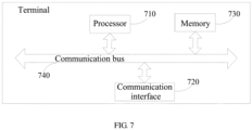
- the terminal may include a processor 710, a communication interface 720, a memory 730, and a communication bus 740.
- the processor 710, the communication interface 720, and the memory 730 communicate with each other through the communication bus 740.
- the processor 710 may invoke computer programs stored on the memory 730 and executable on the processor 710 to perform the following steps:
- the processor when executing the programs, further implements the following step: determining whether to transmit the one or more second target uplink channels.
- determining whether to transmit the one or more first target uplink channels includes: when a symbol set in which the one or more first target uplink channels is located does not include a first unavailable symbol, determining to transmit the one or more first target uplink channels; and
- determining whether to transmit the one or more second target uplink channels includes: when the symbol set in which the one or more second target uplink channels is located does not include a third unavailable symbol, determining to transmit the one or more second target uplink channels.
- the third unavailable symbol includes at least one of the following symbols: a DL symbol configured by a higher layer signaling, a FL symbol configured by a higher layer signaling, a symbol scheduled by DCI for downlink transmission, a symbol indicated as DL or FL by indication information in DCI for indicating a structure of a time unit, a symbol for a GP, a symbol for a SSB transmission, an unavailable symbol preconfigured by signaling or a symbol within BWP switching time.
- the plurality of uplink channels include at least one channel configured by the higher layer signaling for transmission.
- determining whether to transmit the one or more first target uplink channels includes: when each of the one or more first target uplink channels is a channel configured by the higher layer signaling for transmission, determining to transmit the first target uplink channels; and determining, from the plurality of uplink channels, the candidate uplink channels which could be transmitted includes: determining the candidate uplink channels which could be transmitted from the channels configured by the higher layer signaling for transmission.
- determining whether to transmit the one or more second target uplink channel includes: when each of the one or more second target uplink channels is a channel configured by the higher layer signaling for transmission, determining to transmit the one or more second target uplink channels.
- the channel configured by the higher layer signaling for transmission includes at least one of the following channels: a physical uplink shared channel (PUSCH) without a corresponding physical downlink control channel (PDCCH), and a PUCCH transmission using a physical uplink control channel (PUCCH) resource corresponding to the semi-persistent scheduling (SPS), a PUCCH transmission using a PUCCH resource corresponding to channel state information (CSI) or a PUCCH transmission using a PUCCH resource corresponding to a scheduling request (SR).
- PUSCH physical uplink shared channel
- PUCCH physical uplink control channel
- SPS semi-persistent scheduling
- CSI channel state information
- SR scheduling request
- the above terminal can implement all steps of the method on the terminal side and achieve the same beneficial effects, and the same steps of the method and the same beneficial effects in the terminal as the terminal side method embodiments will not be repeated here.
- the logic instructions in the memory 730 described above may be implemented in the form of a software functional unit and may be stored in a computer readable storage medium while being sold or used as a separate product. Therefore, the embodiments of the present application provide a software product, which is stored in a storage medium and includes several instructions to cause a computer device (for example, a personal computer, server, or network device, etc.) to perform all or part of steps of the method described in various embodiments.
- the storage medium described above includes various media that can store program codes, such as U disk, mobile hard disk, read-only memory (ROM), random access memory (RAM), magnetic disk, or optical disk.
- the base station may include a processor 810, a communication interface 820, a memory 830, and a communication bus 840.
- the processor 810, the communication interface 820, and the memory 830 communicate with each other through the communication bus 840.
- the processor 810 may invoke computer programs stored on the memory 830 and executable on the processor 810 to perform the following steps:
- the processor when executing the program, further implements the following step: determining whether to receive the one or more second target uplink channels.
- the logic instructions in the memory 830 described above may be implemented in the form of a software functional unit and may be stored in a computer readable storage medium while being sold or used as a separate product. Therefore, the embodiments of the present application provide a software product, which is stored in a storage medium including several instructions to cause a computer device (for example, a personal computer, server, or network device, etc.) to perform all or part of steps of the method described in various embodiments.
- the storage medium described above includes various media that can store program codes such as U disk, mobile hard disk, read-only memory (ROM), random access memory (RAM), magnetic disk, or optical disk.
- the present application provides a non-transitory computer-readable storage medium having computer programs stored thereon.
- the computer programs when executed by the processor, cause the processor to perform the steps of the method mentioned above according to the embodiments.
- non-transitory computer-readable storage medium can implement all steps of the method of various embodiments and achieve the same beneficial effects, and the same steps of the method and the same beneficial effects in the on-transient computer-readable storage medium as the method embodiments will not be repeated here.
- the device embodiments described above are merely illustrative, wherein the units described as separate components may or may not be physically separated, and the components displayed as units may or may not be physical units, that is, may be located at the same place, or they can be distributed to multiple network units. Some or all of the modules may be selected according to actual needs to achieve the purpose of the solution of the present embodiment. Those of ordinary skill in the art can understand and implement the embodiments described above without paying creative labors.
- the various embodiments can be implemented by means of software and a necessary general hardware platform, and of course, by hardware. Therefore, the embodiments of the present application provide a software product, which is stored in a storage medium such as ROM/RAM, magnetic Discs, optical discs, etc., including several instructions to cause a computer device (for example, a personal computer, server, or network device, etc.) to perform various embodiments or a part of the methods described in various embodiments.
- a computer device for example, a personal computer, server, or network device, etc.
Landscapes
- Engineering & Computer Science (AREA)
- Signal Processing (AREA)
- Computer Networks & Wireless Communication (AREA)
- Mobile Radio Communication Systems (AREA)
Claims (15)
- Verfahren für eine Uplink-Kanalübertragung, die durch ein Endgerät durchgeführt wird, wobei das Verfahren für die Uplink-Kanalübertragung umfasst:wenn eine Vielzahl von Uplink-Kanälen sich in dem Zeitbereich überlappt,zuerst Verarbeiten (201) der Vielzahl von Uplink-Kanälen basierend auf einer Multiplexregel, um einen oder mehrere erste zu übertragende Ziel-Uplink-Kanäle zu bestimmen, und dann Bestimmen, ob der eine oder die mehreren ersten Ziel-Uplink-Kanäle zu übertragen sind; oderzuerst Bestimmen (301), aus der Vielzahl von Uplink-Kanälen, von Kandidaten-Uplink-Kanälen, die übertragen werden könnten, und dann Verarbeiten der Kandidaten-Uplink-Kanäle basierend auf einer Multiplexregel, um einen oder mehrere zweite zu übertragende Ziel-Uplink-Kanäle zu bestimmen;wobei das Bestimmen, ob der eine oder die mehreren ersten Ziel-Uplink-Kanäle zu übertragen sind, umfasst: wenn ein Symbolsatz, in dem der eine oder die mehreren ersten Ziel-Uplink-Kanäle sich befinden, kein erstes nicht verfügbares Symbol einschließt, Bestimmen, den einen oder die mehreren ersten Ziel-Uplink-Kanäle zu übertragen;wobei das Bestimmen, aus der Vielzahl von Uplink-Kanälen, der Kandidaten-Uplink-Kanäle, die übertragen werden könnten, umfasst: für jeden der Vielzahl von Uplink-Kanälen, Bestimmen des Uplink-Kanals als einen Kandidaten-Uplink-Kanal, wenn ein Symbolsatz, in dem der Uplink-Kanal sich befindet, kein zweites nicht verfügbares Symbol einschließt;wobei jedes des ersten nicht verfügbaren Symbols und des zweiten nicht verfügbaren Symbols mindestens eines der folgenden Symbole umfasst: ein Downlink-Symbol, DL-Symbol, das durch eine Signalisierung einer höheren Schicht konfiguriert ist, ein flexibles Symbol, FL-Symbol, das durch eine Signalisierung einer höheren Schicht konfiguriert ist, ein Symbol, das durch Downlink-Steuerinformationen, DCI, für die Downlink-Übertragung eingeplant ist, ein Symbol, das als DL oder FL durch Anzeigeinformationen in DCI zum Anzeigen einer Struktur einer Zeiteinheit angezeigt wird, ein Symbol für eine Schutzperiode, GP, ein Symbol für eine Übertragung eines Synchronisierungssignalblocks, SSB, ein nicht verfügbares Symbol, das durch Signalisierung vorkonfiguriert ist, oder ein Symbol innerhalb einer Umschaltzeit des Bandbreitenteils, BWP.
- Verfahren nach Anspruch 1, wobei nach dem Verarbeiten der Kandidaten-Uplink-Kanäle basierend auf der Multiplexregel, um den einen oder die mehreren zweiten zu übertragenden Ziel-Uplink-Kanäle zu bestimmen, das Verfahren für die Uplink-Kanalübertragung ferner umfasst:Bestimmen, ob der eine oder die mehreren zweiten Ziel-Uplink-Kanäle zu übertragen sind, oderwenn jeder der einen oder der mehreren zweiten Ziel-Uplink-Kanäle ein Kanal ist, der durch eine Signalisierung einer höheren Schicht für die Übertragung konfiguriert ist, Bestimmen, den einen oder die mehreren zweiten Ziel-Uplink-Kanäle zu übertragen,der Kanal, der durch die Signalisierung einer höheren Schicht für die Übertragung konfiguriert ist, mindestens einen der folgenden Kanäle umfasst:
einen gemeinsam genutzten physischen Uplink-Kanal, PUSCH, ohne einen entsprechenden physischen Downlink-Steuerkanal, PDCCH, eine Übertragung mit einem physischen Uplink-Steuerkanal, PUCCH, unter Verwendung einer PUCCH-Ressource entsprechend einer semipersistenten Planung, SPS, eine PUCCH-Übertragung unter Verwendung einer PUCCH-Ressource entsprechend Kanalzustandsinformationen, CSI, oder eine PUCCH-Übertragung unter Verwendung einer PUCCH-Ressource entsprechend einer Planungsanforderung, SR. - Verfahren nach Anspruch 1, wobeidas Bestimmen, ob der eine oder die mehreren ersten Ziel-Uplink-Kanäle zu übertragen sind, ferner umfasst: wenn jeder der einen oder der mehreren ersten Ziel-Uplink-Kanäle ein Kanal ist, der durch eine Signalisierung einer höheren Schicht für die Übertragung konfiguriert ist, Bestimmen, den einen oder die mehreren ersten Ziel-Uplink-Kanäle zu übertragen,der Kanal, der durch die Signalisierung einer höheren Schicht für die Übertragung konfiguriert ist, mindestens einen der folgenden Kanäle umfasst:
einen gemeinsam genutzten physischen Uplink-Kanal, PUSCH, ohne einen entsprechenden physischen Downlink-Steuerkanal, PDCCH, eine Übertragung mit einem physischen Uplink-Steuerkanal, PUCCH, unter Verwendung einer PUCCH-Ressource entsprechend einer semipersistenten Planung, SPS, eine PUCCH-Übertragung unter Verwendung einer PUCCH-Ressource entsprechend Kanalzustandsinformationen, CSI, oder eine PUCCH-Übertragung unter Verwendung einer PUCCH-Ressource entsprechend einer Planungsanforderung, SR;oder wobeidas Bestimmen, aus der Vielzahl von Uplink-Kanälen, der Kandidaten-Uplink-Kanäle, die übertragen werden könnten, ferner umfasst: Bestimmen, aus Kanälen, die durch die Signalisierung einer höheren Schicht für die Übertragung konfiguriert sind, der Kandidaten-Uplink-Kanäle, die übertragen werden könnten. - Verfahren nach Anspruch 2, wobei das Bestimmen, ob der eine oder die mehreren zweiten Ziel-Uplink-Kanäle zu übertragen sind, umfasst:wenn ein Symbolsatz, in dem der eine oder die mehreren zweiten Ziel-Uplink-Kanäle sich befinden, kein drittes nicht verfügbares Symbol einschließt, Bestimmen, den einen oder die mehreren zweiten Ziel-Uplink-Kanäle zu übertragen;wobei das dritte nicht verfügbare Symbol mindestens eines der folgenden Symbole umfasst:
ein DL-Symbol, das durch eine Signalisierung einer höheren Schicht konfiguriert ist, ein FL-Symbol, das durch eine Signalisierung einer höheren Schicht konfiguriert ist, ein Symbol, das durch DCI für die Downlink-Übertragung eingeplant ist, ein Symbol, das durch Anzeigeinformationen in DCI zum Anzeigen einer Struktur einer Zeiteinheit als DL oder FL angezeigt wird, ein Symbol für eine GP, ein Symbol für eine SSB-Übertragung, ein nicht verfügbares Symbol, das durch Signalisierung vorkonfiguriert ist, oder ein Symbol innerhalb der BWP-Umschaltzeit. - Verfahren für die Uplink-Kanalübertragung, das durch eine Basisstation durchgeführt wird, wobei das Verfahren für die Uplink-Kanalübertragung umfasst:wenn eine Vielzahl von Uplink-Kanälen sich in dem Zeitbereich überlappt,zuerst Verarbeiten (401) der Vielzahl von Uplink-Kanälen basierend auf einer Multiplexregel, um einen oder mehrere erste zu empfangende Ziel-Uplink-Kanäle zu bestimmen, und dann Bestimmen, ob der eine oder die mehreren ersten Ziel-Uplink-Kanäle zu empfangen sind; oderzuerst Bestimmen (501), aus der Vielzahl von Uplink-Kanälen, der Kandidaten-Uplink-Kanäle, die empfangen werden könnten, und dann Verarbeiten der Kandidaten-Uplink-Kanäle basierend auf einer Multiplexregel, um einen oder mehrere zweite zu empfangende Ziel-Uplink-Kanäle zu bestimmen;wobei das Bestimmen, ob der eine oder die mehreren ersten Ziel-Uplink-Kanäle zu empfangen sind, umfasst: wenn ein Symbolsatz, in dem die ersten Ziel-Uplink-Kanäle sich befinden, kein erstes nicht verfügbares Symbol einschließt, Bestimmen, den einen oder die mehreren ersten Ziel-Uplink-Kanäle zu empfangen;wobei das Bestimmen, aus der Vielzahl von Uplink-Kanälen, der Kandidaten-Uplink-Kanäle, die empfangen werden könnten, umfasst: für jeden der Vielzahl von Uplink-Kanälen, Bestimmen des Uplink-Kanals als einen Kandidaten-Uplink-Kanal, wenn ein Symbolsatz, in dem der Uplink-Kanal sich befindet, kein zweites nicht verfügbares Symbol einschließt;wobei jedes des ersten nicht verfügbaren Symbols und des zweiten nicht verfügbaren Symbols mindestens eines der folgenden Symbole umfasst: ein Downlink-Symbol, DL-Symbol, das durch eine Signalisierung einer höheren Schicht konfiguriert ist, ein flexibles Symbol, FL-Symbol, das durch eine Signalisierung der höheren Schicht konfiguriert ist, ein Symbol, das durch Downlink-Steuerinformationen, DCI, für die Downlink-Übertragung eingeplant ist, ein Symbol, das als DL oder FL durch Anzeigeinformationen in DCI zum Anzeigen einer Struktur einer Zeiteinheit angezeigt wird, ein Symbol für eine Schutzperiode, GP, ein Symbol für eine Übertragung eines Synchronisierungssignalblocks, SSB, ein nicht verfügbares Symbol, das durch Signalisierung vorkonfiguriert ist, oder ein Symbol innerhalb einer Umschaltzeit des Bandbreitenteils, BWP.
- Verfahren nach Anspruch 5, wobei nach dem Verarbeiten der Kandidaten-Uplink-Kanäle basierend auf der Multiplexregel, um den einen oder die mehreren zu empfangenden zweiten Ziel-Uplink-Kanäle zu bestimmen, das Verfahren für die Uplink-Kanalübertragung ferner umfasst:Bestimmen, ob der eine oder die mehreren zweiten Ziel-Uplink-Kanäle zu empfangen sind, oderwenn jeder der einen oder der mehreren zweiten Ziel-Uplink-Kanäle ein Kanal ist, der durch eine Signalisierung einer höheren Schicht für die Übertragung konfiguriert ist, Bestimmen, den einen oder die mehreren zweiten Ziel-Uplink-Kanäle zu empfangen,der Kanal, der durch die Signalisierung einer höheren Schicht für die Übertragung konfiguriert ist, mindestens einen der folgenden Kanäle umfasst:
einen gemeinsam genutzten physischen Uplink-Kanal, PUSCH, ohne einen entsprechenden physischen Downlink-Steuerkanal, PDCCH, eine Übertragung mit einem physischen Uplink-Steuerkanal, PUCCH, unter Verwendung einer PUCCH-Ressource entsprechend einer semipersistenten Planung, SPS, eine PUCCH-Übertragung unter Verwendung einer PUCCH-Ressource entsprechend Kanalzustandsinformationen, CSI, oder eine PUCCH-Übertragung unter Verwendung einer PUCCH-Ressource entsprechend einer Planungsanforderung, SR. - Verfahren nach Anspruch 5, wobei:das Bestimmen, ob der eine oder die mehreren ersten Ziel-Uplink-Kanäle zu empfangen sind, ferner umfasst: wenn jeder der einen oder der mehreren ersten Ziel-Uplink-Kanäle ein Kanal ist, der durch eine Signalisierung einer höheren Schicht für die Übertragung konfiguriert ist, Bestimmen, den einen oder die mehreren ersten Ziel-Uplink-Kanäle zu empfangen,der Kanal, der durch die Signalisierung einer höheren Schicht für die Übertragung konfiguriert ist, mindestens einen der folgenden Kanäle umfasst:
einen gemeinsam genutzten physischen Uplink-Kanal, PUSCH, ohne einen entsprechenden physischen Downlink-Steuerkanal, PDCCH, eine Übertragung mit einem physischen Uplink-Steuerkanal, PUCCH, unter Verwendung einer PUCCH-Ressource entsprechend einer semipersistenten Planung, SPS, eine PUCCH-Übertragung unter Verwendung einer PUCCH-Ressource entsprechend Kanalzustandsinformationen, CSI, oder eine PUCCH-Übertragung unter Verwendung einer PUCCH-Ressource entsprechend einer Planungsanforderung, SR;oder wobeidas Bestimmen, aus der Vielzahl von Uplink-Kanälen, der Kandidaten-Uplink-Kanäle, die empfangen werden könnten, ferner umfasst: Bestimmen, aus Kanälen, die durch die Signalisierung der höheren Schicht für die Übertragung konfiguriert sind, der Kandidaten-Uplink-Kanäle, die empfangen werden könnten. - Verfahren nach Anspruch 6, wobei das Bestimmen, ob der eine oder die mehreren zweiten Ziel-Uplink-Kanäle zu empfangen sind, umfasst:wenn ein Symbolsatz, in dem der eine oder die mehreren zweiten Ziel-Uplink-Kanäle sich befinden, kein drittes nicht verfügbares Symbol einschließt, Bestimmen, den einen oder die mehreren zweiten Ziel-Uplink-Kanäle zu empfangen;wobei das dritte nicht verfügbare Symbol mindestens eines der folgenden Symbole umfasst:
ein DL-Symbol, das durch eine Signalisierung einer höheren Schicht konfiguriert ist, ein FL-Symbol, das durch eine Signalisierung einer höheren Schicht konfiguriert ist, ein Symbol, das durch DCI für die Downlink-Übertragung eingeplant ist, ein Symbol, das durch Anzeigeinformationen in DCI zum Anzeigen einer Struktur einer Zeiteinheit als DL oder FL angezeigt wird, ein Symbol für eine GP, ein Symbol für eine SSB-Übertragung, ein nicht verfügbares Symbol, das durch Signalisierung vorkonfiguriert ist, oder ein Symbol innerhalb der BWP-Umschaltzeit. - Endgerät, umfassend:einen Prozessor (710) undeinen Speicher (730), der ein Programm speichert, das durch den Prozessor (710) ausführbar ist, wobei das Programm, wenn es durch den Prozessor (710) ausgeführt wird, bewirkt, dass der Prozessor (710) die folgenden Schritte durchführt:wenn eine Vielzahl von Uplink-Kanälen sich in dem Zeitbereich überlappt,zuerst Verarbeiten der Vielzahl von Uplink-Kanälen basierend auf einer Multiplexregel, um einen oder mehrere erste zu übertragende Ziel-Uplink-Kanäle zu bestimmen, und dann Bestimmen, ob der eine oder die mehreren ersten Ziel-Uplink-Kanäle zu übertragen sind; oderzuerst Bestimmen, aus der Vielzahl von Uplink-Kanälen, von Kandidaten-Uplink-Kanälen, die übertragen werden könnten, und dann Verarbeiten der Kandidaten-Uplink-Kanäle basierend auf einer Multiplexregel, um einen oder mehrere zweite zu übertragende Ziel-Uplink-Kanäle zu bestimmenwobei das Bestimmen, ob die ersten Ziel-Uplink-Kanäle zu übertragen sind, umfasst: wenn ein Symbolsatz, in dem der eine oder die mehreren ersten Ziel-Uplink-Kanäle sich befinden, kein erstes nicht verfügbares Symbol einschließt, Bestimmen, die ersten Ziel-Uplink-Kanäle zu übertragen;wobei das Bestimmen, aus der Vielzahl von Uplink-Kanälen, der Kandidaten-Uplink-Kanäle, die übertragen werden könnten, umfasst: für jeden der Vielzahl von Uplink-Kanälen, Bestimmen des Uplink-Kanals als einen Kandidaten-Uplink-Kanal, wenn ein Symbolsatz, in dem die Uplink-Kanalübertragung sich befindet, kein zweites nicht verfügbares Symbol einschließt;wobei jedes des ersten nicht verfügbaren Symbols und des zweiten nicht verfügbaren Symbols mindestens eines der folgenden Symbole umfasst: ein Downlink-Symbol, DL-Symbol, das durch eine Signalisierung einer höheren Schicht konfiguriert ist, ein flexibles Symbol, FL-Symbol, das durch eine Signalisierung der höheren Schicht konfiguriert ist, ein Symbol, das durch Downlink-Steuerinformationen, DCI, für die Downlink-Übertragung eingeplant ist, ein Symbol, das als DL oder FL durch Anzeigeinformationen in DCI zum Anzeigen einer Struktur einer Zeiteinheit angezeigt wird, ein Symbol für eine Schutzperiode, GP, ein Symbol für eine Übertragung eines Synchronisierungssignalblocks, SSB, ein nicht verfügbares Symbol, das durch Signalisierung vorkonfiguriert ist, oder ein Symbol innerhalb einer Umschaltzeit des Bandbreitenteils, BWP.
- Endgerät nach Anspruch 9, wobei nach dem Verarbeiten der Kandidaten-Uplink-Kanäle basierend auf der Multiplexregel, um den einen oder die mehreren zweiten zu übertragenden Ziel-Uplink-Kanäle zu bestimmen, das Programm, wenn es durch den Prozessor ausgeführt wird, bewirkt, dass der Prozessor den folgenden Schritt durchführt:Bestimmen, ob der eine oder die mehreren zweiten Ziel-Uplink-Kanäle zu übertragen sind, oderwenn jeder der einen oder der mehreren zweiten Ziel-Uplink-Kanäle ein Kanal ist, der durch eine Signalisierung einer höheren Schicht für die Übertragung konfiguriert ist, Bestimmen, den einen oder die mehreren zweiten Ziel-Uplink-Kanäle zu übertragen,der Kanal, der durch die Signalisierung einer höheren Schicht für die Übertragung konfiguriert ist, mindestens einen der folgenden Kanäle umfasst:
einen gemeinsam genutzten physischen Uplink-Kanal, PUSCH, ohne einen entsprechenden physischen Downlink-Steuerkanal, PDCCH, eine Übertragung mit einem physischen Uplink-Steuerkanal, PUCCH, unter Verwendung einer PUCCH-Ressource entsprechend einer semipersistenten Planung, SPS, eine PUCCH-Übertragung unter Verwendung einer PUCCH-Ressource entsprechend Kanalzustandsinformationen, CSI, oder eine PUCCH-Übertragung unter Verwendung einer PUCCH-Ressource entsprechend einer Planungsanforderung, SR. - Endgerät nach Anspruch 9, wobeidas Bestimmen, ob die ersten Ziel-Uplink-Kanäle zu übertragen sind, ferner umfasst: wenn jeder der einen oder der mehreren ersten Ziel-Uplink-Kanäle ein Kanal ist, der durch eine Signalisierung einer höheren Schicht für die Übertragung konfiguriert ist, Bestimmen, den einen oder die mehreren ersten Ziel-Uplink-Kanäle zu übertragen,der Kanal, der durch die Signalisierung einer höheren Schicht für die Übertragung konfiguriert ist, mindestens einen der folgenden Kanäle umfasst:
einen gemeinsam genutzten physischen Uplink-Kanal, PUSCH, ohne einen entsprechenden physischen Downlink-Steuerkanal, PDCCH, eine Übertragung mit einem physischen Uplink-Steuerkanal, PUCCH, unter Verwendung einer PUCCH-Ressource entsprechend einer semipersistenten Planung, SPS, eine PUCCH-Übertragung unter Verwendung einer PUCCH-Ressource entsprechend Kanalzustandsinformationen, CSI, oder eine PUCCH-Übertragung unter Verwendung einer PUCCH-Ressource entsprechend einer Planungsanforderung, SR;oder wobeidas Bestimmen, aus der Vielzahl von Uplink-Kanälen, der Kandidaten-Uplink-Kanäle, die übertragen werden könnten, ferner umfasst: Bestimmen, aus Kanälen, die durch die Signalisierung der höheren Schicht für die Übertragung konfiguriert sind, der Kandidaten-Uplink-Kanäle, die übertragen werden könnten. - Endgerät nach Anspruch 10, wobei das Bestimmen, ob der eine oder die mehreren zweiten Ziel-Uplink-Kanäle zu übertragen sind, umfasst:wenn ein Symbolsatz, in dem der eine oder die mehreren zweiten Ziel-Uplink-Kanäle sich befinden, kein drittes nicht verfügbares Symbol einschließt, Bestimmen, den einen oder die mehreren zweiten Ziel-Uplink-Kanäle zu übertragen;wobei das dritte nicht verfügbare Symbol mindestens eines der folgenden Symbole umfasst:
ein DL-Symbol, das durch eine Signalisierung einer höheren Schicht konfiguriert ist, ein FL-Symbol, das durch eine Signalisierung einer höheren Schicht konfiguriert ist, ein Symbol, das durch DCI für die Downlink-Übertragung eingeplant ist, ein Symbol, das durch Anzeigeinformationen in DCI zum Anzeigen einer Struktur einer Zeiteinheit als DL oder FL angezeigt wird, ein Symbol für eine GP, ein Symbol für eine SSB-Übertragung, ein nicht verfügbares Symbol, das durch Signalisierung vorkonfiguriert ist, oder ein Symbol innerhalb der BWP-Umschaltzeit. - Basisstation, umfassend:einen Prozessor (810) undeinen Speicher (830), der ein durch den Prozessor (810) ausführbares Programm speichert, wobei das Programm, wenn es durch den Prozessor (810) ausgeführt wird, bewirkt, dass der Prozessor (810) die folgenden Schritte durchführt:wenn eine Vielzahl von Uplink-Kanälen sich in dem Zeitbereich überlappt,zuerst Verarbeiten der Vielzahl von Uplink-Kanälen basierend auf einer Multiplexregel, um einen oder mehrere erste zu empfangende Ziel-Uplink-Kanäle zu bestimmen, und dann Bestimmen, ob der eine oder die mehreren ersten Ziel-Uplink-Kanäle zu empfangen sind; oderzuerst Bestimmen, aus der Vielzahl von Uplink-Kanälen, der Kandidaten-Uplink-Kanäle, die empfangen werden könnten, und dann Verarbeiten der Kandidaten-Uplink-Kanäle basierend auf einer Multiplexregel, um einen oder mehrere zweite zu empfangende Ziel-Uplink-Kanäle zu bestimmenwobei das Bestimmen, ob der eine oder die mehreren ersten Ziel-Uplink-Kanäle zu empfangen sind, umfasst: wenn ein Symbolsatz, in dem der eine oder die mehreren ersten Ziel-Uplink-Kanäle sich befinden, kein erstes nicht verfügbares Symbol einschließt, Bestimmen, den einen oder die mehreren ersten Ziel-Uplink-Kanäle zu empfangen;wobei das Bestimmen, aus der Vielzahl von Uplink-Kanälen, der Kandidaten-Uplink-Kanäle, die empfangen werden könnten, umfasst: für jeden der Vielzahl von Uplink-Kanälen, Bestimmen des Uplink-Kanals als einen Kandidaten-Uplink-Kanal, wenn ein Symbolsatz, in dem der Uplink-Kanal sich befindet, kein zweites nicht verfügbares Symbol einschließt;wobei jedes des ersten nicht verfügbaren Symbols und des zweiten nicht verfügbaren Symbols mindestens eines der folgenden Symbole umfasst: ein Downlink-Symbol, DL-Symbol, das durch eine Signalisierung einer höheren Schicht konfiguriert ist, ein flexibles Symbol, FL-Symbol, das durch eine Signalisierung der höheren Schicht konfiguriert ist, ein Symbol, das durch Downlink-Steuerinformationen, DCI, für die Downlink-Übertragung eingeplant ist, ein Symbol, das als DL oder FL durch Anzeigeinformationen in DCI zum Anzeigen einer Struktur einer Zeiteinheit angezeigt wird, ein Symbol für eine Schutzperiode, GP, ein Symbol für eine Übertragung eines Synchronisierungssignalblocks, SSB, ein nicht verfügbares Symbol, das durch Signalisierung vorkonfiguriert ist, oder ein Symbol innerhalb einer Umschaltzeit des Bandbreitenteils, BWP.
- Basisstation nach Anspruch 13, wobei nach dem Verarbeiten der Kandidaten-Uplink-Kanäle basierend auf der Multiplexregel, um den einen oder die mehreren zweiten zu empfangenden Ziel-Uplink-Kanäle zu bestimmen, das Programm, wenn es durch den Prozessor ausgeführt wird, bewirkt, dass der Prozessor den folgenden Schritt durchführt:
Bestimmen, ob der eine oder die mehreren zweiten Ziel-Uplink-Kanäle zu empfangen sind, wobei das Bestimmen, ob der eine oder die mehreren zweiten Ziel-Uplink-Kanäle zu empfangen sind, umfasst:wenn ein Symbolsatz, in dem der eine oder die mehreren zweiten Ziel-Uplink-Kanäle sich befinden, kein drittes nicht verfügbares Symbol einschließt, Bestimmen, den einen oder die mehreren zweiten Ziel-Uplink-Kanäle zu empfangen;wobei das dritte nicht verfügbare Symbol mindestens eines der folgenden Symbole umfasst:ein DL-Symbol, das durch eine Signalisierung einer höheren Schicht konfiguriert ist, ein FL-Symbol, das durch eine Signalisierung einer höheren Schicht konfiguriert ist, ein Symbol, das durch DCI für die Downlink-Übertragung eingeplant ist, ein Symbol, das durch Anzeigeinformationen in DCI zum Anzeigen einer Struktur einer Zeiteinheit als DL oder FL angezeigt wird, ein Symbol für eine GP, ein Symbol für eine SSB-Übertragung, ein nicht verfügbares Symbol, das durch Signalisierung vorkonfiguriert ist, oder ein Symbol innerhalb der BWP-Umschaltzeit; oderwenn jeder der einen oder der mehreren zweiten Ziel-Uplink-Kanäle ein Kanal ist, der durch eine Signalisierung einer höheren Schicht für die Übertragung konfiguriert ist, Bestimmen, den einen oder die mehreren zweiten Ziel-Uplink-Kanäle zu empfangen,der Kanal, der durch die Signalisierung einer höheren Schicht für die Übertragung konfiguriert ist, mindestens einen der folgenden Kanäle umfasst:
einen gemeinsam genutzten physischen Uplink-Kanal, PUSCH, ohne einen entsprechenden physischen Downlink-Steuerkanal, PDCCH, eine Übertragung mit einem physischen Uplink-Steuerkanal, PUCCH, unter Verwendung einer PUCCH-Ressource entsprechend einer semipersistenten Planung, SPS, eine PUCCH-Übertragung unter Verwendung einer PUCCH-Ressource entsprechend Kanalzustandsinformationen, CSI, oder eine PUCCH-Übertragung unter Verwendung einer PUCCH-Ressource entsprechend einer Planungsanforderung, SR. - Basisstation nach Anspruch 13, wobeidas Bestimmen, ob der eine oder die mehreren ersten Ziel-Uplink-Kanäle zu empfangen sind, ferner umfasst: wenn jeder der einen oder der mehreren ersten Ziel-Uplink-Kanäle ein Kanal ist, der durch eine Signalisierung einer höheren Schicht für die Übertragung konfiguriert ist, Bestimmen, den einen oder die mehreren ersten Ziel-Uplink-Kanäle zu empfangen,der Kanal, der durch die Signalisierung einer höheren Schicht für die Übertragung konfiguriert ist, mindestens einen der folgenden Kanäle umfasst:
einen gemeinsam genutzten physischen Uplink-Kanal, PUSCH, ohne einen entsprechenden physischen Downlink-Steuerkanal, PDCCH, eine Übertragung mit einem physischen Uplink-Steuerkanal, PUCCH, unter Verwendung einer PUCCH-Ressource entsprechend einer semipersistenten Planung, SPS, eine PUCCH-Übertragung unter Verwendung einer PUCCH-Ressource entsprechend Kanalzustandsinformationen, CSI, oder eine PUCCH-Übertragung unter Verwendung einer PUCCH-Ressource entsprechend einer Planungsanforderung, SR;oder wobeidas Bestimmen, aus der Vielzahl von Uplink-Kanälen, der Kandidaten-Uplink-Kanäle, die empfangen werden könnten, ferner umfasst: Bestimmen, aus Kanälen, die durch die Signalisierung der höheren Schicht für die Übertragung konfiguriert sind, der Kandidaten-Uplink-Kanäle, die empfangen werden könnten.
Priority Applications (1)
| Application Number | Priority Date | Filing Date | Title |
|---|---|---|---|
| EP25154273.4A EP4539574A3 (de) | 2019-12-06 | 2020-09-15 | Uplink-kanalübertragungsverfahren, endgerät und basisstation |
Applications Claiming Priority (2)
| Application Number | Priority Date | Filing Date | Title |
|---|---|---|---|
| CN201911243473.3A CN112929137B (zh) | 2019-12-06 | 2019-12-06 | 一种上行信道传输方法、终端及基站 |
| PCT/CN2020/113416 WO2021109653A1 (zh) | 2019-12-06 | 2020-09-15 | 一种上行信道传输方法、终端及基站 |
Related Child Applications (1)
| Application Number | Title | Priority Date | Filing Date |
|---|---|---|---|
| EP25154273.4A Division EP4539574A3 (de) | 2019-12-06 | 2020-09-15 | Uplink-kanalübertragungsverfahren, endgerät und basisstation |
Publications (3)
| Publication Number | Publication Date |
|---|---|
| EP4072054A1 EP4072054A1 (de) | 2022-10-12 |
| EP4072054A4 EP4072054A4 (de) | 2023-01-11 |
| EP4072054B1 true EP4072054B1 (de) | 2025-01-29 |
Family
ID=76161695
Family Applications (2)
| Application Number | Title | Priority Date | Filing Date |
|---|---|---|---|
| EP20897577.1A Active EP4072054B1 (de) | 2019-12-06 | 2020-09-15 | Verfahren zur uplink-kanal-übertragung, endgerät und basisstation |
| EP25154273.4A Pending EP4539574A3 (de) | 2019-12-06 | 2020-09-15 | Uplink-kanalübertragungsverfahren, endgerät und basisstation |
Family Applications After (1)
| Application Number | Title | Priority Date | Filing Date |
|---|---|---|---|
| EP25154273.4A Pending EP4539574A3 (de) | 2019-12-06 | 2020-09-15 | Uplink-kanalübertragungsverfahren, endgerät und basisstation |
Country Status (5)
| Country | Link |
|---|---|
| US (1) | US12348453B2 (de) |
| EP (2) | EP4072054B1 (de) |
| CN (2) | CN112929137B (de) |
| ES (1) | ES3021558T3 (de) |
| WO (1) | WO2021109653A1 (de) |
Families Citing this family (6)
| Publication number | Priority date | Publication date | Assignee | Title |
|---|---|---|---|---|
| WO2021221431A1 (ko) * | 2020-04-27 | 2021-11-04 | 엘지전자 주식회사 | 하향링크 채널을 수신하는 방법, 사용자기기, 프로세싱 장치, 저장 매체 및 컴퓨터 프로그램, 그리고 하향링크 채널을 전송하는 방법 및 기지국 |
| DE112021005513T5 (de) * | 2020-10-20 | 2023-08-17 | Sony Group Corporation | Kommunikationsvorrichtung, Infrastrukturausrüstung und Verfahren |
| US11765765B2 (en) * | 2021-04-30 | 2023-09-19 | Qualcomm Incorporated | Multiplexing techniques for multiple uplink component carriers |
| CN115701189B (zh) * | 2021-07-30 | 2026-03-17 | 维沃移动通信有限公司 | 上行传输方法、装置及终端 |
| CN117956590A (zh) * | 2023-11-13 | 2024-04-30 | 中兴通讯股份有限公司 | 信号传输方法、装置及存储介质 |
| CN120786682A (zh) * | 2024-07-23 | 2025-10-14 | 中兴通讯股份有限公司 | 一种信道传输方法、装置、存储介质及程序产品 |
Citations (1)
| Publication number | Priority date | Publication date | Assignee | Title |
|---|---|---|---|---|
| US20190261391A1 (en) * | 2018-01-22 | 2019-08-22 | Intel Corporation | Handling overlapping of pucch and pusch for new radio systems |
Family Cites Families (34)
| Publication number | Priority date | Publication date | Assignee | Title |
|---|---|---|---|---|
| CN102098086B (zh) * | 2010-12-30 | 2016-03-02 | 中兴通讯股份有限公司 | 数据发送方法及装置 |
| US10057893B2 (en) * | 2012-05-10 | 2018-08-21 | Qualcomm Incorporated | Interaction of sounding reference signals with uplink channels for coordinated multi-point operations |
| WO2014168336A1 (ko) * | 2013-04-11 | 2014-10-16 | 엘지전자 주식회사 | 상향링크 신호 전송 방법 및 사용자기기 |
| US9844072B2 (en) * | 2014-09-26 | 2017-12-12 | Qualcomm Incorporated | Ultra-low latency LTE uplink frame structure |
| US20170135090A1 (en) * | 2015-11-11 | 2017-05-11 | Sharp Laboratories Of America, Inc. | Systems and methods for uplink control information reporting with license-assisted access (laa) uplink transmissions |
| CN114499806B (zh) * | 2016-03-25 | 2024-04-30 | 韦勒斯标准与技术协会公司 | 在无线通信系统中对非授权带的上行链路信道接入的方法及其装置 |
| KR20170112633A (ko) * | 2016-04-01 | 2017-10-12 | 남정길 | 비면허 스펙트럼에서 상향링크 제어 채널 전송과 사운딩 참조신호 전송을 멀티플렉싱하는 방법 및 장치 |
| US10333670B2 (en) * | 2016-05-06 | 2019-06-25 | Qualcomm Incorporated | Sounding reference signals with collisions in asymmetric carrier aggregation |
| EP3681079B1 (de) | 2017-09-08 | 2022-12-07 | Wilus Institute of Standards and Technology Inc. | Datenübertragungsverfahren und empfangsverfahren für ein drahtloses kommunikationssystem und vorrichtung damit |
| CN116600389B (zh) | 2017-09-11 | 2026-04-14 | 韦勒斯标准与技术协会公司 | 无线通信系统中的上行链路传输和下行链路接收的方法、设备和系统 |
| CN109600844B (zh) * | 2017-09-30 | 2021-08-24 | 中兴通讯股份有限公司 | 确定时频资源的方法及装置 |
| WO2019096059A1 (en) * | 2017-11-15 | 2019-05-23 | Telefonaktiebolaget Lm Ericsson (Publ) | Corresponding configuration for simultaneous physical uplink control channel pucch and physical uplink shared channel pusch transmission |
| CN109905207B (zh) * | 2017-12-08 | 2021-07-27 | 大唐移动通信设备有限公司 | 物理上行共享信道的传输方法、接收方法、终端及基站 |
| CN110035550B (zh) * | 2018-01-12 | 2021-08-13 | 华为技术有限公司 | 上行控制信息传输方法和通信装置 |
| US10708866B2 (en) * | 2018-04-05 | 2020-07-07 | Samsung Electronics Co., Ltd. | Signaling of control information in a communication system |
| CN110392432B (zh) * | 2018-04-20 | 2023-04-25 | 展讯通信(上海)有限公司 | 上行数据传输方法及装置 |
| CN116961864A (zh) * | 2018-05-18 | 2023-10-27 | 中兴通讯股份有限公司 | 信道配置方法及终端、存储介质、电子装置 |
| US11019682B2 (en) * | 2018-06-18 | 2021-05-25 | Apple Inc. | Methods to multiplex control information in accordance with multi-slot transmissions in new radio (NR) systems |
| US11064514B2 (en) * | 2018-08-10 | 2021-07-13 | Qualcomm Incorporated | Uplink collision handling for wireless communications |
| US11234252B2 (en) * | 2018-08-28 | 2022-01-25 | Qualcomm Incorporated | Uplink channel multiplexing and piggybacking |
| CN110932820B (zh) * | 2018-09-19 | 2022-01-14 | 华为技术有限公司 | 发送和接收上行控制信息的方法以及通信装置 |
| WO2020067762A1 (ko) * | 2018-09-27 | 2020-04-02 | 엘지전자 주식회사 | 스케줄링 요청 정보를 전송하는 방법 및 통신 장치 |
| CN114340008A (zh) * | 2019-01-11 | 2022-04-12 | 华为技术有限公司 | 上行控制信息复用的方法和装置 |
| WO2020204528A1 (ko) * | 2019-03-29 | 2020-10-08 | 엘지전자 주식회사 | 상향링크 전송을 수행하는 방법, 사용자기기, 장치, 저장 매체, 그리고 상향링크 수신을 수행하는 방법 및 기지국 |
| US11324024B2 (en) * | 2019-05-02 | 2022-05-03 | Qualcomm Incorporated | Uplink channel transmission for multiple transmit receive points (TRPs) |
| EP3942722B1 (de) * | 2019-05-02 | 2023-08-09 | Apple Inc. | Multiplexierung konfigurierter grant (cg)-übertragungen in new radio (nr)-systemen in einem unlizenzierten spektrum |
| EP3963780B1 (de) * | 2019-05-03 | 2024-08-28 | Telefonaktiebolaget LM Ericsson (publ) | Uplink-steuerungsinformationshandhabung für unterschlitze |
| KR102861571B1 (ko) * | 2019-05-24 | 2025-09-18 | 삼성전자 주식회사 | 무선 통신 시스템에서 제어 정보 전송 방법 및 장치 |
| WO2021060413A1 (en) * | 2019-09-25 | 2021-04-01 | Sharp Kabushiki Kaisha | User equipments, base stations and methods for a priority of uplink transmission(s) |
| WO2021062711A1 (zh) * | 2019-09-30 | 2021-04-08 | 华为技术有限公司 | 传输上行控制信息的方法和装置 |
| KR102865242B1 (ko) * | 2019-10-04 | 2025-09-25 | 삼성전자주식회사 | 무선 통신 시스템에서 신호를 송수신하는 방법 및 장치 |
| WO2021096960A1 (en) * | 2019-11-15 | 2021-05-20 | Qualcomm Incorporated | Determining priorities for overlapping channels |
| US11832254B2 (en) * | 2020-09-28 | 2023-11-28 | Samsung Electronics Co., Ltd. | Power headroom report types and triggering conditions |
| EP4211971A4 (de) * | 2020-10-14 | 2024-03-13 | Samsung Electronics Co., Ltd. | Endgerät, basisstation und davon durchgeführtes verfahren in einem drahtloskommunikationssystem |
-
2019
- 2019-12-06 CN CN201911243473.3A patent/CN112929137B/zh active Active
- 2019-12-06 CN CN202211426331.2A patent/CN115802506A/zh active Pending
-
2020
- 2020-09-15 EP EP20897577.1A patent/EP4072054B1/de active Active
- 2020-09-15 EP EP25154273.4A patent/EP4539574A3/de active Pending
- 2020-09-15 ES ES20897577T patent/ES3021558T3/es active Active
- 2020-09-15 US US17/780,022 patent/US12348453B2/en active Active
- 2020-09-15 WO PCT/CN2020/113416 patent/WO2021109653A1/zh not_active Ceased
Patent Citations (1)
| Publication number | Priority date | Publication date | Assignee | Title |
|---|---|---|---|---|
| US20190261391A1 (en) * | 2018-01-22 | 2019-08-22 | Intel Corporation | Handling overlapping of pucch and pusch for new radio systems |
Also Published As
| Publication number | Publication date |
|---|---|
| US12348453B2 (en) | 2025-07-01 |
| EP4539574A3 (de) | 2025-06-18 |
| CN115802506A (zh) | 2023-03-14 |
| CN112929137B (zh) | 2022-12-02 |
| ES3021558T3 (en) | 2025-05-27 |
| CN112929137A (zh) | 2021-06-08 |
| EP4072054A1 (de) | 2022-10-12 |
| WO2021109653A1 (zh) | 2021-06-10 |
| US20220407657A1 (en) | 2022-12-22 |
| EP4072054A4 (de) | 2023-01-11 |
| EP4539574A2 (de) | 2025-04-16 |
Similar Documents
| Publication | Publication Date | Title |
|---|---|---|
| EP4072054B1 (de) | Verfahren zur uplink-kanal-übertragung, endgerät und basisstation | |
| US11057872B2 (en) | Method and device for transmitting uplink control information | |
| EP3826343B1 (de) | Getrennte konfiguration von numerologieunterstützen ressourcen | |
| EP4057554A1 (de) | Verfahren und gerät zum verarbeiten von harq von sps pdsch und elektronische vorrichtung | |
| EP4013167B1 (de) | Uplink-steuerungsinformations-übertragungsverfahren und vorrichtung, endgerät und basisstation | |
| CN113170453A (zh) | 报告波束故障 | |
| EP3907916B1 (de) | Harq-ack/pucch übertragungen | |
| KR20200133256A (ko) | 업링크 전송, 통신방법, 장치 및 기지국, 단말기, 저장매체 | |
| EP4016902B1 (de) | Verarbeitungsverfahren für uplink-steuerungsinformationen (uci), endgerät und basisstation | |
| US12501422B2 (en) | UCI transmission method, device, terminal and base station | |
| RU2706857C1 (ru) | Способ радиосвязи, базовая станция и терминал | |
| JP7685673B2 (ja) | 伝送設定指示を決定する方法、装置、端末および記憶媒体 | |
| KR102161007B1 (ko) | 업링크 채널 송신 방법 및 장치 | |
| CN111953458B (zh) | 一种pucch资源确定方法和通信设备 | |
| CN111884770A (zh) | Harq-ack码本产生方法 | |
| US12507214B2 (en) | UCI combined transmission method, terminal, and network device | |
| CN108605314B (zh) | 一种上行数据传输方法及相关设备 | |
| CN112584498B (zh) | Uci的传输方法、装置、终端及基站 | |
| US12267818B2 (en) | Information sending method and apparatus, and information receiving apparatus | |
| EP4319396A1 (de) | Verfahren zur uci-übertragung auf pusch, endgerät und vorrichtung | |
| CN112825595B (zh) | 一种上行信道的传输、接收方法、终端及网络设备 | |
| CN114337950B (zh) | 传输处理方法、装置、终端及可读存储介质 | |
| US20240179713A1 (en) | Uplink control information transmission method and apparatus, and related device | |
| WO2025260754A1 (zh) | 上行控制信道资源配置及确定方法、通信设备及存储介质 | |
| WO2019165937A1 (zh) | 一种数据传输方法、装置及设备 |
Legal Events
| Date | Code | Title | Description |
|---|---|---|---|
| STAA | Information on the status of an ep patent application or granted ep patent |
Free format text: STATUS: THE INTERNATIONAL PUBLICATION HAS BEEN MADE |
|
| PUAI | Public reference made under article 153(3) epc to a published international application that has entered the european phase |
Free format text: ORIGINAL CODE: 0009012 |
|
| STAA | Information on the status of an ep patent application or granted ep patent |
Free format text: STATUS: REQUEST FOR EXAMINATION WAS MADE |
|
| 17P | Request for examination filed |
Effective date: 20220621 |
|
| AK | Designated contracting states |
Kind code of ref document: A1 Designated state(s): AL AT BE BG CH CY CZ DE DK EE ES FI FR GB GR HR HU IE IS IT LI LT LU LV MC MK MT NL NO PL PT RO RS SE SI SK SM TR |
|
| A4 | Supplementary search report drawn up and despatched |
Effective date: 20221212 |
|
| RIC1 | Information provided on ipc code assigned before grant |
Ipc: H04W 72/12 20090101ALI20221206BHEP Ipc: H04L 5/00 20060101AFI20221206BHEP |
|
| DAV | Request for validation of the european patent (deleted) | ||
| DAX | Request for extension of the european patent (deleted) | ||
| STAA | Information on the status of an ep patent application or granted ep patent |
Free format text: STATUS: EXAMINATION IS IN PROGRESS |
|
| 17Q | First examination report despatched |
Effective date: 20230814 |
|
| GRAP | Despatch of communication of intention to grant a patent |
Free format text: ORIGINAL CODE: EPIDOSNIGR1 |
|
| STAA | Information on the status of an ep patent application or granted ep patent |
Free format text: STATUS: GRANT OF PATENT IS INTENDED |
|
| INTG | Intention to grant announced |
Effective date: 20240722 |
|
| GRAJ | Information related to disapproval of communication of intention to grant by the applicant or resumption of examination proceedings by the epo deleted |
Free format text: ORIGINAL CODE: EPIDOSDIGR1 |
|
| STAA | Information on the status of an ep patent application or granted ep patent |
Free format text: STATUS: EXAMINATION IS IN PROGRESS |
|
| GRAP | Despatch of communication of intention to grant a patent |
Free format text: ORIGINAL CODE: EPIDOSNIGR1 |
|
| STAA | Information on the status of an ep patent application or granted ep patent |
Free format text: STATUS: GRANT OF PATENT IS INTENDED |
|
| GRAS | Grant fee paid |
Free format text: ORIGINAL CODE: EPIDOSNIGR3 |
|
| INTC | Intention to grant announced (deleted) | ||
| GRAA | (expected) grant |
Free format text: ORIGINAL CODE: 0009210 |
|
| STAA | Information on the status of an ep patent application or granted ep patent |
Free format text: STATUS: THE PATENT HAS BEEN GRANTED |
|
| INTG | Intention to grant announced |
Effective date: 20241127 |
|
| AK | Designated contracting states |
Kind code of ref document: B1 Designated state(s): AL AT BE BG CH CY CZ DE DK EE ES FI FR GB GR HR HU IE IS IT LI LT LU LV MC MK MT NL NO PL PT RO RS SE SI SK SM TR |
|
| REG | Reference to a national code |
Ref country code: GB Ref legal event code: FG4D |
|
| REG | Reference to a national code |
Ref country code: CH Ref legal event code: EP |
|
| REG | Reference to a national code |
Ref country code: DE Ref legal event code: R096 Ref document number: 602020045653 Country of ref document: DE |
|
| REG | Reference to a national code |
Ref country code: IE Ref legal event code: FG4D |
|
| REG | Reference to a national code |
Ref country code: ES Ref legal event code: FG2A Ref document number: 3021558 Country of ref document: ES Kind code of ref document: T3 Effective date: 20250527 |
|
| REG | Reference to a national code |
Ref country code: NL Ref legal event code: MP Effective date: 20250129 |
|
| PG25 | Lapsed in a contracting state [announced via postgrant information from national office to epo] |
Ref country code: NL Free format text: LAPSE BECAUSE OF FAILURE TO SUBMIT A TRANSLATION OF THE DESCRIPTION OR TO PAY THE FEE WITHIN THE PRESCRIBED TIME-LIMIT Effective date: 20250129 |
|
| PG25 | Lapsed in a contracting state [announced via postgrant information from national office to epo] |
Ref country code: RS Free format text: LAPSE BECAUSE OF FAILURE TO SUBMIT A TRANSLATION OF THE DESCRIPTION OR TO PAY THE FEE WITHIN THE PRESCRIBED TIME-LIMIT Effective date: 20250429 |
|
| PG25 | Lapsed in a contracting state [announced via postgrant information from national office to epo] |
Ref country code: FI Free format text: LAPSE BECAUSE OF FAILURE TO SUBMIT A TRANSLATION OF THE DESCRIPTION OR TO PAY THE FEE WITHIN THE PRESCRIBED TIME-LIMIT Effective date: 20250129 |
|
| PG25 | Lapsed in a contracting state [announced via postgrant information from national office to epo] |
Ref country code: PL Free format text: LAPSE BECAUSE OF FAILURE TO SUBMIT A TRANSLATION OF THE DESCRIPTION OR TO PAY THE FEE WITHIN THE PRESCRIBED TIME-LIMIT Effective date: 20250129 |
|
| REG | Reference to a national code |
Ref country code: LT Ref legal event code: MG9D |
|
| PG25 | Lapsed in a contracting state [announced via postgrant information from national office to epo] |
Ref country code: NO Free format text: LAPSE BECAUSE OF FAILURE TO SUBMIT A TRANSLATION OF THE DESCRIPTION OR TO PAY THE FEE WITHIN THE PRESCRIBED TIME-LIMIT Effective date: 20250429 Ref country code: IS Free format text: LAPSE BECAUSE OF FAILURE TO SUBMIT A TRANSLATION OF THE DESCRIPTION OR TO PAY THE FEE WITHIN THE PRESCRIBED TIME-LIMIT Effective date: 20250529 |
|
| REG | Reference to a national code |
Ref country code: AT Ref legal event code: MK05 Ref document number: 1764512 Country of ref document: AT Kind code of ref document: T Effective date: 20250129 |
|
| PG25 | Lapsed in a contracting state [announced via postgrant information from national office to epo] |
Ref country code: HR Free format text: LAPSE BECAUSE OF FAILURE TO SUBMIT A TRANSLATION OF THE DESCRIPTION OR TO PAY THE FEE WITHIN THE PRESCRIBED TIME-LIMIT Effective date: 20250129 |
|
| PG25 | Lapsed in a contracting state [announced via postgrant information from national office to epo] |
Ref country code: LV Free format text: LAPSE BECAUSE OF FAILURE TO SUBMIT A TRANSLATION OF THE DESCRIPTION OR TO PAY THE FEE WITHIN THE PRESCRIBED TIME-LIMIT Effective date: 20250129 Ref country code: PT Free format text: LAPSE BECAUSE OF FAILURE TO SUBMIT A TRANSLATION OF THE DESCRIPTION OR TO PAY THE FEE WITHIN THE PRESCRIBED TIME-LIMIT Effective date: 20250529 |
|
| PG25 | Lapsed in a contracting state [announced via postgrant information from national office to epo] |
Ref country code: GR Free format text: LAPSE BECAUSE OF FAILURE TO SUBMIT A TRANSLATION OF THE DESCRIPTION OR TO PAY THE FEE WITHIN THE PRESCRIBED TIME-LIMIT Effective date: 20250430 Ref country code: BG Free format text: LAPSE BECAUSE OF FAILURE TO SUBMIT A TRANSLATION OF THE DESCRIPTION OR TO PAY THE FEE WITHIN THE PRESCRIBED TIME-LIMIT Effective date: 20250129 |
|
| PG25 | Lapsed in a contracting state [announced via postgrant information from national office to epo] |
Ref country code: AT Free format text: LAPSE BECAUSE OF FAILURE TO SUBMIT A TRANSLATION OF THE DESCRIPTION OR TO PAY THE FEE WITHIN THE PRESCRIBED TIME-LIMIT Effective date: 20250129 |
|
| PG25 | Lapsed in a contracting state [announced via postgrant information from national office to epo] |
Ref country code: SE Free format text: LAPSE BECAUSE OF FAILURE TO SUBMIT A TRANSLATION OF THE DESCRIPTION OR TO PAY THE FEE WITHIN THE PRESCRIBED TIME-LIMIT Effective date: 20250129 |
|
| PG25 | Lapsed in a contracting state [announced via postgrant information from national office to epo] |
Ref country code: SM Free format text: LAPSE BECAUSE OF FAILURE TO SUBMIT A TRANSLATION OF THE DESCRIPTION OR TO PAY THE FEE WITHIN THE PRESCRIBED TIME-LIMIT Effective date: 20250129 |
|
| PG25 | Lapsed in a contracting state [announced via postgrant information from national office to epo] |
Ref country code: DK Free format text: LAPSE BECAUSE OF FAILURE TO SUBMIT A TRANSLATION OF THE DESCRIPTION OR TO PAY THE FEE WITHIN THE PRESCRIBED TIME-LIMIT Effective date: 20250129 |
|
| PGFP | Annual fee paid to national office [announced via postgrant information from national office to epo] |
Ref country code: DE Payment date: 20250919 Year of fee payment: 6 |
|
| PGFP | Annual fee paid to national office [announced via postgrant information from national office to epo] |
Ref country code: IT Payment date: 20250923 Year of fee payment: 6 |
|
| PGFP | Annual fee paid to national office [announced via postgrant information from national office to epo] |
Ref country code: GB Payment date: 20250919 Year of fee payment: 6 |
|
| PGFP | Annual fee paid to national office [announced via postgrant information from national office to epo] |
Ref country code: FR Payment date: 20250922 Year of fee payment: 6 |
|
| PG25 | Lapsed in a contracting state [announced via postgrant information from national office to epo] |
Ref country code: EE Free format text: LAPSE BECAUSE OF FAILURE TO SUBMIT A TRANSLATION OF THE DESCRIPTION OR TO PAY THE FEE WITHIN THE PRESCRIBED TIME-LIMIT Effective date: 20250129 Ref country code: CZ Free format text: LAPSE BECAUSE OF FAILURE TO SUBMIT A TRANSLATION OF THE DESCRIPTION OR TO PAY THE FEE WITHIN THE PRESCRIBED TIME-LIMIT Effective date: 20250129 |
|
| PG25 | Lapsed in a contracting state [announced via postgrant information from national office to epo] |
Ref country code: RO Free format text: LAPSE BECAUSE OF FAILURE TO SUBMIT A TRANSLATION OF THE DESCRIPTION OR TO PAY THE FEE WITHIN THE PRESCRIBED TIME-LIMIT Effective date: 20250129 |
|
| PG25 | Lapsed in a contracting state [announced via postgrant information from national office to epo] |
Ref country code: SK Free format text: LAPSE BECAUSE OF FAILURE TO SUBMIT A TRANSLATION OF THE DESCRIPTION OR TO PAY THE FEE WITHIN THE PRESCRIBED TIME-LIMIT Effective date: 20250129 |
|
| REG | Reference to a national code |
Ref country code: DE Ref legal event code: R097 Ref document number: 602020045653 Country of ref document: DE |
|
| PLBE | No opposition filed within time limit |
Free format text: ORIGINAL CODE: 0009261 |
|
| STAA | Information on the status of an ep patent application or granted ep patent |
Free format text: STATUS: NO OPPOSITION FILED WITHIN TIME LIMIT |
|
| 26N | No opposition filed |
Effective date: 20251030 |
|
| PGFP | Annual fee paid to national office [announced via postgrant information from national office to epo] |
Ref country code: ES Payment date: 20251030 Year of fee payment: 6 |