EP4072082A1 - Procédé de calcul de route et procédé de transmission de données - Google Patents
Procédé de calcul de route et procédé de transmission de données Download PDFInfo
- Publication number
- EP4072082A1 EP4072082A1 EP20908493.8A EP20908493A EP4072082A1 EP 4072082 A1 EP4072082 A1 EP 4072082A1 EP 20908493 A EP20908493 A EP 20908493A EP 4072082 A1 EP4072082 A1 EP 4072082A1
- Authority
- EP
- European Patent Office
- Prior art keywords
- route
- service
- delay
- data transmission
- transmission method
- Prior art date
- Legal status (The legal status is an assumption and is not a legal conclusion. Google has not performed a legal analysis and makes no representation as to the accuracy of the status listed.)
- Withdrawn
Links
Images






Classifications
-
- H—ELECTRICITY
- H04—ELECTRIC COMMUNICATION TECHNIQUE
- H04L—TRANSMISSION OF DIGITAL INFORMATION, e.g. TELEGRAPHIC COMMUNICATION
- H04L45/00—Routing or path finding of packets in data switching networks
- H04L45/12—Shortest path evaluation
- H04L45/121—Shortest path evaluation by minimising delays
-
- H—ELECTRICITY
- H04—ELECTRIC COMMUNICATION TECHNIQUE
- H04L—TRANSMISSION OF DIGITAL INFORMATION, e.g. TELEGRAPHIC COMMUNICATION
- H04L45/00—Routing or path finding of packets in data switching networks
- H04L45/02—Topology update or discovery
-
- H—ELECTRICITY
- H04—ELECTRIC COMMUNICATION TECHNIQUE
- H04L—TRANSMISSION OF DIGITAL INFORMATION, e.g. TELEGRAPHIC COMMUNICATION
- H04L45/00—Routing or path finding of packets in data switching networks
- H04L45/70—Routing based on monitoring results
-
- H—ELECTRICITY
- H04—ELECTRIC COMMUNICATION TECHNIQUE
- H04L—TRANSMISSION OF DIGITAL INFORMATION, e.g. TELEGRAPHIC COMMUNICATION
- H04L45/00—Routing or path finding of packets in data switching networks
- H04L45/76—Routing in software-defined topologies, e.g. routing between virtual machines
-
- H—ELECTRICITY
- H04—ELECTRIC COMMUNICATION TECHNIQUE
- H04L—TRANSMISSION OF DIGITAL INFORMATION, e.g. TELEGRAPHIC COMMUNICATION
- H04L47/00—Traffic control in data switching networks
- H04L47/10—Flow control; Congestion control
- H04L47/28—Flow control; Congestion control in relation to timing considerations
- H04L47/283—Flow control; Congestion control in relation to timing considerations in response to processing delays, e.g. caused by jitter or round trip time [RTT]
-
- H—ELECTRICITY
- H04—ELECTRIC COMMUNICATION TECHNIQUE
- H04W—WIRELESS COMMUNICATION NETWORKS
- H04W40/00—Communication routing or communication path finding
- H04W40/34—Modification of an existing route
Definitions
- the present application relates to the field of Software Defined Networks (SDNs), and in particular, to a route calculation method, a data transmission method, a service processing method, an SDN controller, a terminal, and a computer-readable storage medium.
- SDNs Software Defined Networks
- SDN is an open network architecture characterized by centralized control and network programmability, which allows network management personnel to perform management and operation on the entire network through software programming.
- the logical control function and the data forwarding function are separated, and a software-based network controller is used to realize the logical control function of the network.
- Existing SDN networks have the function of delay-based routing, i.e., during setup of a service, delays of routes between two nodes that implement the service may be automatically measured and sorted, so as to automatically select a route with an optimal delay.
- An object of the present application is to provide a route calculation method, a data transmission method, a service processing method, an SDN controller, a terminal, and a computer-readable storage medium.
- a route calculation method is provided, which is applied to an SDN controller.
- the method includes: monitoring a network resource status of a forwarding layer; and calculating a route with an optimal delay for a monitored predetermined service according to a changed network resource in response to a change in the network resource status of the forwarding layer.
- a data transmission method is provided, which is applied to an SDN controller.
- the data transmission method includes: determining a route with an optimal delay for a monitored predetermined service according to a predetermined algorithm, where the predetermined algorithm is the route calculation method provided in the present application; and migrating the monitored predetermined service to the route with the optimal delay in response to a predetermined condition being satisfied.
- a service processing method includes: generating a service creation instruction, where the service creation instruction includes delay monitoring configuration information or delay monitoring cancellation information, the delay monitoring configuration information is configured for controlling the SDN controller to execute the data transmission method provided in the present application, and the delay monitoring cancellation information is configured for controlling the SDN controller to stop execution of the data transmission method provided in the present application; and sending the service creation instruction to the SDN controller.
- a route calculation module includes: a monitoring unit, configured for monitoring a network resource status of a forwarding layer; and a calculation unit, configured for calculating a route with an optimal delay for a monitored predetermined service according to a changed network resource in response to a change in the network resource status of the forwarding layer.
- an SDN controller includes: a storage module, storing an executable program; and one or more processors, where the executable program, when executed by the one or more processors, causes the one or more processors to carry out the route calculation method provided in the present application or cause the one or more processors to carry out the data transmission method provided in the present application.
- a computer-readable storage medium storing an executable program which, when executed by a processor, causes the processor to carry out the route calculation method provided in the present application or the data transmission method provided in the present application.
- a terminal device includes: an instruction generation module, configured for generating a service creation instruction, where the service creation instruction includes delay monitoring configuration information or delay monitoring cancellation information, the delay monitoring configuration information is configured for controlling an SDN controller to execute the data transmission method provided in the present application, and the delay monitoring cancellation information is configured for controlling the SDN controller to stop execution of the data transmission method provided in the present application; and an instruction sending module, configured for sending the service creation instruction to the SDN controller.
- a computer-readable storage medium storing an executable program which, when executed by a processor, causes the processor to carry out the service processing method provided in the present application.
- the status of links of the forwarding layer always change.
- a method disclosed in the related technology is used to transmit data, it can only be ensured that the delay at the time of service setup is optimal.
- the network resource status of the forwarding layer is consistent with the status at the time of service setup, the route of the service at the time of service setup is optimal.
- a link state change occurs in the forwarding layer, it cannot be ensured whether the delay of the current route of the service is still optimal.
- a route calculation method a data transmission method, a service processing method, an SDN controller, a terminal, and a computer-readable storage medium are provided.
- the route calculation method can ensure that a service is still on a link with an optimal delay after the service starts.
- a route calculation method based on an SDN network is provided. As shown in FIG. 1 , the route calculation method includes steps S110 to S120.
- a network resource status of a forwarding layer is monitored.
- a route with an optimal delay is calculated for a monitored predetermined service according to a changed network resource in response to a change in the network resource status of the forwarding layer.
- the SDN network includes three parts: an application layer 100, an SDN controller 200, and a forwarding layer 300.
- the route calculation method provided in the present application is executed by the SDN controller 100.
- the SDN controller 200 communicates with the application layer 100 through a northbound interface.
- the SDN controller 200 communicates with the forwarding layer 300 through a southbound interface.
- the SDN network may further include a database 400.
- the network resource status of the forwarding layer is monitored at S 110, and once the network resource status of the forwarding layer 300 changes, link delays of links capable of executing the predetermined service in the forwarding layer 300 also change.
- the route with the optimal delay is recalculated for the monitored predetermined service at S120.
- the predetermined service may be manually switched to the route with the optimal delay by a user, or the predetermined service may be automatically switched to the route with the optimal delay by the SDN controller.
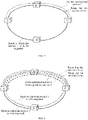
- a current route of the predetermined service i.e., a service 1 to be optimized
- a service route node A ⁇ node B ⁇ node C
- a route with the optimal delay is calculated for the predetermined service and determined as a service route (node A ⁇ node D ⁇ node C) (i.e., a route to which the service 1 is to be migrated in FIG. 3 ).
- the predetermined service may be manually switched from the route that the service 1 is on to the route to which the service 1 is to be migrated by the user, or may be automatically switched from the current route to the route to which the service 1 is to be migrated by the SDN controller.
- a service route 1 is the route with the optimal delay.
- the service route (node A ⁇ node D ⁇ node C) becomes the route with the optimal delay.
- the switching of the service from the service route (node A ⁇ node B ⁇ node C) to the service route (node A ⁇ node D ⁇ node C) can ensure that the delay is always optimal in the process of service execution.
- FIG. 3 is a schematic diagram of rerouting of a single service, i.e., one service is monitored.
- the present application is not limited thereto, and multiple services may be monitored at the same time.
- two services may be monitored.
- a route with an optimal delay may be calculated for each of the two services at the same time.
- a service 1 may be migrated from a service route (node A ⁇ node B ⁇ node C) to a service route (node A ⁇ node D ⁇ node C), and a service 2 may also be migrated from the service route (node A ⁇ node B ⁇ node C) to the service route (node A ⁇ node D ⁇ node C).
- the specific situation of the change in the network resource status is not particularly limited.
- the change in the network resource status may include a change in a network device topology resource of the forwarding layer, and may also include a change in a link delay of each link capable of executing the predetermined service in the forwarding layer.
- the type of the "change in the network device topology resource" is not particularly limited.
- the change in the network device topology resource includes a change in a link resource and/or a port resource of a network device in the forwarding layer.
- the change in the network device topology resource includes at least one of: addition of a link resource, deletion of a link resource, release of a port resource, occupation of a port resource, addition of a new port, or deletion of a port.
- the change in the network device topology resource includes at least one of: disappearing of a link alarm (i.e., a link which is previously unavailable due to an obstruction becomes available again after the obstruction is removed), presence of a new link, occurrence of release of a port resource, or presence of a new port.
- a link alarm i.e., a link which is previously unavailable due to an obstruction becomes available again after the obstruction is removed
- the change in the network resource status of the forwarding layer includes: a change in a link delay of a link capable of executing the predetermined service in the forwarding layer.
- whether the link delay of each of the above-mentioned links changes may be determined by monitoring data.
- a determination may be made as to whether the link delay increases or decreases according to a delay before the change (before delay) and a delay after the change (after delay).
- the route calculation method may further include a step S 115 after S110.
- a link list is generated according to the monitored network resource status, where the link list includes all links capable of implementing the monitored predetermined service.
- the calculating a route with an optimal delay for a monitored predetermined service according to a changed network resource includes steps S121 to S122.
- a delay of each link in the link list is compared with a delay of a current link of the predetermined service.
- the link with an optimal service delay is determined as the route with the optimal delay.
- the link list may be traversed to determine the route with the optimal delay At S122.
- the route with the optimal delay may be re-determined for the monitored predetermined service, thereby providing prerequisites to ensure that the service is always executed on the route with the optimal delay.
- the route with the optimal delay may be recalculated by using the route calculation method provided in accordance with the first aspect of the present application, providing a basis for always executing the service on the link with the optimal delay.
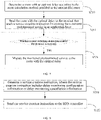
- a data transmission method is provided. As shown in FIG. 4 , the data transmission method includes steps S210 to S220.
- a route with an optimal delay is determined according to a predetermined algorithm, where the predetermined algorithm is the route calculation method provided in the present application.
- a monitored predetermined service is migrated to the route with the optimal delay in response to a predetermined condition being satisfied.
- the data transmission method provided in the present application is still executed by the SDN controller.
- the predetermined service being executed can be migrated to the route with the optimal delay, so as to ensure that the predetermined service is not only executed on the route with the optimal delay at the time of service setup, but also is executed on the route with the optimal delay in the process of service execution, thereby improving the efficiency of data transmission.
- the predetermined condition is not particularly limited.
- the SND controller may determine whether to switch the route of the predetermined service.
- the SDN controller may send information about the route with the optimal delay to the application layer to allow a corresponding application (APP) in the application layer to determine whether to switch the route.
- APP application
- the terminal sends a service creation instruction to the SDN controller through the APP.
- the data transmission method further includes a step S211.
- the route with the optimal delay is sent to the terminal that sends a service creation instruction for creating the monitored predetermined service in the application layer.
- the predetermined condition includes: reception of a route switching instruction sent by the terminal.
- the APP that generates the service creation instruction and is installed on the terminal that executes the predetermined service determines whether the route with the optimal delay reaches a threshold, and if the route with the optimal delay reaches the threshold, sends the route switching instruction.
- the route with the optimal delay is displayed, the user inputs switching information through the APP installed on the terminal, the APP converts the switching information into a route switching instruction, and the terminal delivers the route switching instruction to the SDN controller.
- the data transmission method further includes steps S212 and S213 prior to S220.
- a currently determined route with the optimal delay is compared with a route with an optimal delay that is reported during a previous execution of the predetermined service, in response to a manual switching instruction sent by an application layer;
- the currently determined route with the optimal delay is reported to the application layer in response to the currently determined route with the optimal delay being different from the route with the optimal delay reported during the previous execution.
- the situation where the SDN controller determines whether to switch the service route further includes two specific cases.
- the SDN controller determines whether to switch the service route according to a result of comparison between the route with the optimal delay and the current route.
- the SDN controller determines whether to automatically switch the service route according to a configuration attribute of the predetermined service.
- the application layer configures an "automatic route switching attribute" in the configuration attribute of the predetermined service. As long as the SDN controller can obtain this attribute, the SDN controller can switch the current route to the route with the optimal delay.
- the condition for performing S210 is not particularly limited.
- the predetermined service may be a service specified by the user. As long as the predetermined service starts to be executed, S210 is performed, i.e., the route calculation method provided in accordance with the first aspect of the present application is performed immediately.
- the predetermined service is a mail sending service specified by the user. As long as the mail sending service is executed, S210 is performed.
- a monitoring start instruction delivered by the APP of the application layer may also be used as a triggering condition for performing S210.
- the APP of the application layer delivers a delay monitoring instruction, where the delay monitoring instruction includes a delay monitoring setting instruction and a service ID list.
- the SDN controller traverses the service ID list to determine a service being executed, and takes the service as the predetermined service. S210 is then performed, i.e., the route calculation method is performed for the predetermined service.
- the data transmission method may further include: retrieving monitored service information from a database in response to an SDN controller restart instruction. That is to say, when restarted, the SDN controller can automatically recover delay data that is before the restart of the SDN controller, thereby improving the response speed.
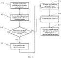
- a service processing method is provided. As shown in FIG. 5 , the data transmission method includes steps S310 to S320.
- a service creation instruction is generated, where the service creation instruction includes delay monitoring configuration information or delay monitoring cancellation information, the delay monitoring configuration information is configured for controlling the SDN controller to execute the data transmission method provided in the present application, and the delay monitoring cancellation information is configured for controlling the SDN controller to stop execution of the data transmission method of any one of claims 7 to 11.
- the service creation instruction is sent to the SDN controller.
- the SDN controller may automatically migrate the predetermined service to the optimal route.
- the service creation instruction further includes the automatic route switching information.
- the service creation instruction may further include non-automatic route switching information, and the non-automatic route switching is configured for controlling the SDN controller to report the route with the optimal delay to a terminal that creates the predetermined service. Further, the route with the optimal delay is reported to an APP that is installed on the terminal and creates the predetermined service.
- the SDN controller may further send configuration success information to the APP installed on the terminal after performing the data transmission method provided in the present application according to the delay monitoring configuration information in the service creation instruction. Certainly, if the SDN controller receives the delay monitoring configuration information but cannot perform the data transmission method provided in the present application, the SDN controller may send configuration failure information to the APP installed on the terminal.
- the SDN controller stops execution of the data transmission method provided in the present application, stores the delay monitoring configuration information in the database, and returns modification success information to the APP installed on the terminal.
- a route calculation module is provided. As shown in FIG. 10 , the route calculation module includes a monitoring unit 610 and a calculation unit 620. The route calculation module is configured for performing the route calculation method provided in accordance with the first aspect of the present application.
- the monitoring unit 610 is configured for monitoring a network resource status of a forwarding layer.
- the calculation unit 620 is configured for calculating a route with an optimal delay for a monitored predetermined service according to a changed network resource in response to a change in the network resource status of the forwarding layer.
- the route calculation module may include a data model unit 630.
- the data model unit 630 is configured for encapsulating, upon reception of a notification indicating a change in the network device topology resource, a network device topology resource before the resource change and a network device topology resource after the resource change to generate a topology resource change notification, and sending the topology resource change notification to the monitoring unit 610.
- the calculation unit 620 is configured for analyzing the topology resource change notification, and storing the route with the optimal delay in a memory.
- the change in the network device topology resource includes a change in a link resource and/or a port resource of a network device in the forwarding layer.
- the change in the network device topology resource includes at least one of: disappearing of a link alarm, presence of a new link, occurrence of release of a port resource, or presence of a new port.
- the storage form of the route with the optimal delay in the memory is not particularly limited.
- the storage form may be Map ⁇ service_id, delaymonitorinfo>.
- the specific form of the calculation unit 620 is also not particularly limited.
- the calculation unit 620 may include a delay calculation subunit 621, a delay-based routing subunit 622, and a delay measurement subunit 623.
- the delay measurement subunit 623 is configured for calculating delays of all links capable of executing the predetermined service according to the received network resource status.
- the delay-based routing subunit 622 is configured for selecting the route with the optimal delay according to a calculation result of the delay calculation subunit 621.
- the delay calculation subunit 621 may generate a link list according to the monitored network resource status.
- the delay-based routing subunit 622 may traverse the monitored service information list, and extract the monitored predetermined service from the monitored service information list.
- the delay-based routing subunit 622 may further compare a delay of a current route of the predetermined service with the link delay of each link in the link list, and determine the route with the optimal delay by determining whether the link delay of the links in the link list is lower than the delay of the current route.
- an SDN controller is further provided.
- the SDN controller provided in accordance with the fifth aspect of the present application is configured for performing the data transmission method provided in accordance with the second aspect of the present application.
- the SDN controller includes the route calculation module 710 provided in accordance with the fourth aspect of the present application and a switching module 720.
- the route calculation module 710 is configured for performing the route calculation method provided in accordance with the first aspect of the present application.
- the switching module is configured for performing S210, i.e., migrating the monitored predetermined service to the route with the optimal delay in response to a predetermined condition being satisfied.
- the data transmission method includes sending the route with the optimal delay to an APP that creates the monitored predetermined service in the application layer.
- the SDN controller may further include a delay notification module 730.
- the delay notification module 730 is configured for performing the step of "sending the route with the optimal delay to an APP that creates the monitored predetermined service in the application layer".
- the SDN controller may further include a service processing module 740.
- the service processing module 740 is configured for allocating various resources, performing path computation, and down-crossing devices in the forwarding layer.
- the SDN controller may further include a database storage module 750.
- the database storage module 750 is configured for implementing operations such as addition, deletion, modification, and query of various data, providing interfaces for accessing various data, providing interfaces for accessing various databases, and providing a data access resource pool and a data factory, etc.
- an SDN controller which includes: a storage module, storing an executable program; and one or more processors, where the executable program, when executed by the one or more processors, causes the one or more processors to carry out the route calculation method provided in accordance with the first aspect of the present application or cause the one or more processors to carry out the data transmission method provided in accordance with the second aspect of the present application.
- an SDN control system is further provided. As shown in FIG. 10 , the system includes: a northbound control management layer 120, configured for communicating with an application layer; a southbound service layer 130, configured for communicating with a forwarding layer 300; and the SDN controller 100 provided in the present application.
- the SDN controller 100 may calculate a route with an optimal delay for the service being executed currently according to the network resource status of the forwarding layer 300, thereby improving the efficiency of data transmission.
- the specific structure of the northbound control management layer 120 is not particularly limited.
- the northbound control management layer 120 includes a northbound interface module 121, a feedback module 122, and a conversion module 123.
- the northbound interface module 121 may implement at least one of the following functions: conversion of APP and SDN controller interfaces, definition of a YANG file, definition of a protobuf file, definition of an RPC method, conversion of a byte order, notification of an execution result message, monitoring, etc.
- the feedback module 122 is configured for feeding back status information of the SDN controller, link discovery information, service routing information, service migration information, service return information, link delay information, link recovery information, and real-time topology information to network management personnel.
- the feedback module 122 is configured for feeding back a communication status of a controller supervisor to the network management personnel. For example, when detecting a fault in the controller supervisor, the feedback module 122 sends an alarm to the user in time, to prompt the user to restart the SDN controller supervisor or maintain the controller supervisor.
- the conversion module 123 is mainly configured for adapting a message such as a JSON message delivered by the APP to a data format, such as a data format defined by the YANG file, for window maintenance, analog cutover, fiber cutover, and cutover rollback via northbound, and converting a data format reported by window maintenance, analog cutover, fiber cutover, and cutover rollback to a data format supported by the APP, such as a JSON data format, for reporting.
- a data format such as a data format defined by the YANG file
- the northbound control management layer 120 may further include other reserved applications 124, to implement at least one of functions of monitoring the controller, implementing software upgrade of the controller, enabling a log function, checking for memory leaks, implementing restart and maintenance of the controller supervisor, and receiving a controller selection or designation from maintenance personnel.
- the southbound service layer 130 implements communication between the SDN controller and the forwarding layer through various southbound protocols (including, but not limited to netconf, P4, openflow, etc.).
- the SDN controller is based on a microservice framework.
- the monitoring unit and the route calculation unit in the SDN controller may be released in the form of microservices.
- the specific mode of the microservice is not particularly limited.
- the monitoring unit and the route calculation unit may be released in the form of a Platform as a Service (PaaS) microservice.
- PaaS Platform as a Service
- the SDN controller provided in the present application is based on a microservice framework, the coupling degree between functional modules is low, and each functional module has the advantages of independence, easy scaling, and easy deployment.
- microservice framework means that both northbound and southbound of the SDN controller are implemented using microservices, and each module, unit, and subunit of the SDN controller is a microservice.
- northbound protocols or tools of the SDN controller are also microservices.
- the northbound protocols or tools of the SDN controller may include, but not limited to, restful, gRPC, tapi, yangtools, and the like. In this way, different versions of tapi or yangtools can coexist without interfering with each other. A change in the interfaces does not lead to incompatibility between old and new functions of the SDN controller, thereby ensuring smooth upgrading of the functions of the SDN controller.
- southbound protocols There are multiple southbound protocols for the southbound of the SDN controller. Different southbound protocols are released as microservices. Different versions of the same southbound protocol may exist at the same time, enabling the SDN controller to smoothly support new and old products. In addition, the southbound protocols can also be easily migrated to other projects, thereby improving the scalability. Since the microservices are easy to uninstall, unnecessary microservices can be easily removed when a new product is released, thereby ensuring the lightweight of the SDN controller.
- applications in the application layer 200 is not particularly limited.
- applications in the application layer may include:
- a computer-readable storage medium storing an executable program which, when executed by a processor, causes the processor to carry out the route calculation method provided in accordance with the first aspect of the present application or the data transmission method provided in accordance with the second aspect of the present application.
- a terminal device is provided. As shown in FIG. 11 , the terminal device includes an instruction generation module 810 and an instruction sending module 820.
- the instruction generation module 810 is configured for performing step S310, i.e., the instruction generation module 810 is configured for generating a service creation instruction.
- the service creation instruction includes delay monitoring configuration information or delay monitoring cancellation information.
- the delay monitoring configuration information is configured for controlling an SDN controller to execute the data transmission method provided in the present application.
- the delay monitoring cancellation information is configured for controlling the SDN controller to stop execution of the data transmission method provided in the present application.
- the instruction sending module 820 is configured for performing step S320, i.e., the instruction sending module 820 is configured for sending the service creation instruction to the SDN controller.
- a computer-readable storage medium storing an executable program which, when executed by a processor, causes the processor to carry out the service processing method provided in the present application.
- the computer-readable storage medium includes volatile and nonvolatile, removable and non-removable media implemented in any method or technology for storage of information (such as computer readable instructions, data structures, program modules, or other data).
- the computer-readable storage medium includes, but is not limited to, a random access memory (RAM), a read-only memory (ROM), an electrically erasable programmable read-only memory (EEPROM), a flash memory or other memory technology, a compact disc read-only memory (CD-ROM), a digital versatile disc (DVD) or other optical storage, a magnetic disc, a magnetic tape, a magnetic storage or other magnetic storage medium, or any other medium which can be used to store the desired information and which can be accessed by a computer.
- RAM random access memory
- ROM read-only memory
- EEPROM electrically erasable programmable read-only memory
- CD-ROM compact disc read-only memory
- DVD digital versatile disc
- FIG. 12 is a flowchart of performing the service creation method provided in Embodiment one of the present application in an SDN network, including following steps 5-1 to 5-7.
- a terminal device installed with an APP sends a user request to the northbound interface module of the SDN control system through the APP, where the user request includes a delay operation instruction.
- Methods of sending the user request include, but are not limited to, protocol interfaces such as restful, gRPC, and http.
- the northbound interface module sends a service creation request to a northbound adaptation module which receives a maintenance window creation request from the APP, adapts the maintenance window creation request to a create maintenance window request, and sends the create maintenance window request to the conversion module of the northbound control management layer, to convert the create maintenance window request to a message of a data structure type that can be processed by an SND controller.
- the SDN controller determines according to the converted service creation request whether to perform delay monitoring for a service. If yes, the process proceeds to step 5-4; otherwise, the process proceeds to step 5-5.
- service delay monitoring is configured through the SDN controller, and delay monitoring setting information is configured in an input object for service creation.
- step 5-5 whether to configure automatic route optimization for the service is determined by analyzing the user request, and whether to automatically optimize information is configured in an input object for service creation/modification.
- a service is created/modified, and a normal service creation or modification process is performed.
- the delay-based routing sub-unit stores service information in a memory and a database.
- the delay module saves service ID information in the memory to increase the speed of service optimization, and saves a service ID in the database, so that data can be recovered during restart of the controller.
- FIG. 13 is a flowchart of modifying service delay monitoring configurations in batches in Embodiment two of the present application.
- a terminal installed with an APP sends a message for modifying delay monitoring configurations in batches to the SDN controller through the APP.
- the APP sends a user request indicating batch creation of delay monitoring configurations for services to the SDN controller.
- the user request needs to include, but not limited to, delay monitoring configuration or cancellation information, automatic or non-automatic replacement of service information, a service ID list, etc.
- the SDN controller removes a service ID option from a memory Map ⁇ service id, delaymonitorinfo>, stores configuration information indicating delay monitoring cancellation in a database, and returns information indicating whether each modification is successful or fails.
- the SDN controller traverses a service list B.
- a predetermined service B1 being currently executed is selected.
- step 6-4 determines whether the process is a determination result at step 6-4 is yes. If a determination result at step 6-4 is yes, the process proceeds to step 6-5; otherwise the process proceeds to step 6-7.
- a northbound microservice module calls a data storage interface, stores the route with the optimal delay in a database, and returns information indicating whether each modification is successful or fails.
- step 6-7 a determination is made as to whether the traversal of the service list B has been completed.
- step 6-7 When a determination result at step 6-7 is yes, the process ends; otherwise, the process goes back to step 6-2.
- the northbound calls a delay monitoring module to modify monitored service IDs maintained in the memory, and stores the service ID and delay monitoring information in the memory, e.g., Map ⁇ service_id, delaymonitorinfo>.
- the storage method is to put the service ID, automatic or non-automatic replacement, and a pre-calculation result in a class DelayMonitorInfo.java, and then store the same in the form of a Map ⁇ service_id, delaymonitorinfo> to facilitate the maintenance of delay configuration information and the returning of a result indicating whether the configuration is successful or fails.
- FIG. 14 is a flowchart of delay-based routing in the case of resource addition in Embodiment three of the present application, which includes following steps 7-1 to 7-15.
- a data model unit receives a change in a network device topology resource of a forwarding layer, and sends a resource change notification.
- the data model unit receives and analyzes a notification of the change in the network device topology resource, encapsulates information such as notifications before and after the resource change, and sends a notification indicating a change in link and port resources, including, but not limited to, disappearing of a link alarm, presence of a new link, occurrence of release of a port resource, presence of a new port, etc.
- a monitoring unit detects the data change notification and determines that a resource is added.
- the monitoring unit as a delay microservice detects the notification, analyzes information about the added resources, performs different processing on different resources, and stores the information in an object in a delay memory.
- the memory may be in the form of, for example, but not limited to, Map ⁇ service id, delaymonitorinfo>.
- a delay-based routing subunit obtains, from the memory, a service information list B on which delay monitoring is performed.
- the delay-based routing subunit obtains, from the memory Map ⁇ service _id, delaymonitorinfo>, the service information list B on which delay monitoring is performed.
- a delay-based routing subunit obtains, from the memory, a service information list B on which delay monitoring is performed.
- the delay-based routing subunit obtains, from the memory Map ⁇ service _id, delaymonitorinfo>, the service information list B on which delay monitoring is performed.
- step 7-4 and step 7-5 the service information list B on which delay monitoring is performed is traversed, and a current service B1 is selected.
- step 7-6 a determination is made through pre-calculation as to whether there is a better route. Pre-calculation is performed according to information of the service B1 to determine whether there is a better route. If yes, the process proceeds to step 7-7; otherwise, the process proceeds to step 7-10.
- step 7-7 a determination is made as to whether to automatically replace the service.
- step 7-7 If a determination result at step 7-7 is yes, the process proceeds to step 7-8; otherwise, the process proceeds to step 7-11.
- a delay module calls a service module interface to implement service optimization and replacement.
- a route optimization result is reported to an APP.
- the delay module sends a notification to a northbound structure module. After receiving the notification, the northbound structure module sends a notification to the APP to notify the APP of the route optimization result.
- step 7-10 a determination is made as to whether the traversal of the service list B has been completed.
- step 7-10 If a determination result at step 7-10 is yes, the process ends; otherwise, the process goes back to step 7-4.
- a pre-calculation result is reported to the APP.
- the SDN controller calls a pre-calculation interface. If the pre-calculation is successful, a delay of a pre-calculated route is compared with a delay of a current service route. If the delay of the pre-calculated route is shorter than the delay of the current service route, a comparison is made as to whether the pre-calculated route is the same as a previously reported route. If not, the calculated route with the optimal delay is reported to the APP.
- the APP prompts the user whether to perform path optimization.
- step 7-12 If the result at step 7-12 is yes, the process proceeds to step 7-13; otherwise, the process goes back to step 7-5.
- the APP calls an interface for creating a preset path.
- a path computation module generates an available path, and returns a result to the APP.
- the APP calls an interface for performing path optimization, to perform a path rerouting function according to the path generated through path computation at step 7-13, and return a result to the APP.
- the APP calls an interface for deleting a preset path, to release a resource, and return a result to the APP.
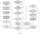
- FIG. 15 is a flowchart of delay-based routing in the case of a link change in Embodiment four of the present application, which includes steps 8-1 to 8-18.
- a data model unit receives a change in a device topology resource, and sends a resource change notification.
- the data model unit receives and analyzes a notification of the change in the device topology resource, encapsulates information such as notifications before and after the resource change, and sends a notification indicating a change in link and port resources.
- a monitoring unit detects the data change notification and determines that a link delay changes. Whether the link delay increases or decreases is determined by, for example, but not limited to, performing subtraction between a delay before the change (before delay) and a delay after the change (after delay).
- a delay-based routing subunit detects a notification of a link change, and generates a link list A.
- the delay-based routing subunit obtains, from a memory, a service information list B on which delay monitoring is performed.
- step 8-5 the service list B is traversed.
- a current service B1 is selected from the service list B.
- step 8-7 a comparison with the link list A is performed to determine whether there is an increased link delay in the service B1. If the determination result at step 8-7 is yes, the process proceeds to step 8-9; otherwise, the process proceeds to step 8-8.
- step 8-8 a determination is made as to whether there is a delay-decreased link in the link list A that is not on the service B1. If the determination result at step 8-8 is yes, the process proceeds to step 8-9; otherwise, the process proceeds to step 8-18.
- step 8-9 a determination is made through pre-calculation as to whether there is a better route.
- the controller calls a pre-calculation interface. If a determination is made at step 8-9 that there is a better route, the process proceeds to step 8-10; otherwise, the process proceeds to step 8-18.
- step 8-10 a determination is made as to whether to automatically replace the service. If the determination result at step 8-10 is yes, service optimization and replacement are performed; otherwise, the process proceeds to step 8-13.
- step 8-11 service optimization and replacement are performed, and the switching module calls a service module interface to realize service optimization and replacement.
- a route optimization result is reported to the APP.
- the delay module sends a notification to the northbound module. After receiving the notification, the northbound module sends a notification to the APP to notify the APP of the route optimization result.
- a pre-calculation result is reported to the APP.
- the SDN controller calls a pre-calculation interface. If the pre-calculation is successful, a delay of a pre-calculated route is compared with a delay of a current service route. If the delay of the pre-calculated route is shorter than the delay of the current service route, a comparison is made as to whether the pre-calculated route is the same as a previously reported route. If not, the new route is reported to the APP.
- step 8-14 the APP prompts the user whether to perform path optimization. If "yes” selected by the user is received, the process proceeds to step 8-15; if "no" selected by the user is received, the process proceeds to step 8-18.
- the APP calls an interface for creating a preset path.
- An available path is generated by path computation.
- a result is returned to the APP.
- the APP calls an interface for performing path optimization, to perform a path rerouting function according to the path generated by the path computation at step 8-5, and return a result to the APP.
- the APP calls an interface for deleting a preset path, to release a path computation resource, and return a result to the APP.
- step 8-18 a determination is made as to whether the traversal of the service list B has been completed. If the determination result at step 8-18 is yes, the process ends; otherwise, the process goes back to step 8-5, and services are continued to be traversed.
Landscapes
- Engineering & Computer Science (AREA)
- Computer Networks & Wireless Communication (AREA)
- Signal Processing (AREA)
- Data Exchanges In Wide-Area Networks (AREA)
Applications Claiming Priority (2)
| Application Number | Priority Date | Filing Date | Title |
|---|---|---|---|
| CN201911396549.6A CN113132237A (zh) | 2019-12-30 | 2019-12-30 | 路由计算方法和数据传输方法 |
| PCT/CN2020/131839 WO2021135746A1 (fr) | 2019-12-30 | 2020-11-26 | Procédé de calcul de route et procédé de transmission de données |
Publications (2)
| Publication Number | Publication Date |
|---|---|
| EP4072082A1 true EP4072082A1 (fr) | 2022-10-12 |
| EP4072082A4 EP4072082A4 (fr) | 2023-02-08 |
Family
ID=76687286
Family Applications (1)
| Application Number | Title | Priority Date | Filing Date |
|---|---|---|---|
| EP20908493.8A Withdrawn EP4072082A4 (fr) | 2019-12-30 | 2020-11-26 | Procédé de calcul de route et procédé de transmission de données |
Country Status (3)
| Country | Link |
|---|---|
| EP (1) | EP4072082A4 (fr) |
| CN (1) | CN113132237A (fr) |
| WO (1) | WO2021135746A1 (fr) |
Families Citing this family (3)
| Publication number | Priority date | Publication date | Assignee | Title |
|---|---|---|---|---|
| CN114745763B (zh) * | 2022-03-08 | 2023-08-22 | 深圳市欣博跃电子有限公司 | 一种更新最佳网络拓扑的方法及系统 |
| CN115150324B (zh) * | 2022-06-09 | 2024-05-10 | 南京邮电大学 | 一种基于可编程数据平面实现可变重路由阈值的方法及系统 |
| CN115190025B (zh) * | 2022-06-13 | 2023-07-25 | 安世亚太科技股份有限公司 | 一种基于动态均衡的网络数字孪生体资源优化方法 |
Family Cites Families (6)
| Publication number | Priority date | Publication date | Assignee | Title |
|---|---|---|---|---|
| US9571384B2 (en) * | 2013-08-30 | 2017-02-14 | Futurewei Technologies, Inc. | Dynamic priority queue mapping for QoS routing in software defined networks |
| CN105790990B (zh) * | 2014-12-24 | 2019-03-22 | 国家电网公司 | 一种监管配用电通信业务的方法及其系统 |
| CN105871755A (zh) * | 2016-06-06 | 2016-08-17 | 中国电子科技集团公司第三十研究所 | 一种基于sdn的网络资源分配方法和系统 |
| CN106130767B (zh) * | 2016-09-23 | 2020-04-07 | 深圳灵动智网科技有限公司 | 一种业务路径故障监控及故障解决的系统和方法 |
| CN108512760B (zh) * | 2018-03-09 | 2020-07-28 | 西安电子科技大学 | 基于SDN保障业务QoS的路由方法 |
| CN108768713A (zh) * | 2018-05-09 | 2018-11-06 | 西安工业大学 | SDN中的一种保障QoS动态路由算法 |
-
2019
- 2019-12-30 CN CN201911396549.6A patent/CN113132237A/zh active Pending
-
2020
- 2020-11-26 EP EP20908493.8A patent/EP4072082A4/fr not_active Withdrawn
- 2020-11-26 WO PCT/CN2020/131839 patent/WO2021135746A1/fr not_active Ceased
Also Published As
| Publication number | Publication date |
|---|---|
| EP4072082A4 (fr) | 2023-02-08 |
| CN113132237A (zh) | 2021-07-16 |
| WO2021135746A1 (fr) | 2021-07-08 |
Similar Documents
| Publication | Publication Date | Title |
|---|---|---|
| CN108270669B (zh) | Sdn网络的业务恢复装置、主控制器、系统及方法 | |
| US9634900B2 (en) | Declarative approach to virtual network creation and operation | |
| CN108449350B (zh) | 一种多协议编排方法及装置 | |
| EP3518465B1 (fr) | Procédé et dispositif d'initiation de modification de logiciel | |
| JP6817322B2 (ja) | 分散型ウェットプラントマネージャーを有する光通信システム | |
| EP3796667B1 (fr) | Procédé et appareil de basculement de fibre optique, dispositif de commande sdn, système et support d'enregistrement | |
| US20210240448A1 (en) | System configuration derivation device and system configuration derivation method | |
| CN114095348B (zh) | 网络能力开放系统及业务编排方法 | |
| WO2021135746A1 (fr) | Procédé de calcul de route et procédé de transmission de données | |
| CN112448987A (zh) | 一种熔断降级的触发方法、系统和存储介质 | |
| CN115001990B (zh) | 一种基于声明式API的跨地域openstack集群管理方法及系统 | |
| WO2025040039A1 (fr) | Système de parution en niveaux de gris non intrusif à mise à l'échelle automatique | |
| WO2022016969A1 (fr) | Procédé et dispositif de traitement de données | |
| KR20170108136A (ko) | 소프트웨어-정의 네트워킹 제어기 | |
| US20250373555A1 (en) | Programmable Path Computation Engine | |
| US12237975B2 (en) | Cloud-native approach to support desired state model reconciliation with networking equipment | |
| CN116795483A (zh) | 一种资源处理方法和装置、及存储介质 | |
| CN101969381A (zh) | 一种自动交换光网络中业务恢复方法和装置 | |
| CN114531393A (zh) | 分段路由策略下发方法、装置、设备、介质及程序产品 | |
| WO2015162619A1 (fr) | Gestion d'échecs de liaison dans des réseaux définis par logiciel | |
| CN113312059A (zh) | 一种服务处理系统、方法及云原生系统 | |
| CN109033483A (zh) | 一种在yang模型中定义数据关系的方法、装置及系统 | |
| KR102936225B1 (ko) | 소프트웨어 정의 네트워킹을 위한 우선순위 조정 방법 및 장치 | |
| WO2016065925A1 (fr) | Dispositif et procédé de remplacement de contrôleur | |
| CN109547439B (zh) | 一种服务节点接入网络的处理方法及装置 |
Legal Events
| Date | Code | Title | Description |
|---|---|---|---|
| STAA | Information on the status of an ep patent application or granted ep patent |
Free format text: STATUS: THE INTERNATIONAL PUBLICATION HAS BEEN MADE |
|
| PUAI | Public reference made under article 153(3) epc to a published international application that has entered the european phase |
Free format text: ORIGINAL CODE: 0009012 |
|
| STAA | Information on the status of an ep patent application or granted ep patent |
Free format text: STATUS: REQUEST FOR EXAMINATION WAS MADE |
|
| 17P | Request for examination filed |
Effective date: 20220707 |
|
| AK | Designated contracting states |
Kind code of ref document: A1 Designated state(s): AL AT BE BG CH CY CZ DE DK EE ES FI FR GB GR HR HU IE IS IT LI LT LU LV MC MK MT NL NO PL PT RO RS SE SI SK SM TR |
|
| REG | Reference to a national code |
Ref country code: DE Ref legal event code: R079 Free format text: PREVIOUS MAIN CLASS: H04L0012727000 Ipc: H04L0045020000 |
|
| A4 | Supplementary search report drawn up and despatched |
Effective date: 20230109 |
|
| RIC1 | Information provided on ipc code assigned before grant |
Ipc: H04W 40/34 20090101ALN20230102BHEP Ipc: H04L 47/283 20220101ALN20230102BHEP Ipc: H04L 45/76 20220101ALI20230102BHEP Ipc: H04L 45/121 20220101ALI20230102BHEP Ipc: H04L 45/00 20220101ALI20230102BHEP Ipc: H04L 45/02 20220101AFI20230102BHEP |
|
| DAV | Request for validation of the european patent (deleted) | ||
| DAX | Request for extension of the european patent (deleted) | ||
| STAA | Information on the status of an ep patent application or granted ep patent |
Free format text: STATUS: EXAMINATION IS IN PROGRESS |
|
| 17Q | First examination report despatched |
Effective date: 20251002 |
|
| STAA | Information on the status of an ep patent application or granted ep patent |
Free format text: STATUS: THE APPLICATION HAS BEEN WITHDRAWN |
|
| 18W | Application withdrawn |
Effective date: 20260105 |