EP4072200A1 - Relaiskommunikationsverfahren und -vorrichtung - Google Patents
Relaiskommunikationsverfahren und -vorrichtung Download PDFInfo
- Publication number
- EP4072200A1 EP4072200A1 EP20909581.9A EP20909581A EP4072200A1 EP 4072200 A1 EP4072200 A1 EP 4072200A1 EP 20909581 A EP20909581 A EP 20909581A EP 4072200 A1 EP4072200 A1 EP 4072200A1
- Authority
- EP
- European Patent Office
- Prior art keywords
- user equipment
- network device
- identifier
- relay
- sidelink
- Prior art date
- Legal status (The legal status is an assumption and is not a legal conclusion. Google has not performed a legal analysis and makes no representation as to the accuracy of the status listed.)
- Pending
Links
Images


Classifications
-
- H—ELECTRICITY
- H04—ELECTRIC COMMUNICATION TECHNIQUE
- H04W—WIRELESS COMMUNICATION NETWORKS
- H04W76/00—Connection management
- H04W76/10—Connection setup
- H04W76/14—Direct-mode setup
-
- H—ELECTRICITY
- H04—ELECTRIC COMMUNICATION TECHNIQUE
- H04W—WIRELESS COMMUNICATION NETWORKS
- H04W40/00—Communication routing or communication path finding
- H04W40/02—Communication route or path selection, e.g. power-based or shortest path routing
- H04W40/22—Communication route or path selection, e.g. power-based or shortest path routing using selective relaying for reaching a BTS [Base Transceiver Station] or an access point
-
- H—ELECTRICITY
- H04—ELECTRIC COMMUNICATION TECHNIQUE
- H04W—WIRELESS COMMUNICATION NETWORKS
- H04W28/00—Network traffic management; Network resource management
- H04W28/02—Traffic management, e.g. flow control or congestion control
- H04W28/08—Load balancing or load distribution
- H04W28/0875—Load balancing or load distribution to or through Device to Device [D2D] links, e.g. direct-mode links
-
- H—ELECTRICITY
- H04—ELECTRIC COMMUNICATION TECHNIQUE
- H04W—WIRELESS COMMUNICATION NETWORKS
- H04W28/00—Network traffic management; Network resource management
- H04W28/02—Traffic management, e.g. flow control or congestion control
- H04W28/08—Load balancing or load distribution
- H04W28/09—Management thereof
- H04W28/0958—Management thereof based on metrics or performance parameters
-
- H—ELECTRICITY
- H04—ELECTRIC COMMUNICATION TECHNIQUE
- H04W—WIRELESS COMMUNICATION NETWORKS
- H04W48/00—Access restriction; Network selection; Access point selection
- H04W48/20—Selecting an access point
-
- H—ELECTRICITY
- H04—ELECTRIC COMMUNICATION TECHNIQUE
- H04W—WIRELESS COMMUNICATION NETWORKS
- H04W72/00—Local resource management
- H04W72/12—Wireless traffic scheduling
- H04W72/121—Wireless traffic scheduling for groups of terminals or users
-
- H—ELECTRICITY
- H04—ELECTRIC COMMUNICATION TECHNIQUE
- H04W—WIRELESS COMMUNICATION NETWORKS
- H04W72/00—Local resource management
- H04W72/50—Allocation or scheduling criteria for wireless resources
- H04W72/54—Allocation or scheduling criteria for wireless resources based on quality criteria
- H04W72/542—Allocation or scheduling criteria for wireless resources based on quality criteria using measured or perceived quality
-
- H—ELECTRICITY
- H04—ELECTRIC COMMUNICATION TECHNIQUE
- H04W—WIRELESS COMMUNICATION NETWORKS
- H04W76/00—Connection management
- H04W76/10—Connection setup
- H04W76/11—Allocation or use of connection identifiers
-
- H—ELECTRICITY
- H04—ELECTRIC COMMUNICATION TECHNIQUE
- H04W—WIRELESS COMMUNICATION NETWORKS
- H04W8/00—Network data management
- H04W8/005—Discovery of network devices, e.g. terminals
-
- H—ELECTRICITY
- H04—ELECTRIC COMMUNICATION TECHNIQUE
- H04W—WIRELESS COMMUNICATION NETWORKS
- H04W16/00—Network planning, e.g. coverage or traffic planning tools; Network deployment, e.g. resource partitioning or cells structures
- H04W16/24—Cell structures
- H04W16/26—Cell enhancers or enhancement, e.g. for tunnels, building shadow
-
- H—ELECTRICITY
- H04—ELECTRIC COMMUNICATION TECHNIQUE
- H04W—WIRELESS COMMUNICATION NETWORKS
- H04W24/00—Supervisory, monitoring or testing arrangements
- H04W24/10—Scheduling measurement reports ; Arrangements for measurement reports
-
- H—ELECTRICITY
- H04—ELECTRIC COMMUNICATION TECHNIQUE
- H04W—WIRELESS COMMUNICATION NETWORKS
- H04W88/00—Devices specially adapted for wireless communication networks, e.g. terminals, base stations or access point devices
- H04W88/02—Terminal devices
- H04W88/04—Terminal devices adapted for relaying to or from another terminal or user
Definitions
- Embodiments of this application relate to the field of communications technologies, and in particular, to a relay communication method and a communications apparatus.
- a mechanism of user equipment (user equipment, UE) cooperation communication is introduced into a 5th generation (5th generation, 5G) new radio (new radio, NR) system.
- 5th generation, 5G 5th generation
- UE user equipment
- NR new radio
- an operator may deploy a plurality of cooperating user equipments (cooperating UEs, CUEs), and each CUE has a strong capability, and may be installed with more receive antennas and transmit antennas.
- the CUE may assist target user equipment (target UE, TUE) in forwarding data.
- the TUE may discover and select one appropriate CUE from the plurality of CUEs, establish a connection to the selected CUE, and use the CUE to send data to a network device or receive data sent by the network device. In this way, the coverage and the system capacity are improved.
- a process of discovering and selecting CUE by TUE includes: The TUE sends a discovery request message to a plurality of CUEs. Each CUE sends a response message to the TUE after receiving the discovery request message. The TUE receives and measures the response messages sent by the plurality of CUEs, to obtain signal quality between each CUE and the TUE. The TUE selects, based on the signal quality between each CUE and the TUE, CUE for data forwarding in the plurality of CUEs, and communicates with a network device via the CUE.
- the TUE selects the CUE based on the signal quality between the TUE and the CUE, and forwards data via the selected CUE.
- the TUE can monitor only a status of a channel between the TUE and CUE, and information for CUE selection is limited. Consequently, performance of the selected CUE is not good enough, and data forwarding performed via the CUE selected by the TUE cannot meet a performance requirement of a network system.
- Embodiments of this application provide a relay communication method and a communications apparatus, to resolve a problem that communications system performance cannot be met because relay UE is selected by remote UE to forward data in existing relay communication.
- this application provides a relay communication method.
- the method includes: A network device obtains a measurement report that includes signal quality of a sidelink (sidelink, SL) between first user equipment and at least one second user equipment and a radio network identifier of the at least one second user equipment.
- the network device selects target relay user equipment, of the first user equipment, from the at least one second user equipment based on the measurement report and selection assistance information associated with each second user equipment.
- the network device may select the appropriate target relay user equipment based on signal quality of an SL between the first user equipment and second user equipment, the selection assistance information associated with each second user equipment, and the like, and notify the first user equipment of the selected relay user equipment.
- the first user equipment is triggered to establish an SL connection to the selected relay user equipment, and communicates with the network device via the relay user equipment that establishes the SL connection to the first user equipment.
- the network device selects the appropriate relay user equipment based on an entire-network communication status such as a communication status between the first user equipment and the second user equipment and other selection assistance information. Selecting the appropriate relay user equipment by comprehensively considering entire-network system performance improves reliability of data transmission performed by remote user equipment via the relay user equipment, and improves a performance requirement of a network system.
- the selection assistance information includes one or more of the following information: subscription information of the second user equipment, air interface signal quality of the second user equipment, air interface signal quality of the first user equipment, load information of the second user equipment, and interference information of the second user equipment.
- parameter information that affects communication between the first user equipment and the second user equipment may be used as the selection assistance information for the network device to select the appropriate relay user equipment.
- factors that affect relay communication can be considered more comprehensively and systematically, to improve accuracy of the selected relay user equipment and improve system performance.
- a network device obtains a measurement report includes: The network device receives the measurement report from the first user equipment over an air interface between the network device and the first user equipment. Alternatively, the network device receives the measurement report from one second user equipment selected by the first user equipment from the at least one second user equipment. Alternatively, the network device receives signal quality of a sidelink between each second user equipment and the first user equipment and a radio network identifier of the second user equipment from the second user equipment over an air interface between the network device and the second user equipment.
- the network device may directly receive the measurement report sent by the first user equipment, may receive the measurement report sent by the first user equipment via the relay user equipment, or may receive the signal quality between each second user equipment and the first user equipment and the radio network identifier of the second user equipment that are sent by the second user equipment, and include, in the measurement report, the information sent by the second user equipment. In this way, the network device obtains the measurement report in a plurality of possible manners, to improve flexibility and diversity of obtaining the measurement report.
- the method further includes: The network device obtains a sidelink identifier that is of the at least one second user equipment and that is used for SL communication between the first user equipment and the second user equipment. Based on the possible implementation, the network device may obtain a sidelink identifier of each second user equipment, so that the network device sends the obtained sidelink identifier of the second user equipment to the first user equipment.
- the first user equipment establishes an SL connection to the second user equipment based on the sidelink identifier of the second user equipment, and performs SL communication by using the sidelink identifier of the second user equipment as a destination address. Implementation is simple and practicable.
- the method further includes: The network device sends a radio network identifier of the target relay user equipment and/or a sidelink identifier of the target relay user equipment to the first user equipment.
- the network device may send one or more of the radio network identifier and the sidelink identifier that are of the target relay user equipment to the first user equipment, so that the first user equipment establishes the SL connection to the second user equipment based on the received information, to perform SL communication.
- Implementation is simple and practicable.
- the method further includes: The network device obtains a radio network identifier of the first user equipment and/or a sidelink identifier of the first user equipment, where the radio network identifier of the first user equipment is allocated by the network device, and the sidelink identifier of the first user equipment is used for SL communication between the first user equipment and the at least one second user equipment.
- the network device may obtain the radio network identifier and the sidelink identifier that are of the first user equipment, so that the network device sends the obtained radio network identifier and/or sidelink identifier of the first user equipment to the second user equipment.
- the second user equipment establishes the SL connection to the first user equipment based on the sidelink identifier of the first user equipment, and performs SL communication by using the sidelink identifier of the first user equipment as a destination address. Implementation is simple and practicable.
- the method further includes: The network device sends, to the target relay user equipment, an announcement message used to trigger the target relay user equipment to establish an SL connection to the first user equipment, where the announcement message includes the radio network identifier of the first user equipment and/or the sidelink identifier of the first user equipment.
- the network device may notify the selected target relay user equipment of one or more of the following information: the radio network identifier and the sidelink identifier that are of the first user equipment, so that the target relay user equipment initiates establishment of the SL connection to the first user equipment based on one or more of the following information: the radio network identifier and the sidelink identifier that are of the first user equipment, and performs SL communication through the established SL connection.
- the method further includes: The network device sends, to the target relay user equipment, group scheduling information used to schedule data of communication between the first user equipment and the network device, where the group scheduling information includes a group radio network temporary identifier (group radio network temporary identifier, G-RNTI) for group scheduling and time-frequency domain information for group scheduling.
- group radio network temporary identifier group radio network temporary identifier, G-RNTI
- the network device may send the group scheduling information to the selected target relay user equipment, so that the relay user equipment monitors the corresponding G-RNTI on a time domain resource and a frequency domain resource that are indicated by the time-frequency domain information, and receives the data forwarded to the first user equipment.
- the network device can multicast the data of the first user equipment to a plurality of relay user equipments, so that the plurality of relay user equipments simultaneously forward the data for the first user equipment, to improve data transmission efficiency and reliability.
- the method further includes: The network device configures, for the first user equipment, a trigger condition used to trigger the first user equipment to send a discovery request message to the at least one second user equipment. Based on the possible implementation, the network device may configure, for the first user equipment, the trigger condition for triggering the first user equipment to initiate a discovery procedure, so that the first user equipment sends the discovery request message to the at least one second user equipment when the trigger condition is met. This sets a time limit for initiating the discovery procedure, so that the first user equipment initiates the discovery procedure only when an appropriate trigger condition is met. This avoids a problem of high power consumption caused by initiating the discovery procedure by the first user equipment at any time.
- the trigger condition includes that the air interface signal quality of the first user equipment is less than or equal to a first threshold.
- that the air interface signal quality of the first user equipment is less than or equal to a first threshold may be set as the trigger condition for initiating the discovery procedure by the first user equipment, so that the first user equipment initiates the discovery procedure when the air interface signal quality is poor and relay user equipment needs to perform data forwarding. This improves data transmission reliability.
- this application provides a communications apparatus.
- the communications apparatus may be a network device or a chip or a system-on-a-chip in the network device, or may be a functional module that is in the network device and that is configured to implement the method according to any one of the first aspect or the possible designs of the first aspect.
- the communications apparatus may implement functions performed by the network device in the foregoing aspect or the possible designs, and the functions may be implemented by hardware by executing corresponding software.
- the hardware or the software includes one or more modules corresponding to the functions.
- the communications apparatus includes an obtaining unit and a selection unit.
- the obtaining unit is configured to obtain a measurement report that includes signal quality of an SL between first user equipment and at least one second user equipment and a radio network identifier of the at least one second user equipment.
- the selection unit is configured to select target relay user equipment, of the first user equipment, from the at least one second user equipment based on the measurement report and selection assistance information associated with each second user equipment.
- the communications apparatus refer to behavior functions of the network device in the relay communication method provided in any one of the first aspect or the possible designs of the first aspect.
- the communications apparatus may select the appropriate target relay user equipment based on signal quality of an SL between the first user equipment and second user equipment, the selection assistance information associated with each second user equipment, and the like, and notify the first user equipment of the selected relay UE.
- the first user equipment is triggered to establish an SL connection to the selected relay user equipment, and communicates with the communications apparatus via the relay user equipment that establishes the SL connection to the first user equipment.
- the communications apparatus selects the appropriate relay user equipment based on an entire-network communication status such as a communication status between the first user equipment and the second user equipment and other selection assistance information.
- the selection assistance information includes one or more of the following information: subscription information of the second user equipment, air interface signal quality of the second user equipment, air interface signal quality of the first user equipment, load information of the second user equipment, and interference information of the second user equipment.
- parameter information that affects communication between the first user equipment and the second user equipment may be used as the selection assistance information for the communications apparatus to select the appropriate relay user equipment.
- factors that affect relay communication can be considered more comprehensively and systematically, to improve accuracy of the selected relay user equipment and improve system performance.
- the obtaining unit is specifically configured to: receive the measurement report from the first user equipment over an air interface between the communications apparatus and the first user equipment; receive the measurement report from one second user equipment selected by the first user equipment from the at least one second user equipment; or receive signal quality of a sidelink between each second user equipment and the first user equipment and a radio network identifier of the second user equipment from the second user equipment over an air interface between the communications apparatus and the second user equipment.
- the communications apparatus may directly receive the measurement report sent by the first user equipment, may receive the measurement report sent by the first user equipment via the relay user equipment, or may receive the signal quality between each second user equipment and the first user equipment and the radio network identifier of the second user equipment that are sent by the second user equipment, and include, in the measurement report, the information sent by the second user equipment.
- the communications apparatus obtains the measurement report in a plurality of possible manners, to improve flexibility and diversity of obtaining the measurement report.
- the obtaining unit is further configured to obtain a sidelink identifier that is of the at least one second user equipment and that is used for SL communication between the first user equipment and the second user equipment.
- the communications apparatus may obtain a sidelink identifier of each second user equipment, so that the communications apparatus sends the obtained sidelink identifier of the second user equipment to the first user equipment.
- the first user equipment establishes an SL connection to the second user equipment based on the sidelink identifier of the second user equipment, and performs SL communication by using the sidelink identifier of the second user equipment as a destination address. Implementation is simple and practicable.
- the communications apparatus further includes: a sending unit, configured to send a radio network identifier of the target relay user equipment and/or a sidelink identifier of the target relay user equipment to the first user equipment.
- the communications apparatus may send one or more of the radio network identifier and the sidelink identifier that are of the target relay user equipment to the first user equipment, so that the first user equipment establishes the SL connection to the second user equipment based on the received information, to perform SL communication.
- Implementation is simple and practicable.
- the obtaining unit is further configured to obtain a radio network identifier of the first user equipment and/or a sidelink identifier of the first user equipment, where the radio network identifier of the first user equipment is allocated by the communications apparatus, and the sidelink identifier of the first user equipment is used for SL communication between the first user equipment and the at least one second user equipment.
- the communications apparatus may obtain the radio network identifier and the sidelink identifier that are of the first user equipment, so that the communications apparatus sends the obtained radio network identifier and/or sidelink identifier of the first user equipment to the second user equipment.
- the second user equipment establishes the SL connection to the first user equipment based on the sidelink identifier of the first user equipment, and performs SL communication by using the sidelink identifier of the first user equipment as a destination address. Implementation is simple and practicable.
- the method further includes: a sending unit, configured to send, to the target relay user equipment, an announcement message used to trigger the target relay user equipment to establish an SL connection to the first user equipment, where the announcement message includes the radio network identifier of the first user equipment and/or the sidelink identifier of the first user equipment.
- the communications apparatus may notify the selected target relay user equipment of one or more of the following information: the radio network identifier and the sidelink identifier that are of the first user equipment, so that the target relay user equipment initiates establishment of the SL connection to the first user equipment based on one or more of the following information: the radio network identifier and the sidelink identifier that are of the first user equipment, and performs SL communication through the established SL connection.
- Implementation is simple and practicable.
- the method further includes: a sending unit, configured to send, to the target relay user equipment, group scheduling information used to schedule data of communication between the first user equipment and the communications apparatus, where the group scheduling information includes a group radio network temporary identifier (group radio network temporary identifier, G-RNTI) for group scheduling and time-frequency domain information for group scheduling.
- group scheduling information includes a group radio network temporary identifier (group radio network temporary identifier, G-RNTI) for group scheduling and time-frequency domain information for group scheduling.
- the communications apparatus may send the group scheduling information to the selected target relay user equipment, so that the relay user equipment monitors the corresponding G-RNTI on a time domain resource and a frequency domain resource that are indicated by the time-frequency domain information, and receives the data forwarded to the first user equipment.
- the communications apparatus can multicast the data of the first user equipment to a plurality of relay user equipments, so that the plurality of relay user equipments simultaneously forward the data for the first user equipment, to improve data transmission efficiency and reliability.
- the method further includes: a configuration unit, configured to configure, for the first user equipment, a trigger condition used to trigger the first user equipment to send a discovery request message to the at least one second user equipment.
- the communications apparatus may configure, for the first user equipment, the trigger condition for triggering the first user equipment to initiate a discovery procedure, so that the first user equipment sends the discovery request message to the at least one second user equipment when the trigger condition is met.
- This sets a time limit for initiating the discovery procedure so that the first user equipment initiates the discovery procedure only when an appropriate trigger condition is met. This avoids a problem of high power consumption caused by initiating the discovery procedure by the first user equipment at any time.
- the trigger condition includes that the air interface signal quality of the first user equipment is less than or equal to a first threshold.
- that the air interface signal quality of the first user equipment is less than or equal to a first threshold may be set as the trigger condition for initiating the discovery procedure by the first user equipment, so that the first user equipment initiates the discovery procedure when the air interface signal quality is poor and relay user equipment needs to perform data forwarding. This improves data transmission reliability.
- a communications apparatus may be a network device, or a chip or a system-on-a-chip in the network device.
- the communications apparatus may implement functions performed by the network device in the foregoing aspects or possible designs.
- the functions may be implemented by hardware.
- the communications apparatus may include a processor and a transceiver.
- the processor is configured to obtain a measurement report that includes signal quality of an SL between first user equipment and at least one second user equipment and a radio network identifier of the at least one second user equipment via the transceiver.
- the network device selects target relay user equipment, of the first user equipment, from the at least one second user equipment based on the measurement report and selection assistance information associated with each second user equipment.
- the communications apparatus may further include a memory.
- the memory is configured to store computer-executable instructions and data that are necessary for the communications apparatus.
- the processor executes the computer-executable instructions stored in the memory, so that the communications apparatus performs the relay communication method according to any one of the first aspect or the possible designs of the first aspect.
- a computer-readable storage medium is provided.
- the computer-readable storage medium may be a readable non-volatile storage medium.
- the computer-readable storage medium stores computer instructions or a program. When the computer instructions or the program is run on a computer, the computer is enabled to perform the relay communication method according to any one of the first aspect or the possible designs of the foregoing aspect.
- a computer program product including instructions is provided.
- the computer program product runs on a computer, the computer is enabled to perform the relay communication method according to any one of the first aspect or the possible designs of the foregoing aspect.
- a communications apparatus may be a network device, or a chip or a system-on-a-chip in the network device.
- the communications apparatus includes one or more processors and one or more memories.
- the one or more memories are coupled to the one or more processors, and the one or more memories are configured to store computer program code.
- the computer program code includes computer instructions.
- a chip system includes one or more processors and one or more memories.
- the one or more memories are coupled to the one or more processors, and the one or more memories store computer program code or computer instructions.
- the chip system is enabled to perform the relay communication method according to any one of the first aspect or the possible designs of the first aspect.
- an embodiment of this application provides another relay communication method.
- the method includes: First user equipment sends a measurement report that includes signal quality of a sidelink between the first user equipment and at least one second user equipment and a radio network identifier of the at least one second user equipment to a network device, and receives a radio network identifier of target relay user equipment from the network device, where the target relay user equipment is one second user equipment selected from the at least one second user equipment.
- the first user equipment establishes a sidelink SL connection to the target relay user equipment based on the radio network identifier of the target relay user equipment, and communicates with the network device via the target relay user equipment.
- the first user equipment may send the signal quality between the first user equipment and the at least one second user equipment to the network device, so that the network device selects the appropriate target relay user equipment based on signal quality of an SL between the first user equipment and second user equipment, selection assistance information associated with each second user equipment, and the like, and notifies the first user equipment of the selected relay user equipment.
- the first user equipment After receiving a selection result of the network device, the first user equipment is triggered to establish the SL connection to the selected relay user equipment, and communicates with the network device via the relay user equipment that establishes the SL connection to the first user equipment.
- the network device selects the appropriate relay user equipment based on an entire-network communication status such as a communication status between the first user equipment and the second user equipment and other selection assistance information. Selecting the appropriate relay user equipment by comprehensively considering entire-network system performance improves reliability of data transmission performed by remote user equipment via the relay user equipment, and improves a performance requirement of a network system.
- first user equipment sends a measurement report to a network device includes: The first user equipment sends the measurement report to the network device over an air interface between the first user equipment and the network device. Alternatively, the first user equipment sends the measurement report to the network device via initial relay user equipment, where the initial relay user equipment establishes an SL connection to the first user equipment, and the initial relay user equipment is one second user equipment selected by the first user equipment from the at least one second user equipment.
- the first user equipment may directly send the measurement report to the network device over the air interface, or may send the measurement report to the network device via the initially selected relay user equipment. In this way, the first user equipment may send the measurement report to the network device in a plurality of possible manners, to improve flexibility and diversity of sending the measurement report.
- the method further includes: The first user equipment releases the SL connection between the first user equipment and the initial relay user equipment.
- the first user equipment when the first user equipment sends the measurement report to the network device via the initially selected relay user equipment, if the relay user equipment selected by the network device is different from the initially selected relay user equipment, the first user equipment releases the established SL connection, and establishes the SL connection to the relay user equipment selected by the network device, to adjust an SL in a timely manner, so that the first user equipment can select relay user equipment when the first user equipment is not in coverage of the network device.
- the method further includes: The first user equipment sends, to the network device, a sidelink identifier that is of the at least one second user equipment and that is used for SL communication between the first user equipment and the second user equipment.
- the first user equipment may send a sidelink identifier of each second user equipment to the network device, so that one or more pieces of information in a sidelink identifier of the second user equipment that is selected by the network device and that is used to forward data are sent to the first user equipment.
- the first user equipment establishes the SL connection to the second user equipment based on the received information, and performs SL communication. Implementation is simple and practicable.
- the method further includes: The first user equipment sends a radio network identifier of the first user equipment and/or a sidelink identifier of the first user equipment to the network device, where the radio network identifier of the first user equipment is allocated by the network device, and the sidelink identifier of the first user equipment is used for SL communication between the first user equipment and the at least one second user equipment.
- the first user equipment may send, to the network device, any one or more of the following information: the radio network identifier and the sidelink identifier that are of the first user equipment, so that the network device sends the obtained radio network identifier and/or sidelink identifier of the first user equipment to the selected second user equipment used for data forwarding.
- the second user equipment establishes the SL connection to the first user equipment based on the sidelink identifier of the first user equipment, and performs SL communication by using the sidelink identifier of the first user equipment as a destination address. Implementation is simple and practicable.
- the method further includes: The first user equipment sends a discovery request message to the at least one second user equipment when a trigger condition is met, receives a response message from the at least one second user equipment, and measures the signal quality of the sidelink between the first user equipment and the at least one second user equipment, to obtain the measurement report.
- the first user equipment sends the discovery request message to the second user equipment when the trigger condition is met.
- This sets a time limit for initiating a discovery procedure so that the first user equipment initiates the discovery procedure only when an appropriate trigger condition is met. This avoids a problem of high power consumption caused by initiating the discovery procedure by the first user equipment at any time.
- the trigger condition includes that air interface signal quality of the first user equipment is less than or equal to a first threshold, and the trigger condition is configured by the network device for the first user equipment. Based on the possible implementation, that air interface signal quality of the first user equipment is less than or equal to a first threshold may be set as the trigger condition for initiating the discovery procedure by the first user equipment, so that the first user equipment initiates the discovery procedure when the air interface signal quality is poor and relay user equipment needs to perform data forwarding. This improves data transmission reliability.
- this application provides a communications apparatus.
- the communications apparatus may be first user equipment or a chip or a system-on-a-chip in the first user equipment, or may be a functional module that is in the first user equipment and that is configured to implement the method according to any one of the eighth aspect or the possible designs of the eighth aspect.
- the communications apparatus may implement functions performed by the first user equipment in the eighth aspect or the possible designs of the eighth aspect, and the functions may be implemented by hardware by executing corresponding software.
- the hardware or the software includes one or more modules corresponding to the functions.
- the communications apparatus may include a sending unit, a receiving unit, and an establishment unit.
- the sending unit is configured to send a measurement report that includes signal quality of a sidelink between the communications apparatus and at least one second user equipment and a radio network identifier of the at least one second user equipment to a network device.
- the receiving unit is configured to receive a radio network identifier of target relay user equipment from the network device, where the target relay user equipment is one second user equipment selected from the at least one second user equipment.
- the establishment unit is configured to: establish a sidelink SL connection to the target relay user equipment based on the radio network identifier of the target relay user equipment, and communicate with the network device via the target relay user equipment.
- the communications apparatus may send the signal quality between the communications apparatus and the at least one second user equipment to the network device, so that the network device selects the appropriate target relay user equipment based on signal quality of an SL connection between the communications apparatus and second user equipment, selection assistance information associated with each second user equipment, and the like, and notifies the communications apparatus of the selected relay user equipment.
- the communications apparatus After receiving a selection result of the network device, the communications apparatus is triggered to establish the SL connection to the selected relay user equipment, and communicates with the network device via the relay user equipment that establishes the SL connection to the communications apparatus.
- the network device selects the appropriate relay user equipment based on an entire-network communication status such as a communication status between the communications apparatus and the second user equipment and other selection assistance information. Selecting the appropriate relay user equipment by comprehensively considering entire-network system performance improves reliability of data transmission performed by remote user equipment via the relay user equipment, and improves a performance requirement of a network system.
- the sending unit is configured to: send the measurement report to the network device over an air interface between the communications apparatus and the network device, or send the measurement report to the network device via initial relay user equipment, where the initial relay user equipment establishes an SL connection to the communications apparatus, and the initial relay user equipment is one second user equipment selected by the communications apparatus from the at least one second user equipment.
- the communications apparatus may directly send the measurement report to the network device over the air interface, or may send the measurement report to the network device via the initially selected relay user equipment. In this way, the communications apparatus may send the measurement report to the network device in a plurality of possible manners, to improve flexibility and diversity of sending the measurement report.
- the communications apparatus further includes: a release unit, configured to release the SL connection between the communications apparatus and the initial relay user equipment.
- the communications apparatus when the communications apparatus sends the measurement report to the network device via the initially selected relay user equipment, if the relay user equipment selected by the network device is different from the initially selected relay user equipment, the communications apparatus releases the established SL connection, and establishes the SL connection to the relay user equipment selected by the network device, to adjust an SL in a timely manner, so that the communications apparatus can select relay user equipment when the communications apparatus is not in coverage of the network device.
- the sending unit is configured to send, to the network device, a sidelink identifier that is of the at least one second user equipment and that is used for SL communication between the communications apparatus and the second user equipment.
- the communications apparatus may send a sidelink identifier of each second user equipment to the network device, so that one or more pieces of information in a sidelink identifier of the second user equipment that is selected by the network device and that is used to forward data are sent to the communications apparatus.
- the communications apparatus establishes the SL connection to the second user equipment based on the received information, and performs SL communication. Implementation is simple and practicable.
- the sending unit is further configured to send a radio network identifier of the communications apparatus and/or a sidelink identifier of the communications apparatus to the network device, where the radio network identifier of the communications apparatus is allocated by the network device, and the sidelink identifier of the communications apparatus is used for SL communication between the communications apparatus and the at least one second user equipment.
- the communications apparatus may send, to the network device, any one or more of the following information: the radio network identifier and the sidelink identifier that are of the communications apparatus, so that the network device sends the obtained radio network identifier and/or sidelink identifier of the communications apparatus to the selected second user equipment used for data forwarding.
- the second user equipment establishes the SL connection to the communications apparatus based on the sidelink identifier of the communications apparatus, and performs SL communication by using the sidelink identifier of the communications apparatus as a destination address. Implementation is simple and practicable.
- the sending unit is specifically configured to send a discovery request message to the at least one second user equipment when a trigger condition is met
- the receiving unit is further configured to receive a response message from the at least one second user equipment
- the communications apparatus further includes a measurement unit, configured to measure the signal quality of the sidelink between the communications apparatus and the at least one second user equipment, to obtain the measurement report.
- the communications apparatus sends the discovery request message to the second user equipment when the trigger condition is met.
- This sets a time limit for initiating a discovery procedure so that the communications apparatus initiates the discovery procedure only when an appropriate trigger condition is met. This avoids a problem of high power consumption caused by initiating the discovery procedure by the communications apparatus at any time.
- the trigger condition includes that air interface signal quality of the communications apparatus is less than or equal to a first threshold.
- that air interface signal quality of the communications apparatus is less than or equal to a first threshold may be set as the trigger condition for initiating the discovery procedure by the communications apparatus, so that the communications apparatus initiates the discovery procedure when the air interface signal quality is poor and relay user equipment needs to perform data forwarding. This improves data transmission reliability.
- a communications apparatus may be first user equipment, or a chip or a system-on-a-chip in the first user equipment.
- the communications apparatus may implement functions performed by the first user equipment in the foregoing aspects or possible designs.
- the functions may be implemented by hardware.
- the communications apparatus may include a processor and a transceiver.
- the processor uses the transceiver to send a measurement report that includes signal quality of a sidelink between the communications apparatus and at least one second user equipment and a radio network identifier of the at least one second user equipment to a network device, and receive a radio network identifier of target relay user equipment from the network device, establishes a sidelink SL connection to the target relay user equipment based on the radio network identifier of the target relay user equipment, and communicates with the network device via the target relay user equipment.
- the communications apparatus may further include a memory.
- the memory is configured to store computer-executable instructions and data that are necessary for the communications apparatus. When the communications apparatus runs, the processor executes the computer-executable instructions stored in the memory, so that the communications apparatus performs the relay communication method according to any one of the eighth aspect or the possible designs of the eighth aspect.
- a computer-readable storage medium may be a readable non-volatile storage medium.
- the computer-readable storage medium stores computer instructions.
- the computer instructions When the computer instructions are run on a computer, the computer is enabled to perform the relay communication method according to any one of the eighth aspect or the possible designs of the foregoing aspect.
- a computer program product including instructions is provided. When the computer program product runs on a computer, the computer is enabled to perform the relay communication method according to any one of the eighth aspect or the possible designs of the foregoing aspect.
- a communications apparatus may be first user equipment or a chip or a system-on-a-chip in the first user equipment.
- the communications apparatus includes one or more processors and one or more memories.
- the one or more memories are coupled to the one or more processors, and the one or more memories are configured to store computer program code.
- the computer program code includes computer instructions.
- a chip system includes one or more processors and one or more memories.
- the one or more memories are coupled to the one or more processors, and the one or more memories store computer program code or computer instructions.
- the chip system is enabled to perform the relay communication method according to any one of the eighth aspect or the possible designs of the eighth aspect.
- a relay communication method includes: Second user equipment receives a discovery request message from first user equipment, obtains signal quality of a sidelink between the second user equipment and the first user equipment through measurement based on the discovery request message, and sends, to a network device, the signal quality of the sidelink between the second user equipment and the first user equipment and a radio network identifier that is of the second user equipment and that is used by the network device to uniquely identify the second user equipment.
- the second user equipment may measure the signal quality between the first user equipment and the second user equipment, and report the signal quality to the network device, so that the network device selects appropriate target relay user equipment based on the signal quality of the SL between the first user equipment and the second user equipment, selection assistance information associated with each second user equipment, and the like, and notifies the first user equipment of the selected relay user equipment.
- the first user equipment is triggered to establish an SL connection to the selected relay user equipment, and communicates with the network device via the relay user equipment that establishes the SL connection to the first user equipment.
- the network device selects the appropriate relay user equipment based on an entire-network communication status such as a communication status between the first user equipment and the second user equipment and other selection assistance information. Selecting the appropriate relay user equipment by comprehensively considering entire-network system performance improves reliability of data transmission performed by remote user equipment via the relay user equipment, and improves a performance requirement of a network system.
- the method further includes: The second user equipment sends, to the network device, a sidelink identifier that is of the second user equipment and that is used for SL communication between the first user equipment and the second user equipment.
- the second user equipment may send the sidelink identifier of the second user equipment to the network device, so that the network device sends the obtained sidelink identifier of the second user equipment to the first user equipment.
- the first user equipment establishes an SL connection to the second user equipment based on the sidelink identifier of the second user equipment, and performs SL communication by using the sidelink identifier of the second user equipment as a destination address. Implementation is simple and practicable.
- the method further includes: The second user equipment receives, from the network device, an announcement message used to trigger the target relay user equipment to establish a sidelink SL connection to the first user equipment, where the announcement message includes a radio network identifier of the first user equipment and/or a sidelink identifier of the first user equipment.
- the second user equipment when the second user equipment is used for forwarding data, the second user equipment may establish the SL connection between the second user equipment and the first user equipment. Implementation is simple and practicable.
- the method further includes: The second user equipment receives, from the network device, group scheduling information used to schedule data of communication between the first user equipment and the network device, where the group scheduling information includes a G-RNTI for group scheduling and time-frequency domain information for group scheduling.
- the second user equipment may receive the group scheduling information from the network device, may monitor the corresponding G-RNTI on a time domain resource and a frequency domain resource that are indicated by the time-frequency domain information, receive the data forwarded by the network device to the first user equipment, and send the received data to the first user equipment, to improve data transmission efficiency and reliability.
- this application provides a communications apparatus.
- the communications apparatus may be second user equipment or a chip or a system-on-a-chip in the second user equipment, or may be a functional module that is in the second user equipment and that is configured to implement the method according to any one of the fifteenth aspect or the possible designs of the fifteenth aspect.
- the communications apparatus may implement functions performed by the second user equipment in the fifteenth aspect or the possible designs of the fifteenth aspect, and the functions may be implemented by hardware by executing corresponding software.
- the hardware or the software includes one or more modules corresponding to the functions.
- the communications apparatus includes a receiving unit, a measurement unit, and a sending unit.
- the receiving unit is configured to receive a discovery request message from first user equipment.
- the measurement unit is configured to obtain signal quality of a sidelink between the communications apparatus and the first user equipment through measurement based on the discovery request message.
- the sending unit is configured to send, to a network device, the signal quality of the sidelink between the second user equipment and the first user equipment and a radio network identifier that is of the second user equipment and that is used by the network device to uniquely identify the second user equipment.
- the communications apparatus may measure the signal quality between the first user equipment and the communications apparatus, and report the signal quality to the network device, so that the network device selects appropriate target relay user equipment based on the signal quality of the SL between the first user equipment and the communications apparatus, selection assistance information associated with each communications apparatus, and the like, and notifies the first user equipment of the selected relay user equipment.
- the first user equipment is triggered to establish an SL connection to the selected relay user equipment, and communicates with the network device via the relay user equipment that establishes an SL to the first user equipment.
- the network device selects the appropriate relay user equipment based on an entire-network communication status such as a communication status between the communications apparatus and the first user equipment and other selection assistance information.
- the sending unit is further configured to send, to the network device, a sidelink identifier that is of the communications apparatus and that is used for SL communication between the first user equipment and the communications apparatus.
- the communications apparatus may send the sidelink identifier of the communications apparatus to the network device, so that the network device sends the obtained sidelink identifier of the communications apparatus to the first user equipment.
- the first user equipment establishes an SL connection to the communications apparatus based on the sidelink identifier of the communications apparatus, and performs SL communication by using the sidelink identifier of the communications apparatus as a destination address. Implementation is simple and practicable.
- the receiving unit is further configured to receive, from the network device, an announcement message used to trigger the target relay user equipment to establish a sidelink SL connection to the first user equipment, where the announcement message includes a radio network identifier of the first user equipment and/or a sidelink identifier of the first user equipment.
- the communications apparatus when used for forwarding data, the communications apparatus may establish the SL connection between the communications apparatus and the first user equipment. Implementation is simple and practicable.
- the receiving unit is further configured to receive, from the network device, group scheduling information used to schedule data of communication between the first user equipment and the network device, where the group scheduling information includes a G-RNTI for group scheduling and time-frequency domain information for group scheduling.
- the communications apparatus may receive the group scheduling information from the network device, may monitor the corresponding G-RNTI on a time domain resource and a frequency domain resource that are indicated by the time-frequency domain information, receive the data forwarded by the network device to the first user equipment, and send the received data to the first user equipment, to improve data transmission efficiency and reliability.
- a communications apparatus may be a network device, or a chip or a system-on-a-chip in the network device.
- the communications apparatus may implement functions performed by the network device in the foregoing aspects or possible designs.
- the functions may be implemented by hardware.
- the communications apparatus may include a processor and a transceiver.
- the processor is configured to: receive a discovery request message from first user equipment via the transceiver, obtain signal quality of a sidelink between second user equipment and the first user equipment through measurement based on the discovery request message, and send, to the network device via the transceiver, the signal quality of the sidelink between the second user equipment and the first user equipment and a radio network identifier that is of the second user equipment and that is used by the network device to uniquely identify the second user equipment.
- the communications apparatus may further include a memory.
- the memory is configured to store computer-executable instructions and data that are necessary for the communications apparatus. When the communications apparatus runs, the processor executes the computer-executable instructions stored in the memory, so that the communications apparatus performs the relay communication method according to any one of the fifteenth aspect or the possible designs of the fifteenth aspect.
- a computer-readable storage medium may be a readable non-volatile storage medium.
- the computer-readable storage medium stores computer instructions or a program. When the computer instructions or the program is run on a computer, the computer is enabled to perform the relay communication method according to any one of the fifteenth aspect or the possible designs of the foregoing aspect.
- a computer program product including instructions is provided.
- the computer program product runs on a computer, the computer is enabled to perform the relay communication method according to any one of the fifteenth aspect or the possible designs of the foregoing aspect.
- a communications apparatus may be a network device or a chip or a system-on-a-chip in the network device.
- the communications apparatus includes one or more processors and one or more memories.
- the one or more memories are coupled to the one or more processors, and the one or more memories are configured to store computer program code.
- the computer program code includes computer instructions.
- a chip system includes one or more processors and one or more memories.
- the one or more memories are coupled to the one or more processors, and the one or more memories store computer program code or computer instructions.
- the chip system is enabled to perform the relay communication method according to any one of the fifteenth aspect or the possible designs of the fifteenth aspect.
- inventions of this application provide a communications system.
- the communications system includes a network device including the communications apparatus according to any one of the second aspect to the seventh aspect, first user equipment including the communications apparatus according to any one of the ninth aspect to the fourteenth aspect, and second user equipment including the communications apparatus according to any one of the sixteenth aspect to the twenty-first aspect.
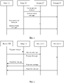
- remote UE needs to discover relay UEs, select one relay UE from the relay UEs, and send a PC5 sidelink (PC5 sidelink, PC5-S) message to the selected relay UE, to trigger establishment of a connection and direct communication between the remote UE and the selected relay UE.
- the remote UE communicates with the network device via the relay UE, to improve data transmission performance.
- the network device may be a base station. An existing manner of discovering relay UE by remote UE is shown in FIG. 1 or FIG. 2 .
- an existing method for discovering relay UE may include: Relay UEs send announcement (announcement) messages to surroundings of the relay UEs. After remote UE monitors (monitors) the announcement messages, the remote UE measures signal quality of the monitored announcement messages, and selects relay UE with better signal quality as relay UE that finally needs to be connected.
- another existing method for discovering relay UE may include: Remote UE sends a request message, for example, solicitation, to surroundings of the remote UE. After monitoring the request message, relay UEs return response (response) messages to the remote UE. The remote UE receives the response messages, measures signal quality of the received response messages, and selects relay UE with better signal quality as relay UE that finally needs to be connected.
- a request message for example, solicitation
- relay UE After monitoring the request message, relay UEs return response (response) messages to the remote UE.
- the remote UE receives the response messages, measures signal quality of the received response messages, and selects relay UE with better signal quality as relay UE that finally needs to be connected.
- a network device broadcasts two thresholds to relay UEs over an air interface. For example, the network device broadcasts a threshold (threshold) 1 and a threshold 2 to the relay UEs, the relay UEs measure air interface signal quality, and only relay UE whose air interface signal quality is within a range of the two thresholds sends the announcement message shown in FIG. 1 or the response message shown in FIG. 2 .
- the network device broadcasts a threshold to a plurality of remote UEs over an air interface. For example, the network device broadcasts a threshold 3 to the remote UEs, the remote UEs measure air interface signal quality, and only remote UE whose air interface signal quality obtained through measurement is lower than the threshold can send the request message shown in FIG. 2 .
- Remote UE obtained through screening may select, according to the method shown in FIG. 1 or FIG. 2 , one relay UE from relay UEs that are obtained through screening based on preset thresholds, establish a connection to the selected relay UE, and communicate with a network device via the relay UE. Screening of the remote UEs and the relay UEs based on the preset thresholds is loose, and information for relay UE selection is relatively limited. Consequently, selection of the relay UE is not accurate enough, and data forwarding performed via the relay UE selected by the remote UE cannot meet a performance requirement of a network system.
- a network device obtains a measurement report that includes signal quality of a sidelink (sidelink, SL) between first user equipment and at least one second user equipment and a radio network identifier of the at least one second user equipment, selects target relay user equipment, of the first user equipment, from the at least one second user equipment based on the measurement report and selection assistance information associated with each second user equipment.
- the network device may select appropriate relay user equipment by comprehensively considering entire-network system performance. Therefore, performance of the selected relay user equipment is better, so that reliability of data transmission performed by remote user equipment via the relay user equipment is improved, and a performance requirement of a network system is improved.
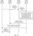
- the method refer to descriptions in the following embodiments corresponding to methods shown in FIG. 5 to FIG. 8A and FIG. 8B .
- the relay communication method provided in embodiments of this application may be applied to a communications system that supports UE cooperation communication, for example, may be applied to any one of a 4 th generation (4 th generation, 4G) system, a long term evolution (long term evolution, LTE) system, a 5th generation (5th generation, 5G) system, anew radio (new radio, NR) system, or an NR vehicle-to-everything (vehicle-to-everything, V2X) system, and may be further applied to another next-generation communications system.
- This is not limited.
- the following uses a communications system shown in FIG. 3 as an example to describe the method provided in embodiments of this application.
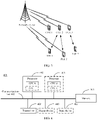
- FIG. 3 is a schematic diagram of a communications system according to an embodiment of this application.
- the communications system may include a network device and a plurality of user equipments.
- the plurality of user equipments may include cooperating user equipments (cooperating UEs, CUEs) and target user equipments (target UEs, TUEs).
- the plurality of user equipments may include CUE 1 to CUE 3 and TUE 1 to TUE 3.
- CUE may be located within coverage of the network device, establishes a wireless connection to the network device, and communicates with the network device over an air interface.
- TUE may be located within coverage of the network device, establishes a wireless connection to the network device, and communicates with the network device over an air interface.
- TUE may establish an SL connection to CUE selected according to the method in embodiments of this application, and communicate with the network device via the CUE. For example, the TUE may send uplink data to the CUE on an SL. After receiving the uplink data, the CUE sends the uplink data to the network device over the air interface. The network device may send downlink data to the CUE. After receiving the downlink data, the CUE sends the downlink data to the TUE on the SL.
- the network device is mainly configured to implement functions such as a physical layer function, resource scheduling and management, and access control and mobility management of a terminal.
- the network device may be a device that supports wired access, or may be a device that supports wireless access.
- the network device may be an access network (access network, AN) device/a radio access network (radio access network, RAN) device, and includes a plurality of 5G-AN/5G-RAN nodes.
- the 5G-AN/5G-RAN node may be an access point (access point, AP), a base station (NodeB, NB), an enhanced base station (enhanced NodeB, eNB), a next-generation base station (NR NodeB, gNB), a transmission reception point (transmission reception point, TRP), a transmission point (transmission point, TP), another access node, or the like.
- an apparatus configured to implement functions of the network device may be the network device, or may be an apparatus, for example, a chip system, that can support the network device in implementing the functions.
- the user equipment may be a terminal device (terminal equipment), a mobile station (mobile station, MS), a mobile terminal (mobile terminal, MT), or the like.
- the terminal may be a mobile phone (mobile phone), a tablet computer, or a computer with a wireless transceiver function, or may be a virtual reality (virtual reality, VR) terminal, an augmented reality (augmented reality, AR) terminal, a wireless terminal in industrial control, a wireless terminal in self-driving, a wireless terminal in telemedicine, a wireless terminal in a smart grid, a wireless terminal in a smart city (smart city), a smart home, a vehicle-mounted terminal, or the like.
- an apparatus configured to implement functions of the CUE or the TUE may be a terminal, or may be an apparatus, for example, a chip system, that can support the terminal in implementing the functions.
- FIG. 3 is merely an example accompanying drawing, and a quantity of nodes included in FIG. 3 is not limited.
- the communications system may further include another node, for example, a core network device, a gateway device, or an application server. This is not limited.
- TUE and CUE in FIG. 3 are example names. Specifically, the TUE may alternatively be named as remote UE, first user equipment, or the like, and the CUE may be named as relay UE, second user equipment, or the like.
- TUE is first user equipment and the CUE is second user equipment is used below to describe the relay communication method provided in embodiments of this application.
- FIG. 4 is a schematic diagram of composition of a communications apparatus 400 according to an embodiment of this application.
- the communications apparatus 400 may be a network device, or a chip or a system-on-a-chip in the network device.
- the communications apparatus 400 may be the user equipment, or a chip or a system-on-a-chip in the user equipment.
- the communications apparatus 400 may include a processor 401, a communications line 402, and a transceiver 403. Further, the communications apparatus 400 may include a memory 404. The processor 401, the memory 404, and the transceiver 403 may be connected to each other through the communications line 402.
- the processor 401 may be a central processing unit (central processing unit, CPU), a general-purpose network processor (network processor, NP), a digital signal processor (digital signal processor, DSP), a microprocessor, a microcontroller, a programmable logic device (programmable logic device, PLD), or any combination thereof.
- the processor 401 may alternatively be any other apparatus having a processing function, for example, a circuit, a component, or a software module.
- the communications line 402 is configured to transmit information between the components included in the communications apparatus 400.
- the transceiver 403 is configured to communicate with another device or another communications network.
- the another communications network may be the Ethernet, a radio access network (radio access network, RAN), a wireless local area network (wireless local area network, WLAN), or the like.
- the transceiver 403 may be a radio frequency module or any apparatus that can implement communication. In embodiments of this application, only an example in which the transceiver 403 is a radio frequency module is used for description.
- the radio frequency module may include an antenna, a radio frequency circuit, and the like.
- the radio frequency circuit may include a radio frequency integrated chip, a power amplifier, and the like.
- the memory 404 is configured to store instructions.
- the instructions may be a computer program.
- the memory 404 may be a read-only memory (read-only memory, ROM) or another type of static storage device that can store static information and/or instructions, or may be a random access memory (random access memory, RAM) or another type of dynamic storage device that can store information and/or instructions, or may be an electrically erasable programmable read-only memory (electrically erasable programmable read-only memory, EEPROM), a compact disc read-only memory (compact disc read-only memory, CD-ROM) or another optical disk storage, an optical disc storage, or a magnetic disk storage medium or another magnetic storage device.
- the optical disc storage includes a compact disc, a laser disc, an optical disc, a digital versatile disc, a Blu-ray disc, and the like.
- the memory 404 may exist independently of the processor 401, or may be integrated into the processor 401.
- the memory 404 may be configured to store instructions, program code, some data, or the like.
- the memory 404 may be located inside the communications apparatus 400, or may be located outside the communications apparatus 400. This is not limited.
- the processor 401 is configured to execute the instructions stored in the memory 404, to implement the relay communication method provided in the following embodiments of this application.
- the processor 401 may include one or more CPUs, for example, a CPU 0 and a CPU 1 in FIG. 4 .
- the communications apparatus 400 includes a plurality of processors.
- the communications apparatus 400 may further include a processor 407 in addition to the processor 401 in FIG. 4 .
- the communications apparatus 400 further includes an output device 405 and an input device 406.
- the input device 406 is a device such as a keyboard, a mouse, a microphone, or a joystick
- the output device 405 is a device such as a display screen or a speaker (speaker).
- the communications apparatus 400 may be a desktop computer, a portable computer, a network server, a mobile phone, a tablet computer, a wireless terminal, an embedded device, a chip system, or a device having a structure similar to that in FIG. 4 .
- the composition structure shown in FIG. 4 does not constitute a limitation on the communications apparatus.
- the communications apparatus may include more or fewer components than those shown in the figure, or some components may be combined, or different component arrangements may be used.
- a chip system may include a chip, or may include a chip and another discrete component.
- FIG. 5 shows a relay communication method according to an embodiment of this application. As shown in FIG. 5 , the method may include the following steps.
- Step 501 A network device obtains a measurement report.
- the network device may be the network device in the system shown in FIG. 3 , or may be a functional module, a chip, a system-on-a-chip, or the like in the network device shown in FIG. 3 . This is not limited.
- the measurement report may include signal quality of a sidelink between first user equipment and at least one second user equipment and a radio network identifier of the at least one second user equipment.
- the first user equipment may be any TUE that is in the system shown in FIG. 3 , or a functional module, a chip, or a system-on-a-chip in the TUE.
- the first user equipment may be located within coverage of the network device, or may not be located within coverage of the network device.
- the at least one second user equipment may be the CUE that is in the system shown in FIG. 3 and that supports direct communication with the first user equipment, or a functional module, a chip, a system-on-a-chip, or the like in the CUE.
- Signal quality of a sidelink between the first user equipment and second user equipment may be determined based on reference signal received power (reference signal received power, RSRP), reference signal received quality (reference signal received quality, RSRQ), a signal to interference plus noise ratio (signal to interference plus noise ratio, SINR), or a received signal strength indicator (received signal strength indicator, RSSI) transmitted on the sidelink.
- reference signal received power reference signal received power
- RSRQ reference signal received quality
- SINR signal to interference plus noise ratio
- RSSI received signal strength indicator
- a radio network identifier of second user equipment may be used by the network device to uniquely identify the second user equipment.
- the radio network identifier of the second user equipment may be configured by the network device for the second user equipment.
- the radio network identifier of the second user equipment may be a radio access network identifier (radio access network identifier, RAN ID), and may include a cell identifier (cell ID) and a cell radio network temporary identifier (cell radio network temporary identifier, C-RANTI).
- Radio network identifiers of different second user equipments are different. For example, as shown in FIG.
- radio network identifiers of the three second user equipments may be a UE ID 1, a UE ID 2, and a UE ID 3, and radio network identifiers of three second user equipments are different.
- the network device may obtain the measurement report in the following Manner (1), Manner (2), or Manner (3).
- Manner (1) The first user equipment obtains the measurement report through measurement, and the network device receives, over an air interface between the network device and the first user equipment, the measurement report reported by the first user equipment.
- Manner (2) The first user equipment obtains the measurement report through measurement, and sends the measurement report to initial relay user equipment.
- the network device receives the measurement report reported by the initial relay user equipment.
- the initial relay user equipment is one second user equipment selected by the first user equipment from the at least one second user equipment, and an SL connection is established between the first user equipment and the initial relay user equipment.
- Manner (3) Each second user equipment measures signal quality of a sidelink between the second user equipment and the first user equipment, and the network device receives the signal quality of the sidelink between the second user equipment and the first user equipment and a radio network identifier of the second user equipment from the second user equipment over an air interface between the network device and the second user equipment.
- the network device receives the signal quality of the sidelink between the second user equipment and the first user equipment and a radio network identifier of the second user equipment from the second user equipment over an air interface between the network device and the second user equipment.
- Step 502 The network device selects target relay user equipment, of the first user equipment, from the at least one second user equipment based on the measurement report and selection assistance information associated with each second user equipment.
- the selection assistance information may include one or more of the following information: subscription information of the second user equipment, air interface signal quality of the second user equipment, air interface signal quality of the first user equipment, load information of the second user equipment, and interference information of the second user equipment.
- the selection assistance information includes the subscription information of the second user equipment.
- the selection assistance information includes the air interface signal quality of the second user equipment.
- the selection assistance information includes the air interface signal quality of the first user equipment.
- the selection assistance information includes the subscription information of the second user equipment, the air interface signal quality of the second user equipment, and the air interface signal quality of the first user equipment.
- the subscription information of the second user equipment may refer to information that the second user equipment subscribes to when the second user equipment accesses a network, and may include a service type supported by the second user equipment, a quality of service (quality of service, QoS) requirement of the second user equipment, and the like.
- the air interface signal quality of the second user equipment may refer to signal quality on the air interface between the second user equipment and the network device, for example, RSRP, RSRQ, an SINR, or an RSSI on the air interface between the second user equipment and the network device.
- an air interface may be referred to as a Uu interface or the like. This is not limited.
- the air interface signal quality of the first user equipment may refer to signal quality on the air interface between the first user equipment and the network device, for example, RSRP, RSRQ, an SINR, or an RSSI on the air interface between the first user equipment and the network device.
- the load information of the second user equipment may include an amount of data forwarded by the second user equipment.
- the interference information of the second user equipment may include information about another user equipment that causes interference to data forwarding performed by the second user equipment.
- the target relay user equipment may be one or more user equipments that are selected by the network device and that are configured to forward data for the first user equipment.
- the selection assistance information includes the air interface signal quality of the second user equipment. That the network device selects target relay user equipment, of the first user equipment, from the at least one second user equipment based on the measurement report and selection assistance information associated with each second user equipment includes: The network device uses, as the target relay user equipment, second user equipment with better air interface signal quality in second user equipments with high sidelink signal quality in the at least one second user equipment.
- the selection assistance information includes the load information of the second user equipment. That the network device selects target relay user equipment, of the first user equipment, from the at least one second user equipment based on the measurement report and selection assistance information associated with each second user equipment includes: The network device uses, as the target relay user equipment, second user equipment with smaller load in second user equipments with high sidelink signal quality in the at least one second user equipment.
- the selection assistance information includes the subscription information of the second user equipment, the air interface signal quality of the second user equipment, the air interface signal quality of the first user equipment, the load information of the second user equipment, and the interference information of the second user equipment.
- the network device uses, as the target relay user equipment, second user equipment with a higher QoS requirement, better air interface signal quality, smaller load, and less interference in second user equipments with high sidelink signal quality in the at least one second user equipment.
- the network device selects the appropriate target relay user equipment based on the signal quality of the SL between the first user equipment and the second user equipment, the selection assistance information associated with each second user equipment, and the like, and notifies the first user equipment of the selected relay user equipment.
- the first user equipment is triggered to establish an SL connection to the selected relay user equipment, and communicates with the network device via the relay user equipment that establishes the SL connection to the first user equipment.
- the network device selects the appropriate relay user equipment based on an entire-network communication status such as a communication status between the first user equipment and the second user equipment and other selection assistance information. Selecting the appropriate relay user equipment by comprehensively considering entire-network system performance improves reliability of data transmission performed by remote user equipment via the relay user equipment, and improves a performance requirement of a network system.
- the method shown in FIG. 3 further includes: The network device obtains a sidelink identifier of each second user equipment, and sends a radio network identifier of the target relay user equipment and/or a sidelink identifier of the target relay user equipment to the first user equipment.
- the first user equipment establishes the SL connection to the target relay user equipment based on the radio network identifier of the target relay user equipment and/or the sidelink identifier of the target relay user equipment, and forwards data via the target relay user equipment. That is, the first user equipment initiates establishment of the SL connection to the target relay user equipment.
- the sidelink identifier of each second user equipment is used for sidelink SL communication between the first user equipment and the second user equipment.
- the sidelink identifier of each second user equipment is used as a target address and is included at a media access control (media access control, MAC) layer of the first user equipment when the first user equipment and the second user equipment establish an SL connection.
- the sidelink identifier of the second user equipment may be referred to as an SL ID or a layer 2 identifier (Layer2 ID).
- a MAC layer data packet sent by the first user equipment includes a sidelink identifier of the first user equipment and the sidelink identifier of the second user equipment.
- the sidelink identifier of the first user equipment is a source address
- the sidelink identifier of the second user equipment is the target address.
- the network device may notify the target relay user equipment to establish the SL connection between the target relay user equipment and the first user equipment.
- the network device may further obtain a radio network identifier of the first user equipment and/or a sidelink identifier of the first user equipment, and send an announcement message including the radio network identifier of the first user equipment and/or the sidelink identifier of the first user equipment to the target relay user equipment, to trigger the target relay user equipment to establish the SL connection to the first user equipment.
- the radio network identifier of the first user equipment is allocated by the network device, and the radio network identifier of the first user equipment is used by the network device to uniquely identify the first user equipment.
- the radio network identifier of the first user equipment is used by the network device to uniquely identify the first user equipment.
- the sidelink identifier of the first user equipment may be used for SL communication between the first user equipment and the at least one second user equipment.
- the sidelink identifier of the first user equipment is used as a target address and is included in a MAC layer of second user equipment when the first user equipment and the second user equipment establish an SL connection.
- the sidelink identifier of the first user equipment may also be referred to as an SL ID or a layer 2 identifier (Layer2 ID), and the sidelink identifier of the first user equipment is different from a sidelink identifier of second user equipment.
- the method shown in FIG. 3 further includes: The network device sends, to the target relay user equipment, group scheduling information used to schedule data of communication between the first user equipment and the network device, so that the target relay user equipment monitors a corresponding G-RNTI on a time domain resource and a frequency domain resource that are indicated by time-frequency domain information, and receives the data sent by the network device to the first user equipment.
- the group scheduling information includes the G-RNTI for group scheduling and the time-frequency domain information for group scheduling.
- the G-RNTI may be used to scramble the data sent by the network device to the first user equipment.
- the time-frequency domain information may be used to indicate the time domain resource, the frequency domain resource, or the like occupied by the data sent by the network device to the first user equipment.
- FIG. 6 shows a relay communication method according to an embodiment of this application.
- First user equipment sends a measurement report to a network device over an air interface.
- the method may include the following steps.
- Step 601 The first user equipment sends discovery request (discovery request) messages to a plurality of second user equipments through broadcast.
- the first user equipment and each second user equipment may be UE preconfigured or specified by a network for UE cooperation communication.
- the first user equipment may be any TUE that is in the system shown in FIG. 3 , or a functional module, a chip, or a system-on-a-chip in the TUE.
- the first user equipment may be located within coverage of the network device.
- the second user equipment may be the CUE that is in the system shown in FIG. 3 and that supports direct communication with the first user equipment, or a functional module, a chip, a system-on-a-chip, or the like in the CUE.
- the first user equipment may be the TUE 1, the TUE 2, or the TUE 3 in FIG.
- the plurality of second user equipments may include the CUE 1, the CUE 2, and the CUE 3 in FIG. 3 . It should be noted that a quantity of second user equipments is not limited in this application. There may be two, three, or more second user equipments. This is not limited.
- the discovery request message may be replaced with a solicitation message, and the discovery request message may be used to discover relay UEs around the first user equipment.
- the first user equipment may send the discovery request messages to the plurality of second user equipments when a trigger condition is met. In other words, the first user equipment sends the discovery request messages to the plurality of second user equipments once the trigger condition is met.
- the trigger condition may include that signal quality on the air interface between the first user equipment and the network device is less than or equal to a first threshold.
- the first threshold may be set as required. When the signal quality on the air interface between the first user equipment and the network device is less than or equal to the first threshold, it indicates that quality on the air interface between the first user equipment and the network device is poor, and it is not suitable to transmit data over the air interface. When the signal quality on the air interface between the first user equipment and the network device is greater than the first threshold, it indicates that quality on the air interface between the first user equipment and the network device is good, and data may be directly transmitted to the network device over the air interface.
- the trigger condition may be configured by the network device for the first user equipment before step 601 is performed.
- the first user equipment receives a radio resource control (radio resource control, RRC) message from the network device, where the RRC message carries the trigger condition, and the first user equipment obtains the trigger condition from the RRC message.
- RRC radio resource control
- the trigger condition may alternatively be named as a CUE discovery configuration, another name, or the like. This is not limited.
- Step 602 Each second user equipment receives the discovery request message, and sends a response message to the first user equipment.
- the response message corresponds to the discovery request message, and the response message may be used to indicate that the second user equipment is around the first user equipment.
- the response message may include a radio network identifier of the second user equipment, and may further include a sidelink identifier of the second user equipment and other information. This is not limited.
- the radio network identifier of the second user equipment may be configured by the network device for the second user equipment before the method shown in FIG. 6 is performed. For example, before step 602 is performed, the second user equipment receives an RRC message from the network device, where the RRC message carries the radio network identifier of the second user equipment. The second user equipment obtains the radio network identifier of the second user equipment from the RRC message, includes the radio network identifier of the second user equipment in the response message, and sends the response message to the first user equipment.
- the second user equipment may send the response message to the first user equipment in a unicast manner.
- Step 603 The first user equipment receives the response message sent by each second user equipment, and measures the response message sent by the second user equipment, to obtain signal quality of a sidelink between the first user equipment and the second user equipment.
- the first user equipment may measure one or more types of information such as RSRP, RSRQ, an SINR, or an RSSI of the response message sent by the second user equipment, to obtain the signal quality of the sidelink between the first user equipment and the second user equipment.
- RSRP is used as an example. If the RSRP of the response message is large, the signal quality of the sidelink between the first user equipment and the second user equipment is high. Alternatively, if the RSRP of the response message is small, the signal quality of the sidelink between the first user equipment and the second user equipment is low.
- Step 604 The first user equipment sends the measurement report to the network device.
- the measurement report may include signal quality of the response messages sent by the plurality of second user equipments and radio network identifiers of the plurality of second user equipments, and may further include other information such as a sidelink identifier of the first user equipment and sidelink identifiers of the second user equipments. This is not limited.
- the signal quality of the sidelink between the first user equipment and the second user equipment and the radio network identifier of the second user equipment are correspondingly included in the measurement report.
- the signal quality of the sidelink between the first user equipment and the second user equipment and the radio network identifier of the second user equipment may be correspondingly included in the measurement report in an array form.
- the measurement report may be ⁇ UE ID 1, signal quality of a sidelink between the first user equipment and the CUE 1 ⁇ , ⁇ UE ID 2, signal quality of a sidelink between the first user equipment and the CUE 2 ⁇ , and ⁇ UE ID 3, signal quality of a sidelink between the first user equipment and the CUE 3 ⁇ .
- the first user equipment may send the measurement report to the network device over the air interface.
- the first user equipment may select one second user equipment from the plurality of second user equipments as initial relay user equipment, establish an SL connection to the initial relay user equipment, and send the measurement report to the initial relay user equipment on an SL, so that the initial relay user equipment sends the measurement report to the network device over an air interface.
- the initial relay user equipment sends the measurement report to the network device over an air interface.
- the first user equipment may use, based on the signal quality of the response messages sent by the plurality of second user equipments, second user equipment that sends a response message with higher signal quality as the initial relay user equipment, or may randomly select one second user equipment from the plurality of second user equipments as the initial relay user equipment. This is not limited.
- Step 605 The network device receives the measurement report, and selects target relay user equipment, of the first user equipment, from the plurality of second user equipments based on the measurement report and selection assistance information associated with each second user equipment.
- step 605 refer to step 502. Details are not described again.
- Step 606 The network device sends a radio network identifier of the target relay user equipment to the first user equipment.
- the network device when the first user equipment sends the measurement report to the network device over the air interface, the network device sends the radio network identifier of the target relay user equipment to the first user equipment over the air interface.
- the network device may send the radio network identifier of the target relay user equipment to the first user equipment via the initial relay user equipment, or may directly send the radio network identifier of the target relay user equipment to the first user equipment over the air interface.
- the measurement report includes the sidelink identifiers of the plurality of second user equipments
- the network device may further send a sidelink identifier of the target relay user equipment to the first user equipment, so that the first user equipment establishes an SL connection to the target relay user equipment based on the sidelink identifier of the target relay user equipment.
- Step 607 The first user equipment receives the radio network identifier of the target relay user equipment, establishes the SL connection to the target relay user equipment, and communicates with the network device via the target relay user equipment.
- the first user equipment When the first user equipment establishes the SL connection to the initial relay user equipment and sends the measurement report to the network device via the initial relay user equipment, if the target relay user equipment finally selected by the network device is the same as the initial relay user equipment, the first user equipment still maintains the SL connection between the first user equipment and the initial relay user equipment, and communicates with the network device via the initial relay user equipment. Alternatively, if the target relay user equipment finally selected by the network device is different from the initial relay user equipment, the first user equipment releases/breaks the SL connection between the first user equipment and the initial relay user equipment, establishes the SL connection to the target relay user equipment through an existing SL establishment procedure, and communicates with the network device via the target relay user equipment.
- the first user equipment is the TUE 2 in FIG. 3
- the plurality of second user equipments are the CUE 1 to the CUE 3 in FIG. 3 .
- the TUE 2 selects the CUE 2 from the CUE 1 to the CUE 3 as the initial relay user equipment, establishes an SL connection to the CUE 2, and sends the measurement report to the network device via the CUE 2.
- the TUE 2 finally needs to communicate with the network device via the CUE 1, after receiving a selection result of the network device, the TUE 2 releases the SL connection between the TUE 2 and the CUE 2, establishes an SL connection to the CUE 1, and communicates with the network device via the CUE 1.
- the TUE 2 If the network device selects the CUE 2 from the CUE 1 to the CUE 3 as the target relay user equipment, in other words, the TUE 2 finally needs to communicate with the network device via the CUE 2, after receiving a selection result of the network device, the TUE 2 maintains the SL connection between the TUE 2 and the CUE 2, and communicates with the network device via the CUE 2.
- the method further includes: The network device sends group scheduling information to the target relay user equipment.
- the network device selects the appropriate relay user equipment based on the signal quality of the SL between the first user equipment and the second user equipment, other selection assistance information, and the like, and notifies the first user equipment of the selected relay user equipment.
- the first user equipment is triggered to establish the SL connection to the selected relay user equipment, and communicates with the network device via the relay user equipment that establishes an SL to the first user equipment.
- the network device selects the appropriate relay user equipment based on an entire-network communication status, to improve reliability of data transmission performed by remote user equipment via the relay user equipment, and improve a performance requirement of a network system.
- first user equipment selects initial relay user equipment and sends a measurement report to a network device via the initial relay user equipment.
- FIG. 7A and FIG. 7B show a relay communication method according to an embodiment of this application. As shown in FIG. 7A and FIG. 7B , the method may include the following steps.
- Step 701 A network device configures radio network identifiers for first user equipment and second user equipment that can be used for UE cooperation communication.
- radio network identifier of the first user equipment and the radio network identifier of the second user equipment, refer to the descriptions in the embodiment corresponding to FIG. 5 . Details are not described again.
- Step 702 The network device configures a trigger condition for the first user equipment.
- the network device may configure the trigger condition for the first user equipment based on an RRC message.
- the network device may send the RRC message to the first user equipment, where the RRC message may carry the trigger condition.
- Step 703 When the trigger condition is met, the first user equipment sends discovery request messages to a plurality of second user equipments.
- step 703 refer to step 601. Details are not described again.
- Step 704 The second user equipments receive the discovery request messages, and return response messages to the first user equipment.
- step 704 refer to step 602. Details are not described again.
- Step 705 The first user equipment receives the response messages returned by the plurality of second user equipments, and measures the response message returned by each second user equipment, to obtain signal quality of a sidelink between the first user equipment and the second user equipment.
- step 705 refer to step 603. Details are not described again.
- Step 706 The first user equipment selects initial relay user equipment from the plurality of second user equipments based on the signal quality obtained through measurement.
- the initial relay user equipment may be second user equipment 3 in FIG. 7A and FIG. 7B .
- the first user equipment may randomly select one second user equipment from the plurality of second user equipments as the initial relay user equipment, or may select second user equipment with better signal quality as the initial relay user equipment.
- Step 707 The first user equipment establishes an SL connection to the initial relay user equipment, and sends a measurement report to the network device via the initial relay user equipment.
- the first user equipment sends a measurement report to the network device via the initial relay user equipment may include: The first user equipment sends the measurement report to the initial relay user equipment on an SL, and the initial relay user equipment receives the measurement report, and sends the measurement report to the network device over an air interface.
- Step 708 The network device receives the measurement report, and selects target relay user equipment from the plurality of second user equipments based on the measurement report and selection assistance information.
- the target relay user equipment may be second user equipment 1 in FIG. 7A and FIG. 7B .
- step 708 refer to step 604. Details are not described again.
- Step 709 The network device sends group scheduling information to the second user equipment 1.
- Step 710 The network device sends a radio network identifier of the second user equipment 1 to the first user equipment.
- step 710 refers to step 605. Details are not described again.
- step 709 and step 710 are not limited in this embodiment of this application.
- Step 709 may be performed first, or step 710 may be performed first, or step 710 may be performed before step 709, or step 709 and step 710 may be simultaneously performed. This is not limited.
- Step 711 The first user equipment receives the radio network identifier of the second user equipment 1, releases the SL connection between the first user equipment and the second user equipment 3, establishes an SL connection to the second user equipment 1, and communicates with the network device via the second user equipment 1.
- step 711 refers to step 606. Details are not described again.
- the first user equipment may send, to the network device via relay user equipment autonomously selected by the first user equipment, the measurement report that includes signal quality of sidelinks between the first user equipment and the plurality of second user equipments.
- the network device selects the appropriate relay user equipment based on the measurement report, other selection assistance information, and the like, and notifies the first user equipment of the selected relay user equipment.
- the first user equipment is triggered to establish the SL connection to the selected relay user equipment, and subsequently communicates with the network device via the relay user equipment that establishes the SL connection to the first user equipment.
- the network device selects the appropriate relay user equipment based on an entire-network communication status, to improve reliability of data transmission performed by remote UE via the relay user equipment, and improve a performance requirement of a network system.
- FIG. 6 , FIG. 7A , and FIG. 7B are described merely by using an example in which the first user equipment sends the measurement report to the network device.
- the second user equipments may report signal quality of sidelinks between the second user equipments and the first user equipment to the network device, so that the network device selects the appropriate relay user equipment based on selection assistance information and the signal quality of the sidelinks that is reported by the plurality of second user equipments.
- FIG. 8A and FIG. 8B refer to FIG. 8A and FIG. 8B .
- FIG. 8A and FIG. 8B show a relay communication method according to an embodiment of this application. As shown in FIG. 8A and FIG. 8B , the method may include the following steps.
- Step 801 A network device configures radio network identifiers for first user equipment and second user equipment that can be used for UE cooperation communication.
- step 801 refer to step 701. Details are not described again.
- Step 802 The network device configures a trigger condition for the first user equipment.
- step 802 refer to step 702. Details are not described again.
- Step 803 When the trigger condition is met, the first user equipment sends discovery request messages to a plurality of second user equipments.
- step 803 refer to step 703. Details are not described again.
- Step 804 Each second user equipment receives the discovery request message, and measures the discovery request message sent by the first user equipment, to obtain signal quality of a sidelink between the first user equipment and the second user equipment.
- the second user equipment may measure one or more types of information such as RSRP, RSRQ, an SINR, or an RSSI of the discovery request message sent by the first user equipment, to obtain the signal quality of the sidelink between the first user equipment and the second user equipment.
- RSRP is used as an example. If the RSRP of the discovery request message is large, the signal quality of the sidelink between the first user equipment and the second user equipment is high. Alternatively, if the RSRP of the discovery request message is small, the signal quality of the sidelink between the first user equipment and the second user equipment is low.
- Step 805 Each second user equipment sends the signal quality of the sidelink between the second user equipment and the first user equipment to the network device. Further, the second user equipment sends a sidelink identifier of the second user equipment to the network device.
- Step 806 The network device receives the signal quality that is of the sidelink between each second user equipment and the first user equipment and that is sent by the second user equipment, and selects target relay user equipment, for example, second user equipment 1, from the plurality of second user equipments based on signal quality of sidelinks between the plurality of second user equipments and the first user equipment and selection assistance information.
- target relay user equipment for example, second user equipment 1
- the network device selects target relay user equipment refer to step 607 in FIG. 6 . Details are not described again.
- Step 807 The network device sends group scheduling information to the second user equipment 1.
- Step 808 The network device sends an announcement message to the second user equipment 1.
- the announcement message may be used to notify or trigger the second user equipment 1 to establish an SL connection between the second user equipment 1 and the first user equipment.
- step 807 and step 808 are not limited in this embodiment of this application.
- Step 807 may be performed first, or step 808 may be performed first, or step 808 may be performed before step 807, or step 807 and step 808 may be simultaneously performed. This is not limited.
- Step 809 The second user equipment 1 establishes the SL connection to the first user equipment.
- the first user equipment may communicate with the network device via the second user equipment 1.
- the plurality of second user equipments may send, to the network device, the measurement report that includes the signal quality of the sidelinks between the first user equipment and the second user equipments.
- the network device selects the appropriate relay user equipment based on the signal quality of the sidelinks between the first user equipment and the plurality of second user equipments, other selection assistance information, and the like, and notifies the first user equipment of the selected relay user equipment.
- the first user equipment is triggered to establish the SL connection to the selected relay user equipment, and subsequently communicates with the network device via the relay user equipment that establishes the SL connection to the first user equipment.
- the network device selects the appropriate relay user equipment based on an entire-network communication status, to improve reliability of data transmission performed by remote UE via the relay user equipment, and improve a performance requirement of a network system.
- the communications apparatuses such as the network device, the first user equipment, and the second user equipment include corresponding hardware structures and/or software modules for performing the functions.
- the communications apparatuses such as the network device, the first user equipment, and the second user equipment include corresponding hardware structures and/or software modules for performing the functions.
- this application can be implemented by hardware or a combination form of hardware and computer software. Whether a function is performed by hardware or hardware driven by computer software depends on particular applications and design constraints of the technical solutions. A person skilled in the art may use different methods to implement the described functions for each particular application, but it should not be considered that the implementation goes beyond the scope of this application.
- each functional module may be obtained through division corresponding to each function, or two or more functions may be integrated into one processing module.
- the integrated module may be implemented in a form of hardware, or may be implemented in a form of a software functional module. It should be noted that, in embodiments of this application, division into the modules is an example, and is merely a logical function division. In actual implementation, another division manner may be used.
- FIG. 9 is a diagram of a structure of a communications apparatus 90.
- the communications apparatus 90 may be a network device, or a chip or a system-on-a-chip in the network device.
- the communications apparatus 90 may be configured to perform functions of the network device in the foregoing embodiments.
- the communications apparatus 90 shown in FIG. 9 includes an obtaining unit 901 and a selection unit 902.
- the obtaining unit 901 is configured to obtain a measurement report that includes signal quality of an SL between first user equipment and at least one second user equipment and a radio network identifier of the at least one second user equipment.
- the obtaining unit 901 may support the communications apparatus 90 in performing step 501, step 605, step 708, and step 806.
- the selection unit 902 is configured to select target relay user equipment, of the first user equipment, from the at least one second user equipment based on the measurement report and selection assistance information associated with each second user equipment.
- the selection unit may support the communications apparatus 90 in performing step 502, step 605, step 708, and step 806.
- the obtaining unit 901 and the selection unit 902 in FIG. 9 may be replaced with a processor, and functions of the obtaining unit 901 and the selection unit 902 may be integrated into the processor.
- the communications apparatus 90 shown in FIG. 9 may further include a memory.
- the communications apparatus 90 in this embodiment of this application may be the communications apparatus shown in FIG. 4 .
- FIG. 10 is a diagram of a structure of a communications apparatus 100.
- the communications apparatus 100 may be second user equipment, or a chip or a system-on-a-chip in the second user equipment.
- the communications apparatus 100 may be configured to perform functions of the second user equipment in the foregoing embodiments.
- the communications apparatus 100 shown in FIG. 10 includes a sending unit 1001, a receiving unit 1002, and an establishment unit 1003.
- the sending unit 1001 is configured to send a measurement report that includes signal quality of a sidelink between first user equipment and at least one second user equipment and a radio network identifier of the at least one second user equipment to a network device.
- the sending unit 1001 may support the communications apparatus 100 in performing step 604 and step 707.
- the receiving unit 1002 is configured to receive a radio network identifier of target relay user equipment from the network device, where the target relay user equipment is one second user equipment selected from the at least one second user equipment.
- the receiving unit 1002 may support the communications apparatus 100 in performing step 606, step 709, and step 807.
- the establishment unit 1003 is configured to: establish a sidelink SL connection to the target relay user equipment based on the radio network identifier of the target relay user equipment, and communicate with the network device via the target relay user equipment.
- the establishment unit 1003 may be configured to support the communications apparatus 100 in performing step 607, step 711, and step 809.
- the communications apparatus 100 refers to behavior functions of the second user equipment in the relay communication method shown in FIG. 6 or FIG. 8A and FIG. 8B .
- the sending unit 1001 and the receiving unit 1002 in FIG. 10 may be replaced with a transceiver or a transceiver unit, and functions of the sending unit 1001 and the receiving unit 1002 may be integrated into the transceiver.
- the communications apparatus 100 shown in FIG. 10 may further include a processor and a memory.
- the communications apparatus 100 in this embodiment of this application may be the communications apparatus shown in FIG. 4 .
- FIG. 11 is a diagram of a structure of a communications apparatus 110.
- the communications apparatus 110 may be second user equipment, or a chip or a system-on-a-chip in the second user equipment.
- the communications apparatus 110 may be configured to perform functions of the second user equipment in the foregoing embodiments.
- the communications apparatus 110 shown in FIG. 11 includes a receiving unit 1101, a measurement unit 1102, and a sending unit 1103.
- the receiving unit 1101 is configured to receive a discovery request message from first user equipment.
- the receiving unit 1101 may support the communications apparatus 110 in performing step 803.
- the measurement unit 1102 is configured to obtain signal quality of a sidelink between the communications apparatus 110 and the first user equipment through measurement based on the discovery request message.
- the measurement unit 1102 may support the communications apparatus 110 in performing step 804.
- the sending unit 1103 is configured to send, to a network device, the signal quality of the sidelink between the second user equipment and the first user equipment and a radio network identifier that is of the second user equipment and that is used by the network device to uniquely identify the second user equipment.
- the sending unit 1103 may support the communications apparatus 110 in performing step 805.
- the communications apparatus 110 refers to behavior functions of the second user equipment in the relay communication method shown in FIG. 6 or FIG. 8A and FIG. 8B .
- the sending unit 1103 and the receiving unit 1101 in FIG. 11 may be replaced with a transceiver or a transceiver unit, and functions of the sending unit 1101 and the receiving unit 1103 may be integrated into the transceiver.
- the communications apparatus 110 shown in FIG. 11 may further include a processor and a memory.
- the communications apparatus 110 in this embodiment of this application may be the communications apparatus shown in FIG. 4 .
- FIG. 12 is a diagram of a structure of a communications system according to an embodiment of this application. As shown in FIG. 12 , the system may include first user equipment 120, second user equipment 121, and a network device 122.
- the network device 122 has a function of the communications apparatus 90 shown in FIG. 9 .
- the first user equipment 120 has a function of the communications apparatus 100 shown in FIG. 10 .
- the second user equipment 121 has a function of the communications apparatus 110 shown in FIG. 11 . Details are not described again.
- An embodiment of this application further provides a computer-readable storage medium. All or some of the processes in the foregoing method embodiments may be completed by a computer program instructing related hardware.
- the program may be stored in the foregoing computer-readable storage medium. When the program is executed, the processes of the foregoing method embodiments may be performed.
- the computer-readable storage medium may be an internal storage unit of the communications apparatus (including a data transmit end and/or a data receive end) in any one of the foregoing embodiments, for example, a hard disk or a memory of the communications apparatus.
- the computer-readable storage medium may be an external storage device of the communications apparatus, for example, a plug-in hard disk, a smart media card (smart media card, SMC), a secure digital (secure digital, SD) card, or a flash card (flash card) that is configured on the communications apparatus.
- the computer-readable storage medium may alternatively include both the internal storage unit and the external storage device of the communications apparatus.
- the computer-readable storage medium is configured to store the computer program, and other programs and data that are required by the communications apparatus.
- the computer-readable storage medium may be further configured to temporarily store data that has been output or is to be output.
- At least one (item) means one or more
- a plurality of' means two or more
- at least two (items) means two, three, or more.
- the term “and/or” is used to describe an association relationship between associated objects, and indicates that three relationships may exist. For example, “A and/or B” may indicate the following three cases: Only A exists, only B exists, and both A and B exist, where A and B may be singular or plural.
- the character “/” generally indicates an “or” relationship between the associated objects.
- At least one of the following” or similar expressions indicate any combination of the following, including one or any combination of two or more of the following.
- At least one of a, b, or c may indicate: a, b, c, "a and b", “a and c", “b and c", or "a, b and c", where a, b, and c each may be singular or plural.
- the disclosed apparatuses and methods may be implemented in other manners.
- the described apparatus embodiments are merely examples.
- division into the modules or units is merely logical function division.
- a plurality of units or components may be combined or may be integrated into another apparatus, or some features may be ignored or not be performed.
- the displayed or discussed mutual coupling or direct coupling or communication connection may be implemented through some interfaces.
- the indirect coupling or communication connection between the apparatuses or units may be implemented in electrical, mechanical, or another form.
- the units described as separate parts may or may not be physically separate, and parts displayed as units may be one or more physical units, in other words, may be located in one place, or may be distributed on different places. Some or all of the units may be selected based on an actual requirement to achieve the objectives of the solutions in embodiments.
- functional units in embodiments of this application may be integrated into one processing unit, or each of the units may exist alone physically, or two or more units may be integrated into one unit.
- the integrated unit may be implemented in a form of hardware, or may be implemented in a form of a software functional unit.
- the integrated unit When the integrated unit is implemented in the form of a software functional unit and sold or used as an independent product, the integrated unit may be stored in a readable storage medium.
- the technical solutions in embodiments of this application essentially, or the part contributing to a conventional technology, or all or some of the technical solutions may be implemented in a form of a software product.
- the software product is stored in a storage medium and includes several instructions for instructing a device (which may be a single-chip microcomputer, a chip, or the like) or a processor (processor) to perform all or some of the steps of the methods described in embodiments of this application.
- the foregoing storage medium includes: any medium that can store program code, such as a USB flash drive, a removable hard disk, a ROM, a RAM, a magnetic disk, or an optical disc.
- program code such as a USB flash drive, a removable hard disk, a ROM, a RAM, a magnetic disk, or an optical disc.
Landscapes
- Engineering & Computer Science (AREA)
- Computer Networks & Wireless Communication (AREA)
- Signal Processing (AREA)
- Quality & Reliability (AREA)
- Databases & Information Systems (AREA)
- Computer Security & Cryptography (AREA)
- Mobile Radio Communication Systems (AREA)
Applications Claiming Priority (2)
| Application Number | Priority Date | Filing Date | Title |
|---|---|---|---|
| CN201911400008.6A CN113133047B (zh) | 2019-12-30 | 2019-12-30 | 一种中继通信方法及装置 |
| PCT/CN2020/138130 WO2021136007A1 (zh) | 2019-12-30 | 2020-12-21 | 一种中继通信方法及装置 |
Publications (2)
| Publication Number | Publication Date |
|---|---|
| EP4072200A1 true EP4072200A1 (de) | 2022-10-12 |
| EP4072200A4 EP4072200A4 (de) | 2023-05-31 |
Family
ID=76687366
Family Applications (1)
| Application Number | Title | Priority Date | Filing Date |
|---|---|---|---|
| EP20909581.9A Pending EP4072200A4 (de) | 2019-12-30 | 2020-12-21 | Relaiskommunikationsverfahren und -vorrichtung |
Country Status (4)
| Country | Link |
|---|---|
| US (1) | US12418944B2 (de) |
| EP (1) | EP4072200A4 (de) |
| CN (1) | CN113133047B (de) |
| WO (1) | WO2021136007A1 (de) |
Families Citing this family (14)
| Publication number | Priority date | Publication date | Assignee | Title |
|---|---|---|---|---|
| WO2022067715A1 (en) * | 2020-09-30 | 2022-04-07 | Qualcomm Incorporated | Relay selection and re-selection assisted by discovery information |
| CN113873600B (zh) * | 2021-11-22 | 2024-05-03 | Oppo广东移动通信有限公司 | 侧行链路的切换方法、装置、终端、存储介质及程序产品 |
| WO2023115368A1 (en) * | 2021-12-22 | 2023-06-29 | Qualcomm Incorporated | User equipment selection for user equipment cooperation |
| TWI838072B (zh) * | 2022-01-10 | 2024-04-01 | 聯發科技股份有限公司 | 用於中繼節點配置的方法及其使用者設備 |
| WO2023184465A1 (en) * | 2022-04-01 | 2023-10-05 | Qualcomm Incorporated | Ue discovery for ue cooperation |
| JP7779408B2 (ja) * | 2022-04-21 | 2025-12-03 | 1Finity株式会社 | ネットワーク装置とレピータとの間の通信方法及び装置 |
| US12356388B2 (en) * | 2022-06-03 | 2025-07-08 | Qualcomm Incorporated | Network coding with user equipment cooperation |
| CN117560649A (zh) * | 2022-08-05 | 2024-02-13 | 华为技术有限公司 | 一种通信方法、装置和系统 |
| WO2024065452A1 (zh) * | 2022-09-29 | 2024-04-04 | 北京小米移动软件有限公司 | 多路径通信方法、装置及系统 |
| CN115997471A (zh) * | 2022-11-01 | 2023-04-21 | 北京小米移动软件有限公司 | 一种用户设备ue选择或重选方法、装置、设备及存储介质 |
| GB2627358A (en) * | 2023-02-07 | 2024-08-21 | Samsung Electronics Co Ltd | Improvements in and relating to a telecommunication system |
| US20240276297A1 (en) * | 2023-02-10 | 2024-08-15 | Qualcomm Incorporated | Compute offloading for distributed processing |
| TW202529473A (zh) * | 2024-01-12 | 2025-07-16 | 聚眾聯合科技股份有限公司 | 網路連線模組及其選擇橋接點之方法 |
| CN121126484A (zh) * | 2024-06-11 | 2025-12-12 | 中国电信股份有限公司技术创新中心 | 通信方法、系统、用户设备、存储介质和产品 |
Family Cites Families (14)
| Publication number | Priority date | Publication date | Assignee | Title |
|---|---|---|---|---|
| US8605684B2 (en) * | 2010-01-08 | 2013-12-10 | Blackberry Limited | System and method for coordinated multi-point network operation to reduce radio link failure |
| US9439176B2 (en) * | 2014-02-10 | 2016-09-06 | Huawei Technologies, Co., Ltd. | System and method for virtual multi-point transceivers |
| CN106211026B (zh) * | 2014-12-22 | 2019-05-24 | 中兴通讯股份有限公司 | 一种实现设备直通中继选择的方法、网络控制节点及用户设备 |
| US10492120B2 (en) * | 2015-03-31 | 2019-11-26 | Ntt Docomo, Inc. | User apparatus and base station |
| WO2016163733A1 (en) * | 2015-04-06 | 2016-10-13 | Lg Electronics Inc. | Method and apparatus for transmitting relay request indication in wireless communication system |
| JP6985152B2 (ja) * | 2015-04-08 | 2021-12-22 | インターデイジタル パテント ホールディングス インコーポレイテッド | デバイスツーデバイス(d2d)通信のモバイル中継器の実現 |
| WO2016179832A1 (zh) * | 2015-05-14 | 2016-11-17 | 富士通株式会社 | 中继选择或重选方法、装置和系统 |
| EP3273745B1 (de) * | 2015-05-15 | 2020-12-09 | Huawei Technologies Co., Ltd. | Verfahren und system zur relaisauswahl in einer vorrichtung-zu-vorrichtung-kommunikation |
| CN106470382A (zh) * | 2015-08-14 | 2017-03-01 | 中兴通讯股份有限公司 | 授权验证方法、配置信息接收方法、装置、基站及终端 |
| EP3357296B1 (de) * | 2015-10-01 | 2022-05-11 | Sony Group Corporation | Telekommunikationsvorrichtungen und -verfahren |
| US10439682B2 (en) * | 2016-08-19 | 2019-10-08 | FG Innovation Company Limited | Access mechanism for proximity-based service UE-to-network relay service |
| CN116133097A (zh) * | 2017-04-28 | 2023-05-16 | Oppo广东移动通信有限公司 | 一种d2d通信的方法、远程用户设备及中继用户设备 |
| US10912114B2 (en) * | 2017-05-05 | 2021-02-02 | Qualcomm Incorporated | Relaying in a device-to-device communication system |
| CN110461020A (zh) * | 2019-08-16 | 2019-11-15 | 展讯通信(上海)有限公司 | 用于辅链路的中继选择方法及装置、存储介质、终端 |
-
2019
- 2019-12-30 CN CN201911400008.6A patent/CN113133047B/zh active Active
-
2020
- 2020-12-21 EP EP20909581.9A patent/EP4072200A4/de active Pending
- 2020-12-21 WO PCT/CN2020/138130 patent/WO2021136007A1/zh not_active Ceased
-
2022
- 2022-06-28 US US17/851,725 patent/US12418944B2/en active Active
Also Published As
| Publication number | Publication date |
|---|---|
| US12418944B2 (en) | 2025-09-16 |
| EP4072200A4 (de) | 2023-05-31 |
| US20220330362A1 (en) | 2022-10-13 |
| WO2021136007A1 (zh) | 2021-07-08 |
| CN113133047A (zh) | 2021-07-16 |
| CN113133047B (zh) | 2025-02-07 |
Similar Documents
| Publication | Publication Date | Title |
|---|---|---|
| US12418944B2 (en) | Relay communication method and communications apparatus | |
| EP3836688B1 (de) | Ressourcenkonfigurationsverfahren und -vorrichtung | |
| JP6285033B2 (ja) | デバイスツーデバイス通信のためのユーザ装置、コンピュータプログラム、記憶媒体及び通信方法 | |
| KR102255879B1 (ko) | 승인 면제 자원 할당 방법, 사용자 기기 및 네트워크 장치 | |
| US20210258922A1 (en) | Resource configuration method and apparatus | |
| US20220312517A1 (en) | D2d communication method, apparatus, and system | |
| US20240022994A1 (en) | Relay communication method and apparatus | |
| CN105554916A (zh) | 通信网络中的分布式天线系统 | |
| US20170094495A1 (en) | Method for supporting proximity-based service configuring for ue | |
| JP7305872B2 (ja) | 能力シグナリングの方法、無線装置及びネットワークノード | |
| US12213197B2 (en) | Communication method, communications apparatus, and storage medium | |
| JP7626798B2 (ja) | 通信方法及び通信装置 | |
| US20230171658A1 (en) | Communication method and apparatus | |
| CN109691166B (zh) | 无线通信网络中的相邻网络节点的识别 | |
| JP2025502822A (ja) | ダウンリンク送信方法および装置 | |
| CN121056956A (zh) | 无线通信的方法及设备 | |
| CN114258156B (zh) | 业务数据传输方法及装置、终端和基站 | |
| CN103220075B (zh) | 小区能力信息的交互方法、设备和系统 | |
| KR20210076983A (ko) | 직접 통신 자원의 할당 방법 및 장치 | |
| CN115567908B (zh) | 一种通信的方法、装置和系统 | |
| US20240406763A1 (en) | Communication method, terminal, communications device, and network device | |
| US20260025680A1 (en) | Method and device for wireless communication | |
| US20250184090A1 (en) | Communication method and apparatus | |
| WO2025148051A1 (zh) | 一种基于环境物联网的通信方法、通信系统及存储介质 | |
| WO2024152197A1 (zh) | 侧行传输方法及终端设备 |
Legal Events
| Date | Code | Title | Description |
|---|---|---|---|
| STAA | Information on the status of an ep patent application or granted ep patent |
Free format text: STATUS: THE INTERNATIONAL PUBLICATION HAS BEEN MADE |
|
| PUAI | Public reference made under article 153(3) epc to a published international application that has entered the european phase |
Free format text: ORIGINAL CODE: 0009012 |
|
| STAA | Information on the status of an ep patent application or granted ep patent |
Free format text: STATUS: REQUEST FOR EXAMINATION WAS MADE |
|
| 17P | Request for examination filed |
Effective date: 20220708 |
|
| AK | Designated contracting states |
Kind code of ref document: A1 Designated state(s): AL AT BE BG CH CY CZ DE DK EE ES FI FR GB GR HR HU IE IS IT LI LT LU LV MC MK MT NL NO PL PT RO RS SE SI SK SM TR |
|
| DAV | Request for validation of the european patent (deleted) | ||
| DAX | Request for extension of the european patent (deleted) | ||
| A4 | Supplementary search report drawn up and despatched |
Effective date: 20230502 |
|
| RIC1 | Information provided on ipc code assigned before grant |
Ipc: H04W 76/14 20180101ALI20230424BHEP Ipc: H04W 40/22 20090101AFI20230424BHEP |
|
| STAA | Information on the status of an ep patent application or granted ep patent |
Free format text: STATUS: EXAMINATION IS IN PROGRESS |
|
| 17Q | First examination report despatched |
Effective date: 20250811 |
|
| REG | Reference to a national code |
Ref country code: DE Ref legal event code: R079 Free format text: PREVIOUS MAIN CLASS: H04W0040220000 Ipc: H04W0016260000 |
|
| GRAP | Despatch of communication of intention to grant a patent |
Free format text: ORIGINAL CODE: EPIDOSNIGR1 |
|
| STAA | Information on the status of an ep patent application or granted ep patent |
Free format text: STATUS: GRANT OF PATENT IS INTENDED |
|
| RIC1 | Information provided on ipc code assigned before grant |
Ipc: H04W 16/26 20090101AFI20260112BHEP Ipc: H04W 24/10 20090101ALI20260112BHEP Ipc: H04W 28/08 20090101ALI20260112BHEP Ipc: H04W 40/22 20090101ALI20260112BHEP Ipc: H04W 76/14 20180101ALI20260112BHEP |
|
| INTG | Intention to grant announced |
Effective date: 20260127 |
|
| GRAS | Grant fee paid |
Free format text: ORIGINAL CODE: EPIDOSNIGR3 |
|
| GRAA | (expected) grant |
Free format text: ORIGINAL CODE: 0009210 |
|
| STAA | Information on the status of an ep patent application or granted ep patent |
Free format text: STATUS: THE PATENT HAS BEEN GRANTED |