EP4072202B1 - Verfahren und vorrichtung zum übertragen von systeminformationsblöcken, und speichermedium - Google Patents
Verfahren und vorrichtung zum übertragen von systeminformationsblöcken, und speichermedium Download PDFInfo
- Publication number
- EP4072202B1 EP4072202B1 EP20914400.5A EP20914400A EP4072202B1 EP 4072202 B1 EP4072202 B1 EP 4072202B1 EP 20914400 A EP20914400 A EP 20914400A EP 4072202 B1 EP4072202 B1 EP 4072202B1
- Authority
- EP
- European Patent Office
- Prior art keywords
- sib
- ssb
- transmission
- sib1
- base station
- Prior art date
- Legal status (The legal status is an assumption and is not a legal conclusion. Google has not performed a legal analysis and makes no representation as to the accuracy of the status listed.)
- Active
Links
Images



Classifications
-
- H—ELECTRICITY
- H04—ELECTRIC COMMUNICATION TECHNIQUE
- H04W—WIRELESS COMMUNICATION NETWORKS
- H04W48/00—Access restriction; Network selection; Access point selection
- H04W48/08—Access restriction or access information delivery, e.g. discovery data delivery
- H04W48/12—Access restriction or access information delivery, e.g. discovery data delivery using downlink control channel
-
- H—ELECTRICITY
- H04—ELECTRIC COMMUNICATION TECHNIQUE
- H04W—WIRELESS COMMUNICATION NETWORKS
- H04W48/00—Access restriction; Network selection; Access point selection
- H04W48/16—Discovering, processing access restriction or access information
-
- Y—GENERAL TAGGING OF NEW TECHNOLOGICAL DEVELOPMENTS; GENERAL TAGGING OF CROSS-SECTIONAL TECHNOLOGIES SPANNING OVER SEVERAL SECTIONS OF THE IPC; TECHNICAL SUBJECTS COVERED BY FORMER USPC CROSS-REFERENCE ART COLLECTIONS [XRACs] AND DIGESTS
- Y02—TECHNOLOGIES OR APPLICATIONS FOR MITIGATION OR ADAPTATION AGAINST CLIMATE CHANGE
- Y02D—CLIMATE CHANGE MITIGATION TECHNOLOGIES IN INFORMATION AND COMMUNICATION TECHNOLOGIES [ICT], I.E. INFORMATION AND COMMUNICATION TECHNOLOGIES AIMING AT THE REDUCTION OF THEIR OWN ENERGY USE
- Y02D30/00—Reducing energy consumption in communication networks
- Y02D30/70—Reducing energy consumption in communication networks in wireless communication networks
Definitions
- a beamforming technology is used to limit energy for transmitting signals to a specific beam direction, to improve signal transmission and reception efficiency.
- the beamforming technology can be used to effectively expand a wireless signal transmission range and reduce signal interference, so that higher communication efficiency and a larger network capacity can be achieved.
- a transmit beam and a receive beam first need to be matched to make gains between a transmit end and a receive end maximum. Otherwise, high communication efficiency cannot be achieved.
- a base station end needs to perform beam sweeping. Beam sweeping brings many problems. For example, overheads of broadcast information transmission increase.
- SIB1 system information block 1
- a period of a transmission time interval (TTI) of a SIB 1 is 160 ms, which means that transmission content of the SIB1 remains unchanged within 160 ms.
- a transmission period of the SIB 1 is 20 ms by default in a mode 1, that is, the terminal device receives a SIB 1 every 20 ms.
- the transmission period of the SIB1 is adjusted to 40 ms, but the terminal device still receives the SIB 1 every 20 ms, causing high detection overheads of the terminal device.
- SIB1 system information block 1
- This application provides a method for transmitting a system information block, an apparatus, and a storage medium, to reduce detection overheads of a terminal device and improve reception performance of the terminal device.
- the present invention is defined by the subject matter of the independent claims. Preferred embodiments of the invention are subject matter of the dependent claims.
- This application provides a method for transmitting a system information block, an apparatus, and a storage medium.
- the network device sends indication information to a terminal device.
- the terminal device determines a period of periodic transmission of a system information block based on the received indication information, and receives, based on the period, a SIB 1 sent by the network device.
- the terminal device determines a transmission location of aperiodic transmission of a system information block based on the indication information, and receives, at the indicated transmission location, a SIB 1 sent by the network device.
- overheads of blind detection on the SIB 1 by the terminal device can be reduced, and reception performance of the terminal device can be improved.
- the network device sends the SIB 1 based on the period or the transmission location, so that transmission overheads on the network side can be reduced.
- a transmission period of a SIB 1 is not specifically defined for a network device.
- the network device may need to adjust a transmission period or a transmission mode of a SIB 1 in one or more beam directions. If a terminal device still receives the SIB 1 at an interval of 20 ms by default, detection overheads of the terminal device may be excessively high, or reception performance of the terminal device may deteriorate.
- this application provides a method for transmitting a system information block.
- the method is mainly applied to various communication systems such as a 5th generation mobile network (5G) communication system and an NR communication system that use a beamforming technology.
- the method may alternatively be applied to another communication system, provided that another entity needs to interpret a data transmission format in a specific manner when an entity in the communication system needs to be indicated to communicate with the another entity.
- the method may be applied to scheduling of a plurality of data blocks between a network device and a terminal device, or may be applied to two terminal devices, where one of the terminal devices undertakes a function of an access network.
- the wireless terminal may be a device such as a personal communications service (PCS) phone, a cordless telephone set, a session initiation protocol (SIP) phone, a wireless local loop (WLL) station, or a personal digital assistant (PDA).
- PCS personal communications service
- SIP session initiation protocol
- WLL wireless local loop
- PDA personal digital assistant
- the wireless terminal may also be referred to as a system, a subscriber unit, a subscriber station, a mobile station, a mobile, a remote station, a remote terminal, an access terminal, a user terminal, a user agent, a user device. This is not limited herein.
- the network device in embodiments of this application is a device deployed in a radio access network to provide a wireless communication function, and may be a base station (BTS) in global system for mobile Communications (GSM) or code-division multiple access (CDMA), or may be a base station (NB) in wideband code division multiple access (WCDMA), or may be an evolved base station (eNB or eNodeB) in LTE, a relay station or an access point, a transmission and reception point (TRP) in an NR network, a next generation node B (gNB), a base station in another future network system, or the like. This is not limited herein.
- BTS base station
- GSM global system for mobile Communications
- CDMA code-division multiple access
- NB wideband code division multiple access
- eNB or eNodeB evolved base station
- TRP transmission and reception point
- gNB next generation node B
- gNB next generation node B
- the SSB in embodiments of this application may be a cell-defining SSB, or may be a non-cell-defining SSB.
- the terminal device may determine, based on an indication of a value of an ssb-SubcarrierOffset field that is in the MIB and that is for determining an offset between an SSB subcarrier and a data subcarrier, whether the SSB is a cell-defining SSB or a non-cell-defining SSB. If a pdcch-ConfigSIB 1 field in the SSB indicates configuration information of a PDCCH of a SIB 1, the SSB is a cell-defining SSB; otherwise, the SSB is a non-cell-defining SSB.
- Each SSB corresponds to one beam direction and carries same information. All SSBs in one SSB set need to be in a same half-frame.
- the network device broadcasts the SSB, for camping of the terminal device.
- SIB1 information in embodiments of this application may include one or more of the following information: configuration information of a random access channel, configuration information of paging, configuration information of a downlink shared channel, configuration information of an uplink shared channel, a public land mobile network (PLMN)-Identity List, a tracking area code, cell barring access information, other system information (OSI) or scheduling information of a SIB, system information (SI) valid value (SI Value Tag), bandwidth indication information, cell reselection information, and the like.
- PLMN public land mobile network
- SIB system information
- SI Value Tag bandwidth indication information
- cell reselection information and the like.
- CORESET control resource set
- QCL in embodiments of this application means that at least one of the following parameters is the same or there is a determined correspondence: an AoA, a dominant AoA, an average AoA, a PAS of an AoA, an AoD, a dominant AoD, an average AoD, a PAS of an AoD, terminal transmit beamforming, terminal receive beamforming, spatial channel correlation, base station transmit beamforming, base station receive beamforming, an average channel gain, an average channel delay, delay spread, Doppler spread, Doppler frequency shift, and the like.
- That there is a QCL relationship between the SSB and the PDCCH in embodiments of this application may indicate that the SSB and the PDCCH have a same beam, or have a same or all of the foregoing parameters. That there is a QCL relationship between the SSB and the PDCCH may also mean that there is an association relationship between the SSB and the PDCCH. Association may also be referred to as mapping, correspondence, correlation, or allocation. The association relationship may be configured by the network device, or may be standard-specified, or may be pre-agreed on between the network device and the terminal device.
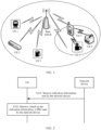
- FIG. 1 is a schematic diagram of a system architecture according to this application.
- the system includes a network device, which may be a base station (BS), and a plurality of terminal devices such as UE 1 to UE 6 shown in FIG. 1 that communicate with the base station.
- the base station may be a multi-beam base station, or may be a single-beam base station.
- the terminal device may be a fixed terminal device, or may be a mobile terminal device.
- the base station and the UE 1 to the UE 6 form a communication system.
- the base station may send indication information to one or more of the UE 1 to the UE 6, so that the one or more of the UE 1 to the UE 6 receive a SIB 1 based on the indication information.
- FIG. 2 is a flowchart of Embodiment 1 of a method for transmitting a system information block according to this application. As shown in FIG. 2 , in the foregoing system architecture, the method for transmitting a system information block specifically includes the following steps.
- the UE receives the indication information transmitted by the SIB 1 sent by the network device side.
- the indication information may be used to reconfigure the transmission period or the transmission location (that is, a time domain transmission location) of aperiodic transmission of the SIB1. That is, the network device sends an updated transmission period or updated transmission location of aperiodic transmission of the SIB 1 to the UE based on the indication information, so that the UE learns of an updated transmission status of the SIB 1.
- the indication information may indicate the transmission period of the SIB 1, and the transmission period may be any one of [5, 10, 20, 40, 80, 160] ms.
- the network device may deliver the indication information to the UE via DCI of the SIB1.
- the network device may indicate the transmission mode of the SIB1 by using 3 bits in a DCI field. For example, 000 indicates that the transmission period of the SIB1 is 5 ms, 001 indicates that the transmission period of the SIB1 is 10 ms, 010 indicates that the transmission period of the SIB1 is 20 ms, 011 indicates that the transmission period of the SIB1 is 40 ms, 100 indicates that the transmission period of the SIB1 is 60 ms, 101 indicates that the transmission period of the SIB1 is 80 ms, 110 indicates that the transmission period of the SIB1 is 160 ms, and 111 indicates that the transmission mode of the SIB1 is aperiodic transmission.
- a modulation mode of the SIB 1 is quadrature phase shift keying (QPSK).
- the network device may indicate the modulation mode of the SIB 1 by using a modulation and coding scheme (MCS) field in DCI.
- MCS modulation and coding scheme
- the network device may also indicate the transmission period or a quantity of repetitions of the SIB1 by using 1 bit of the MCS field in the DCI. For example, 1 indicates that the transmission period of the SIB 1 is less than 20 ms, and the quantity of repetitions of the SIB 1 is greater than 8. 0 indicates that the transmission period of the SIB 1 is greater than 20 ms, and the quantity of repetitions of the SIB 1 is less than 8.
- the UE When the UE receives a transmission period of a SIB 1 indicated by an SSB, the UE receives, based on the transmission period of the SIB 1 indicated by the SSB, the SIB1 in a beam direction corresponding to the SSB.
- the UE receives the transmission period of the SIB1 indicated by the DCI, and may determine that a transmission period of the SIB1 associated with an index of the SSB (for example, the SSB 1) is the transmission period of the SIB1 indicated by the DCI.
- the association means that there is a QCL relationship between the DCI and the SSB (or there is a QCL relationship between the PDCCH and the SSB).
- the period of the SIB 1 that has the QCL relationship only with this SSB is used as an indicated value that indicates the PDCCH of the SIB 1, but that a period of a SIB1 of another SSB is used as the indicated value is not assumed.
- the SIB1 of the another SSB represents a SIB1 that has a QCL relationship with the another SSB.
- the transmission periods of the SIB1 indicated in the DCI may be periods of PDCCHs and/or PDSCHs of a SIB1 associated with all SSBs transmitted in one period in which an SSB is transmitted. All the SSBs are SSBs in the beam directions, and the periods of the SIB1 associated with all the SSBs may be same periods.
- the network device may further indicate the transmission period of the SIB 1 using any one of the following fields in the PDCCH: a frequency domain resource assignment field for assignment of a PDSCH frequency domain resource, a time domain resource assignment field for assignment of a PDSCH time domain resource, a modulation and coding scheme field that indicates modulation and decoding, a VRB-to-PRB mapping field that indicates mapping from a virtual resource block to a physical resource block, a redundancy version field that indicates a redundancy version, and a system information indicator field that indicates a system information type.
- the network device may deliver the indication information to the UE using an SSB.
- the network device may indicate the transmission period of the SIB1 using a field of a non-cell-defining SSB or a field of a cell-defining SSB.
- the UE may determine, based on a value of an ssb-SubcarrierOffset field in a MIB, whether the SSB is a cell-defining SSB or a non-cell-defining SSB.
- a pdcch-ConfigSIB1 field in the cell-defining SSB indicates configuration information of the PDCCH of the SIB1
- a pdcch-ConfigSIB1 field in the non-cell-defining SSB does not indicate the configuration information of the PDCCH of the SIB1.
- the network device may indicate the transmission period of the SIB1 using the cell-defining SSB.
- the transmission period of the SIB1 is a transmission period corresponding to a beam direction, that is, the transmission period of the SIB1 associated with the SSB.
- the network device may send a series of SSBs such as an SSB1, an SSB2, and an SSB3 in different beam directions.
- the SSBs in the different beam directions may indicate same or different transmission periods of the SIB 1.
- a transmission period of the SIB1 indicated by the SSB1 is 10 ms
- a transmission period of the SIB1 indicated by the SSB2 is 20 ms
- a transmission period of the SIB1 indicated by the SSB3 is 10 ms.
- the UE receives a transmission period of a SIB1 indicated by an SSB
- the UE receives, based on the transmission period of the SIB 1 indicated by the SSB, the SIB1 in a beam direction corresponding to the SSB.
- An advantage of distinguishing the SSBs is that the SSBs in different beam directions indicate different transmission periods of the SIB1, so that overheads of blind detection performed by the UE can be reduced while network coverage is enhanced and transmission overheads on the network side are reduced.
- the SSB carries information on a PBCH, and the PBCH is used to carry the MIB.
- the MIB includes the following fields: a dmrs-TypeA-Position field for determining a position of a demodulation reference signal, a systemFrameNumber field for determining a frame number, a subCarrierSpacingCommon field for determining a data subcarrier spacing, a cellBarred field for determining whether a cell can be accessed, an intraFreqReselection field for performing intra-frequency cell reselection, an ssb-SubcarrierOffset field for determining an offset between an SSB subcarrier and a data subcarrier, and a pdcch-ConfigSIB1 field for determining configuration information of a PDCCH of a SIB1.
- the network device indicates the transmission period of the SIB1 using a field of a non-cell-defining SSB.
- a field of a non-cell-defining SSB For example, all or some fields of dmrs-TypeA-Position, intraFreqReselection, cellBarred, and subCarrierSpacingCommon indicate the transmission period of the SIB1.
- 1 bit of a dmrs-TypeA-Position field, 1 bit of an intraFreqReselection field, and 1 bit of a cellBarred field jointly indicate the transmission period of the SIB1, as described in the foregoing embodiment.
- the indication information may also indicate the transmission location of aperiodic transmission of the SIB 1.
- the network device delivers, to the UE using the DCI, the indication information that indicates the transmission location of the SIB 1.
- the DCI may indicate the transmission location of the SIB 1 in the following several implementations.
- the network device may separately indicate the four groups of transmission frames, and a same quantity of data bits is used for each group. For example, four bits are used for each group for indication, and therefore 4*4 bits are required to indicate the four groups of transmission frames.
- the first four bits are [1,1,0,0], which indicate that a SIB1 is sent in first and second transmission frames in a first group
- the second four bits are [1,0,0,1], which indicate that a SIB1 is sent in first and fourth transmission frames in a second group
- manners of indicating a SIB 1 in a third group and a fourth group are similar
- the network device may further perform joint indication on the four groups of transmission frames.
- the first half of a field indicates whether a SIB 1 is sent in each group of transmission frames, and the last half of the field indicates a transmission status of a SIB1 in a group in which the SIB1 is sent.
- eight bits are used for joint indication.
- the first four bits indicate sending statuses of a SIB1 of four groups of transmission frames, that is, the SIB 1 is sent and not sent in specific groups.
- the last four bits indicate sending statuses of transmission frames in a group in which the SIB1 is sent, that is, the SIB1 is sent in specific transmission frames in the group. For example, as shown in FIG.
- the first four bits are [1,1,0,0], which indicate that a SIB1 is sent in transmission frames in first and second groups.
- the last four bits are [1,0,1,0], which indicate that a SIB 1 is sent in the first and third transmission frames in the first group, and a SIB1 is sent in the first and third transmission frames in the second group.
- the UE may determine, based on the received indication information, the period of the SIB 1 whose transmission mode is periodic transmission, or the transmission location of the SIB 1 whose transmission mode is aperiodic transmission; and receive, based on the transmission period or the transmission location of the SIB 1, the SIB1 sent by the network device. This reduces overheads of blind detection performed by the UE.
- the UE receives the indication information sent by the network device, where the indication information indicates that a transmission period of the SIB 1 in one or more beam directions is 40 ms (the transmission period of the SIB1 is 20 ms by default for the UE).
- the UE learns, based on the indication information, that the transmission period of the SIB 1 in the one or more beam directions changes, and the UE receives the SIB 1 in the one or more beam directions based on a new transmission period. This process can reduce overheads of blind detection on the SIB 1 by the UE in a beam direction.
- the UE receives the indication information sent by the network device, where the indication information indicates that the transmission period of the SIB1 in one or more beam directions is 10 ms (the transmission period of the SIB1 is 20 ms by default for the UE).
- the UE learns, based on the indication information, that the transmission period of the SIB 1 in the one or more beam directions changes, and the UE receives the SIB 1 in the one or more beam directions based on a new transmission period. This process can improve reception performance of the UE.
- the UE receives the indication information sent by the network device, where the indication information indicates a transmission location of aperiodic transmission of the SIB 1 in one or more beam directions.
- the UE learns, based on the indication information, that the transmission location of the SIB 1 in the one or more beam directions changes, and the UE receives the SIB 1 sent in the one or more beam directions based on a new transmission location. This process can reduce overheads of blind detection on the SIB 1 by the UE in a beam direction, and improve reception performance of the UE.
- the UE determines, based on the indication information sent by the network device, the period of periodic transmission of the system information block, and receives, based on the period, the SIB1 sent by the network device; or the UE determines, based on the indication information sent by the network device, the transmission location of aperiodic transmission of the system information block, and receives, at the transmission location, the SIB1 sent by the network device.
- the network device sends the SIB1 based on the period or the transmission location. This can reduce transmission overheads on the network side.
- indication information is located in different information blocks, which can improve the processing efficiency of UE while enhancing network coverage.
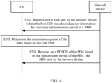
- FIG. 4 is a flowchart of Embodiment 2 of a method for transmitting a system information block according to this application. As shown in FIG. 4 , the method for transmitting a system information block specifically includes the following steps.
- the first SSB may alternatively be a cell-defining SSB, and the network device may indicate the transmission period of the SIB 1 using a pdcch-ConfigSIB 1 field in the first SSB.
- the first SSBs may alternatively be SSBs in a plurality of beam directions.
- the UE receives, in a corresponding beam direction based on a transmission period of the SIB1 indicated by the SSBs in different beam directions, the SIB1 sent by the network device.
- the SSBs in the different beam directions may indicate same or different transmission periods of the SIB1.
- the network device indicates the transmission period of the SIB 1 by using the first SSB, and the UE directly receives a PDCCH and the PDSCH based on the transmission period of the SIB1 indicated in the first SSB. This improves reception performance of the terminal device for the SIB1.
- FIG. 5 is a flowchart of Embodiment 3 of a method for transmitting a system information block according to this application. As shown in FIG. 5 , the method for transmitting a system information block specifically includes the following steps.
- the second SSB indicates configuration information of a PDCCH of the SIB1.
- S302. Determine, based on the second SSB, configuration information of a PDCCH of a SIB1 associated with the second SSB.
- S303 Receive, on the PDCCH of the SIB1 based on the configuration information, DCI sent by the network device, where the DCI includes indication information that indicates a transmission period of the SIB 1.
- S305 Receive, on a PDSCH of the SIB1 based on the transmission period of the SIB 1, the SIB1 sent by the network device.
- the second SSB is a cell-defining SSB, and includes a pdcch-ConfigSIB1 field, which indicates the configuration information of the PDCCH of the SIB1.
- the second SSB may be an SSB in a beam direction.
- UE receives the second SSB sent by the network device in the beam direction, and determines, based on the second SSB, the PDCCH of the SIB1 associated with the second SSB.
- the network device delivers, to the UE by using the DCI of the SIB 1, the indication information that indicates the transmission period of the SIB 1.
- the UE receives the DCI on the PDCCH of the SIB 1 associated with the second SSB, and determines the transmission period of the SIB1 based on a field in the DCI, so that the UE receives, on the PDSCH of the SIB1 based on the transmission period of the SIB 1, the SIB1 sent by the network device.
- the second SSBs may alternatively be SSBs in a plurality of beam directions.
- the UE receives the second SSBs sent by the network device in the plurality of beam directions, determines the PDCCH of the SIB1 associated with the second SSB in each beam direction, separately receives DCI of the SIB1 on the PDCCHs in different beam directions, and receives, based on the transmission period of the SIB 1 indicated in each piece of DCI, the SIB 1 sent by the network device in the different beam directions.
- the network device indicates the transmission period of the SIB1 by using the PDCCH of the SIB 1 (the DCI of the SIB 1), and the UE receives the PDCCH and the PDSCH based on the transmission period of the SIB1 indicated in the PDCCH of the SIB 1, to improve reception performance of the terminal device for the SIB1.
- the methods and the operations implemented by the terminal device may alternatively be implemented by a component (for example, a chip or a circuit) that can be used in the terminal device
- the methods and the operations implemented by the network device may alternatively be implemented by a component (for example, a chip or a circuit) that can be used in the network device.
- each network element such as the terminal device or the network device, includes a corresponding hardware structure and/or software module for performing each function.
- each network element such as the terminal device or the network device, includes a corresponding hardware structure and/or software module for performing each function.
- a person skilled in the art may be aware that, in combination with units and algorithm steps of the examples described in embodiments disclosed in this specification, this application may be implemented by hardware or a combination of hardware and computer software. Whether a function is performed by hardware or hardware driven by computer software depends on particular applications and design constraints of the technical solutions. A person skilled in the art may use different methods to implement the described functions for each particular application, but it should not be considered that the implementation goes beyond the scope of this application.
- function modules of the terminal device or the network device may be divided based on the foregoing method examples.
- function modules may be divided corresponding to functions, or two or more functions may be integrated into one processing module.
- the integrated module may be implemented in a form of hardware, or may be implemented in a form of a software functional module. It should be noted that, in embodiments of this application, division into the modules is an example and is merely logical function division, and may be other division in an actual implementation. An example in which various functional modules are divided according to corresponding functions is used below for description.
- FIG. 6 is a schematic diagram of a structure of a communication apparatus according to this application.
- the communication apparatus 400 provided in this embodiment includes:
- the transceiver module 401 is specifically configured to: receive a first SSB sent by the network device, where the first SSB includes the indication information; or receive downlink control information DCI that is of the SIB1 and that is sent by the network device, where the DCI includes the indication information.
- the transceiver module 401 is specifically configured to:
- the indication information in the DCI indicates a transmission period of the SIB 1 associated with an index of the second SSB.
- a processing module 402 is specifically configured to:
- the communication apparatus provided in this embodiment is configured to perform the technical solutions on the terminal device side in the foregoing method embodiments.
- An implementation principle and technical effects of the communication apparatus are similar to those of the method embodiments, and details are not described herein again.
- FIG. 7 is a schematic diagram of a structure of a communication apparatus according to this application.
- the communication apparatus 500 provided in this embodiment includes:
- the transceiver module 502 is specifically configured to:
- the transceiver module 502 is specifically configured to:
- the indication information in the DCI indicates a transmission period of the SIB 1 associated with an index of the second SSB.
- the communication apparatus provided in this embodiment is configured to perform the technical solutions on the network device side in the foregoing method embodiments.
- An implementation principle and technical effects of the communication apparatus are similar to those of the method embodiments, and details are not described herein again.
- FIG. 8 is a simplified schematic diagram of a structure of hardware of the terminal device.
- the terminal device includes a processor, a memory, a radio frequency circuit, an antenna, and an input/output apparatus.
- the processor is mainly configured to process a communication protocol and communication data, control the terminal device, execute a software program, process data of the software program, and the like.
- the memory is configured to store the software program and the data.
- the radio frequency circuit is mainly configured to perform conversion between a baseband signal and a radio frequency signal and process the radio frequency signal.
- the antenna is mainly configured to send and receive a radio frequency signal in a form of an electromagnetic wave.
- the input/output apparatus for example, a touchscreen, a display, or a keyboard, is mainly configured to receive data input by a user, and output data to the user. It should be noted that some types of terminal devices may have no input/output apparatus.
- the processor When data needs to be sent, the processor performs baseband processing on the to-be-sent data, and then outputs a baseband signal to the radio frequency circuit. After performing radio frequency processing on the baseband signal, the radio frequency circuit sends a radio frequency signal in a form of an electromagnetic wave to the outside through the antenna.
- the radio frequency circuit receives a radio frequency signal through the antenna, converts the radio frequency signal into a baseband signal, and outputs the baseband signal to the processor.
- the processor converts the baseband signal into data and processes the data.
- FIG. 8 shows only one memory and one processor.
- An actual terminal device product may include one or more processors and one or more memories.
- the memory may also be referred to as a storage medium, a storage device, or the like.
- the memory may be deployed independent of the processor or may be integrated with the processor. This is not limited in this embodiment of this application.
- the antenna and the radio frequency circuit that have transceiver functions may be considered as a transceiver unit of the terminal device, and the processor that has a processing function may be considered as a processing unit of the terminal device.
- the terminal device includes a transceiver unit 810 and a processing unit 820.
- the transceiver unit may also be referred to as a transceiver, a transceiver machine, a transceiver apparatus, or the like.
- the processing unit may also be referred to as a processor, a processing board, a processing module, a processing apparatus, or the like.
- a component that is in the transceiver unit 810 and that is configured to implement a receiving function may be considered as a receiving unit
- a component that is in the transceiver unit 810 and that is configured to implement a sending function may be considered as a sending unit.
- the transceiver unit 810 includes the receiving unit and the sending unit.
- the transceiver unit may sometimes be referred to as a transceiver, a transceiver machine, a transceiver circuit, or the like.
- the receiving unit may also be sometimes referred to as a receiver, a receiver machine, a receiver circuit, or the like.
- the sending unit sometimes may also be referred to as a transmitter, a transmitter machine, a transmitter circuit, or the like.
- transceiver unit 810 is configured to perform a sending operation and a receiving operation on the terminal device side in the foregoing method embodiments
- processing unit 820 is configured to perform an operation other than the receiving and sending operations of the terminal device in the foregoing method embodiments.
- FIG. 10 is a simplified schematic diagram of a structure of hardware of the network device.
- the communication apparatus 1000 includes one or more radio frequency units, for example, a remote radio unit (RRU) 1010 and one or more baseband units (BBU) (which may also be referred to as a digital unit (DU)) 1020.
- the RRU 1010 may be referred to as a transceiver module, and corresponds to the transceiver module 502 in FIG. 7 .
- the transceiver module may also be referred to as a transceiver machine, a transceiver circuit, a transceiver, or the like, and may include at least one antenna 1011 and a radio frequency unit 1012.
- the RRU 1010 is mainly configured to send and receive a radio frequency signal, and perform conversion between the radio frequency signal and a baseband signal.
- the RRU 1010 is configured to send indication information to a terminal device.
- the BBU 1020 is mainly configured to perform baseband processing, control the base station, and the like.
- the RRU 1010 and the BBU 1020 may be physically disposed together, or may be physically disposed separately, namely, a distributed base station.
- the BBU 1020 is a control center of the base station, may also be referred to as a processing module, and is mainly configured to implement a baseband processing function such as channel coding, multiplexing, modulation, and frequency spread.
- the BBU (the processing module) may be configured to control the base station to perform an operation procedure related to the network device in the foregoing method embodiment, for example, generate the foregoing indication information.
- the BBU 1020 may include one or more boards.
- a plurality of boards may jointly support a radio access network (for example, an LTE network) having a single access standard, or may separately support radio access networks (for example, the LTE network, a 5G network, or another network) having different access standards.
- the BBU 1020 further includes a memory 1021 and a processor 1022.
- the memory 1021 is configured to store necessary instructions and data.
- the processor 1022 is configured to control the base station to perform a necessary action, for example, control the base station to perform the operation procedure related to the network device in the foregoing method embodiments.
- the memory 1021 and the processor 1022 may serve one or more boards. In other words, a memory and a processor may be separately deployed on each board. Alternatively, the plurality of boards may share a same memory and processor. In addition, a necessary circuit may further be deployed on each board.
- this application further provides a computer storage medium, configured to store a computer program.
- the computer program When the computer program is run on a computer, the computer is enabled to perform the method in any one of the embodiments shown in FIG. 2 , FIG. 4 , and FIG. 5 .
- this application further provides a computer program product.
- the computer program product runs on a computer, the computer is enabled to perform the method in any one of the embodiments shown in FIG. 2 , FIG. 4 , and FIG. 5 .
- this application further provides a chip, including a processor and an interface, and configured to invoke, from a memory, a computer program stored in the memory, and run the computer program, to perform the method in any one of the embodiments shown in FIG. 2 , FIG. 4 , and FIG. 5 .
- this application further provides a system.
- the system includes the foregoing one or more terminal devices and the foregoing one or more network devices.
- the memory mentioned in embodiments of this application may be a volatile memory or a non-volatile memory, or may include both a volatile memory and a non-volatile memory.
- the non-volatile memory may be a read-only memory (ROM), a programmable read-only memory (PROM), an erasable programmable read-only memory (EPROM), an electrically erasable programmable read-only memory (EEPROM), or a flash memory.
- the volatile memory may be a random access memory (RAM), and is used as an external cache.
- the processor is a general-purpose processor, a DSP, an ASIC, an FPGA, or another programmable logic device, discrete gate or transistor logic device, or discrete hardware component
- the memory a storage module
Landscapes
- Engineering & Computer Science (AREA)
- Computer Security & Cryptography (AREA)
- Computer Networks & Wireless Communication (AREA)
- Signal Processing (AREA)
- Mobile Radio Communication Systems (AREA)
Claims (11)
- Verfahren zum Übertragen eines Systeminformationsblocks in ein neues Funk-, NR, Netzwerk, umfassend:a) Empfangen (S101) von Angabeinformationen, die seitens einer Basisstation gesendet wurden, durch eine Benutzereinrichtung, UE, wobei die Angabeinformationen eine Übertragungsperiode der periodischen Übertragung eines Systeminformationsblocks 1, SIB1, angeben, oder einen Übertragungsort von aperiodischer Übertragung des SIB1 angeben; undb) Empfangen (S102) des SIB 1, der seitens der Basisstation gesendet wurde, durch die UE basierend auf den Angabeinformationen;wobei das Empfangen der Angabeinformationen, die seitens der Basisstation gesendet wurden, umfasst:• Empfangen (S201) eines ersten Synchronisationssignalblocks, SSB, der seitens der Basisstation gesendet wurde, durch die UE, wobei der erste SSB Informationen zu einem physischen Broadcast-Kanal, PBCH, trägt und der PBCH verwendet wird, um einen Masterinformationsblock, MIB, zu tragen, der die folgenden Felder einschließt: ein "dmrs-TypeA"-Positionsfeld zum Bestimmen einer Position eines Demodulationsreferenzsignals, ein "systemFrameNumber"-Feld zum Bestimmen einer Frame-Nummer, ein "subCarrierSpacingCommon"-Feld zum Bestimmen eines Datensubträgerabstands, ein "cellBarred"-Feld zum Bestimmen, ob auf eine Zelle zugegriffen werden kann, ein "intraFreqReselection"-Feld zum Durchführen von erneuter Intrafrequenzzellauswahl, ein "ssb-SubcarrierOffset"-Feld zum Bestimmen eines Versatzes zwischen einem SSB-Subträger und einem Datensubträger, und ein "pdcch-ConfigSIB1"-Feld zum Bestimmen von Konfigurationsinformationen eines PDCCH eines SIB1; und wobei alle oder einige Felder von "dmrs-TypeA"-Position, "intraFreqReselection", "cellBarred" und "subCarrierSpacingCommon" die Übertragungsperiode des SIB1 angeben; oder• Empfangen (S303) von "Downlink"-Steuerinformationen, DCI, die von dem SIB 1 sind und seitens der Basisstation gesendet wurden, durch die UE, wobei Übertragungs-Frames, die 10 ms entsprechen, zu mehreren Gruppen kombiniert werden, und Datenbits in den DCI einen Übertragungsstatus des SIB1 in den Gruppen der Übertragungs-Frames angeben.
- Verfahren nach Anspruch 1, wobei das Empfangen der seitens der Basisstation gesendeten DCI umfassen:Empfangen (S301) eines zweiten SSB, der seitens der Basisstation gesendet wurde, wobei der zweite SSB Konfigurationsinformationen eines physischen "Downlink"-Steuerkanals, PDCCH, des SIB1 angibt; undEmpfangen (S303) der DCI des seitens der Basisstation gesendeten SIB1 auf dem PDCCH basierend auf den Konfigurationsinformationen.
- Verfahren nach Anspruch 2, wobei eine quasi "Colocation"-, QCL-, Beziehung zwischen dem zweiten SSB und dem PDCCH vorhanden ist.
- Verfahren nach einem der Ansprüche 1 bis 3, wobei das Empfangen des seitens der Basisstation gesendeten SIB1 basierend auf den Angabeinformationen umfasst:Bestimmen (S202, S304) der Übertragungsperiode des SIB1 oder des Übertragungsorts des SIB 1 basierend auf den Angabeinformationen; undEmpfangen (S203, S305) des SIB1 basierend auf der Übertragungsperiode oder dem Übertragungsort des SIB1 auf einem physischen gemeinsamen "Downlink"-Kanal, PDSCH, wobei der SIB1 seitens der Basisstation gesendet wurde.
- Verfahren zum Übertragen eines Systeminformationsblocks in ein neues Funk-, NR, Netzwerk, umfassend:a) Generieren von Angabeinformationen seitens einer Basisstation, wobei die Angabeinformationen eine Übertragungsperiode von periodischer Übertragung eines Systeminformationsblocks 1, SIB1, angeben oder einen Übertragungsort von aperiodischer Übertragung des SIB1 angeben; undb) Senden der Angabeinformationen seitens der Basisstation an eine Benutzereinrichtung, UE;wobei das Senden der Angabeinformationen an die UE umfasst:• Senden eines ersten Synchronisationssignalblocks, SSB, wobei der erste SSB Informationen auf einem physischen Broadcast-Kanal, PBCH, trägt und der PBCH verwendet wird, um einen Masterinformationsblock, MIB, zu tragen, der die folgenden Felder einschließt: ein "dmrs-TypeA"-Positionsfeld zum Bestimmen einer Position eines Demodulationsreferenzsignals, ein "systemFrameNumber"-Feld zum Bestimmen einer Frame-Nummer, ein "subCarrierSpacingCommon"-Feld zum Bestimmen eines Datensubträgerabstands, ein "cellBarred"-Feld zum Bestimmen, ob auf eine Zelle zugegriffen werden kann, ein "intraFreqReselection"-Feld zum Durchführen von erneuter Intrafrequenzzellauswahl, ein "ssb-SubcarrierOffset"-Feld zum Bestimmen eines Versatzes zwischen einem SSB-Subträger und einem Datensubträger, und ein "pdcch-ConfigSIB 1"-Feld zum Bestimmen von Konfigurationsinformationen eines PDCCH eines SIB1;
und wobei alle oder einige Felder von "dmrs-TypeA"-Position, "intraFreqReselection", "cellBarred" und "subCarrierSpacingCommon" die Übertragungsperiode des SIB1 angeben; oder• Senden von "Downlink"-Steuerinformationen, DCI, die von dem SIB1 sind, wobei Übertragungs-Frames, die 10 ms entsprechen, zu mehreren Gruppen kombiniert werden, und Datenbits in den DCI einen Übertragungsstatus des SIB1 in den Gruppen der Übertragungs-Frames angeben. - Verfahren nach Anspruch 5, wobei das Senden der DCI an die UE umfasst:Senden eines zweiten SSB an die UE, wobei der zweite SSB Konfigurationsinformationen eines physischen "Downlink"-Steuerkanals, PDCCH, des SIB1 angibt; undSenden der DCI des SIB 1 an die UE auf dem PDCCH basierend auf den Konfigurationsinformationen.
- Verfahren nach Anspruch 6, wobei eine quasi "Colocation"-, QCL-, Beziehung zwischen dem zweiten SSB und dem PDCCH vorhanden ist.
- Kommunikationsgerät (400), wobei das Kommunikationsgerät eine Benutzereinrichtung, UE, ist und konfiguriert ist, das Verfahren gemäß einem der Ansprüche 1 bis 4 durchzuführen.
- Kommunikationsgerät (500), wobei das Kommunikationsgerät eine Basisstation ist und konfiguriert ist, das Verfahren gemäß einem der Ansprüche 5 bis 7 durchzuführen.
- Computerspeichermedium, das konfiguriert ist, ein Computerprogramm zu speichern, wobeider Computer in die Lage versetzt wird, das Verfahren gemäß einem der Ansprüche 1 bis 4 durchzuführen, wenn das Computerprogramm auf einem Computer einer Benutzereinrichtung ausgeführt wird, undder Computer in die Lage versetzt wird, das Verfahren gemäß einem der Ansprüche 5 bis 7 durchzuführen, wenn das Computerprogramm auf einem Computer einer Basisstation ausgeführt wird.
- Computerprogrammprodukt, wobeider Computer in die Lage versetzt wird, das Verfahren gemäß einem der Ansprüche 1 bis 4 durchzuführen, wenn das Computerprogrammprodukt auf einem Computer einer Benutzereinrichtung läuft, undder Computer in die Lage versetzt wird, das Verfahren gemäß einem der Ansprüche 5 bis 7 durchzuführen, wenn das Computerprogramm auf einem Computer einer Basisstation ausgeführt wird.
Applications Claiming Priority (1)
| Application Number | Priority Date | Filing Date | Title |
|---|---|---|---|
| PCT/CN2020/072499 WO2021142718A1 (zh) | 2020-01-16 | 2020-01-16 | 传输系统信息块的方法、装置和存储介质 |
Publications (3)
| Publication Number | Publication Date |
|---|---|
| EP4072202A1 EP4072202A1 (de) | 2022-10-12 |
| EP4072202A4 EP4072202A4 (de) | 2022-12-21 |
| EP4072202B1 true EP4072202B1 (de) | 2023-12-27 |
Family
ID=76863332
Family Applications (1)
| Application Number | Title | Priority Date | Filing Date |
|---|---|---|---|
| EP20914400.5A Active EP4072202B1 (de) | 2020-01-16 | 2020-01-16 | Verfahren und vorrichtung zum übertragen von systeminformationsblöcken, und speichermedium |
Country Status (4)
| Country | Link |
|---|---|
| US (1) | US12520231B2 (de) |
| EP (1) | EP4072202B1 (de) |
| CN (1) | CN114902743A (de) |
| WO (1) | WO2021142718A1 (de) |
Families Citing this family (9)
| Publication number | Priority date | Publication date | Assignee | Title |
|---|---|---|---|---|
| US12150134B2 (en) * | 2021-01-08 | 2024-11-19 | Qualcomm Incorporated | Master information block and download control information design for higher bands |
| CN117040702A (zh) * | 2022-04-29 | 2023-11-10 | 华为技术有限公司 | 通信方法与装置 |
| CN117879771A (zh) * | 2022-09-30 | 2024-04-12 | 中国移动通信有限公司研究院 | 一种传输指示方法、装置、通信设备和存储介质 |
| US12621781B2 (en) * | 2022-12-09 | 2026-05-05 | Nokia Technologies Oy | Sensing in cellular communication networks |
| WO2025091389A1 (zh) * | 2023-11-02 | 2025-05-08 | 深圳传音控股股份有限公司 | 传输方法、通信设备及存储介质 |
| CN120380814A (zh) * | 2023-12-28 | 2025-07-25 | 北京小米移动软件有限公司 | 信息指示方法、终端、网络设备、通信系统和存储介质 |
| CN120499786A (zh) * | 2024-02-08 | 2025-08-15 | 荣耀终端股份有限公司 | 一种通信方法、设备和系统 |
| WO2025209179A1 (zh) * | 2024-04-03 | 2025-10-09 | 华为技术有限公司 | 系统消息块发送方法和装置 |
| WO2026000389A1 (en) * | 2024-06-28 | 2026-01-02 | Nec Corporation | Devices and methods for communication |
Family Cites Families (10)
| Publication number | Priority date | Publication date | Assignee | Title |
|---|---|---|---|---|
| CN101217689B (zh) * | 2007-01-05 | 2011-08-17 | 电信科学技术研究院 | 一种系统消息传送方法及其实现装置 |
| CN102651890B (zh) * | 2011-02-24 | 2015-03-25 | 电信科学技术研究院 | 一种系统信息的传输方法及装置 |
| CN104285483B (zh) * | 2013-04-07 | 2018-07-13 | 华为技术有限公司 | 传输公共信号的方法及其装置 |
| CN108848546B (zh) * | 2013-12-24 | 2021-01-29 | 华为技术有限公司 | 小区系统消息的接收方法、用户设备及通信系统 |
| WO2019022577A1 (ko) * | 2017-07-28 | 2019-01-31 | 엘지전자 주식회사 | 방송 채널을 송수신하는 방법 및 이를 위한 장치 |
| JP7247232B2 (ja) * | 2018-06-21 | 2023-03-28 | 鴻穎創新有限公司 | 無線通信システムにおいてセル(再)選択を遂行するための方法及び装置 |
| KR20210042116A (ko) * | 2018-08-10 | 2021-04-16 | 가부시키가이샤 엔티티 도코모 | 유저단말 및 무선 통신 방법 |
| KR102810017B1 (ko) * | 2019-07-08 | 2025-05-20 | 삼성전자 주식회사 | 무선 통신 시스템에서 데이터 채널의 송수신 방법 및 장치 |
| US12114307B2 (en) * | 2019-07-09 | 2024-10-08 | Beijing Xiaomi Mobile Software Co., Ltd. | Method and apparatus for information processing |
| CN113574821A (zh) * | 2019-11-12 | 2021-10-29 | Oppo广东移动通信有限公司 | 无线通信的方法、网络设备和终端设备 |
-
2020
- 2020-01-16 EP EP20914400.5A patent/EP4072202B1/de active Active
- 2020-01-16 WO PCT/CN2020/072499 patent/WO2021142718A1/zh not_active Ceased
- 2020-01-16 CN CN202080091765.4A patent/CN114902743A/zh active Pending
-
2022
- 2022-07-15 US US17/865,789 patent/US12520231B2/en active Active
Also Published As
| Publication number | Publication date |
|---|---|
| EP4072202A1 (de) | 2022-10-12 |
| CN114902743A (zh) | 2022-08-12 |
| EP4072202A4 (de) | 2022-12-21 |
| WO2021142718A1 (zh) | 2021-07-22 |
| US20220353793A1 (en) | 2022-11-03 |
| US12520231B2 (en) | 2026-01-06 |
Similar Documents
| Publication | Publication Date | Title |
|---|---|---|
| US12520231B2 (en) | Method for transmitting system information block, apparatus, and storage medium | |
| US10797777B2 (en) | Method for communication between terminals, network-side device, and terminal | |
| US11178629B2 (en) | Information sending and receiving method, network device, and terminal device | |
| WO2018192015A1 (zh) | 时频资源传输方向的配置方法和装置 | |
| CN108347778A (zh) | 通信方法及装置 | |
| CN111901875A (zh) | 指示方法、上行传输方法、装置、服务节点、终端及介质 | |
| WO2020051774A1 (zh) | 通信方法、终端设备和网络设备 | |
| US12225585B2 (en) | Wireless communication method and terminal device | |
| EP4629542A1 (de) | Informationsübertragungsverfahren und -vorrichtung sowie netzwerkseitige vorrichtung und endgerät | |
| CN115244877A (zh) | 监听时机的确定方法及装置 | |
| US20240430069A1 (en) | Bandwidth part processing method, terminal device and network device | |
| KR102782743B1 (ko) | Nr v2x 시스템에서 사이드링크 피드백 절차 수행 방법 및 그 장치 | |
| US20210211328A1 (en) | Wireless communication method, transmitting node and receiving node | |
| WO2023124718A1 (zh) | 一种通信方法和装置 | |
| CN108811074A (zh) | 信息传输方法及装置 | |
| JP2022532351A (ja) | D2dシステムにおける通信方法及び端末装置、ネットワーク装置 | |
| CN116391424A (zh) | 一种随机接入方法、通信设备及存储介质 | |
| CN111435892B (zh) | 接收数据的方法和装置 | |
| WO2021216734A1 (en) | Methods and apparatus for orthogonal sequence transmission with frequency hopping | |
| JP2021517427A (ja) | リソーススケジューリング方法、データ送信方法及びその装置、通信システム | |
| CN113365356B (zh) | 无线通信方法、网络设备和终端设备 | |
| US20210258901A1 (en) | Method and device for transmitting downlink control information | |
| US20250393075A1 (en) | Preamble sequence sending and receiving methods, apparatuses and storage medium | |
| EP3595224B1 (de) | Informationsübertragungsverfahren, endgerätevorrichtung und netzwerkvorrichtung | |
| EP4164163B1 (de) | Informationsübertragungsverfahren und -vorrichtung, endgerätevorrichtung und netzwerkvorrichtung |
Legal Events
| Date | Code | Title | Description |
|---|---|---|---|
| STAA | Information on the status of an ep patent application or granted ep patent |
Free format text: STATUS: THE INTERNATIONAL PUBLICATION HAS BEEN MADE |
|
| PUAI | Public reference made under article 153(3) epc to a published international application that has entered the european phase |
Free format text: ORIGINAL CODE: 0009012 |
|
| STAA | Information on the status of an ep patent application or granted ep patent |
Free format text: STATUS: REQUEST FOR EXAMINATION WAS MADE |
|
| 17P | Request for examination filed |
Effective date: 20220707 |
|
| AK | Designated contracting states |
Kind code of ref document: A1 Designated state(s): AL AT BE BG CH CY CZ DE DK EE ES FI FR GB GR HR HU IE IS IT LI LT LU LV MC MK MT NL NO PL PT RO RS SE SI SK SM TR |
|
| A4 | Supplementary search report drawn up and despatched |
Effective date: 20221123 |
|
| RIC1 | Information provided on ipc code assigned before grant |
Ipc: H04W 48/12 20090101ALI20221117BHEP Ipc: H04W 48/16 20090101AFI20221117BHEP |
|
| DAV | Request for validation of the european patent (deleted) | ||
| DAX | Request for extension of the european patent (deleted) | ||
| GRAP | Despatch of communication of intention to grant a patent |
Free format text: ORIGINAL CODE: EPIDOSNIGR1 |
|
| STAA | Information on the status of an ep patent application or granted ep patent |
Free format text: STATUS: GRANT OF PATENT IS INTENDED |
|
| RIC1 | Information provided on ipc code assigned before grant |
Ipc: H04W 48/12 20090101ALI20230630BHEP Ipc: H04W 48/16 20090101AFI20230630BHEP |
|
| INTG | Intention to grant announced |
Effective date: 20230718 |
|
| GRAS | Grant fee paid |
Free format text: ORIGINAL CODE: EPIDOSNIGR3 |
|
| GRAA | (expected) grant |
Free format text: ORIGINAL CODE: 0009210 |
|
| STAA | Information on the status of an ep patent application or granted ep patent |
Free format text: STATUS: THE PATENT HAS BEEN GRANTED |
|
| AK | Designated contracting states |
Kind code of ref document: B1 Designated state(s): AL AT BE BG CH CY CZ DE DK EE ES FI FR GB GR HR HU IE IS IT LI LT LU LV MC MK MT NL NO PL PT RO RS SE SI SK SM TR |
|
| REG | Reference to a national code |
Ref country code: GB Ref legal event code: FG4D |
|
| REG | Reference to a national code |
Ref country code: CH Ref legal event code: EP |
|
| REG | Reference to a national code |
Ref country code: DE Ref legal event code: R096 Ref document number: 602020023620 Country of ref document: DE |
|
| REG | Reference to a national code |
Ref country code: IE Ref legal event code: FG4D |
|
| PG25 | Lapsed in a contracting state [announced via postgrant information from national office to epo] |
Ref country code: GR Free format text: LAPSE BECAUSE OF FAILURE TO SUBMIT A TRANSLATION OF THE DESCRIPTION OR TO PAY THE FEE WITHIN THE PRESCRIBED TIME-LIMIT Effective date: 20240328 |
|
| REG | Reference to a national code |
Ref country code: LT Ref legal event code: MG9D |
|
| PG25 | Lapsed in a contracting state [announced via postgrant information from national office to epo] |
Ref country code: LT Free format text: LAPSE BECAUSE OF FAILURE TO SUBMIT A TRANSLATION OF THE DESCRIPTION OR TO PAY THE FEE WITHIN THE PRESCRIBED TIME-LIMIT Effective date: 20231227 |
|
| PG25 | Lapsed in a contracting state [announced via postgrant information from national office to epo] |
Ref country code: ES Free format text: LAPSE BECAUSE OF FAILURE TO SUBMIT A TRANSLATION OF THE DESCRIPTION OR TO PAY THE FEE WITHIN THE PRESCRIBED TIME-LIMIT Effective date: 20231227 |
|
| PG25 | Lapsed in a contracting state [announced via postgrant information from national office to epo] |
Ref country code: LT Free format text: LAPSE BECAUSE OF FAILURE TO SUBMIT A TRANSLATION OF THE DESCRIPTION OR TO PAY THE FEE WITHIN THE PRESCRIBED TIME-LIMIT Effective date: 20231227 Ref country code: GR Free format text: LAPSE BECAUSE OF FAILURE TO SUBMIT A TRANSLATION OF THE DESCRIPTION OR TO PAY THE FEE WITHIN THE PRESCRIBED TIME-LIMIT Effective date: 20240328 Ref country code: FI Free format text: LAPSE BECAUSE OF FAILURE TO SUBMIT A TRANSLATION OF THE DESCRIPTION OR TO PAY THE FEE WITHIN THE PRESCRIBED TIME-LIMIT Effective date: 20231227 Ref country code: ES Free format text: LAPSE BECAUSE OF FAILURE TO SUBMIT A TRANSLATION OF THE DESCRIPTION OR TO PAY THE FEE WITHIN THE PRESCRIBED TIME-LIMIT Effective date: 20231227 Ref country code: BG Free format text: LAPSE BECAUSE OF FAILURE TO SUBMIT A TRANSLATION OF THE DESCRIPTION OR TO PAY THE FEE WITHIN THE PRESCRIBED TIME-LIMIT Effective date: 20240327 |
|
| REG | Reference to a national code |
Ref country code: NL Ref legal event code: MP Effective date: 20231227 |
|
| REG | Reference to a national code |
Ref country code: AT Ref legal event code: MK05 Ref document number: 1645705 Country of ref document: AT Kind code of ref document: T Effective date: 20231227 |
|
| PG25 | Lapsed in a contracting state [announced via postgrant information from national office to epo] |
Ref country code: NL Free format text: LAPSE BECAUSE OF FAILURE TO SUBMIT A TRANSLATION OF THE DESCRIPTION OR TO PAY THE FEE WITHIN THE PRESCRIBED TIME-LIMIT Effective date: 20231227 |
|
| PG25 | Lapsed in a contracting state [announced via postgrant information from national office to epo] |
Ref country code: SE Free format text: LAPSE BECAUSE OF FAILURE TO SUBMIT A TRANSLATION OF THE DESCRIPTION OR TO PAY THE FEE WITHIN THE PRESCRIBED TIME-LIMIT Effective date: 20231227 Ref country code: RS Free format text: LAPSE BECAUSE OF FAILURE TO SUBMIT A TRANSLATION OF THE DESCRIPTION OR TO PAY THE FEE WITHIN THE PRESCRIBED TIME-LIMIT Effective date: 20231227 Ref country code: NO Free format text: LAPSE BECAUSE OF FAILURE TO SUBMIT A TRANSLATION OF THE DESCRIPTION OR TO PAY THE FEE WITHIN THE PRESCRIBED TIME-LIMIT Effective date: 20240327 Ref country code: NL Free format text: LAPSE BECAUSE OF FAILURE TO SUBMIT A TRANSLATION OF THE DESCRIPTION OR TO PAY THE FEE WITHIN THE PRESCRIBED TIME-LIMIT Effective date: 20231227 Ref country code: LV Free format text: LAPSE BECAUSE OF FAILURE TO SUBMIT A TRANSLATION OF THE DESCRIPTION OR TO PAY THE FEE WITHIN THE PRESCRIBED TIME-LIMIT Effective date: 20231227 Ref country code: HR Free format text: LAPSE BECAUSE OF FAILURE TO SUBMIT A TRANSLATION OF THE DESCRIPTION OR TO PAY THE FEE WITHIN THE PRESCRIBED TIME-LIMIT Effective date: 20231227 |
|
| PG25 | Lapsed in a contracting state [announced via postgrant information from national office to epo] |
Ref country code: IS Free format text: LAPSE BECAUSE OF FAILURE TO SUBMIT A TRANSLATION OF THE DESCRIPTION OR TO PAY THE FEE WITHIN THE PRESCRIBED TIME-LIMIT Effective date: 20240427 |
|
| PG25 | Lapsed in a contracting state [announced via postgrant information from national office to epo] |
Ref country code: CZ Free format text: LAPSE BECAUSE OF FAILURE TO SUBMIT A TRANSLATION OF THE DESCRIPTION OR TO PAY THE FEE WITHIN THE PRESCRIBED TIME-LIMIT Effective date: 20231227 Ref country code: AT Free format text: LAPSE BECAUSE OF FAILURE TO SUBMIT A TRANSLATION OF THE DESCRIPTION OR TO PAY THE FEE WITHIN THE PRESCRIBED TIME-LIMIT Effective date: 20231227 |
|
| PG25 | Lapsed in a contracting state [announced via postgrant information from national office to epo] |
Ref country code: SK Free format text: LAPSE BECAUSE OF FAILURE TO SUBMIT A TRANSLATION OF THE DESCRIPTION OR TO PAY THE FEE WITHIN THE PRESCRIBED TIME-LIMIT Effective date: 20231227 |
|
| PG25 | Lapsed in a contracting state [announced via postgrant information from national office to epo] |
Ref country code: SM Free format text: LAPSE BECAUSE OF FAILURE TO SUBMIT A TRANSLATION OF THE DESCRIPTION OR TO PAY THE FEE WITHIN THE PRESCRIBED TIME-LIMIT Effective date: 20231227 Ref country code: SK Free format text: LAPSE BECAUSE OF FAILURE TO SUBMIT A TRANSLATION OF THE DESCRIPTION OR TO PAY THE FEE WITHIN THE PRESCRIBED TIME-LIMIT Effective date: 20231227 Ref country code: RO Free format text: LAPSE BECAUSE OF FAILURE TO SUBMIT A TRANSLATION OF THE DESCRIPTION OR TO PAY THE FEE WITHIN THE PRESCRIBED TIME-LIMIT Effective date: 20231227 Ref country code: IT Free format text: LAPSE BECAUSE OF FAILURE TO SUBMIT A TRANSLATION OF THE DESCRIPTION OR TO PAY THE FEE WITHIN THE PRESCRIBED TIME-LIMIT Effective date: 20231227 Ref country code: IS Free format text: LAPSE BECAUSE OF FAILURE TO SUBMIT A TRANSLATION OF THE DESCRIPTION OR TO PAY THE FEE WITHIN THE PRESCRIBED TIME-LIMIT Effective date: 20240427 Ref country code: EE Free format text: LAPSE BECAUSE OF FAILURE TO SUBMIT A TRANSLATION OF THE DESCRIPTION OR TO PAY THE FEE WITHIN THE PRESCRIBED TIME-LIMIT Effective date: 20231227 Ref country code: CZ Free format text: LAPSE BECAUSE OF FAILURE TO SUBMIT A TRANSLATION OF THE DESCRIPTION OR TO PAY THE FEE WITHIN THE PRESCRIBED TIME-LIMIT Effective date: 20231227 Ref country code: AT Free format text: LAPSE BECAUSE OF FAILURE TO SUBMIT A TRANSLATION OF THE DESCRIPTION OR TO PAY THE FEE WITHIN THE PRESCRIBED TIME-LIMIT Effective date: 20231227 |
|
| PG25 | Lapsed in a contracting state [announced via postgrant information from national office to epo] |
Ref country code: PT Free format text: LAPSE BECAUSE OF FAILURE TO SUBMIT A TRANSLATION OF THE DESCRIPTION OR TO PAY THE FEE WITHIN THE PRESCRIBED TIME-LIMIT Effective date: 20240429 Ref country code: PL Free format text: LAPSE BECAUSE OF FAILURE TO SUBMIT A TRANSLATION OF THE DESCRIPTION OR TO PAY THE FEE WITHIN THE PRESCRIBED TIME-LIMIT Effective date: 20231227 |
|
| PG25 | Lapsed in a contracting state [announced via postgrant information from national office to epo] |
Ref country code: PT Free format text: LAPSE BECAUSE OF FAILURE TO SUBMIT A TRANSLATION OF THE DESCRIPTION OR TO PAY THE FEE WITHIN THE PRESCRIBED TIME-LIMIT Effective date: 20240429 Ref country code: PL Free format text: LAPSE BECAUSE OF FAILURE TO SUBMIT A TRANSLATION OF THE DESCRIPTION OR TO PAY THE FEE WITHIN THE PRESCRIBED TIME-LIMIT Effective date: 20231227 |
|
| REG | Reference to a national code |
Ref country code: CH Ref legal event code: PL |
|
| PG25 | Lapsed in a contracting state [announced via postgrant information from national office to epo] |
Ref country code: LU Free format text: LAPSE BECAUSE OF NON-PAYMENT OF DUE FEES Effective date: 20240116 |
|
| PG25 | Lapsed in a contracting state [announced via postgrant information from national office to epo] |
Ref country code: LU Free format text: LAPSE BECAUSE OF NON-PAYMENT OF DUE FEES Effective date: 20240116 Ref country code: MC Free format text: LAPSE BECAUSE OF FAILURE TO SUBMIT A TRANSLATION OF THE DESCRIPTION OR TO PAY THE FEE WITHIN THE PRESCRIBED TIME-LIMIT Effective date: 20231227 |
|
| REG | Reference to a national code |
Ref country code: DE Ref legal event code: R097 Ref document number: 602020023620 Country of ref document: DE |
|
| PG25 | Lapsed in a contracting state [announced via postgrant information from national office to epo] |
Ref country code: DK Free format text: LAPSE BECAUSE OF FAILURE TO SUBMIT A TRANSLATION OF THE DESCRIPTION OR TO PAY THE FEE WITHIN THE PRESCRIBED TIME-LIMIT Effective date: 20231227 |
|
| PG25 | Lapsed in a contracting state [announced via postgrant information from national office to epo] |
Ref country code: BE Free format text: LAPSE BECAUSE OF NON-PAYMENT OF DUE FEES Effective date: 20240131 |
|
| PG25 | Lapsed in a contracting state [announced via postgrant information from national office to epo] |
Ref country code: CH Free format text: LAPSE BECAUSE OF NON-PAYMENT OF DUE FEES Effective date: 20240131 |
|
| PG25 | Lapsed in a contracting state [announced via postgrant information from national office to epo] |
Ref country code: DK Free format text: LAPSE BECAUSE OF FAILURE TO SUBMIT A TRANSLATION OF THE DESCRIPTION OR TO PAY THE FEE WITHIN THE PRESCRIBED TIME-LIMIT Effective date: 20231227 Ref country code: CH Free format text: LAPSE BECAUSE OF NON-PAYMENT OF DUE FEES Effective date: 20240131 Ref country code: BE Free format text: LAPSE BECAUSE OF NON-PAYMENT OF DUE FEES Effective date: 20240131 |
|
| PLBE | No opposition filed within time limit |
Free format text: ORIGINAL CODE: 0009261 |
|
| STAA | Information on the status of an ep patent application or granted ep patent |
Free format text: STATUS: NO OPPOSITION FILED WITHIN TIME LIMIT |
|
| REG | Reference to a national code |
Ref country code: BE Ref legal event code: MM Effective date: 20240131 |
|
| GBPC | Gb: european patent ceased through non-payment of renewal fee |
Effective date: 20240327 |
|
| 26N | No opposition filed |
Effective date: 20240930 |
|
| PG25 | Lapsed in a contracting state [announced via postgrant information from national office to epo] |
Ref country code: GB Free format text: LAPSE BECAUSE OF NON-PAYMENT OF DUE FEES Effective date: 20240327 |
|
| PG25 | Lapsed in a contracting state [announced via postgrant information from national office to epo] |
Ref country code: FR Free format text: LAPSE BECAUSE OF NON-PAYMENT OF DUE FEES Effective date: 20240227 |
|
| PG25 | Lapsed in a contracting state [announced via postgrant information from national office to epo] |
Ref country code: IE Free format text: LAPSE BECAUSE OF NON-PAYMENT OF DUE FEES Effective date: 20240116 |
|
| PG25 | Lapsed in a contracting state [announced via postgrant information from national office to epo] |
Ref country code: IE Free format text: LAPSE BECAUSE OF NON-PAYMENT OF DUE FEES Effective date: 20240116 Ref country code: GB Free format text: LAPSE BECAUSE OF NON-PAYMENT OF DUE FEES Effective date: 20240327 Ref country code: FR Free format text: LAPSE BECAUSE OF NON-PAYMENT OF DUE FEES Effective date: 20240227 |
|
| PG25 | Lapsed in a contracting state [announced via postgrant information from national office to epo] |
Ref country code: SI Free format text: LAPSE BECAUSE OF FAILURE TO SUBMIT A TRANSLATION OF THE DESCRIPTION OR TO PAY THE FEE WITHIN THE PRESCRIBED TIME-LIMIT Effective date: 20231227 |
|
| PG25 | Lapsed in a contracting state [announced via postgrant information from national office to epo] |
Ref country code: CY Free format text: LAPSE BECAUSE OF FAILURE TO SUBMIT A TRANSLATION OF THE DESCRIPTION OR TO PAY THE FEE WITHIN THE PRESCRIBED TIME-LIMIT; INVALID AB INITIO Effective date: 20200116 |
|
| PG25 | Lapsed in a contracting state [announced via postgrant information from national office to epo] |
Ref country code: HU Free format text: LAPSE BECAUSE OF FAILURE TO SUBMIT A TRANSLATION OF THE DESCRIPTION OR TO PAY THE FEE WITHIN THE PRESCRIBED TIME-LIMIT; INVALID AB INITIO Effective date: 20200116 |
|
| PG25 | Lapsed in a contracting state [announced via postgrant information from national office to epo] |
Ref country code: TR Free format text: LAPSE BECAUSE OF FAILURE TO SUBMIT A TRANSLATION OF THE DESCRIPTION OR TO PAY THE FEE WITHIN THE PRESCRIBED TIME-LIMIT Effective date: 20231227 |
|
| PGFP | Annual fee paid to national office [announced via postgrant information from national office to epo] |
Ref country code: DE Payment date: 20251203 Year of fee payment: 7 |