EP4072371B1 - Verbesserte selbstklebende vorrichtung und zugehörige formvorrichtung - Google Patents
Verbesserte selbstklebende vorrichtung und zugehörige formvorrichtung Download PDFInfo
- Publication number
- EP4072371B1 EP4072371B1 EP20845168.2A EP20845168A EP4072371B1 EP 4072371 B1 EP4072371 B1 EP 4072371B1 EP 20845168 A EP20845168 A EP 20845168A EP 4072371 B1 EP4072371 B1 EP 4072371B1
- Authority
- EP
- European Patent Office
- Prior art keywords
- pattern
- cavities
- retaining elements
- retaining
- columns
- Prior art date
- Legal status (The legal status is an assumption and is not a legal conclusion. Google has not performed a legal analysis and makes no representation as to the accuracy of the status listed.)
- Active
Links
Images


Classifications
-
- B—PERFORMING OPERATIONS; TRANSPORTING
- B29—WORKING OF PLASTICS; WORKING OF SUBSTANCES IN A PLASTIC STATE IN GENERAL
- B29C—SHAPING OR JOINING OF PLASTICS; SHAPING OF MATERIAL IN A PLASTIC STATE, NOT OTHERWISE PROVIDED FOR; AFTER-TREATMENT OF THE SHAPED PRODUCTS, e.g. REPAIRING
- B29C41/00—Shaping by coating a mould, core or other substrate, i.e. by depositing material and stripping-off the shaped article; Apparatus therefor
- B29C41/34—Component parts, details or accessories; Auxiliary operations
- B29C41/38—Moulds, cores or other substrates
-
- A—HUMAN NECESSITIES
- A44—HABERDASHERY; JEWELLERY
- A44B—BUTTONS, PINS, BUCKLES, SLIDE FASTENERS, OR THE LIKE
- A44B18/00—Fasteners of the touch-and-close type; Making such fasteners
- A44B18/0046—Fasteners made integrally of plastics
- A44B18/0049—Fasteners made integrally of plastics obtained by moulding processes
-
- A—HUMAN NECESSITIES
- A44—HABERDASHERY; JEWELLERY
- A44B—BUTTONS, PINS, BUCKLES, SLIDE FASTENERS, OR THE LIKE
- A44B18/00—Fasteners of the touch-and-close type; Making such fasteners
- A44B18/0046—Fasteners made integrally of plastics
- A44B18/0061—Male or hook elements
- A44B18/0065—Male or hook elements of a mushroom type
-
- A—HUMAN NECESSITIES
- A44—HABERDASHERY; JEWELLERY
- A44B—BUTTONS, PINS, BUCKLES, SLIDE FASTENERS, OR THE LIKE
- A44B18/00—Fasteners of the touch-and-close type; Making such fasteners
- A44B18/0069—Details
-
- B—PERFORMING OPERATIONS; TRANSPORTING
- B29—WORKING OF PLASTICS; WORKING OF SUBSTANCES IN A PLASTIC STATE IN GENERAL
- B29C—SHAPING OR JOINING OF PLASTICS; SHAPING OF MATERIAL IN A PLASTIC STATE, NOT OTHERWISE PROVIDED FOR; AFTER-TREATMENT OF THE SHAPED PRODUCTS, e.g. REPAIRING
- B29C41/00—Shaping by coating a mould, core or other substrate, i.e. by depositing material and stripping-off the shaped article; Apparatus therefor
- B29C41/24—Shaping by coating a mould, core or other substrate, i.e. by depositing material and stripping-off the shaped article; Apparatus therefor for making articles of indefinite length
- B29C41/28—Shaping by coating a mould, core or other substrate, i.e. by depositing material and stripping-off the shaped article; Apparatus therefor for making articles of indefinite length by depositing flowable material on an endless belt
-
- B—PERFORMING OPERATIONS; TRANSPORTING
- B29—WORKING OF PLASTICS; WORKING OF SUBSTANCES IN A PLASTIC STATE IN GENERAL
- B29C—SHAPING OR JOINING OF PLASTICS; SHAPING OF MATERIAL IN A PLASTIC STATE, NOT OTHERWISE PROVIDED FOR; AFTER-TREATMENT OF THE SHAPED PRODUCTS, e.g. REPAIRING
- B29C43/00—Compression moulding, i.e. applying external pressure to flow the moulding material; Apparatus therefor
- B29C43/22—Compression moulding, i.e. applying external pressure to flow the moulding material; Apparatus therefor of articles of indefinite length
- B29C43/222—Compression moulding, i.e. applying external pressure to flow the moulding material; Apparatus therefor of articles of indefinite length characterised by the shape of the surface
-
- B—PERFORMING OPERATIONS; TRANSPORTING
- B29—WORKING OF PLASTICS; WORKING OF SUBSTANCES IN A PLASTIC STATE IN GENERAL
- B29C—SHAPING OR JOINING OF PLASTICS; SHAPING OF MATERIAL IN A PLASTIC STATE, NOT OTHERWISE PROVIDED FOR; AFTER-TREATMENT OF THE SHAPED PRODUCTS, e.g. REPAIRING
- B29C43/00—Compression moulding, i.e. applying external pressure to flow the moulding material; Apparatus therefor
- B29C43/32—Component parts, details or accessories; Auxiliary operations
- B29C43/44—Compression means for making articles of indefinite length
- B29C43/46—Rollers
-
- B—PERFORMING OPERATIONS; TRANSPORTING
- B29—WORKING OF PLASTICS; WORKING OF SUBSTANCES IN A PLASTIC STATE IN GENERAL
- B29C—SHAPING OR JOINING OF PLASTICS; SHAPING OF MATERIAL IN A PLASTIC STATE, NOT OTHERWISE PROVIDED FOR; AFTER-TREATMENT OF THE SHAPED PRODUCTS, e.g. REPAIRING
- B29C43/00—Compression moulding, i.e. applying external pressure to flow the moulding material; Apparatus therefor
- B29C43/32—Component parts, details or accessories; Auxiliary operations
- B29C43/44—Compression means for making articles of indefinite length
- B29C43/48—Endless belts
-
- B—PERFORMING OPERATIONS; TRANSPORTING
- B29—WORKING OF PLASTICS; WORKING OF SUBSTANCES IN A PLASTIC STATE IN GENERAL
- B29C—SHAPING OR JOINING OF PLASTICS; SHAPING OF MATERIAL IN A PLASTIC STATE, NOT OTHERWISE PROVIDED FOR; AFTER-TREATMENT OF THE SHAPED PRODUCTS, e.g. REPAIRING
- B29C43/00—Compression moulding, i.e. applying external pressure to flow the moulding material; Apparatus therefor
- B29C43/32—Component parts, details or accessories; Auxiliary operations
- B29C43/44—Compression means for making articles of indefinite length
- B29C43/46—Rollers
- B29C2043/461—Rollers the rollers having specific surface features
-
- B—PERFORMING OPERATIONS; TRANSPORTING
- B29—WORKING OF PLASTICS; WORKING OF SUBSTANCES IN A PLASTIC STATE IN GENERAL
- B29C—SHAPING OR JOINING OF PLASTICS; SHAPING OF MATERIAL IN A PLASTIC STATE, NOT OTHERWISE PROVIDED FOR; AFTER-TREATMENT OF THE SHAPED PRODUCTS, e.g. REPAIRING
- B29C43/00—Compression moulding, i.e. applying external pressure to flow the moulding material; Apparatus therefor
- B29C43/32—Component parts, details or accessories; Auxiliary operations
- B29C43/44—Compression means for making articles of indefinite length
- B29C43/48—Endless belts
- B29C2043/486—Endless belts cooperating with rollers or drums
-
- B—PERFORMING OPERATIONS; TRANSPORTING
- B29—WORKING OF PLASTICS; WORKING OF SUBSTANCES IN A PLASTIC STATE IN GENERAL
- B29C—SHAPING OR JOINING OF PLASTICS; SHAPING OF MATERIAL IN A PLASTIC STATE, NOT OTHERWISE PROVIDED FOR; AFTER-TREATMENT OF THE SHAPED PRODUCTS, e.g. REPAIRING
- B29C43/00—Compression moulding, i.e. applying external pressure to flow the moulding material; Apparatus therefor
- B29C43/22—Compression moulding, i.e. applying external pressure to flow the moulding material; Apparatus therefor of articles of indefinite length
- B29C43/28—Compression moulding, i.e. applying external pressure to flow the moulding material; Apparatus therefor of articles of indefinite length incorporating preformed parts or layers, e.g. compression moulding around inserts or for coating articles
-
- B—PERFORMING OPERATIONS; TRANSPORTING
- B29—WORKING OF PLASTICS; WORKING OF SUBSTANCES IN A PLASTIC STATE IN GENERAL
- B29K—INDEXING SCHEME ASSOCIATED WITH SUBCLASSES B29B, B29C OR B29D, RELATING TO MOULDING MATERIALS OR TO MATERIALS FOR MOULDS, REINFORCEMENTS, FILLERS OR PREFORMED PARTS, e.g. INSERTS
- B29K2023/00—Use of polyalkenes or derivatives thereof as moulding material
- B29K2023/10—Polymers of propylene
- B29K2023/12—PP, i.e. polypropylene
-
- B—PERFORMING OPERATIONS; TRANSPORTING
- B29—WORKING OF PLASTICS; WORKING OF SUBSTANCES IN A PLASTIC STATE IN GENERAL
- B29K—INDEXING SCHEME ASSOCIATED WITH SUBCLASSES B29B, B29C OR B29D, RELATING TO MOULDING MATERIALS OR TO MATERIALS FOR MOULDS, REINFORCEMENTS, FILLERS OR PREFORMED PARTS, e.g. INSERTS
- B29K2105/00—Condition, form or state of moulded material or of the material to be shaped
- B29K2105/06—Condition, form or state of moulded material or of the material to be shaped containing reinforcements, fillers or inserts
- B29K2105/08—Condition, form or state of moulded material or of the material to be shaped containing reinforcements, fillers or inserts of continuous length, e.g. cords, rovings, mats, fabrics, strands or yarns
- B29K2105/0854—Condition, form or state of moulded material or of the material to be shaped containing reinforcements, fillers or inserts of continuous length, e.g. cords, rovings, mats, fabrics, strands or yarns in the form of a non-woven mat
-
- B—PERFORMING OPERATIONS; TRANSPORTING
- B29—WORKING OF PLASTICS; WORKING OF SUBSTANCES IN A PLASTIC STATE IN GENERAL
- B29L—INDEXING SCHEME ASSOCIATED WITH SUBCLASS B29C, RELATING TO PARTICULAR ARTICLES
- B29L2031/00—Other particular articles
- B29L2031/727—Fastening elements
- B29L2031/729—Hook and loop-type fasteners
-
- B—PERFORMING OPERATIONS; TRANSPORTING
- B29—WORKING OF PLASTICS; WORKING OF SUBSTANCES IN A PLASTIC STATE IN GENERAL
- B29L—INDEXING SCHEME ASSOCIATED WITH SUBCLASS B29C, RELATING TO PARTICULAR ARTICLES
- B29L2031/00—Other particular articles
- B29L2031/738—Hooks
Definitions
- This presentation concerns self-gripping devices.
- a recurring problem concerns the production of strips comprising zones with retaining elements, and zones without retaining elements, which is technically complex and expensive. Furthermore, it is currently difficult to achieve a clear demarcation between areas with retaining elements and adjacent areas devoid of retaining elements.
- This presentation therefore aims to respond at least partially to the issues mentioned above.
- the present presentation thus concerns a retaining device as defined by claim 1, comprising a base having an upper face and a lower face, the base extending in a primary direction, having a width defined in a secondary direction perpendicular to the primary direction, and a thickness measured in a direction perpendicular to the primary direction and to the secondary direction, a plurality of retaining elements extending on the upper face of the base, each retaining element comprising a rod, the retaining elements being formed in one piece, for example in one piece and resulting from extrusion, with the base, the retaining elements being arranged in lines and in columns extending respectively according to the secondary direction and the primary direction, said device being characterized in that at least X rows and/or at 3 or 4 or 5 or 6 to allow you to create a complex pattern with a sufficiently precise level of detail.
- At least two rows and/or at least two columns of the retaining device have a distinct number of retaining elements, the difference between the numbers of retaining elements of said at least two lines and/or at least two columns being greater than or equal to 1, or more precisely, greater than or equal to 2, or for example greater than or equal to 3 or 4 or 5 or 6 to allow a complex pattern to be produced with a sufficiently precise level of detail.
- the retaining elements are arranged so as to form a pattern on the upper face of the base, typically a regular pattern.
- regular we mean that the pattern repeats in the primary direction.
- the retaining elements are arranged so as to form several different patterns on the upper face of the base, typically regular patterns, for example, patterns which are repeated alternately or not on the upper face of the base. and in the primary direction.
- each pair of lines arranged successively in the primary direction presents a number of retaining elements whose variation is less than or equal to 10 retaining elements, in particular is less than or equal to 5 retaining elements , which for example makes it easier to unmold.
- each pattern has at least one row and/or at least one column comprising at least two groups of disjoint retaining elements separated by a zone devoid of retaining elements.
- the retaining elements each comprise a rod and a head, the head being formed by two wings which are opposite and which extend in the same direction or the head extends all around the rod over 360°.
- each pattern is entirely surrounded by a region of the upper face of the base devoid of retaining elements, said region having a dimension strictly greater than twice the primary interval in the primary direction, and/or strictly greater than twice the secondary interval in the secondary direction.
- the fakir carpet effect is an effect in the field of hook and loop type bindings which, due to the too large number of hooks compared to the number of loops, is made it difficult, if not impossible, for the hooks to penetrate the loops to form a hook-and-loop attachment.
- the retaining element device therefore has a greater capacity to cooperate with gripping loops.
- the pattern is part of a four-sided polygon, each side of which is flush with a portion of the exterior perimeter of the pattern and the polygon comprising a perimeter P1.
- the ratio (Pint+Pext)/P1 is greater than 1, in some cases greater than 1.2 or 1.3 or 1.4 or 1.5 or 1.6 and in some cases less than 20, in particular less than 15.
- the retaining element device therefore has a greater capacity to cooperate with gripping loops.
- the present presentation also relates to a molding device as defined in the claims for the formation of a retaining device, for example as defined previously, said molding device comprising a molding strip adapted to be mounted on a support, said molding strip extending in a machine direction, having a width defined in a transverse direction perpendicular to the machine direction, and a thickness measured in a direction perpendicular to the machine direction and the transverse direction, the molding strip having a face internal and an opposite external face, said molding strip having a plurality of cavities arranged in lines and columns extending respectively in the transverse direction and the machine direction, said cavities opening onto the external face of the molding strip, characterized in that at least Y lines and/or Y columns of cavities of the molding strip have distinct numbers of cavities, where Y is equal to 2.
- Y is equal to 3 or 4 or 5 or 6 to make it possible to produce a complex pattern with a level sufficiently precise details. More generally, Y is typically a natural number between Ymin and Ymax, where Ymin can be for example equal to 2 or 3 or 4 or 5 or 6 or 7 or 8 or 9 or 10 or 12 or 15 or 20, and Ymax can for example be equal to 500 or 450 or 400 or 350 or 300 or 250 or 200 or 150 or 100 or 50.
- a line of cavities typically includes between 1 and 1000 cavities.
- a column of cavities typically includes between 1 and 1000 cavities
- each pair of lines arranged successively in the machine direction has a number of cavities and optionally only those having a number of cavities greater than or equal to 7 cavities, in particular 8 cavities, for example 9 cavities, of which the variation is less than or equal to 40% of the maximum number of cavities of the lines of said pair of lines of cavities, typically less than or equal to 30% or 15%.
- each pair of columns arranged successively in the transverse direction has a number of cavities and optionally only those having a number of cavities greater than or equal to 7 cavities, in particular 8 cavities, for example 9 cavities, the variation of which is less than or equal to 40% of the maximum number of cavities of the lines of said pair of lines of cavities, typically lower or equal to 30% or 15%.
- Each pattern is delimited by an external contour, and each pattern includes, in the area delimited by its external contour, at least one area devoid of cavities.
- At least one, or for example each, area devoid of cavities included in the pattern has a width and a length, so that the ratio between the length and the width is strictly greater than 1.2 , in particular strictly greater than 1.5.
- said columns and rows are spaced regularly according to a transverse interval and a machine interval respectively.
- said lines are spaced regularly according to a first transverse interval and according to a second transverse interval, the second transverse interval not being an integer multiple of the first interval transverse and the first transverse interval being less than the second transverse interval, and/or said columns are spaced regularly according to a first machine interval and according to a second machine interval, the second machine interval not being an integer multiple of the first machine interval and the first machine interval being less than the second machine interval.
- each pattern is entirely surrounded by a region of the external face of the molding strip devoid of cavities, said region having a dimension strictly greater than twice the machine interval in the machine direction, and strictly greater than two times the transverse interval in the transverse direction.
- said at least one zone devoid of cavities included in the zone delimited by the external contour of each pattern has a dimension in the machine direction strictly greater than twice the machine interval, and a dimension in the transverse direction strictly greater at twice the transverse interval.
- the present presentation further relates to a retaining device comprising a base, typically continuous, having an upper face and a lower face, the base extending in a primary direction, having a width defined in a secondary direction perpendicular to the primary direction, and a thickness measured in a direction perpendicular to the primary direction and to the secondary direction, a plurality of retaining elements extending on the upper face of the base, each element of retainer comprising a rod, the retaining elements being formed in one piece with the base, the retaining elements being arranged in rows and columns extending respectively in the secondary direction and the primary direction, said lines and columns typically being spaced regularly according to a primary interval and a secondary interval respectively, said plurality of retaining elements forming one or more disjoint patterns, each pattern being formed of a plurality of rows and columns of retaining elements, said device being characterized in that the retaining elements each have a stem extending from the upper face of the base, and a head surmounting the stem, and for a pattern, typically for each pattern, the
- the retaining elements forming the first end and the retaining elements forming a second end are arranged on the same column or row.
- the first direction typically corresponds to the primary direction or the machine direction; the direction from the first end towards the second end typically corresponds to the direction of travel of the ribbon in the machine direction during its production.
- the stopper material is distinct from the first material.
- the plugging material is formed from a single layer. According to another example, the plugging material is formed of several layers, for example between 2 and 20 layers.
- the plugging material extends at least partly into cavities of the molding strip.
- the plugging material is fixed to the molding strip, in particular to at least one wall of a cavity of the molding strip.
- the plugging material extends at least partly between the internal face and the external face of the molding strip.
- the retaining elements each comprise a rod and a head, the head being formed by two wings which are opposite and which extend on either side of the rod in the same direction, or the head is extends all around the stem 360°.
- the plugging material is sufficiently stable to maintain its integrity when using the molding strip, namely between temperatures between 10° and 300°C.
- the molding strip has a perimeter of between 200mm and 3000mm, in particular between 400mm and 2000mm.
- the portions of the cavities 102C forming the heads 102C2 may have a constant or variable thickness.
- the cavities 102C in the molding strip 102 can be made by a chemical etching process or by use of a laser in the places where it is desired to form retaining elements 16. It is also possible to envisage making the molding strip 102 with uniformly distributed 102C cavities over the entire molding strip 102 and then close the cavities 102C in the places where it is desired to form zones 20 devoid of retaining elements 16.
- the cavities 102C located at a distance in the transverse direction CD less than or equal to 10 mm from the edges of the molding strip 102 extending in the machine direction MD are closed.
- the strip is represented as being a layer of non-woven material.
- the substrate training means 110 are configured so that this application is carried out prior to the solidification of the base 12. Thus, this application results in at least partial penetration of the strip 22 beyond a defined plane. by the lower face 12B of the base 12. We identify by the reference B in the figures the point of contact between the base 12 and the strip 22.
- the application of the substrate against the lower face 12B of the base 12 is typically carried out when the lower face 12B of the base 12 has a temperature between the melting temperature of the material and the Vicat B softening temperature of the material constituting it minus 30°C (degree Celsius) or between the melting temperature of the material constituting it and the Vicat A softening temperature of the material constituting it.
- the base comprises a material based on polypropylene
- the lower face 12B of the base 12 has a temperature of between 75°C and 150°C, typically around 105°C, this temperature typically being measured using an infrared or laser camera.
- VICAT softening temperature we mean the temperature obtained according to one of the methods described in the ISO 306 or ASTM D 1525 standards with a heating rate of 50°C/h and a standardized load of 50N for VICAT B and a load standardized of 10N for VICAT A.
- the strip 22 can be applied uniformly or non-uniformly against the lower face 12B of the base 12.
- connection made between the strip 22 and the base 12 can be made uniformly or non-uniformly.
- the connection with the base may then result in a shrinkage phenomenon.
- this shrinkage favoring the connection surface between the substrate and the base of the ribbon. This shrinkage has no impact on the visual appearance for the end user.
- the release of the hooks is carried out easily even with a non-woven whose weight is less than 80 g/m 2 (mass of material in grams per meter square of non-woven).
- the weight of the nonwoven can be between 5 g/m 2 and 120 g/m 2 , or between 25 g/m 2 and 100 g/m 2 , or even between 10 g/m 2 and 70 g/m 2 .
- This method of securing a strip 12 to a base 12 comprising retaining elements 16 is particularly advantageous in that it does not cause deformation of the base 12, and therefore advantageously allows the shape of the base 12 to be retained. obtained during the injection step, and in particular to maintain the straight edges that can be obtained via the method and equipment described above.
- Each pattern 14 is surrounded by a region devoid of retaining elements, thus defining planar or substantially planar regions on the upper face 12A of the base 12.
- the base 12 typically has a constant width, the width of the base 12 typically being measured in the primary direction DP or the secondary direction DS.
- the different rows and columns are typically spaced regularly according to a secondary interval and a primary interval respectively.
- the primary interval and the secondary interval may be equal or distinct.
- said lines are spaced regularly according to a first secondary interval and according to a second secondary interval, the second secondary interval not being an integer multiple of the first secondary interval and the first secondary interval being less than the second secondary interval, and/or said columns are spaced regularly according to a first primary interval and according to a second primary interval, the second primary interval being not an integer multiple of the first primary interval and the first primary interval being less than the second primary interval.
- Each pattern 14 is typically surrounded by a region of the upper face of the base devoid of retaining elements, said region having a dimension strictly greater than twice the primary interval in the primary direction DP, and/or strictly greater than twice the secondary interval according to the secondary direction DS.
- the retaining elements 16 defining the rows and columns can be aligned or arranged staggered, which results in particular from the configuration of the cavities 102C of the molding strip 102 used for the production of the retaining device as already described previously.
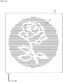
- the retaining elements 16 are counted on each of the lines L1 to L9 for a given pattern.
- the lines have the following numbers of retaining elements: L1: 4, L2: 8, L3: 9, L4: 10, L5: 11, L6: 12; L7:13, L8:12, L9:17.
- the pattern 12 as proposed thus presents at least two rows and/or two columns having distinct numbers of retaining elements. More generally, the pattern as proposed presents at least X rows and/or X columns of retention elements presenting distinct numbers of retention elements, with X equal to 2, or in certain cases equal to 3, or 4 , or 5, or more generally and Xmax can for example be equal to 500 or 450 or 400 or 350 or 300 or 250 or 200 or 150 or 100 or 50.
- At least two rows and/or columns have distinct numbers of retaining elements, the difference between the numbers of retaining elements of said two lines or two columns being greater than or equal to 1, or more precisely greater than or equal to 2, or even greater than or equal to 3 or 4 or 5.
- the pattern 12 is bordered by a rib 13 here forming a continuous contour around the pattern 14a.
- the rib 13 has a rectangular section.
- a rib 13 bordering the pattern 14a can have any section, and can be continuous or discontinuous.
- THE figures 8 to 11 present other examples of patterns that can be formed by the retaining elements and therefore by the cavities used for the formation of the retaining elements.
- zone devoid of retaining elements or cavities we understand a zone in which, respecting the pitch of the retaining elements or cavities, a retaining element or a cavity would normally have been present.
- the at least one zone devoid of retaining elements included in the zone delimited by the external contour of each pattern presents a dimension according to the primary direction DP strictly greater than twice the primary interval, and a dimension according to the secondary direction DS strictly greater than twice the secondary interval.
- the ratio of the second maximum dimension to the first maximum dimension is between 1.01 and 1.60, in particular between 1.01 and 1.35, more particularly between 1.02 and 1.15, in some cases between 1.03 and 1.12.
- the retainer is usually in the form of a ribbon whose length is in the primary direction DP or the secondary direction DS.
- a part of the tape according to the primary direction DP or the secondary direction DS is stuck on a paper of 80 g/cm 2 and a roll of 2 kg (kilogram) is applied or passed in rotation on the retainer is in one direction and then in the other (back and forth) along the entire length of the ribbon part.
- the paper and the retainer are cut using a cutting tool into strips of 25.4 mm (millimeter) width in the primary direction DP or the secondary direction DS at a speed of approximately 700 mm/ min (millimeter per minute).
- Each strip of paper has a length of 210 mm and the anti-slip strip is placed in the center of this strip.
- the sample of the application area has, for example depending on the size of the retainer, a width of 50 mm in the primary direction DP or the secondary direction DS and the length is maximum 200 mm and the sample is cut in half according to length.
- the assembly is then placed in a tensile testing machine including a 100 N (newton) measuring cell.
- the strip is inserted in the upper (movable) jaw.
- We set the reading of the force measuring cell to zero.
- the sample from the application area is inserted into the lower (fixed) jaw and slight tension is created.
- the force must be between 0.02 N and 0.05 N.
- the jaws are spaced 50 mm apart.
- the assembly is centered between the two jaws.
- the test is carried out at constant displacement at a speed of 305 mm/min and the test stroke is 50 mm. This test stroke is adapted according to the width of the retaining device to be tested.
- a line of cavities typically includes between 1 and 1000 cavities.
- a column of cavities typically includes between 1 and 1000 cavities.
- the cavities 102C are arranged so as to form patterns, typically disjoint, on the external face of the molding strip 102. Each pattern is formed by a plurality of rows and columns of cavities 102C.
- the different motives are typically disjoint.
- the different rows and columns are typically spaced regularly according to a transverse interval and a machine interval respectively.
- the transverse interval and the machine interval may be equal or distinct.
- said lines are spaced regularly according to a first transverse interval and according to a second transverse interval, the second transverse interval not being an integer multiple of the first transverse interval and the first transverse interval being less than the second transverse interval, and /or said columns are spaced regularly according to a first machine interval and according to a second machine interval, the second machine interval not being an integer multiple of the first machine interval and the first machine interval being less than the second machine interval.
- Each pattern is typically surrounded by a region of the external face of the molding strip devoid of retaining elements, said region having a dimension strictly greater than twice the machine interval in the machine direction MD, and/or strictly greater at twice the transverse interval in the transverse direction CD.
- the cavities 102C defining the rows and columns can be aligned or arranged in a staggered manner.
- the patterns formed by the cavities thus have at least two lines and/or two columns having distinct numbers of cavities. More generally, the pattern as proposed presents at least Y lines and/or Y columns of cavities presenting distinct numbers of cavities, with Y equal to 2, or in certain cases equal to 3 or 4 or 5, or more generally Y is a natural number between Ymin and Ymax, where Ymin can for example be equal to 2 or 3 or 4 or 5 or 6 or 7 or 8 or 9 or 10 or 12 or 15 or 20, and Ymax can for example be equal to 500 or 450 or 400 or 350 or 300 or 250 or 200 or 150 or 100 or 50.
- the variation in the number of cavities between said rows or columns of said pair is typically less than or equal to 10, or even less than or equal to 15.
Landscapes
- Engineering & Computer Science (AREA)
- Mechanical Engineering (AREA)
- Moulds For Moulding Plastics Or The Like (AREA)
- Slide Fasteners, Snap Fasteners, And Hook Fasteners (AREA)
- Moulding By Coating Moulds (AREA)
- Extrusion Moulding Of Plastics Or The Like (AREA)
- Solid-Sorbent Or Filter-Aiding Compositions (AREA)
- Absorbent Articles And Supports Therefor (AREA)
- Standing Axle, Rod, Or Tube Structures Coupled By Welding, Adhesion, Or Deposition (AREA)
Claims (18)
- Haltevorrichtung (10), umfassend:- eine Basis (12), die eine obere Seite (12A) und eine untere Seite (12B) aufweist, wobei die Basis (12) sich entlang einer Primärrichtung (DP) erstreckt, eine Breite, die entlang einer Sekundärrichtung (DS) senkrecht zur Primärrichtung (DP) definiert ist, und eine Dicke aufweist, die entlang einer Richtung senkrecht zur Primärrichtung (DP) und zur Sekundärrichtung (DS) gemessen wird,- mehrere Halteelemente (16), die sich auf der oberen Seite (12A) der Basis (12) erstrecken, wobei jedes Halteelement (16) einen Stab (18) umfasst, wobei die Halteelemente (16) einteilig mit der Basis (12) gebildet sind, wobei die Halteelemente (16) in Reihen und in Spalten angeordnet sind, die sich entlang der Sekundärrichtung (DS) beziehungsweise der Primärrichtung (DP) erstrecken,wobeimindestens X Reihen und/oder X Spalten der Haltevorrichtung verschiedene Anzahlen von Halteelementen (16) aufweisen, wobei X gleich 2 ist,die mehreren Halteelemente ein oder mehrere getrennte Motive bilden,jedes Motiv aus mehreren Reihen und Spalten von Halteelementen gebildet ist, wobei jedes Motiv durch einen äußeren Umriss (14A) abgegrenzt ist, und wobeijedes Motiv in der Zone, die durch seinen äußeren Umriss (14A) abgegrenzt ist, mindestens eine Zone ohne Halteelemente umfasst,wobei die Vorrichtung dadurch gekennzeichnet ist, dassfür jedes Motiv mindestens eine Zone ohne Halteelemente (16), die in dem Motiv beinhaltet ist, eine Breite und eine Länge aufweist, derart dass das Verhältnis zwischen der Länge und der Breite strikt größer als 1,2 ist.
- Haltevorrichtung (10) nach Anspruch 1, wobei mindestens zwei Reihen und/oder mindestens zwei Spalten der Haltevorrichtung eine verschiedene Anzahl von Halteelementen aufweisen, wobei die Differenz zwischen den Anzahlen von Halteelementen der mindestens zwei Reihen und/oder mindestens zwei Spalten größer oder gleich 1, oder, genauer gesagt, größer oder gleich 2 ist.
- Haltevorrichtung (10) nach einem der Ansprüche 1 oder 2, wobei für jedes Motiv jedes Paar aufeinanderfolgend entlang der Primärrichtung (DP) angeordneter Reihen eine Anzahl von Halteelementen aufweist, deren Veränderung kleiner oder gleich 10 Haltelemente ist, insbesondere kleiner oder gleich 5 Halteelemente ist.
- Haltevorrichtung (10) nach einem der Ansprüche 1 oder 3, wobei für jedes Motiv jedes Paar aufeinanderfolgend entlang der Sekundärrichtung (DS) angeordneter Spalten eine Anzahl von Haltelementen (16) aufweist, deren Veränderung kleiner oder gleich 15 Haltelemente (16) ist, insbesondere kleiner oder gleich 5 ist.
- Haltevorrichtung (10) nach einem der Ansprüche 1 bis 4, wobei jedes Motiv vollständig von einer Region der oberen Seite (12A) der Basis (12) ohne Haltelemente (16) umgeben ist und sich in einem Abstand von größer als 1,5 mm, insbesondere größer als 2,5 mm, ausgehend von einem Rand der Basis (12), insbesondere sämtlichen Rändern der Basis (12), befindet.
- Haltevorrichtung (10) nach Anspruch 5, wobei jedes Motiv mindestens eine Reihe und/oder mindestens eine Spalte aufweist, die mindestens zwei Gruppen von getrennten Halteelementen (16) umfasst, die durch eine Zone ohne Haltelemente (16) abgesondert sind.
- Haltevorrichtung (10) nach einem der Ansprüche 1 oder 6, wobei für jedes Motiv jede Zone ohne Halteelemente (16), die in dem Motiv beinhaltet ist, eine Breite und eine Länge aufweist, derart dass das Verhältnis zwischen der Länge und der Breite strikt größer als 1,2, oder insbesondere strikt größer als 1,5, ist.
- Haltevorrichtung (10) nach einem der Ansprüche 1 bis 7, wobei die Reihen und Spalten regelmäßig gemäß einem Sekundärintervall beziehungsweise einem Primärintervall beabstandet sind.
- Haltevorrichtung (10) nach Anspruch 8, wobei jedes Motiv vollständig von einer Region der oberen Seite (12A) der Basis (12) ohne Haltelemente (16) umgeben ist, wobei die Region eine Abmessung aufweist, die strikt größer als das Zweifache des Primärintervalls entlang der Primärrichtung (DP) und/oder strikt größer als das Zweifache des Sekundärintervalls entlang der Sekundärrichtung (DS) ist.
- Haltevorrichtung (10) nach Anspruch 1 bis 9, wobei die mindestens eine Zone ohne Haltelemente (16), die in der Zone umfasst ist, die durch den äußeren Umriss (14A) von jedem Motiv abgegrenzt ist, eine Abmessung entlang der Primärrichtung (DP), die strikt größer als das Zweifache des Primärintervalls ist, und eine Abmessung entlang der Sekundärrichtung (DS) aufweist, die strikt größer als das Zweifache des Sekundärintervalls ist.
- Haltevorrichtung (10) nach einem der Ansprüche 1 bis 10, wobei für jedes Motiv das Verhältnis zwischen der Oberfläche der Zonen ohne Haltelement (16), die in dem äußeren Umriss (14A) des Motivs enthalten sind, und der Oberfläche, die Halteelemente (16) umfasst, kleiner als 1 ist.
- Formvorrichtung (100) zur Bildung einer Haltevorrichtung, zum Beispiel nach einem der vorhergehenden Ansprüche, wobei die Formvorrichtung (100) ein Formband (102) umfasst, das geeignet ist, auf einem Träger (104) montiert zu sein, wobei das Formband (102) sich entlang einer Maschinenrichtung (MD) erstreckt, eine Breite, die entlang einer Querrichtung (CD) senkrecht zur Maschinenrichtung (MD) definiert ist, und eine Dicke, gemessen entlang einer Richtung senkrecht zur Maschinenrichtung (MD) und zur Querrichtung (CD), aufweist, wobei das Formband eine innere Seite und eine entgegengesetzte äußere Seite aufweist,wobei das Formband (102) mehrere Hohlräume (102C) aufweist, die in Reihen und in Spalten angeordnet sind, die sich entlang der Querrichtung (CD) beziehungsweise der Maschinenrichtung (MD) erstrecken, wobei die Hohlräume (102C) auf der äußeren Seite (102B) des Formbands (102) münden,wobeimindestens Y Reihen und/oder Y Spalten von Hohlräumen (102C) des Formbands (102) verschiedene Anzahlen von Hohlräumen (102C) aufweisen, wobei Y gleich 2 ist,die mehreren Hohlräume (102C) ein oder mehrere getrennte Motive bilden,jedes Motiv aus mehreren Reihen und Spalten von Hohlräumen (102C) gebildet ist, wobei jedes Motiv durch einen äußeren Umriss abgegrenzt ist, und wobei jedes Motiv in der Zone, die durch seinen äußeren Umriss abgegrenzt ist, mindestens eine Zone ohne Hohlräume (102C) umfasst,dadurch gekennzeichnet, dassfür jedes Motiv mindestens eine Zone ohne Hohlräume (102C), die in dem Motiv beinhaltet ist, eine Breite und eine Länge aufweist, derart dass das Verhältnis zwischen der Länge und der Breite strikt größer als 1,2 ist.
- Formvorrichtung (100) nach Anspruch 12, wobei mindestens zwei Reihen und/oder mindestens zwei Spalten der Formvorrichtung (100) eine verschiedene Anzahl von Hohlräumen (102C) aufweisen, wobei die Differenz zwischen den Anzahlen von Hohlräumen (102C) der mindestens zwei Reihen und/oder mindestens zwei Spalten größer oder gleich 1, oder genauer gesagt, größer oder gleich 2 ist.
- Formvorrichtung (100) nach einem der Ansprüche 12 oder 13, wobei für jedes Motiv jedes Paar aufeinanderfolgend entlang der Maschinenrichtung (MD) angeordneter Reihen eine Anzahl von Hohlräumen aufweist, deren Veränderung kleiner oder gleich 40 % der Höchstanzahl von Hohlräumen (102C) der Reihen des Paares von Reihen von Hohlräumen (102C), typischerweise kleiner oder gleich 30 % oder 15 %, ist.
- Formvorrichtung (100) nach einem der Ansprüche 12 bis 14, wobei jedes Motiv mindestens eine Reihe und/oder mindestens eine Spalte aufweist, die mindestens zwei Gruppen von getrennten Hohlräumen (102C) umfasst, die durch eine Zone ohne Hohlräume (102C) abgesondert sind.
- Formvorrichtung (100) nach einem der Ansprüche 12 bis 15, wobei für jedes Motiv jede Zone ohne Hohlräume (102C), die in dem Motiv beinhaltet ist, eine Breite und eine Länge aufweist, derart dass das Verhältnis zwischen der Länge und der Breite strikt größer als 1,2, insbesondere strikt größer als 1,5, ist.
- Formvorrichtung (100) nach einem der Ansprüche 12 bis 16, wobei die Spalten und Reihen regelmäßig entlang einem Querintervall beziehungsweise einem Maschinenintervall beabstandet sind.
- Formvorrichtung (100) nach Anspruch 17, wobei jedes Motiv vollständig von einer Region der äußeren Seite (102B) des Formbands (102) ohne Hohlräume (102C) umgeben ist, wobei die Region eine Abmessung aufweist, die strikt größer als das Zweifache des Maschinenintervalls entlang der Maschinenrichtung (MD) und strikt größer als das Zweifache des Querintervalls entlang der Querrichtung (CD) ist.
Priority Applications (1)
| Application Number | Priority Date | Filing Date | Title |
|---|---|---|---|
| EP24180031.7A EP4400283A3 (de) | 2019-12-11 | 2020-12-10 | Verbesserte selbstklebende vorrichtung und zugehörige formvorrichtung |
Applications Claiming Priority (3)
| Application Number | Priority Date | Filing Date | Title |
|---|---|---|---|
| FR1914165A FR3104388B1 (fr) | 2019-12-11 | 2019-12-11 | Dispositif auto-agrippant amélioré et dispositif de moulage associé. |
| FR1914162A FR3104387B1 (fr) | 2019-12-11 | 2019-12-11 | Bande de moulage et procédé de formation amélioré. |
| PCT/FR2020/052379 WO2021116612A1 (fr) | 2019-12-11 | 2020-12-10 | Dispositif auto-agrippant ameliore et dispositif de moulage associe |
Related Child Applications (2)
| Application Number | Title | Priority Date | Filing Date |
|---|---|---|---|
| EP24180031.7A Division EP4400283A3 (de) | 2019-12-11 | 2020-12-10 | Verbesserte selbstklebende vorrichtung und zugehörige formvorrichtung |
| EP24180031.7A Division-Into EP4400283A3 (de) | 2019-12-11 | 2020-12-10 | Verbesserte selbstklebende vorrichtung und zugehörige formvorrichtung |
Publications (2)
| Publication Number | Publication Date |
|---|---|
| EP4072371A1 EP4072371A1 (de) | 2022-10-19 |
| EP4072371B1 true EP4072371B1 (de) | 2024-07-10 |
Family
ID=74194771
Family Applications (3)
| Application Number | Title | Priority Date | Filing Date |
|---|---|---|---|
| EP20845169.0A Pending EP4072819A1 (de) | 2019-12-11 | 2020-12-10 | Formband und verbessertes verfahren zur herstellung |
| EP24180031.7A Pending EP4400283A3 (de) | 2019-12-11 | 2020-12-10 | Verbesserte selbstklebende vorrichtung und zugehörige formvorrichtung |
| EP20845168.2A Active EP4072371B1 (de) | 2019-12-11 | 2020-12-10 | Verbesserte selbstklebende vorrichtung und zugehörige formvorrichtung |
Family Applications Before (2)
| Application Number | Title | Priority Date | Filing Date |
|---|---|---|---|
| EP20845169.0A Pending EP4072819A1 (de) | 2019-12-11 | 2020-12-10 | Formband und verbessertes verfahren zur herstellung |
| EP24180031.7A Pending EP4400283A3 (de) | 2019-12-11 | 2020-12-10 | Verbesserte selbstklebende vorrichtung und zugehörige formvorrichtung |
Country Status (7)
| Country | Link |
|---|---|
| US (2) | US20230027363A1 (de) |
| EP (3) | EP4072819A1 (de) |
| JP (4) | JP2023506754A (de) |
| CN (2) | CN115135194B (de) |
| BR (1) | BR112022011165A2 (de) |
| ES (1) | ES2989983T3 (de) |
| WO (2) | WO2021116612A1 (de) |
Families Citing this family (1)
| Publication number | Priority date | Publication date | Assignee | Title |
|---|---|---|---|---|
| FR3140522B1 (fr) | 2022-10-11 | 2025-06-20 | Aplix Sa | Dispositif de retenue amélioré et procédé de fabrication associé |
Family Cites Families (20)
| Publication number | Priority date | Publication date | Assignee | Title |
|---|---|---|---|---|
| JP3308417B2 (ja) * | 1995-02-28 | 2002-07-29 | ワイケイケイ株式会社 | 成形面ファスナーのフック片構造 |
| JPH0994108A (ja) * | 1995-10-02 | 1997-04-08 | Ykk Corp | 装飾面を有する成形面ファスナー、並びにその製造装置及び製造方法 |
| US6280670B1 (en) * | 1997-08-22 | 2001-08-28 | Velcro Industries B.V. | Post- forming heads on fastener elements |
| US6258311B1 (en) * | 1997-08-25 | 2001-07-10 | Velcro Industries B.V. | Forming mold cavities |
| US6432339B1 (en) | 1997-08-25 | 2002-08-13 | Velcro Industries B.V. | Continuous molding of fastener products with a mold belt |
| ES2299479T3 (es) * | 2000-03-14 | 2008-06-01 | Velcro Industries B.V. | Cierre de gancho y presilla. |
| DE10039937A1 (de) | 2000-08-16 | 2002-03-07 | Binder Gottlieb Gmbh & Co | Verfahren zum Herstellen eines Haftverschlußteils |
| US6484371B1 (en) * | 2001-02-27 | 2002-11-26 | 3M Innovative Properties Company | High strength, flexible, light weight hook and loop bundling straps |
| DE60218660T2 (de) * | 2001-05-29 | 2007-11-08 | Velcro Industries B.V. | Herstellung von diskreten regionen mit verschlusselementen |
| US6687962B2 (en) * | 2002-01-16 | 2004-02-10 | Velcro Industries B.V. | Fastener element patterning |
| US6692674B1 (en) * | 2002-11-27 | 2004-02-17 | Velcro Industries B.V. | Discrete fastener regions |
| CN102065715A (zh) * | 2008-04-23 | 2011-05-18 | 可乐丽粘扣带股份有限公司 | 模内成形用卡止部件 |
| KR101315661B1 (ko) * | 2009-01-13 | 2013-10-08 | 와이케이케이 가부시끼가이샤 | 슬라이드 파스너 |
| CA2779810C (en) * | 2009-11-10 | 2014-07-22 | Velcro Industries B.V. | Releasable fastening along a bead |
| WO2011094474A1 (en) * | 2010-01-29 | 2011-08-04 | Velcro Industries B.V. | Temporary surface protection |
| DE112014002592T5 (de) * | 2013-05-28 | 2016-04-14 | The Procter & Gamble Company | Absorptionsartikel mit elastisch verlängerbarem Feld |
| US10687588B2 (en) * | 2014-10-22 | 2020-06-23 | 3M Innovative Properties Company | Printed components and methods for making the same |
| JP7094890B2 (ja) * | 2016-04-29 | 2022-07-04 | アプリックス | 強化保持要素を備える改良された保持具 |
| CN111629878B (zh) * | 2017-12-21 | 2022-09-27 | 维克罗知识产权控股有限责任公司 | 用于形成连续结构的模制设备和方法 |
| FR3077186B1 (fr) * | 2018-01-26 | 2020-01-31 | Aplix | Dispositif de retenue et ruban pour dispositif de retenue |
-
2020
- 2020-12-10 CN CN202080096182.0A patent/CN115135194B/zh active Active
- 2020-12-10 EP EP20845169.0A patent/EP4072819A1/de active Pending
- 2020-12-10 EP EP24180031.7A patent/EP4400283A3/de active Pending
- 2020-12-10 BR BR112022011165A patent/BR112022011165A2/pt unknown
- 2020-12-10 CN CN202080096181.6A patent/CN115066319A/zh active Pending
- 2020-12-10 JP JP2022535440A patent/JP2023506754A/ja active Pending
- 2020-12-10 JP JP2022535441A patent/JP7715712B2/ja active Active
- 2020-12-10 US US17/784,119 patent/US20230027363A1/en active Pending
- 2020-12-10 WO PCT/FR2020/052379 patent/WO2021116612A1/fr not_active Ceased
- 2020-12-10 US US17/783,761 patent/US20230011702A1/en active Pending
- 2020-12-10 ES ES20845168T patent/ES2989983T3/es active Active
- 2020-12-10 WO PCT/FR2020/052380 patent/WO2021116613A1/fr not_active Ceased
- 2020-12-10 EP EP20845168.2A patent/EP4072371B1/de active Active
-
2025
- 2025-02-21 JP JP2025026421A patent/JP2025081575A/ja active Pending
- 2025-05-07 JP JP2025077344A patent/JP2025114714A/ja active Pending
Also Published As
| Publication number | Publication date |
|---|---|
| JP7715712B2 (ja) | 2025-07-30 |
| CN115135194A (zh) | 2022-09-30 |
| JP2025114714A (ja) | 2025-08-05 |
| US20230027363A1 (en) | 2023-01-26 |
| JP2023506754A (ja) | 2023-02-20 |
| EP4072819A1 (de) | 2022-10-19 |
| EP4400283A2 (de) | 2024-07-17 |
| ES2989983T3 (es) | 2024-11-28 |
| WO2021116613A1 (fr) | 2021-06-17 |
| CN115135194B (zh) | 2026-01-27 |
| US20230011702A1 (en) | 2023-01-12 |
| EP4072371A1 (de) | 2022-10-19 |
| CN115066319A (zh) | 2022-09-16 |
| EP4400283A3 (de) | 2024-09-25 |
| JP2023506755A (ja) | 2023-02-20 |
| BR112022011165A2 (pt) | 2022-08-23 |
| JP2025081575A (ja) | 2025-05-27 |
| BR112022011167A2 (pt) | 2022-08-23 |
| WO2021116612A1 (fr) | 2021-06-17 |
Similar Documents
| Publication | Publication Date | Title |
|---|---|---|
| EP3448647B1 (de) | Vorrichtung und verfahren zur herstellung von halteelementen durch formen | |
| EP4072371B1 (de) | Verbesserte selbstklebende vorrichtung und zugehörige formvorrichtung | |
| FR3104387A1 (fr) | Bande de moulage et procédé de formation amélioré. | |
| FR3104388A1 (fr) | Dispositif auto-agrippant amélioré et dispositif de moulage associé. | |
| FR3050620B1 (fr) | Dispositif de retenue ameliore comprenant des elements de retenue renforces | |
| FR3050623B1 (fr) | Procede et appareillage ameliores pour la formation d'elements de retenue | |
| FR3050624B1 (fr) | Appareillage et procede ameliores pour la formation d'elements de retenue par formage | |
| FR3050621B1 (fr) | Dispositif de retenue ameliore a crochets presentant des bords ameliores | |
| EP4188148B1 (de) | Haltevorrichtung, saugfähiger artikel mit solch einer vorrichtung und verfahren zur herstellung solch einer vorrichtung | |
| FR3050625B1 (fr) | Dispositif de retenue a crochets ameliore | |
| FR3050622B1 (fr) | Appareillage et procede pour la solidarisation d'un substrat a un ruban plastique | |
| FR3140522A1 (fr) | Dispositif de retenue amélioré et procédé de fabrication associé |
Legal Events
| Date | Code | Title | Description |
|---|---|---|---|
| STAA | Information on the status of an ep patent application or granted ep patent |
Free format text: STATUS: UNKNOWN |
|
| STAA | Information on the status of an ep patent application or granted ep patent |
Free format text: STATUS: THE INTERNATIONAL PUBLICATION HAS BEEN MADE |
|
| PUAI | Public reference made under article 153(3) epc to a published international application that has entered the european phase |
Free format text: ORIGINAL CODE: 0009012 |
|
| STAA | Information on the status of an ep patent application or granted ep patent |
Free format text: STATUS: REQUEST FOR EXAMINATION WAS MADE |
|
| 17P | Request for examination filed |
Effective date: 20220517 |
|
| AK | Designated contracting states |
Kind code of ref document: A1 Designated state(s): AL AT BE BG CH CY CZ DE DK EE ES FI FR GB GR HR HU IE IS IT LI LT LU LV MC MK MT NL NO PL PT RO RS SE SI SK SM TR |
|
| DAV | Request for validation of the european patent (deleted) | ||
| DAX | Request for extension of the european patent (deleted) | ||
| P01 | Opt-out of the competence of the unified patent court (upc) registered |
Effective date: 20230513 |
|
| GRAP | Despatch of communication of intention to grant a patent |
Free format text: ORIGINAL CODE: EPIDOSNIGR1 |
|
| STAA | Information on the status of an ep patent application or granted ep patent |
Free format text: STATUS: GRANT OF PATENT IS INTENDED |
|
| INTG | Intention to grant announced |
Effective date: 20240216 |
|
| GRAS | Grant fee paid |
Free format text: ORIGINAL CODE: EPIDOSNIGR3 |
|
| GRAA | (expected) grant |
Free format text: ORIGINAL CODE: 0009210 |
|
| STAA | Information on the status of an ep patent application or granted ep patent |
Free format text: STATUS: THE PATENT HAS BEEN GRANTED |
|
| AK | Designated contracting states |
Kind code of ref document: B1 Designated state(s): AL AT BE BG CH CY CZ DE DK EE ES FI FR GB GR HR HU IE IS IT LI LT LU LV MC MK MT NL NO PL PT RO RS SE SI SK SM TR |
|
| REG | Reference to a national code |
Ref country code: CH Ref legal event code: EP |
|
| REG | Reference to a national code |
Ref country code: DE Ref legal event code: R096 Ref document number: 602020033871 Country of ref document: DE |
|
| REG | Reference to a national code |
Ref country code: LT Ref legal event code: MG9D |
|
| REG | Reference to a national code |
Ref country code: NL Ref legal event code: MP Effective date: 20240710 |
|
| REG | Reference to a national code |
Ref country code: ES Ref legal event code: FG2A Ref document number: 2989983 Country of ref document: ES Kind code of ref document: T3 Effective date: 20241128 |
|
| PG25 | Lapsed in a contracting state [announced via postgrant information from national office to epo] |
Ref country code: PT Free format text: LAPSE BECAUSE OF FAILURE TO SUBMIT A TRANSLATION OF THE DESCRIPTION OR TO PAY THE FEE WITHIN THE PRESCRIBED TIME-LIMIT Effective date: 20241111 |
|
| REG | Reference to a national code |
Ref country code: AT Ref legal event code: MK05 Ref document number: 1701215 Country of ref document: AT Kind code of ref document: T Effective date: 20240710 |
|
| PG25 | Lapsed in a contracting state [announced via postgrant information from national office to epo] |
Ref country code: NL Free format text: LAPSE BECAUSE OF FAILURE TO SUBMIT A TRANSLATION OF THE DESCRIPTION OR TO PAY THE FEE WITHIN THE PRESCRIBED TIME-LIMIT Effective date: 20240710 |
|
| PG25 | Lapsed in a contracting state [announced via postgrant information from national office to epo] |
Ref country code: PT Free format text: LAPSE BECAUSE OF FAILURE TO SUBMIT A TRANSLATION OF THE DESCRIPTION OR TO PAY THE FEE WITHIN THE PRESCRIBED TIME-LIMIT Effective date: 20241111 Ref country code: NL Free format text: LAPSE BECAUSE OF FAILURE TO SUBMIT A TRANSLATION OF THE DESCRIPTION OR TO PAY THE FEE WITHIN THE PRESCRIBED TIME-LIMIT Effective date: 20240710 |
|
| PG25 | Lapsed in a contracting state [announced via postgrant information from national office to epo] |
Ref country code: NO Free format text: LAPSE BECAUSE OF FAILURE TO SUBMIT A TRANSLATION OF THE DESCRIPTION OR TO PAY THE FEE WITHIN THE PRESCRIBED TIME-LIMIT Effective date: 20241010 |
|
| PG25 | Lapsed in a contracting state [announced via postgrant information from national office to epo] |
Ref country code: GR Free format text: LAPSE BECAUSE OF FAILURE TO SUBMIT A TRANSLATION OF THE DESCRIPTION OR TO PAY THE FEE WITHIN THE PRESCRIBED TIME-LIMIT Effective date: 20241011 Ref country code: FI Free format text: LAPSE BECAUSE OF FAILURE TO SUBMIT A TRANSLATION OF THE DESCRIPTION OR TO PAY THE FEE WITHIN THE PRESCRIBED TIME-LIMIT Effective date: 20240710 Ref country code: PL Free format text: LAPSE BECAUSE OF FAILURE TO SUBMIT A TRANSLATION OF THE DESCRIPTION OR TO PAY THE FEE WITHIN THE PRESCRIBED TIME-LIMIT Effective date: 20240710 |
|
| PG25 | Lapsed in a contracting state [announced via postgrant information from national office to epo] |
Ref country code: BG Free format text: LAPSE BECAUSE OF FAILURE TO SUBMIT A TRANSLATION OF THE DESCRIPTION OR TO PAY THE FEE WITHIN THE PRESCRIBED TIME-LIMIT Effective date: 20240710 |
|
| PG25 | Lapsed in a contracting state [announced via postgrant information from national office to epo] |
Ref country code: LV Free format text: LAPSE BECAUSE OF FAILURE TO SUBMIT A TRANSLATION OF THE DESCRIPTION OR TO PAY THE FEE WITHIN THE PRESCRIBED TIME-LIMIT Effective date: 20240710 |
|
| PG25 | Lapsed in a contracting state [announced via postgrant information from national office to epo] |
Ref country code: IS Free format text: LAPSE BECAUSE OF FAILURE TO SUBMIT A TRANSLATION OF THE DESCRIPTION OR TO PAY THE FEE WITHIN THE PRESCRIBED TIME-LIMIT Effective date: 20241110 Ref country code: AT Free format text: LAPSE BECAUSE OF FAILURE TO SUBMIT A TRANSLATION OF THE DESCRIPTION OR TO PAY THE FEE WITHIN THE PRESCRIBED TIME-LIMIT Effective date: 20240710 |
|
| PG25 | Lapsed in a contracting state [announced via postgrant information from national office to epo] |
Ref country code: HR Free format text: LAPSE BECAUSE OF FAILURE TO SUBMIT A TRANSLATION OF THE DESCRIPTION OR TO PAY THE FEE WITHIN THE PRESCRIBED TIME-LIMIT Effective date: 20240710 |
|
| PG25 | Lapsed in a contracting state [announced via postgrant information from national office to epo] |
Ref country code: RS Free format text: LAPSE BECAUSE OF FAILURE TO SUBMIT A TRANSLATION OF THE DESCRIPTION OR TO PAY THE FEE WITHIN THE PRESCRIBED TIME-LIMIT Effective date: 20241010 |
|
| PG25 | Lapsed in a contracting state [announced via postgrant information from national office to epo] |
Ref country code: RS Free format text: LAPSE BECAUSE OF FAILURE TO SUBMIT A TRANSLATION OF THE DESCRIPTION OR TO PAY THE FEE WITHIN THE PRESCRIBED TIME-LIMIT Effective date: 20241010 Ref country code: PL Free format text: LAPSE BECAUSE OF FAILURE TO SUBMIT A TRANSLATION OF THE DESCRIPTION OR TO PAY THE FEE WITHIN THE PRESCRIBED TIME-LIMIT Effective date: 20240710 Ref country code: NO Free format text: LAPSE BECAUSE OF FAILURE TO SUBMIT A TRANSLATION OF THE DESCRIPTION OR TO PAY THE FEE WITHIN THE PRESCRIBED TIME-LIMIT Effective date: 20241010 Ref country code: LV Free format text: LAPSE BECAUSE OF FAILURE TO SUBMIT A TRANSLATION OF THE DESCRIPTION OR TO PAY THE FEE WITHIN THE PRESCRIBED TIME-LIMIT Effective date: 20240710 Ref country code: IS Free format text: LAPSE BECAUSE OF FAILURE TO SUBMIT A TRANSLATION OF THE DESCRIPTION OR TO PAY THE FEE WITHIN THE PRESCRIBED TIME-LIMIT Effective date: 20241110 Ref country code: HR Free format text: LAPSE BECAUSE OF FAILURE TO SUBMIT A TRANSLATION OF THE DESCRIPTION OR TO PAY THE FEE WITHIN THE PRESCRIBED TIME-LIMIT Effective date: 20240710 Ref country code: GR Free format text: LAPSE BECAUSE OF FAILURE TO SUBMIT A TRANSLATION OF THE DESCRIPTION OR TO PAY THE FEE WITHIN THE PRESCRIBED TIME-LIMIT Effective date: 20241011 Ref country code: FI Free format text: LAPSE BECAUSE OF FAILURE TO SUBMIT A TRANSLATION OF THE DESCRIPTION OR TO PAY THE FEE WITHIN THE PRESCRIBED TIME-LIMIT Effective date: 20240710 Ref country code: BG Free format text: LAPSE BECAUSE OF FAILURE TO SUBMIT A TRANSLATION OF THE DESCRIPTION OR TO PAY THE FEE WITHIN THE PRESCRIBED TIME-LIMIT Effective date: 20240710 Ref country code: AT Free format text: LAPSE BECAUSE OF FAILURE TO SUBMIT A TRANSLATION OF THE DESCRIPTION OR TO PAY THE FEE WITHIN THE PRESCRIBED TIME-LIMIT Effective date: 20240710 |
|
| REG | Reference to a national code |
Ref country code: DE Ref legal event code: R097 Ref document number: 602020033871 Country of ref document: DE |
|
| PG25 | Lapsed in a contracting state [announced via postgrant information from national office to epo] |
Ref country code: DK Free format text: LAPSE BECAUSE OF FAILURE TO SUBMIT A TRANSLATION OF THE DESCRIPTION OR TO PAY THE FEE WITHIN THE PRESCRIBED TIME-LIMIT Effective date: 20240710 Ref country code: RO Free format text: LAPSE BECAUSE OF FAILURE TO SUBMIT A TRANSLATION OF THE DESCRIPTION OR TO PAY THE FEE WITHIN THE PRESCRIBED TIME-LIMIT Effective date: 20240710 Ref country code: SM Free format text: LAPSE BECAUSE OF FAILURE TO SUBMIT A TRANSLATION OF THE DESCRIPTION OR TO PAY THE FEE WITHIN THE PRESCRIBED TIME-LIMIT Effective date: 20240710 |
|
| PG25 | Lapsed in a contracting state [announced via postgrant information from national office to epo] |
Ref country code: EE Free format text: LAPSE BECAUSE OF FAILURE TO SUBMIT A TRANSLATION OF THE DESCRIPTION OR TO PAY THE FEE WITHIN THE PRESCRIBED TIME-LIMIT Effective date: 20240710 |
|
| PG25 | Lapsed in a contracting state [announced via postgrant information from national office to epo] |
Ref country code: CZ Free format text: LAPSE BECAUSE OF FAILURE TO SUBMIT A TRANSLATION OF THE DESCRIPTION OR TO PAY THE FEE WITHIN THE PRESCRIBED TIME-LIMIT Effective date: 20240710 |
|
| PG25 | Lapsed in a contracting state [announced via postgrant information from national office to epo] |
Ref country code: SK Free format text: LAPSE BECAUSE OF FAILURE TO SUBMIT A TRANSLATION OF THE DESCRIPTION OR TO PAY THE FEE WITHIN THE PRESCRIBED TIME-LIMIT Effective date: 20240710 Ref country code: IT Free format text: LAPSE BECAUSE OF FAILURE TO SUBMIT A TRANSLATION OF THE DESCRIPTION OR TO PAY THE FEE WITHIN THE PRESCRIBED TIME-LIMIT Effective date: 20240710 |
|
| PLBE | No opposition filed within time limit |
Free format text: ORIGINAL CODE: 0009261 |
|
| STAA | Information on the status of an ep patent application or granted ep patent |
Free format text: STATUS: NO OPPOSITION FILED WITHIN TIME LIMIT |
|
| 26N | No opposition filed |
Effective date: 20250411 |
|
| PG25 | Lapsed in a contracting state [announced via postgrant information from national office to epo] |
Ref country code: MC Free format text: LAPSE BECAUSE OF FAILURE TO SUBMIT A TRANSLATION OF THE DESCRIPTION OR TO PAY THE FEE WITHIN THE PRESCRIBED TIME-LIMIT Effective date: 20240710 |
|
| REG | Reference to a national code |
Ref country code: CH Ref legal event code: PL |
|
| PG25 | Lapsed in a contracting state [announced via postgrant information from national office to epo] |
Ref country code: LU Free format text: LAPSE BECAUSE OF NON-PAYMENT OF DUE FEES Effective date: 20241210 |
|
| GBPC | Gb: european patent ceased through non-payment of renewal fee |
Effective date: 20241210 |
|
| PG25 | Lapsed in a contracting state [announced via postgrant information from national office to epo] |
Ref country code: SE Free format text: LAPSE BECAUSE OF FAILURE TO SUBMIT A TRANSLATION OF THE DESCRIPTION OR TO PAY THE FEE WITHIN THE PRESCRIBED TIME-LIMIT Effective date: 20240710 |
|
| REG | Reference to a national code |
Ref country code: BE Ref legal event code: MM Effective date: 20241231 |
|
| PG25 | Lapsed in a contracting state [announced via postgrant information from national office to epo] |
Ref country code: BE Free format text: LAPSE BECAUSE OF NON-PAYMENT OF DUE FEES Effective date: 20241231 Ref country code: GB Free format text: LAPSE BECAUSE OF NON-PAYMENT OF DUE FEES Effective date: 20241210 |
|
| PG25 | Lapsed in a contracting state [announced via postgrant information from national office to epo] |
Ref country code: CH Free format text: LAPSE BECAUSE OF NON-PAYMENT OF DUE FEES Effective date: 20241231 |
|
| PG25 | Lapsed in a contracting state [announced via postgrant information from national office to epo] |
Ref country code: IE Free format text: LAPSE BECAUSE OF NON-PAYMENT OF DUE FEES Effective date: 20241210 |
|
| PGFP | Annual fee paid to national office [announced via postgrant information from national office to epo] |
Ref country code: FR Payment date: 20251218 Year of fee payment: 6 |
|
| PGFP | Annual fee paid to national office [announced via postgrant information from national office to epo] |
Ref country code: TR Payment date: 20251113 Year of fee payment: 6 |
|
| PGFP | Annual fee paid to national office [announced via postgrant information from national office to epo] |
Ref country code: ES Payment date: 20260112 Year of fee payment: 6 |
|
| PGFP | Annual fee paid to national office [announced via postgrant information from national office to epo] |
Ref country code: DE Payment date: 20251231 Year of fee payment: 6 |