EP4072426B1 - Extraction et présentation de caractéristique anatomique à l'aide de la réalité augmentée - Google Patents
Extraction et présentation de caractéristique anatomique à l'aide de la réalité augmentée Download PDFInfo
- Publication number
- EP4072426B1 EP4072426B1 EP20830039.2A EP20830039A EP4072426B1 EP 4072426 B1 EP4072426 B1 EP 4072426B1 EP 20830039 A EP20830039 A EP 20830039A EP 4072426 B1 EP4072426 B1 EP 4072426B1
- Authority
- EP
- European Patent Office
- Prior art keywords
- surgical
- pose
- patient
- data
- head
- Prior art date
- Legal status (The legal status is an assumption and is not a legal conclusion. Google has not performed a legal analysis and makes no representation as to the accuracy of the status listed.)
- Active
Links
Images







Classifications
-
- A—HUMAN NECESSITIES
- A61—MEDICAL OR VETERINARY SCIENCE; HYGIENE
- A61B—DIAGNOSIS; SURGERY; IDENTIFICATION
- A61B8/00—Diagnosis using ultrasonic, sonic or infrasonic waves
- A61B8/42—Details of probe positioning or probe attachment to the patient
- A61B8/4245—Details of probe positioning or probe attachment to the patient involving determining the position of the probe, e.g. with respect to an external reference frame or to the patient
-
- A—HUMAN NECESSITIES
- A61—MEDICAL OR VETERINARY SCIENCE; HYGIENE
- A61B—DIAGNOSIS; SURGERY; IDENTIFICATION
- A61B90/00—Instruments, implements or accessories specially adapted for surgery or diagnosis and not covered by any of the groups A61B1/00 - A61B50/00, e.g. for luxation treatment or for protecting wound edges
- A61B90/36—Image-producing devices or illumination devices not otherwise provided for
-
- A—HUMAN NECESSITIES
- A61—MEDICAL OR VETERINARY SCIENCE; HYGIENE
- A61B—DIAGNOSIS; SURGERY; IDENTIFICATION
- A61B34/00—Computer-aided surgery; Manipulators or robots specially adapted for use in surgery
- A61B34/10—Computer-aided planning, simulation or modelling of surgical operations
-
- A—HUMAN NECESSITIES
- A61—MEDICAL OR VETERINARY SCIENCE; HYGIENE
- A61B—DIAGNOSIS; SURGERY; IDENTIFICATION
- A61B34/00—Computer-aided surgery; Manipulators or robots specially adapted for use in surgery
- A61B34/20—Surgical navigation systems; Devices for tracking or guiding surgical instruments, e.g. for frameless stereotaxis
-
- A—HUMAN NECESSITIES
- A61—MEDICAL OR VETERINARY SCIENCE; HYGIENE
- A61B—DIAGNOSIS; SURGERY; IDENTIFICATION
- A61B8/00—Diagnosis using ultrasonic, sonic or infrasonic waves
- A61B8/08—Clinical applications
- A61B8/0875—Clinical applications for diagnosis of bone
-
- A—HUMAN NECESSITIES
- A61—MEDICAL OR VETERINARY SCIENCE; HYGIENE
- A61B—DIAGNOSIS; SURGERY; IDENTIFICATION
- A61B8/00—Diagnosis using ultrasonic, sonic or infrasonic waves
- A61B8/42—Details of probe positioning or probe attachment to the patient
- A61B8/4245—Details of probe positioning or probe attachment to the patient involving determining the position of the probe, e.g. with respect to an external reference frame or to the patient
- A61B8/4263—Details of probe positioning or probe attachment to the patient involving determining the position of the probe, e.g. with respect to an external reference frame or to the patient using sensors not mounted on the probe, e.g. mounted on an external reference frame
-
- A—HUMAN NECESSITIES
- A61—MEDICAL OR VETERINARY SCIENCE; HYGIENE
- A61B—DIAGNOSIS; SURGERY; IDENTIFICATION
- A61B8/00—Diagnosis using ultrasonic, sonic or infrasonic waves
- A61B8/46—Ultrasonic, sonic or infrasonic diagnostic devices with special arrangements for interfacing with the operator or the patient
- A61B8/461—Displaying means of special interest
-
- A—HUMAN NECESSITIES
- A61—MEDICAL OR VETERINARY SCIENCE; HYGIENE
- A61B—DIAGNOSIS; SURGERY; IDENTIFICATION
- A61B8/00—Diagnosis using ultrasonic, sonic or infrasonic waves
- A61B8/46—Ultrasonic, sonic or infrasonic diagnostic devices with special arrangements for interfacing with the operator or the patient
- A61B8/461—Displaying means of special interest
- A61B8/462—Displaying means of special interest characterised by constructional features of the display
-
- A—HUMAN NECESSITIES
- A61—MEDICAL OR VETERINARY SCIENCE; HYGIENE
- A61B—DIAGNOSIS; SURGERY; IDENTIFICATION
- A61B8/00—Diagnosis using ultrasonic, sonic or infrasonic waves
- A61B8/46—Ultrasonic, sonic or infrasonic diagnostic devices with special arrangements for interfacing with the operator or the patient
- A61B8/461—Displaying means of special interest
- A61B8/466—Displaying means of special interest adapted to display 3D data
-
- A—HUMAN NECESSITIES
- A61—MEDICAL OR VETERINARY SCIENCE; HYGIENE
- A61B—DIAGNOSIS; SURGERY; IDENTIFICATION
- A61B8/00—Diagnosis using ultrasonic, sonic or infrasonic waves
- A61B8/46—Ultrasonic, sonic or infrasonic diagnostic devices with special arrangements for interfacing with the operator or the patient
- A61B8/467—Ultrasonic, sonic or infrasonic diagnostic devices with special arrangements for interfacing with the operator or the patient characterised by special input means
- A61B8/469—Ultrasonic, sonic or infrasonic diagnostic devices with special arrangements for interfacing with the operator or the patient characterised by special input means for selection of a region of interest
-
- A—HUMAN NECESSITIES
- A61—MEDICAL OR VETERINARY SCIENCE; HYGIENE
- A61B—DIAGNOSIS; SURGERY; IDENTIFICATION
- A61B8/00—Diagnosis using ultrasonic, sonic or infrasonic waves
- A61B8/48—Diagnostic techniques
- A61B8/483—Diagnostic techniques involving the acquisition of a 3D volume of data
-
- A—HUMAN NECESSITIES
- A61—MEDICAL OR VETERINARY SCIENCE; HYGIENE
- A61B—DIAGNOSIS; SURGERY; IDENTIFICATION
- A61B8/00—Diagnosis using ultrasonic, sonic or infrasonic waves
- A61B8/52—Devices using data or image processing specially adapted for diagnosis using ultrasonic, sonic or infrasonic waves
- A61B8/5215—Devices using data or image processing specially adapted for diagnosis using ultrasonic, sonic or infrasonic waves involving processing of medical diagnostic data
- A61B8/5238—Devices using data or image processing specially adapted for diagnosis using ultrasonic, sonic or infrasonic waves involving processing of medical diagnostic data for combining image data of patient, e.g. merging several images from different acquisition modes into one image
- A61B8/5246—Devices using data or image processing specially adapted for diagnosis using ultrasonic, sonic or infrasonic waves involving processing of medical diagnostic data for combining image data of patient, e.g. merging several images from different acquisition modes into one image combining images from the same or different imaging techniques, e.g. color Doppler and B-mode
-
- A—HUMAN NECESSITIES
- A61—MEDICAL OR VETERINARY SCIENCE; HYGIENE
- A61B—DIAGNOSIS; SURGERY; IDENTIFICATION
- A61B8/00—Diagnosis using ultrasonic, sonic or infrasonic waves
- A61B8/52—Devices using data or image processing specially adapted for diagnosis using ultrasonic, sonic or infrasonic waves
- A61B8/5215—Devices using data or image processing specially adapted for diagnosis using ultrasonic, sonic or infrasonic waves involving processing of medical diagnostic data
- A61B8/5238—Devices using data or image processing specially adapted for diagnosis using ultrasonic, sonic or infrasonic waves involving processing of medical diagnostic data for combining image data of patient, e.g. merging several images from different acquisition modes into one image
- A61B8/5261—Devices using data or image processing specially adapted for diagnosis using ultrasonic, sonic or infrasonic waves involving processing of medical diagnostic data for combining image data of patient, e.g. merging several images from different acquisition modes into one image combining images from different diagnostic modalities, e.g. ultrasound and X-ray
-
- A—HUMAN NECESSITIES
- A61—MEDICAL OR VETERINARY SCIENCE; HYGIENE
- A61B—DIAGNOSIS; SURGERY; IDENTIFICATION
- A61B90/00—Instruments, implements or accessories specially adapted for surgery or diagnosis and not covered by any of the groups A61B1/00 - A61B50/00, e.g. for luxation treatment or for protecting wound edges
- A61B90/39—Markers, e.g. radio-opaque or breast lesions markers
-
- G—PHYSICS
- G06—COMPUTING OR CALCULATING; COUNTING
- G06F—ELECTRIC DIGITAL DATA PROCESSING
- G06F3/00—Input arrangements for transferring data to be processed into a form capable of being handled by the computer; Output arrangements for transferring data from processing unit to output unit, e.g. interface arrangements
- G06F3/01—Input arrangements or combined input and output arrangements for interaction between user and computer
- G06F3/011—Arrangements for interaction with the human body, e.g. for user immersion in virtual reality
-
- G—PHYSICS
- G06—COMPUTING OR CALCULATING; COUNTING
- G06F—ELECTRIC DIGITAL DATA PROCESSING
- G06F3/00—Input arrangements for transferring data to be processed into a form capable of being handled by the computer; Output arrangements for transferring data from processing unit to output unit, e.g. interface arrangements
- G06F3/01—Input arrangements or combined input and output arrangements for interaction between user and computer
- G06F3/03—Arrangements for converting the position or the displacement of a member into a coded form
- G06F3/0304—Detection arrangements using opto-electronic means
-
- G—PHYSICS
- G06—COMPUTING OR CALCULATING; COUNTING
- G06F—ELECTRIC DIGITAL DATA PROCESSING
- G06F3/00—Input arrangements for transferring data to be processed into a form capable of being handled by the computer; Output arrangements for transferring data from processing unit to output unit, e.g. interface arrangements
- G06F3/01—Input arrangements or combined input and output arrangements for interaction between user and computer
- G06F3/03—Arrangements for converting the position or the displacement of a member into a coded form
- G06F3/033—Pointing devices displaced or positioned by the user, e.g. mice, trackballs, pens or joysticks; Accessories therefor
- G06F3/0346—Pointing devices displaced or positioned by the user, e.g. mice, trackballs, pens or joysticks; Accessories therefor with detection of the device orientation or free movement in a three-dimensional [3D] space, e.g. 3D mice, 6-DOF [six degrees of freedom] pointers using gyroscopes, accelerometers or tilt-sensors
-
- G—PHYSICS
- G06—COMPUTING OR CALCULATING; COUNTING
- G06T—IMAGE DATA PROCESSING OR GENERATION, IN GENERAL
- G06T19/00—Manipulating three-dimensional [3D] models or images for computer graphics
- G06T19/006—Mixed reality
-
- G—PHYSICS
- G06—COMPUTING OR CALCULATING; COUNTING
- G06T—IMAGE DATA PROCESSING OR GENERATION, IN GENERAL
- G06T7/00—Image analysis
- G06T7/10—Segmentation; Edge detection
- G06T7/13—Edge detection
-
- G—PHYSICS
- G06—COMPUTING OR CALCULATING; COUNTING
- G06T—IMAGE DATA PROCESSING OR GENERATION, IN GENERAL
- G06T7/00—Image analysis
- G06T7/10—Segmentation; Edge detection
- G06T7/149—Segmentation; Edge detection involving deformable models, e.g. active contour models
-
- G—PHYSICS
- G06—COMPUTING OR CALCULATING; COUNTING
- G06V—IMAGE OR VIDEO RECOGNITION OR UNDERSTANDING
- G06V10/00—Arrangements for image or video recognition or understanding
- G06V10/40—Extraction of image or video features
- G06V10/44—Local feature extraction by analysis of parts of the pattern, e.g. by detecting edges, contours, loops, corners, strokes or intersections; Connectivity analysis, e.g. of connected components
-
- A—HUMAN NECESSITIES
- A61—MEDICAL OR VETERINARY SCIENCE; HYGIENE
- A61B—DIAGNOSIS; SURGERY; IDENTIFICATION
- A61B34/00—Computer-aided surgery; Manipulators or robots specially adapted for use in surgery
- A61B34/10—Computer-aided planning, simulation or modelling of surgical operations
- A61B2034/101—Computer-aided simulation of surgical operations
- A61B2034/105—Modelling of the patient, e.g. for ligaments or bones
-
- A—HUMAN NECESSITIES
- A61—MEDICAL OR VETERINARY SCIENCE; HYGIENE
- A61B—DIAGNOSIS; SURGERY; IDENTIFICATION
- A61B34/00—Computer-aided surgery; Manipulators or robots specially adapted for use in surgery
- A61B34/20—Surgical navigation systems; Devices for tracking or guiding surgical instruments, e.g. for frameless stereotaxis
- A61B2034/2046—Tracking techniques
- A61B2034/2055—Optical tracking systems
-
- A—HUMAN NECESSITIES
- A61—MEDICAL OR VETERINARY SCIENCE; HYGIENE
- A61B—DIAGNOSIS; SURGERY; IDENTIFICATION
- A61B34/00—Computer-aided surgery; Manipulators or robots specially adapted for use in surgery
- A61B34/20—Surgical navigation systems; Devices for tracking or guiding surgical instruments, e.g. for frameless stereotaxis
- A61B2034/2046—Tracking techniques
- A61B2034/2063—Acoustic tracking systems, e.g. using ultrasound
-
- A—HUMAN NECESSITIES
- A61—MEDICAL OR VETERINARY SCIENCE; HYGIENE
- A61B—DIAGNOSIS; SURGERY; IDENTIFICATION
- A61B90/00—Instruments, implements or accessories specially adapted for surgery or diagnosis and not covered by any of the groups A61B1/00 - A61B50/00, e.g. for luxation treatment or for protecting wound edges
- A61B90/36—Image-producing devices or illumination devices not otherwise provided for
- A61B2090/364—Correlation of different images or relation of image positions in respect to the body
- A61B2090/365—Correlation of different images or relation of image positions in respect to the body augmented reality, i.e. correlating a live optical image with another image
-
- A—HUMAN NECESSITIES
- A61—MEDICAL OR VETERINARY SCIENCE; HYGIENE
- A61B—DIAGNOSIS; SURGERY; IDENTIFICATION
- A61B90/00—Instruments, implements or accessories specially adapted for surgery or diagnosis and not covered by any of the groups A61B1/00 - A61B50/00, e.g. for luxation treatment or for protecting wound edges
- A61B90/36—Image-producing devices or illumination devices not otherwise provided for
- A61B2090/364—Correlation of different images or relation of image positions in respect to the body
- A61B2090/367—Correlation of different images or relation of image positions in respect to the body creating a 3D dataset from 2D images using position information
-
- A—HUMAN NECESSITIES
- A61—MEDICAL OR VETERINARY SCIENCE; HYGIENE
- A61B—DIAGNOSIS; SURGERY; IDENTIFICATION
- A61B90/00—Instruments, implements or accessories specially adapted for surgery or diagnosis and not covered by any of the groups A61B1/00 - A61B50/00, e.g. for luxation treatment or for protecting wound edges
- A61B90/39—Markers, e.g. radio-opaque or breast lesions markers
- A61B2090/3937—Visible markers
Definitions
- the present disclosure relates generally to methods, systems, and apparatuses related to a computer-assisted surgical system that includes on augmented reality headset to enhance surgical workflows.
- the disclosed system techniques may be applied to systems that utilize intraoperative imaging to enhance anatomical understanding.
- Some workflows rely on providing a surgeon with preoperative imaging data to develop a detailed surgical plan before the procedure begins.
- Some surgical workflows use imaging systems in the surgical theater, such as ultrasound imaging, to supplement preoperative imaging (or to supplement what the surgeon can see with the naked eye during surgery).
- intraoperative imaging can be useful for providing additional intelligence about patient anatomy
- intraoperative imaging can be difficult to introduce efficiently into a surgical workflow. Namely, surgery requires intense concentration by a surgeon. Providing a standalone imaging system that requires a surgeon to look away from the patient to see imaging can reduce efficiency, distract the surgeon, and it can be difficult for a surgeon to orient/correlate the imaging relative to the physical patient.
- surgeries may require multiple personnel, each of whom may benefit from the intraoperative imaging, but the imaging may be disorienting to anyone in the surgical theater not holding an imaging device, such as an ultrasound probe. It is desirable to maintain surgical staff attention on the patient while minimizing distraction. This goal is often frustrated by the introduction of intraoperative imaging.
- Ultrasound uses sound waves to create images of soft tissue structures in order to examine the interior anatomy of a patient.
- a real-time ultrasound image displays white and shades of gray/black.
- Bright (white) shaded areas depict denser tissue structures, with the brightest white being bone.
- Darker shaded areas indicate less dense structures with black indicating a lack of structure, especially fluid.
- AR headsets HMDs
- medical imaging to AR HMDs in a medical setting.
- these efforts typically involve displaying an entire ultrasound image, which includes large amounts of extraneous visual noise, including large dark or bright areas that could obstruct a viewer's vision of the patient and provide additional distraction.
- these images may be presented using a virtual screen while viewing the patient, but these images are not meaningfully correlated to the patient in the field-of-view.
- an ultrasound of the leg may be displayed floating next to a patient, but the wearer of the HMD will need to mentally map that medical image to the anatomy of the patient in front of them. Further, any movement of the patient or the probe results in added difficulty to relate the location of a structure in an ultrasound image to a location in the patient.
- US 2019349559 A1 describes a real-time surgery method and apparatus for displaying an augmented view of a patient from a static or dynamic viewpoint of the surgeon.
- a surgical system comprising: an ultrasound system comprising an ultrasound probe configured to obtain a two-dimensional ultrasound image of a surgical site; a head-mounted display; a tracking system configured to determine a pose of the ultrasound probe; and a computer system configured to: receive the two-dimensional ultrasound image from the ultrasound system, extract a feature from the two-dimensional ultrasound image, the feature associated with an anatomical structure at the surgical site, determine the pose of the ultrasound probe via the tracking system, update a three-dimensional feature model associated with the anatomical structure with the extracted feature based on the determined pose of the ultrasound probe, determine where features of the updated three-dimensional feature model are located relative to a field of view of the head-mounted display, and display the features of the updated three-dimensional feature model that are located within the field of view of the head-mounted display.
- the head-mounted display comprises the computer system.
- the head-mounted display comprises the tracking system.
- the pose of the ultrasound probe is determined relative to the head-mounted display.
- the pose comprises a first pose
- the tracking system is further configured to determine a second pose of the head-mounted display
- the computer system is further configured to: determine the second pose of the head-mounted display via the tracking system, determine a relative pose of the ultrasound probe relative to the head-mounted display based on the determined first pose of the ultrasound probe and the determined second pose of the head-mounted display, and determine where features of the updated three-dimensional feature model are located relative to the field of view of the head-mounted display based on the relative pose of the ultrasound probe.
- the computer system is further configured to: determine whether any of the features of the updated three-dimensional feature model are older than a threshold time period; and remove the features of the updated three-dimensional feature model that are older than the threshold time period from the field of view of the head-mounted display.
- the feature comprises a boundary of the anatomical structure.
- a computer-implemented method of displaying an anatomical structure via a head-mounted display using an ultrasound system comprising an ultrasound probe configured to obtain a two-dimensional ultrasound image of a surgical site and a tracking system configured to determine a pose of the ultrasound probe, the method comprising: receiving, by a computer system, the two-dimensional ultrasound image from the ultrasound system, extracting, by the computer system, a feature from the two-dimensional ultrasound image, the feature associated with an anatomical structure at the surgical site; determining, by the computer system, the pose of the ultrasound probe via the tracking system; updating, by the computer system, a three-dimensional feature model associated with the anatomical structure with the extracted feature based on the determined pose of the ultrasound probe; determining, by the computer system, where features of the updated three-dimensional feature model are located relative to a field of view of the head-mounted display; and displaying, by the computer system the features of the updated three-dimensional feature model that are located within the field of view of the head-mounted display.
- the pose comprises a first pose
- the tracking system is further configured to determine a second pose of the head-mounted display
- the method further comprises: determining, by the computer system, the second pose of the head-mounted display via the tracking system, determining, by the computer system, a relative pose of the ultrasound probe relative to the head-mounted display based on the determined first pose of the ultrasound probe and the determined second pose of the head-mounted display, and determining, by the computer system, where features of the updated three-dimensional feature model are located relative to the field of view of the head-mounted display based on the relative pose of the ultrasound probe.
- the method further comprises: determining, by the computer system, whether any of the features of the updated three-dimensional feature model are older than a threshold time period; and removing, by the computer system, the features of the updated three-dimensional feature model that are older than the threshold time period from the field of view of the head-mounted display.
- the term "implant” is used to refer to a prosthetic device or structure manufactured to replace or enhance a biological structure.
- a prosthetic acetabular cup (implant) is used to replace or enhance a patients worn or damaged acetabulum.
- implant is generally considered to denote a man-made structure (as contrasted with a transplant), for the purposes of this specification an implant can include a biological tissue or material transplanted to replace or enhance a biological structure.
- real-time is used to refer to calculations or operations performed on-the-fly as events occur or input is received by the operable system.
- real-time is not intended to preclude operations that cause some latency between input and response, so long as the latency is an unintended consequence induced by the performance characteristics of the machine.
- NAVIO is a registered trademark of BLUE BELT TECHNOLOGIES, INC. of Pittsburgh, PA, which is a subsidiary of SMITH & NEPHEW, INC. of Memphis, TN.
- FIG. 1 provides an illustration of an example computer-assisted surgical system (CASS) 100, according to some embodiments.
- the CASS uses computers, robotics, and imaging technology to aid surgeons in performing orthopedic surgery procedures such as total knee arthroplasty (TKA) or total hip arthroplasty (THA).
- TKA total knee arthroplasty
- THA total hip arthroplasty
- surgical navigation systems can aid surgeons in locating patient anatomical structures, guiding surgical instruments, and implanting medical devices with a high degree of accuracy.
- Surgical navigation systems such as the CASS 100 often employ various forms of computing technology to perform a wide variety of standard and minimally invasive surgical procedures and techniques.
- these systems allow surgeons to more accurately plan, track and navigate the placement of instruments and implants relative to the body of a patient, as well as conduct pre-operative and intra-operative body imaging.
- An Effector Platform 105 positions surgical tools relative to a patient during surgery.
- the exact components of the Effector Platform 105 will vary, depending on the embodiment employed.
- the Effector Platform 105 may include an End Effector 105B that holds surgical tools or instruments during their use.
- the End Effector 105B may be a handheld device or instrument used by the surgeon (e.g., a NAVIO ® hand piece or a cutting guide or jig) or, alternatively, the End Effector 105B can include a device or instrument held or positioned by a Robotic Arm 105A. While one Robotic Arm 105A is illustrated in FIG. 1 , in some embodiments there may be multiple devices.
- the Effector Platform 105 may include tools, such as a screwdriver, light or laser, to indicate an axis or plane, bubble level, pin driver, pin puller, plane checker, pointer, finger, or some combination thereof.
- tools such as a screwdriver, light or laser, to indicate an axis or plane, bubble level, pin driver, pin puller, plane checker, pointer, finger, or some combination thereof.
- the Effector Platform 105 also can include a cutting guide or jig 105D that is used to guide saws or drills used to resect tissue during surgery.
- Such cutting guides 105D can be formed integrally as part of the Effector Platform 105 or Robotic Arm 105A, or cutting guides can be separate structures that can be matingly and/or removably attached to the Effector Platform 105 or Robotic Arm 105A.
- the Effector Platform 105 or Robotic Arm 105A can be controlled by the CASS 100 to position a cutting guide or jig 105D adjacent to the patient's anatomy in accordance with a pre-operatively or intraoperatively developed surgical plan such that the cutting guide or jig will produce a precise bone cut in accordance with the surgical plan.
- EM electromagnetic
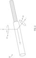
- sensor 200 may be able to track/determine movement in the X, Y, or Z direction, as well as rotation around the Y-axis 202 or Z-axis 201.
- sensor 200 may be able to track/determine movement in the X, Y, or Z direction, as well as rotation around the Y-axis 202 or Z-axis 201.
- because of the electromagnetic properties of a coil it is not possible to properly track rotational movement around the X axis.
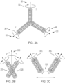
- a three coil system such as that shown in FIG. 3A is used to enable tracking in all six degrees of freedom that are possible for a rigid body moving in a three-dimensional space (i.e., forward/backward 310, up/down 320, left/right 330, roll 340, pitch 350, and yaw 360).
- the inclusion of two additional coils and the 90° offset angles at which they are positioned may require the tracking device to be much larger.
- less than three full coils may be used to track all 6DOF.
- two coils may be affixed to each other, such as is shown in FIG. 3B . Because the two coils 301B and 302B are rigidly affixed to each other, not perfectly parallel, and have locations that are known relative to each other, it is possible to determine the sixth degree of freedom 303B with this arrangement.
- the sensor device is substantially larger in diameter than a single coil because of the additional coil.
- the practical application of using an EM based tracking system in a surgical environment may require tissue resection and drilling of a portion of the patient bone to allow for insertion of a EM tracker.
- a solution is needed for which the use of an EM tracking system can be restricted to devices small enough to be inserted/embedded using a small diameter needle or pin (i.e., without the need to create a new incision or large diameter opening in the bone).
- a second 5DOF sensor which is not attached to the first, and thus has a small diameter, may be used to track all 6DOF.
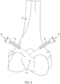
- two 5DOF EM sensors may be inserted into the patient (e.g., in a patient bone) at different locations and with different angular orientations (e.g., angle 303C is non-zero).
- first 5DOF EM sensor 401 and a second 5DOF EM sensor 402 are inserted into the patient bone 403 using a standard hollow needle 405 that is typical in most OR(s).
- first sensor 401 and the second sensor 402 may have an angle offset of " ⁇ " 404.
- a minimum value may be based on one or more factors, such as, for example, the orientation accuracy of the tracking system, a distance between the first and second EM sensors.
- a pin/needle e.g., a cannulated mounting needle, etc.
- the pin/needle would be a disposable component, while the sensors themselves may be reusable.
- the EM sensors may be affixed to the mounting needle/pin (e.g., using a luer-lock fitting or the like), which can allow for quick assembly and disassembly.
- the EM sensors may utilize an alternative sleeve and/or anchor system that allows for minimally invasive placement of the sensors.
- certain markers such as fiducial marks that identify individuals, important tools, or bones in the theater may include passive or active identifiers that can be picked up by a camera or camera array associated with the tracking system.
- an IR LED can flash a pattern that conveys a unique identifier to the source of that pattern, providing a dynamic identification mark.
- one or two dimensional optical codes can be affixed to objects in the theater to provide passive identification that can occur based on image analysis. If these codes are placed asymmetrically on an object, they also can be used to determine an orientation of an object by comparing the location of the identifier with the extents of an object in an image.
- certain features of objects can be tracked by registering physical properties of the object and associating them with objects that can be tracked, such as fiducial marks fixed to a tool or bone.
- objects such as fiducial marks fixed to a tool or bone.
- a surgeon may perform a manual registration process whereby a tracked tool and a tracked bone can be manipulated relative to one another.
- a three-dimensional surface can be mapped for that bone that is associated with a position and orientation relative to the frame of reference of that fiducial mark.
- a model of that surface can be tracked with an environment through extrapolation.
- a Tissue Navigation System 120 (not shown in FIG. 1 ) provides the surgeon with intraoperative, real-time visualization for the patient's bone, cartilage, muscle, nervous, and/or vascular tissues surrounding the surgical area.
- tissue navigation examples include fluorescent imaging systems and ultrasound systems.
- the Display 125 provides graphical user interfaces (GUIs) that display images collected by the Tissue Navigation System 120 as well other information relevant to the surgery.
- GUIs graphical user interfaces
- the Display 125 overlays image information collected from various modalities (e.g., CT, MRI, X-ray, fluorescent, ultrasound, etc.) collected pre-operatively or intra-operatively to give the surgeon various views of the patient's anatomy as well as real-time conditions.
- the Display 125 may include, for example, one or more computer monitors.
- one or more members of the surgical staff may wear an Augmented Reality (AR) Head Mounted Device (HMD).
- AR Augmented Reality
- FIG. 1 the Surgeon 111 is wearing an AR HMD 155 that may, for example, overlay pre-operative image data on the patient or provide surgical planning suggestions.
- AR HMD 155 may, for example, overlay pre-operative image data on the patient or provide surgical planning suggestions.
- Surgical Computer 150 provides control instructions to various components of the CASS 100, collects data from those components, and provides general processing for various data needed during surgery.
- the Surgical Computer 150 is a general purpose computer.
- the Surgical Computer 150 may be a parallel computing platform that uses multiple central processing units (CPUs) or graphics processing units (GPU) to perform processing.
- the Surgical Computer 150 is connected to a remote server over one or more computer networks (e.g., the Internet).
- the remote server can be used, for example, for storage of data or execution of computationally intensive processing tasks.
- the patient's anatomy can be registered to the CASS 100 using CT or other image data, the identification of anatomical landmarks, tracker arrays attached to the patient's bones, and one or more cameras.
- Tracker arrays can be mounted on the iliac crest using clamps and/or bone pins and such trackers can be mounted externally through the skin or internally (either posterolaterally or anterolaterally) through the incision made to perform the THA.
- the CASS 100 can utilize one or more femoral cortical screws inserted into the proximal femur as checkpoints to aid in the registration process.
- the CASS 100 can provide the surgeon with an option to turn off or disengage the robotic control of the reamer.
- the display 125 can depict the progress of the bone being resected (reamed) as compared to the surgical plan using different colors.
- the surgeon can view the display of the bone being resected (reamed) to guide the reamer to complete the reaming in accordance with the surgical plan.
- the CASS 100 can provide visual or audible prompts to the surgeon to warn the surgeon that resections are being made that are not in accordance with the surgical plan.
- the CASS-developed surgical plan can be viewed preoperatively and intraoperatively, and the surgeon can modify CASS-developed surgical plan preoperatively or intraoperatively.
- the CASS-developed surgical plan can display the planned resection to the hip joint and superimpose the planned implants onto the hip joint based on the planned resections.
- the CASS 100 can provide the surgeon with options for different surgical workflows that will be displayed to the surgeon based on a surgeon's preference. For example, the surgeon can choose from different workflows based on the number and types of anatomical landmarks that are checked and captured and/or the location and number of tracker arrays used in the registration process.
- a powered impaction device used with the CASS 100 may operate with a variety of different settings.
- the surgeon adjusts settings through a manual switch or other physical mechanism on the powered impaction device.
- a digital interface may be used that allows setting entry, for example, via a touchscreen on the powered impaction device. Such a digital interface may allow the available settings to vary based, for example, on the type of attachment piece connected to the power attachment device.
- the settings can be changed through communication with a robot or other computer system within the CASS 100. Such connections may be established using, for example, a Bluetooth or Wi-Fi networking module on the powered impaction device.
- the impaction device and end pieces may contain features that allow the impaction device to be aware of what end piece (cup impactor, broach handle, etc.) is attached with no action required by the surgeon, and adjust the settings accordingly. This may be achieved, for example, through a QR code, barcode, RFID tag, or other method.
- the settings include cup impaction settings (e.g., single direction, specified frequency range, specified force and/or energy range); broach impaction settings (e.g., dual direction/oscillating at a specified frequency range, specified force and/or energy range); femoral head impaction settings (e.g., single direction/single blow at a specified force or energy); and stem impaction settings (e.g., single direction at specified frequency with a specified force or energy).
- the powered impaction device includes settings related to acetabular liner impaction (e.g., single direction/single blow at a specified force or energy).
- the powered impaction device may offer settings for different bone quality based on preoperative testing/imaging/knowledge and/or intraoperative assessment by surgeon.
- the powered impactor device may have a dual function. For example, the powered impactor device not only could provide reciprocating motion to provide an impact force, but also could provide reciprocating motion for a broach or rasp.
- the powered impaction device includes feedback sensors that gather data during instrument use and send data to a computing device, such as a controller within the device or the Surgical Computer 150.
- This computing device can then record the data for later analysis and use.
- Examples of the data that may be collected include, without limitation, sound waves, the predetermined resonance frequency of each instrument, reaction force or rebound energy from patient bone, location of the device with respect to imaging (e.g., fluoro, CT, ultrasound, MRI, etc.) registered bony anatomy, and/or external strain gauges on bones.
- the computing device may execute one or more algorithms in real-time or near real-time to aid the surgeon in performing the surgical procedure. For example, in some embodiments, the computing device uses the collected data to derive information such as the proper final broach size (femur); when the stem is fully seated (femur side); or when the cup is seated (depth and/or orientation) for a THA. Once the information is known, it may be displayed for the surgeon's review, or it may be used to activate haptics or other feedback mechanisms to guide the surgical procedure.
- information such as the proper final broach size (femur); when the stem is fully seated (femur side); or when the cup is seated (depth and/or orientation) for a THA.
- the data derived from the aforementioned algorithms may be used to drive operation of the device.
- the device may automatically extend an impaction head (e.g., an end effector) moving the implant into the proper location, or turn the power off to the device once the implant is fully seated.
- the derived information may be used to automatically adjust settings for quality of bone where the powered impaction device should use less power to mitigate femoral/acetabular/pelvic fracture or damage to surrounding tissues.
- the CASS 100 includes a robotic arm 105A that serves as an interface to stabilize and hold a variety of instruments used during the surgical procedure.
- these instruments may include, without limitation, retractors, a sagittal or reciprocating saw, the reamer handle, the cup impactor, the broach handle, and the stem inserter.
- the robotic arm 105A may have multiple degrees of freedom (like a Spider device), and have the ability to be locked in place (e.g., by a press of a button, voice activation, a surgeon removing a hand from the robotic arm, or other method).
- movement of the robotic arm 105A may be effectuated by use of a control panel built into the robotic arm system.
- a display screen may include one or more input sources, such as physical buttons or a user interface having one or more icons, that direct movement of the robotic arm 105A.
- the surgeon or other healthcare professional may engage with the one or more input sources to position the robotic arm 105A when performing a surgical procedure.
- a tool or an end effector 105B attached or integrated into a robotic arm 105A may include, without limitation, a burring device, a scalpel, a cutting device, a retractor, a joint tensioning device, or the like.
- the end effector may be positioned at the end of the robotic arm 105A such that any motor control operations are performed within the robotic arm system.
- the tool may be secured at a distal end of the robotic arm 105A, but motor control operation may reside within the tool itself.
- the robotic arm 105A may be motorized internally to both stabilize the robotic arm, thereby preventing it from falling and hitting the patient, surgical table, surgical staff, etc., and to allow the surgeon to move the robotic arm without having to fully support its weight. While the surgeon is moving the robotic arm 105A, the robotic arm may provide some resistance to prevent the robotic arm from moving too fast or having too many degrees of freedom active at once.
- the position and the lock status of the robotic arm 105A may be tracked, for example, by a controller or the Surgical Computer 150.
- the movement of the robotic arm 105A or robotically controlled end effector 105B can be controlled remotely by a surgeon or other medical professional using a control mechanism separate from the robotic arm or robotically controlled end effector device, for example using a joystick or interactive monitor or display control device.
- ACL anterior cruciate ligament
- a robotic arm 105A may be used for holding the retractor.
- the robotic arm 105A may be moved into the desired position by the surgeon. At that point, the robotic arm 105A may lock into place.
- the robotic arm 105A is provided with data regarding the patient's position, such that if the patient moves, the robotic arm can adjust the retractor position accordingly.
- multiple robotic arms may be used, thereby allowing multiple retractors to be held or for more than one activity to be performed simultaneously (e.g., retractor holding & reaming).
- the robotic arm 105A may also be used to help stabilize the surgeon's hand while making a femoral neck cut.
- control of the robotic arm 105A may impose certain restrictions to prevent soft tissue damage from occurring.
- the Surgical Computer 150 tracks the position of the robotic arm 105A as it operates. If the tracked location approaches an area where tissue damage is predicted, a command may be sent to the robotic arm 105A causing it to stop.
- the robotic arm 105A is automatically controlled by the Surgical Computer 150, the Surgical Computer may ensure that the robotic arm is not provided with any instructions that cause it to enter areas where soft tissue damage is likely to occur.
- the Surgical Computer 150 may impose certain restrictions on the surgeon to prevent the surgeon from reaming too far into the medial wall of the acetabulum or reaming at an incorrect angle or orientation.
- the robotic arm 105A may be used to hold a cup impactor at a desired angle or orientation during cup impaction. When the final position has been achieved, the robotic arm 105A may prevent any further seating to prevent damage to the pelvis.
- the surgeon may use the robotic arm 105A to position the broach handle at the desired position and allow the surgeon to impact the broach into the femoral canal at the desired orientation.
- the robotic arm 105A may restrict the handle to prevent further advancement of the broach.
- the robotic arm 105A may also be used for resurfacing applications.
- the robotic arm 105A may stabilize the surgeon while using traditional instrumentation and provide certain restrictions or limitations to allow for proper placement of implant components (e.g., guide wire placement, chamfer cutter, sleeve cutter, plan cutter, etc.).
- implant components e.g., guide wire placement, chamfer cutter, sleeve cutter, plan cutter, etc.
- the robotic arm 105A may stabilize the surgeon's handpiece and may impose restrictions on the handpiece to prevent the surgeon from removing unintended bone in contravention of the surgical plan.
- the robotic arm 105A may be a passive arm.
- the robotic arm 105A may be a CIRQ robot arm available from Brainlab AG.
- CIRQ is a registered trademark of Brainlab AG, Olof-Palme-Str. 9 81829, Ober, FED REP of GERMANY.
- the robotic arm 105A is an intelligent holding arm as disclosed in U.S. Patent Application No. 15/525,585 to Krinninger et al. , U.S. Patent Application No. 15/561,042 to Nowatschin et al. , U.S. Patent Application No. 15/561,048 to Nowatschin et al. , and U.S. Patent No. 10,342,636 to Nowatschin et al. , the entire contents of each of which is herein incorporated by reference.
- the various services that are provided by medical professionals to treat a clinical condition are collectively referred to as an "episode of care.”
- the episode of care can include three phases: pre-operative, intra-operative, and post-operative.
- data is collected or generated that can be used to analyze the episode of care in order to understand various features of the procedure and identify patterns that may be used, for example, in training models to make decisions with minimal human intervention.
- the data collected over the episode of care may be stored at the Surgical Computer 150 or the Surgical Data Server 180 as a complete dataset.
- implants can be designed using episode of care data.
- Example data-driven techniques for designing, sizing, and fitting implants are described in U.S. Patent Application No. 13/814,531 filed August 15, 2011 and entitled “Systems and Methods for Optimizing Parameters for Orthopaedic Procedures"; U.S. Patent Application No. 14/232,958 filed July 20, 2012 and entitled “Systems and Methods for Optimizing Fit of an Implant to Anatomy”; and U.S. Patent Application No. 12/234,444 filed September 19, 2008 and entitled “Operatively Tuning Implants for Increased Performance,".
- the data can be used for educational, training, or research purposes.
- other doctors or students can remotely view surgeries in interfaces that allow them to selectively view data as it is collected from the various components of the CASS 100.
- similar interfaces may be used to "playback" a surgery for training or other educational purposes, or to identify the source of any issues or complications with the procedure.
- Data acquired during the pre-operative phase generally includes all information collected or generated prior to the surgery.
- information about the patient may be acquired from a patient intake form or electronic medical record (EMR).
- patient information that may be collected include, without limitation, patient demographics, diagnoses, medical histories, progress notes, vital signs, medical history information, allergies, and lab results.
- EMR electronic medical record
- patient information that may be collected include, without limitation, patient demographics, diagnoses, medical histories, progress notes, vital signs, medical history information, allergies, and lab results.
- the pre-operative data may also include images related to the anatomical area of interest. These images may be captured, for example, using Magnetic Resonance Imaging (MRI), Computed Tomography (CT), X-ray, ultrasound, or any other modality known in the art.
- the pre-operative data may also comprise quality of life data captured from the patient.
- cutting guide 105D can be fixed to the femoral head or the acetabulum for the respective hip arthroplasty resection. It should be understood that any arthroplasty that utilizes precise cuts can use the robotic arm 105A and/or cutting guide 105D in this manner.
- the Resection Equipment 110 is provided with a variety of commands to perform bone or tissue operations. As with the Effector Platform 105, position information may be provided to the Resection Equipment 110 to specify where it should be located when performing resection. Other commands provided to the Resection Equipment 110 may be dependent on the type of resection equipment. For example, for a mechanical or ultrasonic resection tool, the commands may specify the speed and frequency of the tool. For Radiofrequency Ablation (RFA) and other laser ablation tools, the commands may specify intensity and pulse duration.
- RFA Radiofrequency Ablation
- the commands may specify intensity and pulse duration.
- Some components of the CASS 100 do not need to be directly controlled by the Surgical Computer 150; rather, the Surgical Computer 150 only needs to activate the component, which then executes software locally specifying the manner in which to collect data and provide it to the Surgical Computer 150.
- the Tracking System 115 and the Tissue Navigation System 120.
- the Surgical Computer 150 provides the Display 125 with any visualization that is needed by the Surgeon 111 during surgery.
- the Surgical Computer 150 may provide instructions for displaying images, GUIs, etc. using techniques known in the art.
- the display 125 can include various portions of the workflow of a surgical plan. During the registration process, for example, the display 125 can show a preoperatively constructed 3D bone model and depict the locations of the probe as the surgeon uses the probe to collect locations of anatomical landmarks on the patient.
- the display 125 can include information about the surgical target area. For example, in connection with a TKA, the display 125 can depict the mechanical and anatomical axes of the femur and tibia.
- the display 125 can depict varus and valgus angles for the knee joint based on a surgical plan, and the CASS 100 can depict how such angles will be affected if contemplated revisions to the surgical plan are made. Accordingly, the display 125 is an interactive interface that can dynamically update and display how changes to the surgical plan would impact the procedure and the final position and orientation of implants installed on bone.
- the display 125 can depict the planned or recommended bone cuts before any cuts are performed.
- the surgeon 111 can manipulate the image display to provide different anatomical perspectives of the target area and can have the option to alter or revise the planned bone cuts based on intraoperative evaluation of the patient.
- the display 125 can depict how the chosen implants would be installed on the bone if the planned bone cuts are performed. If the surgeon 111 choses to change the previously planned bone cuts, the display 125 can depict how the revised bone cuts would change the position and orientation of the implant when installed on the bone.
- the display 125 can provide the surgeon 111 with a variety of data and information about the patient, the planned surgical intervention, and the implants. Various patient-specific information can be displayed, including real-time data concerning the patient's health such as heart rate, blood pressure, etc.
- the display 125 also can include information about the anatomy of the surgical target region including the location of landmarks, the current state of the anatomy (e.g., whether any resections have been made, the depth and angles of planned and executed bone cuts), and future states of the anatomy as the surgical plan progresses.
- the display 125 also can provide or depict additional information about the surgical target region.
- the display 125 can provide information about the gaps (e.g., gap balancing) between the femur and tibia and how such gaps will change if the planned surgical plan is carried out.
- the display 125 can provide additional relevant information about the knee joint such as data about the joint's tension (e.g., ligament laxity) and information concerning rotation and alignment of the joint.
- the display 125 can depict how the planned implants' locations and positions will affect the patient as the knee joint is flexed.
- the display 125 can depict how the use of different implants or the use of different sizes of the same implant will affect the surgical plan and preview how such implants will be positioned on the bone.
- the CASS 100 can provide such information for each of the planned bone resections in a TKA or THA.
- the CASS 100 can provide robotic control for one or more of the planned bone resections.
- the CASS 100 can provide robotic control only for the initial distal femur cut, and the surgeon 111 can manually perform other resections (anterior, posterior and chamfer cuts) using conventional means, such as a 4-in-1 cutting guide or jig 105D.
- the display 125 can employ different colors to inform the surgeon of the status of the surgical plan. For example, un-resected bone can be displayed in a first color, resected bone can be displayed in a second color, and planned resections can be displayed in a third color. Implants can be superimposed onto the bone in the display 125, and implant colors can change or correspond to different types or sizes of implants.
- the information and options depicted on the display 125 can vary depending on the type of surgical procedure being performed. Further, the surgeon 111 can request or select a particular surgical workflow display that matches or is consistent with his or her surgical plan preferences. For example, for a surgeon 111 who typically performs the tibial cuts before the femoral cuts in a TKA, the display 125 and associated workflow can be adapted to take this preference into account. The surgeon 111 also can preselect that certain steps be included or deleted from the standard surgical workflow display.
- the surgical workflow display can be organized into modules, and the surgeon can select which modules to display and the order in which the modules are provided based on the surgeon's preferences or the circumstances of a particular surgery.
- Modules directed to ligament and gap balancing can include pre- and post-resection ligament/gap balancing, and the surgeon 111 can select which modules to include in their default surgical plan workflow depending on whether they perform such ligament and gap balancing before or after (or both) bone resections are performed.
- the Surgical Computer 150 may provide images, text, etc. using the data format supported by the equipment.
- the Display 125 is a holography device such as the Microsoft HoloLens TM or Magic Leap One TM
- the Surgical Computer 150 may use the HoloLens Application Program Interface (API) to send commands specifying the position and content of holograms displayed in the field of view of the Surgeon 111.
- API HoloLens Application Program Interface
- the CASS 100 is designed to operate as an "open" digital ecosystem.
- components may be produced by a variety of different companies according to standards for activities, such as communication, storage, and security. Thus, by using these standards, any company can freely build an independent, compliant component of the CASS platform. Data may be transferred between components using publicly available application programming interfaces (APIs) and open, shareable data formats.
- APIs application programming interfaces
- optimization in this context means selection of parameters that are optimal based on certain specified criteria.
- optimization can refer to selecting optimal parameter(s) based on data from the entire episode of care, including any pre-operative data, the state of CASS data at a given point in time, and post-operative goals.
- optimization may be performed using historical data, such as data generated during past surgeries involving, for example, the same surgeon, past patients with physical characteristics similar to the current patient, or the like.
- the optimized parameters may depend on the portion of the patient's anatomy to be operated on.
- the surgical parameters may include positioning information for the femoral and tibial component including, without limitation, rotational alignment (e.g., varus/valgus rotation, external rotation, flexion rotation for the femoral component, posterior slope of the tibial component), resection depths (e.g., varus knee, valgus knee), and implant type, size and position.
- the positioning information may further include surgical parameters for the combined implant, such as overall limb alignment, combined tibiofemoral hyperextension, and combined tibiofemoral resection.
- parameters that could be optimized for a given TKA femoral implant by the CASS 100 include the following: Parameter Reference Exemplary Recommendation (s) Size Posterior The largest sized implant that does not overhang medial/lateral bone edges or overhang the anterior femur.
- Additional examples of parameters that could be optimized for a given TKA tibial implant by the CASS 100 include the following: Parameter Reference Exemplary Recommendation (s) Size Posterior The largest sized implant that does not overhang the medial, lateral, anterior, and posterior tibial edges Implant Position Medial/lateral and anterior/posterior cortical bone edges Center the implant evenly between the medial/lateral and anterior/posterior cortical bone edges Resection Depth - Varus Knee Lateral/Medial 4 mm of bone Resection Depth - Valgus Knee Lateral/Medial 5 mm of bone Rotation - Varus/Valgus Mechanical Axis 1° valgus Rotation - External Tibial Anterior Posterior Axis 1° external from the tibial anterior paxis Posterior Slope Mechanical Axis 3° posterior slope
- the surgical parameters may comprise femoral neck resection location and angle, cup inclination angle, cup anteversion angle, cup depth, femoral stem design, femoral stem size, fit of the femoral stem within the canal, femoral offset, leg length, and femoral version of the implant.
- Shoulder parameters may include, without limitation, humeral resection depth/angle, humeral stem version, humeral offset, glenoid version and inclination, as well as reverse shoulder parameters such as humeral resection depth/angle, humeral stem version, Glenoid tilt/version, glenosphere orientation, glenosphere offset and offset direction.
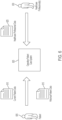
- the general concepts of optimization may be extended to the entire episode of care using an Operative Patient Care System 620 that uses the surgical data, and other data from the Patient 605 and Healthcare Professionals 630 to optimize outcomes and patient satisfaction as depicted in FIG. 6 .
- pre-operative diagnosis, pre-operative surgical planning, intra-operative execution of a prescribed plan, and post-operative management of total joint arthroplasty are based on individual experience, published literature, and training knowledge bases of surgeons (ultimately, tribal knowledge of individual surgeons and their 'network' of peers and journal publications) and their native ability to make accurate intra-operative tactile discernment of "balance" and accurate manual execution of planar resections using guides and visual cues.
- This existing knowledge base and execution is limited with respect to the outcomes optimization offered to patients needing care.
- the Operative Patient Care System 620 is designed to utilize patient specific data, surgeon data, healthcare facility data, and historical outcome data to develop an algorithm that suggests or recommends an optimal overall treatment plan for the patient's entire episode of care (preoperative, operative, and postoperative) based on a desired clinical outcome. For example, in one embodiment, the Operative Patient Care System 620 tracks adherence to the suggested or recommended plan, and adapts the plan based on patient/care provider performance. Once the surgical treatment plan is complete, collected data is logged by the Operative Patient Care System 620 in a historical database. This database is accessible for future patients and the development of future treatment plans.
- a Patient 605 provides inputs such as Current Patient Data 610 and Historical Patient Data 615 to the Operative Patient Care System 620.
- Various methods generally known in the art may be used to gather such inputs from the Patient 605.
- the Patient 605 fills out a paper or digital survey that is parsed by the Operative Patient Care System 620 to extract patient data.
- the Operative Patient Care System 620 may extract patient data from existing information sources, such as electronic medical records (EMRs), health history files, and payer/provider historical files.
- EMRs electronic medical records
- the Operative Patient Care System 620 may provide an application program interface (API) that allows the external data source to push data to the Operative Patient Care System.
- API application program interface
- Current Patient Data 610 can include, but is not limited to, activity level, preexisting conditions, comorbidities, prehab performance, health and fitness level, pre-operative expectation level (relating to hospital, surgery, and recovery), a Metropolitan Statistical Area (MSA) driven score, genetic background, prior injuries (sports, trauma, etc.), previous joint arthroplasty, previous trauma procedures, previous sports medicine procedures, treatment of the contralateral joint or limb, gait or biomechanical information (back and ankle issues), levels of pain or discomfort, care infrastructure information (payer coverage type, home health care infrastructure level, etc.), and an indication of the expected ideal outcome of the procedure.
- MSA Metropolitan Statistical Area
- This Healthcare Professional Data 625 may include, for example, a description of a known or preferred surgical technique (e.g., Cruciate Retaining (CR) vs Posterior Stabilized (PS), up- vs downsizing, tourniquet vs tourniquet-less, femoral stem style, preferred approach for THA, etc.), the level of training of the Healthcare Professional(s) 630 (e.g., years in practice, fellowship trained, where they trained, whose techniques they emulate), previous success level including historical data (outcomes, patient satisfaction), and the expected ideal outcome with respect to range of motion, days of recovery, and survivorship of the device.
- a known or preferred surgical technique e.g., Cruciate Retaining (CR) vs Posterior Stabilized (PS), up- vs downsizing, tourniquet vs tourniquet-less, femoral stem style, preferred approach for THA, etc.
- the level of training of the Healthcare Professional(s) 630 e
- the Healthcare Professional Data 625 can be captured, for example, with paper or digital surveys provided to the Healthcare Professional 630, via inputs to a mobile application by the Healthcare Professional, or by extracting relevant data from EMRs.
- the CASS 100 may provide data such as profile data (e.g., a Patient Specific Knee Instrument Profile) or historical logs describing use of the CASS during surgery.
- Information pertaining to the facility where the procedure or treatment will be conducted may be included in the input data.
- This data can include, without limitation, the following: Ambulatory Surgery Center (ASC) vs hospital, facility trauma level, Comprehensive Care for Joint Replacement Program (CJR) or bundle candidacy, a MSA driven score, community vs metro, academic vs non-academic, postoperative network access (Skilled Nursing Facility [SNF] only, Home Health, etc.), availability of medical professionals, implant availability, and availability of surgical equipment.
- ASC Ambulatory Surgery Center
- CJR Comprehensive Care for Joint Replacement Program
- MSA driven score a MSA driven score
- community vs metro community vs metro
- academic vs non-academic academic vs non-academic
- postoperative network access Skilled Nursing Facility [SNF] only, Home Health, etc.
- Input data relating to the associated healthcare economy including, but not limited to, the socioeconomic profile of the patient, the expected level of reimbursement the patient will receive, and if the treatment is patient specific may also be captured.
- Simulation inputs include implant size, position, and orientation. Simulation can be conducted with custom or commercially available anatomical modeling software programs (e.g., LIFEMOD ® , AnyBody, or OpenSIM). It is noted that the data inputs described above may not be available for every patient, and the treatment plan will be generated using the data that is available.
- the Patient Data 610, 615 and Healthcare Professional Data 625 may be captured and stored in a cloud-based or online database (e.g., the Surgical Data Server 180 shown in FIG. 5C ).
- Information relevant to the procedure is supplied to a computing system via wireless data transfer or manually with the use of portable media storage.
- the computing system is configured to generate a case plan for use with a CASS 100. Case plan generation will be described hereinafter. It is noted that the system has access to historical data from previous patients undergoing treatment, including implant size, placement, and orientation as generated by a computer-assisted, patient-specific knee instrument (PSKI) selection system, or automatically by the CASS 100 itself. To achieve this, case log data is uploaded to the historical database by a surgical sales rep or case engineer using an online portal. In some embodiments, data transfer to the online database is wireless and automated.
- PSKI patient-specific knee instrument
- the predictor equation and associated optimization can be used to generate the resection planes for use with a PSKI system.
- the predictor equation computation and optimization are completed prior to surgery.
- Patient anatomy is estimated using medical image data (x-ray, CT, MRI).
- Global optimization of the predictor equation can provide an ideal size and position of the implant components.
- Boolean intersection of the implant components and patient anatomy is defined as the resection volume.
- PSKI can be produced to remove the optimized resection envelope. In this embodiment, the surgeon cannot alter the surgical plan intraoperatively.
- the surgeon may choose to alter the surgical case plan at any time prior to or during the procedure. If the surgeon elects to deviate from the surgical case plan, the altered size, position, and/or orientation of the component(s) is locked, and the global optimization is refreshed based on the new size, position, and/or orientation of the component(s) (using the techniques previously described) to find the new ideal position of the other component(s) and the corresponding resections needed to be performed to achieve the newly optimized size, position and/or orientation of the component(s).
- the femoral implant position is locked relative to the anatomy, and the new optimal position of the tibia will be calculated (via global optimization) considering the surgeon's changes to the femoral implant size, position and/or orientation.
- the surgical system used to implement the case plan is robotically assisted (e.g., as with NAVIO ® or the MAKO Rio)
- bone removal and bone morphology during the surgery can be monitored in real time. If the resections made during the procedure deviate from the surgical plan, the subsequent placement of additional components may be optimized by the processor taking into account the actual resections that have already been made.
- the case plan from the previous patient can be accessed and adapted or adopted for use with the current patient.
- the predictor equation may be used in conjunction with an intra-operative algorithm that identifies or determines the actions associated with the case plan. Based on the relevant and/or preselected information from the historical database, the intra-operative algorithm determines a series of recommended actions for the surgeon to perform. Each execution of the algorithm produces the next action in the case plan. If the surgeon performs the action, the results are evaluated. The results of the surgeon's performing the action are used to refine and update inputs to the intra-operative algorithm for generating the next step in the case plan.
- the system utilizes preoperative, intraoperative, or postoperative modules in a piecewise fashion, as opposed to the entire continuum of care.
- caregivers can prescribe any permutation or combination of treatment modules including the use of a single module.
- a GUI that provides a visual depiction of the knee during tissue resection may provide the measured torque and displacement of the resection equipment adjacent to the visual depiction to better provide an understanding of any deviations that occurred from the planned resection area.
- the ability to review a playback of the surgical plan or toggle between different phases of the actual surgery vs. the surgical plan could provide benefits to the surgeon and/or surgical staff, allowing such persons to identify any deficiencies or challenging phases of a surgery so that they can be modified in future surgeries.
- the aforementioned GUIs can be used as a teaching tool for training future surgeons and/or surgical staff.
- the data set effectively records many elements of the surgeon's activity, it may also be used for other reasons (e.g., legal or compliance reasons) as evidence of correct or incorrect performance of a particular surgical procedure.
- Training of the machine learning model can be performed as follows.
- the overall state of the CASS 100 can be sampled over a plurality of time periods for the duration of the surgery.
- the machine learning model can then be trained to translate a current state at a first time period to a future state at a different time period.
- a plurality of machine learning models may be used rather than a single model.
- the machine learning model may be trained not only with the state of the CASS 100, but also with patient data (e.g., captured from an EMR) and an identification of members of the surgical staff. This allows the model to make predictions with even greater specificity. Moreover, it allows surgeons to selectively make predictions based only on their own surgical experiences if desired.
- predictions or recommendations made by the aforementioned machine learning models can be directly integrated into the surgical workflow.
- the Surgical Computer 150 may execute the machine learning model in the background making predictions or recommendations for upcoming actions or surgical conditions. A plurality of states can thus be predicted or recommended for each period.
- the Surgical Computer 150 may predict or recommend the state for the next 5 minutes in 30 second increments.
- the surgeon can utilize a "process display" view of the surgery that allows visualization of the future state.
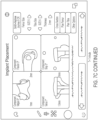
- FIG. 7C depicts a series of images that may be displayed to the surgeon depicting the implant placement interface.
- the surgeon can cycle through these images, for example, by entering a particular time into the display 125 of the CASS 100 or instructing the system to advance or rewind the display in a specific time increment using a tactile, oral, or other instruction.
- the process display can be presented in the upper portion of the surgeon's field of view in the AR HMD.
- the process display can be updated in real-time. For example, as the surgeon moves resection tools around the planned resection area, the process display can be updated so that the surgeon can see how his or her actions are affecting the other factors of the surgery.
- various elements of the surgery can be automated such that the surgeon only needs to be minimally involved, for example, by only providing approval for various steps of the surgery.
- robotic control using arms or other means can be gradually integrated into the surgical workflow over time with the surgeon slowly becoming less and less involved with manual interaction versus robot operation.
- the machine learning model in this case can learn what robotic commands are required to achieve certain states of the CASS-implemented plan.
- the machine learning model may be used to produce a film strip or similar view or display that predicts and can preview the entire surgery from an initial state.
- an initial state may be defined that includes the patient information, the surgical plan, implant characteristics, and surgeon preferences.
- the surgeon could preview an entire surgery to confirm that the CASS-recommended plan meets the surgeon's expectations and/or requirements.
- the output of the machine learning model is the state of the CASS 100 itself, commands can be derived to control the components of the CASS to achieve each predicted state. In the extreme case, the entire surgery could thus be automated based on just the initial state information.
- an optically tracked point probe may be used to map the actual surface of the target bone that needs a new implant. Mapping is performed after removal of the defective or worn-out implant, as well as after removal of any diseased or otherwise unwanted bone. A plurality of points is collected on the bone surfaces by brushing or scraping the entirety of the remaining bone with the tip of the point probe. This is referred to as tracing or "painting" the bone. The collected points are used to create a three-dimensional model or surface map of the bone surfaces in the computerized planning system.
- the Dorr Classification helps to select a stem that will maximize the ability of achieving a press-fit during surgery to prevent micromotion of femoral components post-surgery and ensure optimal bony ingrowth.
- the Dorr Classification measures the ratio between the canal width at the LT and the canal width 10 cm below the LT. The accuracy of the classification is highly dependent on the correct location of the relevant anatomy. Thus, it may be advantageous to paint the LT to provide a high-resolution view of the area.
- the HMD processor uses the camera(s) and position tracking sensors available to identify the pose of the ultrasound probe 18 in the visual field of the HMD 16 for each successive image. This information can be stored to correlate the features extracted from the images 22 to the visual field of the HMD 16. As the ultrasound images 22 are received by the HMD 16 and stored in the buffer, individual images 24 can be processed. This processing can be guided by processing performed on other recent images to assist the image processor in identifying the features. For example, a bone surface should not move around more than some threshold amount between successive images and its shape should smoothly morph as the ultrasound probe is moved.
- an individual image 24 includes a boundary layer 26 corresponding to the surface of the patient's femur.
- the exact shape and location within the ultrasound image 24 is identified through any conventional image processing algorithm, including a search for a line having a brightness beyond a threshold that has a curvilinear continuity beyond that threshold, indicating that it is likely a bony surface.
- the curvilinear lines that are extracted for each successive image 22 corresponding to the boundary layer 26 in each image can be captured and adjusted for any image distortion, and its correlation to 3-D space based on the pose of the HMD 16 that was stored with the image can be calculated.
- Each successive boundary layer 26 can be stored as a surface collection 28, where each line includes a timestamp to assist in aging that line from the buffer.
- the surface collection 28 can be used by the HMD 16 to display holographic indicators 30 that stereoscopically present information about each most recent line in the surface collection 28 to the surgeon 12 at the location in the visual field corresponding to a calculated location of each boundary layer 26 that was recently captured. This can assist the surgeon 12 in visually understanding and approximate location of the surface of the patient's femur.
- a similar process can be used for identifying the location of a tumor or important arterial or venous structures identified through Doppler imaging in the patient 14.
- FIG. 9 is a system diagram of an exemplary system 40 for holographically displaying information about anatomical services extracted from ultrasound images to a user in a surgical theater.
- Various components shown here may be integrated into a HMD 16, an external system that provide information to the HMD 16, or a combination thereof.
- the camera system 42 may be integrated into the HMD 16 or supplemented via additional cameras throughout the surgical theater, such as IR and/or visible light cameras used in the CASS for tracking objects in the surgical theater is disclosed in International Patent Application No. PCT/US20/16559 .
- the camera system 42 includes both optical and/or IR image sensors and memory and processing hardware configured to process images from these sensors to create a model of the pose of the ultrasound device 18 relative to the field of view of the HMD 16.
- the camera system 42 is responsible for tracking the pose (orientation and location) of the ultrasound device 18 within the environment, and in some embodiments, for tracking the relative pose of each HMD 16. In some embodiments, stereoscopic cameras or IR mapping may be used to identify the pose relative to the camera system 42. This may be assisted by placing fiducial marks that reflect or emit light or infrared on the ultrasound device 18.
- markers 44 may be placed throughout the surgical environment to assist the camera system 42 in understanding the relative pose of the ultrasound device 18 relative to the environment.
- markers 44 may be affixed to patient anatomy (temporarily affixed to bones or strapped to soft tissue) or to a surgical table to assist the camera system 42 in tracking the pose of the ultrasound device 18 relative to a reference frame that does not change on the same time order as the ultrasound device.
- the camera system 42 is external to the HMD 16.
- fiducial marks 46 may be affixed to the HMD 16 to provide information regarding the relative pose of the HMD in order to assist the camera system 42 in mapping of the field-of-view of each HMD to the location of the ultrasound device. This can be particularly useful when multiple staff members wear HMDs 16 and share a single camera system 42 (as explained further in reference to FIG. 11 ).
- the camera system 42 includes external cameras, such as cameras mounted to a wall or cart, as well as cameras on each HMD 16.
- the camera system 42 reports this pose information (or images) across a local network 48 to a control system 50 via a communications interface 54, which relays information to a processor 52.
- raw image data from the camera system 42 is sent to the processor 52.
- the processor 52 may use feature extraction techniques on the raw image data to identify fiducial marks and provide all necessary processing to create the 3D model of poses in the environment.
- the camera system 42 includes a processor (not shown) that performs this operation, thereby reducing the amount of data that must be transmitted over the local network 48 to the control system 50 and offloading processing overhead from the processor 52.
- a processor in camera system 42 or processor 52 can gather these images, or data extracted from these images, from each camera (including any cameras that are external to the HMDs 16 and the HMD cameras) and create a composite model of the poses for fiducial marks in the images to create a 3D map of the locations and poses of HMDs and the ultrasound device 18.
- the ultrasound device 18 also sends images across the local network 48 to the communications interface 54.
- the processor 52 via the communications interface 54 and the local network 48 receives data sufficient to create a model of poses of at least the ultrasound device 18 relative to the field-of-view of the HMD 16 (and, in some embodiments, relative to a patient reference frame).
- the local network 48 can be a hard wired IP/Ethernet network or a wireless LAN or near field communications network. Any suitable network having sufficient reliability, latency, and throughput may be used.
- the control system 50 is an external, standalone unit or part of a larger CASS. In some embodiments, all or part of the functionality of the control system 50 operates on hardware that is part of the HMD 16. That is, the control system 50 may be run entirely on a processor and related hardware inside of the HMD 16 or be entirely external to the HMD.
- the display of features is substantially in real time, meaning that hardware makes its best effort so the display appears to the user as a real-time display and correlation of a holographic model to a physical patient.
- this display cannot be perfectly real time because it is limited by the acquisition time of imaging systems, transmission and buffering times to send these images to a processor, processing time needed to extract features and correlate them to the visual field, and display latency and rendering time needed to display the information to the user.
- the processor determines the location relative to the HMD or to an anatomical reference frame (which can be used to assist step 78) where feature points in the current image are positioned three-dimensionally in the field-of-view of the HMD.
- the typical HMD has a stereoscopic view, where each eye of a user has its own field-of-view that substantially overlaps the field-of-view of the other eye. However, because the eyes are separated by a pupillary distance, the resulting parallax between the two fields of view creates a stereoscopic image for the user that includes three-dimensional information.
- each stereoscopic display can display a different location within each eye's field of view, creating the illusion of a single point floating in space, in this case appearing to float inside the patient's body.
- the processor determines which feature points that have been extracted and maintained in the feature model should be displayed to a user at a given time.
- those features can be mapped to the field-of-view using the HMD orientation and image orientation information extracted at step 80.
- the features may be presented in the stereoscopic display, such that each point of the feature is holographically presented in the user's field-of-view, overlaying the point stereoscopically in space as the user looks at the patient through the semitransparent displays of the HMD.
- an aged portion may include any segments of the feature model that were extracted from an image more than a threshold amount of time in the past, such as more than five or ten seconds.
- an aged portion may include feature segments that are more than a threshold distance, such as more than 2-10 cm, from the current location of the ultrasound device.
- the display is updated to age these features from the display.
- This aging effect can be done in various suitable manners, in different embodiments, and can be adjusted by user preferences.
- a feature surface may be presented as a glowing green three-dimensional grid presented stereoscopically to the user, and points and lines that need to be aged can fade to a lighter shade of green, a different color, or a lower intensity with time, and eventually fade away to not be displayed at all.
- FIG. 11 is an additional embodiment of a system 92 for holographically displaying a model of patient anatomy overlaid into the field-of-view of a user looking at the physical patient.
- system 92 includes multiple staff in the surgical theater, including a tech and a resident, in addition to the surgeon.
- a camera system 42 tracks HMDs 16A and 16B on the resident and tech, in addition to an HMD 16 on the surgeon. This can be facilitated by fiducial marks 46, 46A, and 46B affixed to these HMDs 16, 16A, 16B.
- the camera system 42 includes a plurality of cameras, each having a fiducial marker, such as 44A.
- Cameras that are integral to the HMDs 16, 16A, 16B can use this marker to track the pose of each camera in the camera system 42, providing additional pose information that can be used in the pose model of the HMDs to better model field-of-view of each HMD in the environment.
- Fiducial marks 44B and 44C can be affixed to patient anatomy, such as temporarily affixed to bone or soft tissue to provide a reference frame near the area of operation. This can assist in maintaining the exact position and orientation of the model of a patient anatomical structure (e.g. a surface) as the model is created. This can also assist in holographically displaying the model to multiple HMDs 16, 16A, and 16B, each having their own field-of-view. This can further assist in orienting and reorienting HMDs 16, 16A, and 16B when a user turns their head away from the site of the anatomical model.
- the HMDs 16, 16A, 16B, the camera system 42, and an ultrasound device 18 may communicate over a network 48 to a control system 50, which may include a CPU and a memory. Such communication between the various systems may operate in the manner discussed above in reference to FIG. 9 .
- the control system 50 can communicate information provided by the ultrasound device 18 to a surgical robotic system 94.
- the surgical robotic system may update a surgical plan based on information extracted from the ultrasound images and assist the surgeon in implementing the surgical plan.
- the user in addition to presenting a user with a holographic indication of the location and extents of segments of the anatomical feature detected in the ultrasound images, the user may also request a display of the entire ultrasound image for additional detail.
- the embodiments of the present disclosure may be implemented with any combination of hardware and software.
- standard computing platforms e.g., servers, desktop computer, etc.
- the embodiments of the present disclosure may be included in an article of manufacture (e.g., one or more computer program products) having, for example, computer-readable, non-transitory media.
- the media may have embodied therein computer readable program code for providing and facilitating the mechanisms of the embodiments of the present disclosure.
- the article of manufacture can be included as part of a computer system or sold separately.
- An activity performed automatically is performed in response to one or more executable instructions or device operation without user direct initiation of the activity.
Landscapes
- Health & Medical Sciences (AREA)
- Engineering & Computer Science (AREA)
- Life Sciences & Earth Sciences (AREA)
- Surgery (AREA)
- Physics & Mathematics (AREA)
- General Health & Medical Sciences (AREA)
- Public Health (AREA)
- Nuclear Medicine, Radiotherapy & Molecular Imaging (AREA)
- Veterinary Medicine (AREA)
- Animal Behavior & Ethology (AREA)
- Biomedical Technology (AREA)
- Heart & Thoracic Surgery (AREA)
- Medical Informatics (AREA)
- Molecular Biology (AREA)
- Pathology (AREA)
- Biophysics (AREA)
- Radiology & Medical Imaging (AREA)
- Theoretical Computer Science (AREA)
- General Engineering & Computer Science (AREA)
- General Physics & Mathematics (AREA)
- Computer Vision & Pattern Recognition (AREA)
- Computer Graphics (AREA)
- Human Computer Interaction (AREA)
- Oral & Maxillofacial Surgery (AREA)
- Software Systems (AREA)
- Robotics (AREA)
- Multimedia (AREA)
- Orthopedic Medicine & Surgery (AREA)
- Rheumatology (AREA)
- Computer Hardware Design (AREA)
- Surgical Instruments (AREA)
- Ultra Sonic Daignosis Equipment (AREA)
- Magnetic Resonance Imaging Apparatus (AREA)
Claims (18)
- Système chirurgical comprenant :un système à ultrasons comprenant une sonde à ultrasons (18) configurée pour obtenir une image ultrasonore bidimensionnelle d'un site chirurgical ;un visiocasque ;un système de suivi (115) configuré pour déterminer une pose de la sonde à ultrasons (18) ; etun système d'ordinateur conçu pour :recevoir l'image ultrasonore bidimensionnelle du système à ultrasons,extraire une caractéristique de l'image ultrasonore bidimensionnelle, la caractéristique étant associée à une structure anatomique au niveau du site chirurgical,déterminer la pose de la sonde à ultrasons (18) par le biais du système de suivi (115),mettre à jour un modèle de caractéristiques tridimensionnel associé à la structure anatomique avec la caractéristique extraite en fonction de la pose déterminée de la sonde à ultrasons (18),déterminer où sont situées les caractéristiques du modèle de caractéristiques tridimensionnel mis à jour par rapport à un champ de vision du visiocasque, etafficher les caractéristiques du modèle de caractéristiques tridimensionnel mis à jour qui sont situées dans le champ de vision du visiocasque.
- Système chirurgical selon la revendication 1, dans lequel le visiocasque comprend le système d'ordinateur.
- Système chirurgical selon la revendication 1 ou la revendication 2, dans lequel le visiocasque comprend le système de suivi (115).
- Système chirurgical selon la revendication 3, dans lequel la pose de la sonde à ultrasons (18) est déterminée par rapport au visiocasque.
- Système chirurgical selon la revendication 1 ou la revendication 2, dans lequel :la pose comprend une première pose ;le système de suivi (115) est en outre configuré pour déterminer une seconde pose du visiocasque ; etle système d'ordinateur est en outre configuré pour :déterminer la seconde pose du visiocasque par le biais du système de suivi (115),déterminer une pose relative de la sonde à ultrasons (18) par rapport au visiocasque en fonction de la première pose déterminée de la sonde à ultrasons (18) et de la seconde pose déterminée du visiocasque, etdéterminer où sont situées les caractéristiques du modèle de caractéristiques tridimensionnel mis à jour par rapport au champ de vision du visiocasque en fonction de la pose relative de la sonde à ultrasons (18).
- Système chirurgical selon l'une quelconque des revendications 1 à 5, dans lequel le système de suivi (115) comprend un système de caméra configuré pour identifier un ou plusieurs repères positionnés sur la sonde à ultrasons (18).
- Système chirurgical selon l'une quelconque des revendications 1 à 6, dans lequel le système d'ordinateur est en outre configuré pour :déterminer si l'une quelconque des caractéristiques du modèle de caractéristiques tridimensionnel mis à jour est plus ancienne qu'une période temporelle seuil ; etsupprimer, du champ de vision du visiocasque, les caractéristiques du modèle de caractéristiques tridimensionnel mis à jour qui sont plus anciennes que la période temporelle seuil.
- Système chirurgical selon l'une quelconque des revendications 1 à 7, dans lequel la caractéristique comprend une limite de la structure anatomique.
- Système chirurgical selon la revendication 1, dans lequel des caractéristiques d'image correspondant à des surfaces osseuses peuvent être extraites.
- Système chirurgical selon la revendication 9, dans lequel une ligne curviligne bidimensionnelle dans chaque image, qui représente la surface limite du tissu d'intérêt, peut être extraite.
- Instrument chirurgical selon la revendication 1, 9 ou 10, dans lequel, à mesure que la sonde est déplacée, une série de lignes curvilignes à peu près parallèles représentant la surface peut être extraite et assemblée pour former un modèle tridimensionnel de la surface.
- Procédé mis en œuvre par ordinateur permettant d'afficher une structure anatomique par le biais d'un visiocasque utilisant un système à ultrasons comprenant une sonde à ultrasons (18) configurée pour obtenir une image ultrasonore bidimensionnelle d'un site chirurgical et un système de suivi (115) configuré pour déterminer une pose de la sonde à ultrasons (18), le procédé comprenant :la réception, par un système d'ordinateur, de l'image ultrasonore bidimensionnelle en provenance du système à ultrasons ;l'extraction, par le système d'ordinateur, d'une caractéristique à partir de l'image ultrasonore bidimensionnelle, la caractéristique étant associée à une structure anatomique au niveau du site chirurgical ;la détermination, par le système d'ordinateur, de la pose de la sonde à ultrasons (18) par le biais du système de suivi (115) ;la mise à jour, par le système d'ordinateur, d'un modèle de caractéristiques tridimensionnel associé à la structure anatomique avec la caractéristique extraite en fonction de la pose déterminée de la sonde à ultrasons (18) ;la détermination, par le système d'ordinateur, de l'endroit où sont situées les caractéristiques du modèle de caractéristiques tridimensionnel mis à jour par rapport à un champ de vision du visiocasque ; etl'affichage, par le système d'ordinateur, des caractéristiques du modèle de caractéristiques tridimensionnel mis à jour qui sont situées dans le champ de vision du visiocasque.
- Procédé mis en œuvre par ordinateur selon la revendication 12, dans lequel le visiocasque comprend le système d'ordinateur.
- Procédé mis en œuvre par ordinateur selon la revendication 12 ou selon la revendication 13, dans lequel le visiocasque comprend le système de suivi (115).
- Procédé mis en œuvre par ordinateur selon la revendication 14, dans lequel la pose de la sonde à ultrasons (18) est déterminée par rapport au visiocasque.
- Procédé mis en œuvre par ordinateur selon la revendication 12 ou la revendication 13, dans lequel :la pose comprend une première pose ;le système de suivi (115) est en outre configuré pour déterminer une seconde pose du visiocasque ; etle procédé comprend en outre :la détermination, par le système d'ordinateur, de la seconde pose du visiocasque par le biais du système de suivi (115),la détermination, par le système d'ordinateur, d'une pose relative de la sonde à ultrasons (18) par rapport au visiocasque en fonction de la première pose déterminée de la sonde à ultrasons (18) et de la seconde pose déterminée du visiocasque, etla détermination, par le système d'ordinateur, de l'endroit où sont situées les caractéristiques du modèle de caractéristiques tridimensionnel mis à jour par rapport au champ de vision du visiocasque en fonction de la pose relative de la sonde à ultrasons (18).
- Procédé mis en œuvre par ordinateur selon l'une quelconque des revendications 12 à 16, dans lequel le système de suivi (115) comprend un système de caméra configuré pour identifier un ou plusieurs repères positionnés sur la sonde à ultrasons (18).
- Procédé mis en œuvre par ordinateur selon l'une quelconque des revendications 12 à 17, comprenant en outre :la détermination, par le système d'ordinateur, établissant si l'une quelconque des caractéristiques du modèle de caractéristiques tridimensionnel mis à jour est plus ancienne qu'une période temporelle seuil ; etla suppression, par le système d'ordinateur, à partir du champ de vision du visiocasque, des caractéristiques du modèle de caractéristiques tridimensionnel mis à jour qui sont plus anciennes que la période temporelle seuil.
Applications Claiming Priority (2)
| Application Number | Priority Date | Filing Date | Title |
|---|---|---|---|
| US201962947571P | 2019-12-13 | 2019-12-13 | |
| PCT/US2020/063772 WO2021118995A1 (fr) | 2019-12-13 | 2020-12-08 | Extraction et présentation de caractéristique anatomique à l'aide de la réalité augmentée |
Publications (2)
| Publication Number | Publication Date |
|---|---|
| EP4072426A1 EP4072426A1 (fr) | 2022-10-19 |
| EP4072426B1 true EP4072426B1 (fr) | 2025-04-16 |
Family
ID=74096065
Family Applications (1)
| Application Number | Title | Priority Date | Filing Date |
|---|---|---|---|
| EP20830039.2A Active EP4072426B1 (fr) | 2019-12-13 | 2020-12-08 | Extraction et présentation de caractéristique anatomique à l'aide de la réalité augmentée |
Country Status (4)
| Country | Link |
|---|---|
| US (1) | US12364568B2 (fr) |
| EP (1) | EP4072426B1 (fr) |
| JP (1) | JP2023505956A (fr) |
| WO (1) | WO2021118995A1 (fr) |
Families Citing this family (10)
| Publication number | Priority date | Publication date | Assignee | Title |
|---|---|---|---|---|
| US20220354579A1 (en) * | 2021-05-10 | 2022-11-10 | Synaptive Medical Inc. | Systems and methods for planning and simulation of minimally invasive therapy |
| WO2023281477A1 (fr) * | 2021-07-08 | 2023-01-12 | Videntium, Inc. | Système et procédé de réalité augmentée/mixte pour l'arthroplastie orthopédique |
| US12239389B2 (en) * | 2021-07-20 | 2025-03-04 | Microport Orthopedics Holdings Inc. | Systems and methods for using photogrammetry to create patient-specific guides for orthopedic surgery |
| US12353645B2 (en) * | 2022-05-04 | 2025-07-08 | Google Llc | Pose algorithm for continuous AR experiences |
| US20240386682A1 (en) * | 2022-11-01 | 2024-11-21 | Novarad Corporation | 3D Alignment in a 3D Coordinate System of an AR Headset Using 2D Reference Images |
| US20240168455A1 (en) * | 2022-11-22 | 2024-05-23 | International Business Machines Corporation | Augmented reality 3d object mapping for printing alterations |
| EP4483814A1 (fr) * | 2023-06-26 | 2025-01-01 | Koninklijke Philips N.V. | Système de surveillance de câble de sonde à ultrasons |
| WO2025087726A1 (fr) * | 2023-10-23 | 2025-05-01 | Koninklijke Philips N.V. | Procédés et systèmes de déduction de paramètres de champ d'écoulement 3d spécifiques à un patient pour un acte médical |
| US20250312103A1 (en) * | 2024-04-09 | 2025-10-09 | Arthrex, Inc. | Drift correction for mixed reality in surgical environments |
| US20260024284A1 (en) * | 2024-07-16 | 2026-01-22 | Bridget J. Black | System and method for 3d hand-held imaging |
Citations (2)
| Publication number | Priority date | Publication date | Assignee | Title |
|---|---|---|---|---|
| US20060241445A1 (en) * | 2005-04-26 | 2006-10-26 | Altmann Andres C | Three-dimensional cardial imaging using ultrasound contour reconstruction |
| US20190223757A1 (en) * | 2017-12-04 | 2019-07-25 | Bard Access Systems, Inc. | Systems And Methods For Visualizing Anatomy, Locating Medical Devices, Or Placing Medical Devices |
Family Cites Families (34)
| Publication number | Priority date | Publication date | Assignee | Title |
|---|---|---|---|---|
| US6556695B1 (en) * | 1999-02-05 | 2003-04-29 | Mayo Foundation For Medical Education And Research | Method for producing high resolution real-time images, of structure and function during medical procedures |
| US8010180B2 (en) * | 2002-03-06 | 2011-08-30 | Mako Surgical Corp. | Haptic guidance system and method |
| US20070238981A1 (en) * | 2006-03-13 | 2007-10-11 | Bracco Imaging Spa | Methods and apparatuses for recording and reviewing surgical navigation processes |
| US7949386B2 (en) * | 2006-03-21 | 2011-05-24 | A2 Surgical | Computer-aided osteoplasty surgery system |
| US8771188B2 (en) * | 2007-06-20 | 2014-07-08 | Perception Raisonnement Action En Medecine | Ultrasonic bone motion tracking system |
| WO2009042644A2 (fr) * | 2007-09-25 | 2009-04-02 | Perception Raisonnement Action En Medecine | Procédés et appareils pour aider au diagnostic de l'état du cartilage et procédés thérapeutiques |
| WO2009094646A2 (fr) * | 2008-01-24 | 2009-07-30 | The University Of North Carolina At Chapel Hill | Procédés, systèmes et supports lisibles par ordinateur pour ablation guidée par imagerie |
| US8340379B2 (en) * | 2008-03-07 | 2012-12-25 | Inneroptic Technology, Inc. | Systems and methods for displaying guidance data based on updated deformable imaging data |
| JP5253066B2 (ja) * | 2008-09-24 | 2013-07-31 | キヤノン株式会社 | 位置姿勢計測装置及び方法 |
| US8641621B2 (en) * | 2009-02-17 | 2014-02-04 | Inneroptic Technology, Inc. | Systems, methods, apparatuses, and computer-readable media for image management in image-guided medical procedures |
| CA3228582A1 (fr) * | 2012-03-07 | 2013-09-12 | Ziteo, Inc. | Procedes et systemes de suivi et de guidage de capteurs et d'instruments |
| US20130267838A1 (en) * | 2012-04-09 | 2013-10-10 | Board Of Regents, The University Of Texas System | Augmented Reality System for Use in Medical Procedures |
| CA2949241A1 (fr) * | 2014-05-20 | 2015-11-26 | University Of Washington Through Its Center For Commercialization | Systemes et procedes de visualisation chirurgicale par realite induite |
| US10154239B2 (en) * | 2014-12-30 | 2018-12-11 | Onpoint Medical, Inc. | Image-guided surgery with surface reconstruction and augmented reality visualization |
| JP6510301B2 (ja) * | 2015-04-17 | 2019-05-08 | 株式会社日本未来医療研究所 | 医療支援システム、医療支援方法、画像処理装置およびその制御方法と制御プログラム |
| US20160317127A1 (en) * | 2015-04-28 | 2016-11-03 | Qualcomm Incorporated | Smart device for ultrasound imaging |
| JP6608165B2 (ja) * | 2015-05-12 | 2019-11-20 | 国立大学法人京都大学 | 画像処理装置及び方法、並びにコンピュータプログラム |
| GB201510959D0 (en) * | 2015-06-22 | 2015-08-05 | Ec Medica Ltd | Augmented reality imaging System, Apparatus and Method |
| EP3269323B1 (fr) | 2015-08-12 | 2019-03-20 | medineering GmbH | Bras de support medical ayant des moyens d'affichage a del annulaires |
| CN111329552B (zh) * | 2016-03-12 | 2021-06-22 | P·K·朗 | 包括机器人的用于引导骨切除的增强现实可视化 |
| US10398514B2 (en) * | 2016-08-16 | 2019-09-03 | Insight Medical Systems, Inc. | Systems and methods for sensory augmentation in medical procedures |
| US10545219B2 (en) * | 2016-11-23 | 2020-01-28 | Chirp Microsystems | Three dimensional object-localization and tracking using ultrasonic pulses |
| CN110192390A (zh) * | 2016-11-24 | 2019-08-30 | 华盛顿大学 | 头戴式显示器的光场捕获和渲染 |
| US10499997B2 (en) * | 2017-01-03 | 2019-12-10 | Mako Surgical Corp. | Systems and methods for surgical navigation |
| JP7188954B2 (ja) * | 2017-09-28 | 2022-12-13 | キヤノンメディカルシステムズ株式会社 | 超音波診断装置、及び制御プログラム |
| CN111655160B (zh) * | 2018-01-08 | 2024-07-30 | 利万纳医疗有限责任公司 | 超声图像数据的三维成像和建模 |
| US20190239850A1 (en) * | 2018-02-06 | 2019-08-08 | Steven Philip Dalvin | Augmented/mixed reality system and method for the guidance of a medical exam |
| US20190254753A1 (en) * | 2018-02-19 | 2019-08-22 | Globus Medical, Inc. | Augmented reality navigation systems for use with robotic surgical systems and methods of their use |
| US10869727B2 (en) * | 2018-05-07 | 2020-12-22 | The Cleveland Clinic Foundation | Live 3D holographic guidance and navigation for performing interventional procedures |
| EP3836832A4 (fr) | 2018-08-17 | 2022-09-28 | Smith & Nephew, Inc. | Procédé et système chirurgicaux spécifiques d'un patient |
| WO2020047051A1 (fr) | 2018-08-28 | 2020-03-05 | Smith & Nephew, Inc. | Mise en place et tension de greffe de ligament assisté par robot |
| US20220110685A1 (en) | 2019-02-05 | 2022-04-14 | Smith & Nephew, Inc. | Methods for improving robotic surgical systems and devices thereof |
| US12594125B2 (en) * | 2019-10-24 | 2026-04-07 | Acclarent, Inc. | Visualization system and method for ENT procedures |
| US11871904B2 (en) * | 2019-11-08 | 2024-01-16 | Covidien Ag | Steerable endoscope system with augmented view |
-
2020
- 2020-12-08 EP EP20830039.2A patent/EP4072426B1/fr active Active
- 2020-12-08 JP JP2022529901A patent/JP2023505956A/ja active Pending
- 2020-12-08 WO PCT/US2020/063772 patent/WO2021118995A1/fr not_active Ceased
- 2020-12-08 US US17/784,783 patent/US12364568B2/en active Active
Patent Citations (2)
| Publication number | Priority date | Publication date | Assignee | Title |
|---|---|---|---|---|
| US20060241445A1 (en) * | 2005-04-26 | 2006-10-26 | Altmann Andres C | Three-dimensional cardial imaging using ultrasound contour reconstruction |
| US20190223757A1 (en) * | 2017-12-04 | 2019-07-25 | Bard Access Systems, Inc. | Systems And Methods For Visualizing Anatomy, Locating Medical Devices, Or Placing Medical Devices |
Also Published As
| Publication number | Publication date |
|---|---|
| US12364568B2 (en) | 2025-07-22 |
| JP2023505956A (ja) | 2023-02-14 |
| EP4072426A1 (fr) | 2022-10-19 |
| WO2021118995A1 (fr) | 2021-06-17 |
| US20230019543A1 (en) | 2023-01-19 |
Similar Documents
| Publication | Publication Date | Title |
|---|---|---|
| EP3937825B1 (fr) | Alignement d'outil chirurgical assisté par réalité augmentée | |
| US12465429B2 (en) | Markerless navigation system | |
| US12056930B2 (en) | Methods for arthroscopic surgery video segmentation and devices therefor | |
| US12343218B2 (en) | Methods for autoregistration of arthroscopic video images to preoperative models and devices thereof | |
| EP4072426B1 (fr) | Extraction et présentation de caractéristique anatomique à l'aide de la réalité augmentée | |
| US12051245B2 (en) | Methods for arthroscopic video analysis and devices therefor | |
| US20260089058A1 (en) | Methods for improved ultrasound imaging to emphasize structures of interest and devices thereof | |
| US20230087709A1 (en) | Fiducial tracking knee brace device and methods thereof | |
| US20240058063A1 (en) | Surgical system for cutting with navigated assistance | |
| US20240415578A1 (en) | Dual mode structured light camera | |
| US12232824B2 (en) | Reciprocal optical tracking system and methods thereof | |
| US11998278B1 (en) | Intraoperative computer-aided design of bone removal based on selected geometric shapes for robotic assisted surgery |
Legal Events
| Date | Code | Title | Description |
|---|---|---|---|
| STAA | Information on the status of an ep patent application or granted ep patent |
Free format text: STATUS: UNKNOWN |
|
| STAA | Information on the status of an ep patent application or granted ep patent |
Free format text: STATUS: THE INTERNATIONAL PUBLICATION HAS BEEN MADE |
|
| PUAI | Public reference made under article 153(3) epc to a published international application that has entered the european phase |
Free format text: ORIGINAL CODE: 0009012 |
|
| STAA | Information on the status of an ep patent application or granted ep patent |
Free format text: STATUS: REQUEST FOR EXAMINATION WAS MADE |
|
| 17P | Request for examination filed |
Effective date: 20220420 |
|
| AK | Designated contracting states |
Kind code of ref document: A1 Designated state(s): AL AT BE BG CH CY CZ DE DK EE ES FI FR GB GR HR HU IE IS IT LI LT LU LV MC MK MT NL NO PL PT RO RS SE SI SK SM TR |
|
| DAV | Request for validation of the european patent (deleted) | ||
| DAX | Request for extension of the european patent (deleted) | ||
| STAA | Information on the status of an ep patent application or granted ep patent |
Free format text: STATUS: EXAMINATION IS IN PROGRESS |
|
| 17Q | First examination report despatched |
Effective date: 20231208 |
|
| GRAP | Despatch of communication of intention to grant a patent |
Free format text: ORIGINAL CODE: EPIDOSNIGR1 |
|
| STAA | Information on the status of an ep patent application or granted ep patent |
Free format text: STATUS: GRANT OF PATENT IS INTENDED |
|
| RIC1 | Information provided on ipc code assigned before grant |
Ipc: G06F 3/0346 20130101ALI20241028BHEP Ipc: G06F 3/03 20060101ALI20241028BHEP Ipc: A61B 34/20 20160101ALI20241028BHEP Ipc: G06F 3/01 20060101ALI20241028BHEP Ipc: G06T 19/00 20110101ALI20241028BHEP Ipc: A61B 8/08 20060101ALI20241028BHEP Ipc: A61B 8/00 20060101AFI20241028BHEP |
|
| INTG | Intention to grant announced |
Effective date: 20241114 |
|
| P01 | Opt-out of the competence of the unified patent court (upc) registered |
Free format text: CASE NUMBER: APP_61196/2024 Effective date: 20241114 |
|
| GRAS | Grant fee paid |
Free format text: ORIGINAL CODE: EPIDOSNIGR3 |
|
| GRAA | (expected) grant |
Free format text: ORIGINAL CODE: 0009210 |
|
| STAA | Information on the status of an ep patent application or granted ep patent |
Free format text: STATUS: THE PATENT HAS BEEN GRANTED |
|
| AK | Designated contracting states |
Kind code of ref document: B1 Designated state(s): AL AT BE BG CH CY CZ DE DK EE ES FI FR GB GR HR HU IE IS IT LI LT LU LV MC MK MT NL NO PL PT RO RS SE SI SK SM TR |
|
| REG | Reference to a national code |
Ref country code: GB Ref legal event code: FG4D |
|
| REG | Reference to a national code |
Ref country code: CH Ref legal event code: EP |
|
| REG | Reference to a national code |
Ref country code: IE Ref legal event code: FG4D |
|
| REG | Reference to a national code |
Ref country code: DE Ref legal event code: R096 Ref document number: 602020049656 Country of ref document: DE |
|
| REG | Reference to a national code |
Ref country code: NL Ref legal event code: MP Effective date: 20250416 |
|
| PG25 | Lapsed in a contracting state [announced via postgrant information from national office to epo] |
Ref country code: NL Free format text: LAPSE BECAUSE OF FAILURE TO SUBMIT A TRANSLATION OF THE DESCRIPTION OR TO PAY THE FEE WITHIN THE PRESCRIBED TIME-LIMIT Effective date: 20250416 |
|
| REG | Reference to a national code |
Ref country code: AT Ref legal event code: MK05 Ref document number: 1784977 Country of ref document: AT Kind code of ref document: T Effective date: 20250416 |
|
| PG25 | Lapsed in a contracting state [announced via postgrant information from national office to epo] |
Ref country code: FI Free format text: LAPSE BECAUSE OF FAILURE TO SUBMIT A TRANSLATION OF THE DESCRIPTION OR TO PAY THE FEE WITHIN THE PRESCRIBED TIME-LIMIT Effective date: 20250416 Ref country code: PT Free format text: LAPSE BECAUSE OF FAILURE TO SUBMIT A TRANSLATION OF THE DESCRIPTION OR TO PAY THE FEE WITHIN THE PRESCRIBED TIME-LIMIT Effective date: 20250818 Ref country code: ES Free format text: LAPSE BECAUSE OF FAILURE TO SUBMIT A TRANSLATION OF THE DESCRIPTION OR TO PAY THE FEE WITHIN THE PRESCRIBED TIME-LIMIT Effective date: 20250416 |
|
| REG | Reference to a national code |
Ref country code: LT Ref legal event code: MG9D |
|
| PG25 | Lapsed in a contracting state [announced via postgrant information from national office to epo] |
Ref country code: NO Free format text: LAPSE BECAUSE OF FAILURE TO SUBMIT A TRANSLATION OF THE DESCRIPTION OR TO PAY THE FEE WITHIN THE PRESCRIBED TIME-LIMIT Effective date: 20250716 Ref country code: GR Free format text: LAPSE BECAUSE OF FAILURE TO SUBMIT A TRANSLATION OF THE DESCRIPTION OR TO PAY THE FEE WITHIN THE PRESCRIBED TIME-LIMIT Effective date: 20250717 |
|
| PG25 | Lapsed in a contracting state [announced via postgrant information from national office to epo] |
Ref country code: PL Free format text: LAPSE BECAUSE OF FAILURE TO SUBMIT A TRANSLATION OF THE DESCRIPTION OR TO PAY THE FEE WITHIN THE PRESCRIBED TIME-LIMIT Effective date: 20250416 |
|
| PG25 | Lapsed in a contracting state [announced via postgrant information from national office to epo] |
Ref country code: BG Free format text: LAPSE BECAUSE OF FAILURE TO SUBMIT A TRANSLATION OF THE DESCRIPTION OR TO PAY THE FEE WITHIN THE PRESCRIBED TIME-LIMIT Effective date: 20250416 |
|
| PG25 | Lapsed in a contracting state [announced via postgrant information from national office to epo] |
Ref country code: HR Free format text: LAPSE BECAUSE OF FAILURE TO SUBMIT A TRANSLATION OF THE DESCRIPTION OR TO PAY THE FEE WITHIN THE PRESCRIBED TIME-LIMIT Effective date: 20250416 |
|
| PG25 | Lapsed in a contracting state [announced via postgrant information from national office to epo] |
Ref country code: AT Free format text: LAPSE BECAUSE OF FAILURE TO SUBMIT A TRANSLATION OF THE DESCRIPTION OR TO PAY THE FEE WITHIN THE PRESCRIBED TIME-LIMIT Effective date: 20250416 |
|
| PGFP | Annual fee paid to national office [announced via postgrant information from national office to epo] |
Ref country code: FR Payment date: 20250930 Year of fee payment: 6 |
|
| PG25 | Lapsed in a contracting state [announced via postgrant information from national office to epo] |
Ref country code: RS Free format text: LAPSE BECAUSE OF FAILURE TO SUBMIT A TRANSLATION OF THE DESCRIPTION OR TO PAY THE FEE WITHIN THE PRESCRIBED TIME-LIMIT Effective date: 20250716 |
|
| PG25 | Lapsed in a contracting state [announced via postgrant information from national office to epo] |
Ref country code: IS Free format text: LAPSE BECAUSE OF FAILURE TO SUBMIT A TRANSLATION OF THE DESCRIPTION OR TO PAY THE FEE WITHIN THE PRESCRIBED TIME-LIMIT Effective date: 20250816 |
|
| PG25 | Lapsed in a contracting state [announced via postgrant information from national office to epo] |
Ref country code: LV Free format text: LAPSE BECAUSE OF FAILURE TO SUBMIT A TRANSLATION OF THE DESCRIPTION OR TO PAY THE FEE WITHIN THE PRESCRIBED TIME-LIMIT Effective date: 20250416 |
|
| REG | Reference to a national code |
Ref country code: CH Ref legal event code: U11 Free format text: ST27 STATUS EVENT CODE: U-0-0-U10-U11 (AS PROVIDED BY THE NATIONAL OFFICE) Effective date: 20260101 |
|
| PGFP | Annual fee paid to national office [announced via postgrant information from national office to epo] |
Ref country code: DE Payment date: 20250930 Year of fee payment: 6 |
|
| PGFP | Annual fee paid to national office [announced via postgrant information from national office to epo] |
Ref country code: GB Payment date: 20251001 Year of fee payment: 6 |
|
| PG25 | Lapsed in a contracting state [announced via postgrant information from national office to epo] |
Ref country code: DK Free format text: LAPSE BECAUSE OF FAILURE TO SUBMIT A TRANSLATION OF THE DESCRIPTION OR TO PAY THE FEE WITHIN THE PRESCRIBED TIME-LIMIT Effective date: 20250416 Ref country code: SM Free format text: LAPSE BECAUSE OF FAILURE TO SUBMIT A TRANSLATION OF THE DESCRIPTION OR TO PAY THE FEE WITHIN THE PRESCRIBED TIME-LIMIT Effective date: 20250416 |
|
| REG | Reference to a national code |
Ref country code: DE Ref legal event code: R097 Ref document number: 602020049656 Country of ref document: DE |
|
| PG25 | Lapsed in a contracting state [announced via postgrant information from national office to epo] |
Ref country code: CZ Free format text: LAPSE BECAUSE OF FAILURE TO SUBMIT A TRANSLATION OF THE DESCRIPTION OR TO PAY THE FEE WITHIN THE PRESCRIBED TIME-LIMIT Effective date: 20250416 |
|
| PG25 | Lapsed in a contracting state [announced via postgrant information from national office to epo] |
Ref country code: EE Free format text: LAPSE BECAUSE OF FAILURE TO SUBMIT A TRANSLATION OF THE DESCRIPTION OR TO PAY THE FEE WITHIN THE PRESCRIBED TIME-LIMIT Effective date: 20250416 |
|
| PG25 | Lapsed in a contracting state [announced via postgrant information from national office to epo] |
Ref country code: SK Free format text: LAPSE BECAUSE OF FAILURE TO SUBMIT A TRANSLATION OF THE DESCRIPTION OR TO PAY THE FEE WITHIN THE PRESCRIBED TIME-LIMIT Effective date: 20250416 |
|
| PG25 | Lapsed in a contracting state [announced via postgrant information from national office to epo] |
Ref country code: IT Free format text: LAPSE BECAUSE OF FAILURE TO SUBMIT A TRANSLATION OF THE DESCRIPTION OR TO PAY THE FEE WITHIN THE PRESCRIBED TIME-LIMIT Effective date: 20250416 |
|
| PG25 | Lapsed in a contracting state [announced via postgrant information from national office to epo] |
Ref country code: RO Free format text: LAPSE BECAUSE OF FAILURE TO SUBMIT A TRANSLATION OF THE DESCRIPTION OR TO PAY THE FEE WITHIN THE PRESCRIBED TIME-LIMIT Effective date: 20250416 |
|
| PLBE | No opposition filed within time limit |
Free format text: ORIGINAL CODE: 0009261 |
|
| STAA | Information on the status of an ep patent application or granted ep patent |
Free format text: STATUS: NO OPPOSITION FILED WITHIN TIME LIMIT |
|
| REG | Reference to a national code |
Ref country code: CH Ref legal event code: L10 Free format text: ST27 STATUS EVENT CODE: U-0-0-L10-L00 (AS PROVIDED BY THE NATIONAL OFFICE) Effective date: 20260225 |
|
| 26N | No opposition filed |
Effective date: 20260119 |
|
| PGFP | Annual fee paid to national office [announced via postgrant information from national office to epo] |
Ref country code: CH Payment date: 20260101 Year of fee payment: 6 |