EP4072462B1 - Markerfreisetzungsvorrichtung mit schubstange mit betätigungsfunktion - Google Patents
Markerfreisetzungsvorrichtung mit schubstange mit betätigungsfunktion Download PDFInfo
- Publication number
- EP4072462B1 EP4072462B1 EP21708782.4A EP21708782A EP4072462B1 EP 4072462 B1 EP4072462 B1 EP 4072462B1 EP 21708782 A EP21708782 A EP 21708782A EP 4072462 B1 EP4072462 B1 EP 4072462B1
- Authority
- EP
- European Patent Office
- Prior art keywords
- marker
- delivery device
- spring
- push rod
- drive surface
- Prior art date
- Legal status (The legal status is an assumption and is not a legal conclusion. Google has not performed a legal analysis and makes no representation as to the accuracy of the status listed.)
- Active
Links
Images







Classifications
-
- A—HUMAN NECESSITIES
- A61—MEDICAL OR VETERINARY SCIENCE; HYGIENE
- A61B—DIAGNOSIS; SURGERY; IDENTIFICATION
- A61B90/00—Instruments, implements or accessories specially adapted for surgery or diagnosis and not covered by any of the groups A61B1/00 - A61B50/00, e.g. for luxation treatment or for protecting wound edges
- A61B90/39—Markers, e.g. radio-opaque or breast lesions markers
-
- A—HUMAN NECESSITIES
- A61—MEDICAL OR VETERINARY SCIENCE; HYGIENE
- A61B—DIAGNOSIS; SURGERY; IDENTIFICATION
- A61B10/00—Instruments for taking body samples for diagnostic purposes; Other methods or instruments for diagnosis, e.g. for vaccination diagnosis, sex determination or ovulation-period determination; Throat striking implements
- A61B10/0041—Detection of breast cancer
-
- A—HUMAN NECESSITIES
- A61—MEDICAL OR VETERINARY SCIENCE; HYGIENE
- A61B—DIAGNOSIS; SURGERY; IDENTIFICATION
- A61B10/00—Instruments for taking body samples for diagnostic purposes; Other methods or instruments for diagnosis, e.g. for vaccination diagnosis, sex determination or ovulation-period determination; Throat striking implements
- A61B10/02—Instruments for taking cell samples or for biopsy
- A61B10/0233—Pointed or sharp biopsy instruments
- A61B10/0266—Pointed or sharp biopsy instruments means for severing sample
- A61B10/0275—Pointed or sharp biopsy instruments means for severing sample with sample notch, e.g. on the side of inner stylet
-
- A—HUMAN NECESSITIES
- A61—MEDICAL OR VETERINARY SCIENCE; HYGIENE
- A61B—DIAGNOSIS; SURGERY; IDENTIFICATION
- A61B17/00—Surgical instruments, devices or methods
- A61B2017/00367—Details of actuation of instruments, e.g. relations between pushing buttons, or the like, and activation of the tool, working tip, or the like
- A61B2017/00407—Ratchet means
-
- A—HUMAN NECESSITIES
- A61—MEDICAL OR VETERINARY SCIENCE; HYGIENE
- A61B—DIAGNOSIS; SURGERY; IDENTIFICATION
- A61B17/00—Surgical instruments, devices or methods
- A61B2017/00477—Coupling
-
- A—HUMAN NECESSITIES
- A61—MEDICAL OR VETERINARY SCIENCE; HYGIENE
- A61B—DIAGNOSIS; SURGERY; IDENTIFICATION
- A61B17/00—Surgical instruments, devices or methods
- A61B2017/00743—Type of operation; Specification of treatment sites
- A61B2017/00796—Breast surgery
-
- A—HUMAN NECESSITIES
- A61—MEDICAL OR VETERINARY SCIENCE; HYGIENE
- A61B—DIAGNOSIS; SURGERY; IDENTIFICATION
- A61B17/00—Surgical instruments, devices or methods
- A61B17/28—Surgical forceps
- A61B17/29—Forceps for use in minimally invasive surgery
- A61B2017/2901—Details of shaft
- A61B2017/2905—Details of shaft flexible
-
- A—HUMAN NECESSITIES
- A61—MEDICAL OR VETERINARY SCIENCE; HYGIENE
- A61B—DIAGNOSIS; SURGERY; IDENTIFICATION
- A61B17/00—Surgical instruments, devices or methods
- A61B17/28—Surgical forceps
- A61B17/29—Forceps for use in minimally invasive surgery
- A61B17/2909—Handles
- A61B2017/2912—Handles transmission of forces to actuating rod or piston
- A61B2017/2923—Toothed members, e.g. rack and pinion
-
- A—HUMAN NECESSITIES
- A61—MEDICAL OR VETERINARY SCIENCE; HYGIENE
- A61B—DIAGNOSIS; SURGERY; IDENTIFICATION
- A61B90/00—Instruments, implements or accessories specially adapted for surgery or diagnosis and not covered by any of the groups A61B1/00 - A61B50/00, e.g. for luxation treatment or for protecting wound edges
- A61B90/39—Markers, e.g. radio-opaque or breast lesions markers
- A61B2090/3904—Markers, e.g. radio-opaque or breast lesions markers specially adapted for marking specified tissue
- A61B2090/3908—Soft tissue, e.g. breast tissue
-
- A—HUMAN NECESSITIES
- A61—MEDICAL OR VETERINARY SCIENCE; HYGIENE
- A61B—DIAGNOSIS; SURGERY; IDENTIFICATION
- A61B90/00—Instruments, implements or accessories specially adapted for surgery or diagnosis and not covered by any of the groups A61B1/00 - A61B50/00, e.g. for luxation treatment or for protecting wound edges
- A61B90/39—Markers, e.g. radio-opaque or breast lesions markers
- A61B2090/3925—Markers, e.g. radio-opaque or breast lesions markers ultrasonic
-
- A—HUMAN NECESSITIES
- A61—MEDICAL OR VETERINARY SCIENCE; HYGIENE
- A61B—DIAGNOSIS; SURGERY; IDENTIFICATION
- A61B90/00—Instruments, implements or accessories specially adapted for surgery or diagnosis and not covered by any of the groups A61B1/00 - A61B50/00, e.g. for luxation treatment or for protecting wound edges
- A61B90/39—Markers, e.g. radio-opaque or breast lesions markers
- A61B2090/3966—Radiopaque markers visible in an X-ray image
-
- A—HUMAN NECESSITIES
- A61—MEDICAL OR VETERINARY SCIENCE; HYGIENE
- A61B—DIAGNOSIS; SURGERY; IDENTIFICATION
- A61B90/00—Instruments, implements or accessories specially adapted for surgery or diagnosis and not covered by any of the groups A61B1/00 - A61B50/00, e.g. for luxation treatment or for protecting wound edges
- A61B90/39—Markers, e.g. radio-opaque or breast lesions markers
- A61B2090/3987—Applicators for implanting markers
Definitions
- Biopsies can include surgical excisional biopsies and stereotactic and ultrasound guided needle breast biopsies.
- image directed biopsy the radiologist or other physician may take a small sample of the irregular tissue for laboratory analysis. If the biopsy proves to be malignant, additional surgery (e.g., a lumpectomy or a mastectomy) may be required.
- needle biopsies the patient may return to the radiologist a day or more later, and the biopsy site (the site of the lesion) may need to be relocated in preparation for the surgery.
- An imaging system such as ultrasound, magnetic resonance imaging (MRI) or x-ray may be used to locate the biopsy site.
- MRI magnetic resonance imaging
- a marker may be placed at the time of the biopsy.
- These marker delivery devices can generally be configured to move a marker longitudinally through a cannula within the marker delivery device.
- These marker delivery devices can also generally include a ramp at the end of the cannula to change movement of the marker from a longitudinal direction to a transverse direction. The marker rides up the ramp and is expelled through the lateral aperture of the marker delivery device and the lateral aperture of the needle into tissue. This ramp may longitudinally compress the marker. This compression expands the diameter of the marker within the cannula. This compression and expansion of the marker can make it difficult to deploy a marker through the lateral aperture.
- EP2719355 discloses a clutched-gear handle for fiducial deployment comprising a handle, a stylet, and an actuation mechanism.
- WO2016/044226 discloses in-situ material delivery devices including a work element configured to selectively open and close an articulable beak configured to penetrate tissue.
- the marker may be desirable for the marker to remain visible under ultrasound. It may also be desirable to make the marker readily identifiable relative to other structural features of a patient. For instance, it may be desirable for the marker to be distinguishable under ultrasound visualization from microcalcifications to avoid inadvertently characterizing the marker as a microcalcification during subsequent ultrasonic examinations. Generally, microcalcifications are used in the field to identify suspicious lesions or masses. Thus, it is generally desirable for the ultrasound view to be distinguishable as a marker and not inadvertently identified as a new mass.
- a marker (100) may be initially placed in the biopsy cavity (10) to facilitate relocation of the biopsy site.
- Marker (100) may comprise a carrier (120) and a marker element (12).
- Carrier (120) generally includes a bioabsorbable marker material (122).
- carrier (120) is generally configured for absorption into a patient after placement of marker (100) within the biopsy cavity (10).
- carrier (120) can include a plurality of microbubbles to enhance visualization of carrier (120) under ultrasound.
- marker (100) further includes a marker element (12) that is generally not bioabsorbable.
- Marker element (12) may comprise a radiopaque or echogenic marker embedded within the bioabsorbable marker material (122) of carrier (120).
- marker element (12) may comprise metal, hard plastic, or other radiopaque or hyperechoic materials known to those of ordinary skill in the art in view of the teachings herein.
- marker (100) may be formed without a marker element (12).
- marker (100) may be formed with only marker element (12) such that carrier (120) is omitted and marker element (12) is in a "bare” form. In other words, in some examples, marker (100) is formed of only carrier (120) as a bare clip.
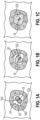
- Marker material (122) is generally expandable once disposed within a patient at a biopsy site. As shown in FIGS. 1B and 1C , the initially dehydrated marker material (122) may absorb fluid from the surrounding tissue (30) into which it is inserted. In response to this absorption of fluid, maker material (122) may swell, thereby permitting carrier (120) to fill a cavity formed at a biopsy site by removal of tissue samples during a biopsy procedure.
- Biodegradable materials may be particularly suitable in applications where it is desired that natural tissue growth be permitted to completely or partially replace the implanted material over time. Accordingly, biocompatibility is ensured, and the natural mechanical parameters of the tissue are substantially restored to those of the pre-damaged condition.
- Marker (100) may be inserted into the body either surgically via an opening in the body cavity (30), or through a minimally invasive procedure using such devices as a catheter, introducer or similar type insertion device. Marker (100) may be delivered immediately after removal of the tissue specimen using the same device used to remove the tissue specimen itself.
- Marker (100) may be delivered immediately after removal of the tissue specimen using the same device used to remove the tissue specimen itself.
- Follow-up noninvasive detection techniques such as x-ray mammography or ultrasound may then be used by the physician to identify, locate, and monitor the biopsy cavity site over a period of time via marker (100).
- Marker (100) of the present example is large enough to be readily visible to a clinician under x-ray or ultrasonic viewing, for example; yet small enough to be able to be percutaneously deployed into the biopsy cavity and to not cause any difficulties with the patient.
- aspects presented herein may be used for markers in any internal, tissue, e.g., in breast tissue, lung tissue, prostate tissue, lymph gland tissue, etc.
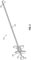
- a grip (166) can be provided at the proximal end of cannula (162).
- a push rod (168) can be provided, with push rod (168) extending coaxially in cannula (162) such that push rod (168) is configured to translate within cannula (162) to displace one or more markers through side opening (164) (see FIG. 3 ).
- Rod (168) may have sufficient rigidity in compression to push a marker from an internal lumen (165) of cannula (162) out through side opening (164) yet be relatively flexible in bending.
- a plunger (170) is coupled at the proximal end of push rod (168) for forcing push rod (168) distally in cannula (162) to deploy a marker out of cannula (162).
- a user may grasp grip (166) with two fingers and push on plunger (170) using the thumb on the same hand, so that marker delivery device (160) is operated by a user's single hand.
- a spring (not shown) or another feature may be provided about push rod (168) to bias push rod (168) proximally relative to grip (166) and cannula (162).
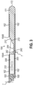
- FIG. 3 shows a cross-sectional view of a distal portion of marker delivery device (150).
- a biopsy marker (300) similar to marker (100) described above, is disposed within internal lumen (165) of cannula (162).
- marker (300) comprise a biodegradable or otherwise resorbable marker material (306), such as a generally cylindrically shaped body of collagen, hydrogel, or etc., and a metallic, generally radiopaque permanent marker or marker element (310) (shown in phantom) disposed within or otherwise carried by marker material (306).
- Cannula (162) may be formed of any suitable metallic or non-metallic material.
- cannula (162) is formed of a thin walled hollow tube formed of a suitable medical grade plastic or polymer.
- a suitable material is a thermoplastic elastomer, such as Polyether block amide (PEBA), such as is known under the tradename PEBAX ® .
- PETB Polyether block amide
- Cannula (162) may be formed of PEBAX ® and may be substantially transparent to visible light and X-ray.
- Side opening (164) may be formed by cutting away a portion of the wall of cannula (162). Side opening (164) communicates with an internal lumen (165) of cannula (162). Side opening (164) may extend axially (in a direction parallel to the axis of lumen (165)) from a proximal opening end (164A) to a distal opening end (164B), as illustrated in FIG. 3 .
- distal tip (172) extends from the distal end of cannula (162) and is rounded as shown in FIG. 3 .
- the distal end of cannula (162) is closed by a unitary endpiece (171), with a portion of endpiece (171) extending into internal lumen (165) of cannula (162).
- Endpiece (171) may be a molded or cast component.
- Endpiece (171) comprises a tip (172), a ramp (210) having a ramp surface (212), and a marker engaging element (240).
- Ramp surface (212) aids in directing marker (300) from internal lumen (165) through side opening (164).
- Marker engaging element (240) helps to retain marker (300) in internal lumen (165) until the user intends to deploy marker (300).
- Marker engaging element (240) is disposed within internal lumen (165), and at least a portion of marker engaging element (240) is disposed distally of proximal end (164A) of side opening (164). Marker engaging element (240) extends along a portion of the floor of cannula (162) under opening (164) such that marker engaging element (240) is positioned to reinforce the portion of cannula (162) in which opening (164) is formed. For instance, by positioning marker engaging element (240) underneath opening (164), as shown in FIG. 3 , element (240) helps to stiffen cannula (162) in the region where wall of cannula (162) is cut to form opening (164). As shown in FIG. 3 , marker engaging element (240) extends from the proximal most portion of ramp surface (212) and does not extend proximally of side opening (164), though in other examples, a portion of element (240) may extend proximally of opening (164).
- marker engaging element (240) is in the form of a step having a generally uniform thickness (T) along element's (240) axial length, except that element (240) has a tapered proximal end (242). Tapered proximal end (242) forms an included angle with the longitudinal axis of lumen (165) (included angle with a horizontal line in FIG. 3 ) of about 45 degrees, while ramp surface (212) forms an included angle with the longitudinal axis of about 30 degrees. Of course, any number of other suitable angles may be used.
- an upwardly facing surface (244) (surface facing opening (164)) of marker engaging element (240) extends distally to contact ramp surface (212), so that there is not a space or gap between surface (244) and ramp surface (212).
- marker engaging element (240), ramp (210), and/or tip (172) are formed of, or include, a material that is relatively more radiopaque than the wall of cannula (162).
- endpiece (171) may include a radiopaque additive, such as barium sulfate.
- endpiece (171) may be a component molded of PEBAX ® , with about 20 percent by weight barium sulfate added to the molten PEBAX ® mold composition.
- the relatively more radiopaque marker engaging element (240), ramp (210), and tip (22) may be useful in distinguishing the position of those components using radiographic imaging.
- the addition of a radiopaque material can help identify the position of opening (164), and the position of marker (300) relative to opening (164) before, during, or after deployment of marker (300).
- marker delivery device (160) is used to deploy a marker (300) to mark a biopsy location within a patient.
- a biopsy needle (400) is shown having a closed distal end with piercing tip (402) and a lateral tissue receiving aperture (414).
- Marker delivery device (160) is introduced to a biopsy site through biopsy needle (400), which may be the same needle (400) used to collect a tissue sample from the biopsy site.
- Biopsy needle (400) may be of the type used with single insertion, multiple sample vacuum assisted biopsy devices. Several such biopsy devices are disclosed in the various patents and patent applications that have been referred to herein, though other biopsy devices may be used.
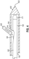
- FIG. 4 shows the distal end of marker delivery device (160) disposed within needle (400).
- Needle (400) may be positioned in tissue, and a biopsy sample may be obtained through lateral aperture (414), thereby providing a biopsy cavity adjacent lateral aperture (414). Then, after the tissue sample has been obtained and transferred proximally through needle (400), and without removing needle (400) from the patient's tissue, marker delivery device (160) is inserted into a proximal opening in needle (400).
- needle (400) and marker delivery device (160) are positioned such that opening (164) of cannula (162) and lateral aperture (414) of needle (400) are substantially aligned axially and circumferentially.
- push rod (168) is advanced to deploy marker (300) up ramp surface (212), through opening (164), and then through lateral aperture (414), into the biopsy cavity.
- FIG. 5 shows a biopsy device (340) including a holster (320), a probe (330), and a tissue sample holder (380).
- Holster (320) of the present example includes various internal components configured to drive various functions of biopsy device (340).
- holster (320) may include a motor (not shown), a rotating member (not shown), and one or more holster gears (not shown).
- the motor may be in communication with the rotating member to drive movement of various components via the rotating member such as one or more holster gears.
- Holster (320) is operatively connected to probe (330) and tissue sample holder (380) is operatively connected to the proximal end of probe (330).
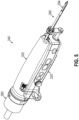
- FIG. 6 shows probe (330) of biopsy device (340) in greater detail.
- Probe (320) includes a needle (400), a lateral aperture (414), a manifold ring (318), a proximal face (316), and a pair of pins (314).
- probe (320) also includes an accessory gear (352), an accessory shaft (350) (also may be referred to as a shaft adaptor), a gripping member (312), and a manifold shaft (334).
- Accessory gear (352) is operatively connected to the distal end of accessory shaft (350) and the gripping member (312) is operatively connected to the proximal end of accessory shaft (350).
- Accessory gear (352) is in communication with the one or more holster gears of holster (320), as described above.
- Tissue sample holder (380) of the present example is generally configured to collect one or more tissue samples therein.
- tissue sample holder (380) can include a rotatable member having a plurality of chambers. Such a rotatable member may be configured to receive a tissue sample tray within each chamber of the plurality of chambers. The rotatable member may then be rotated sequentially to collect one or more tissue samples within each tissue sample tray.
- tissue sample holder (380) can be configured in accordance with at least some of the teachings of US Pub. No. 2018/0221002, entitled “Biopsy System," published August 9, 2018 .
- Tissue sample holder (380) includes a coupler (378) configured to couple at least a portion of tissue sample holder (380) to probe (320).
- Coupler (378) includes an annular ring (332) and a latching feature (336).
- latching feature (336) may be configured to receive one or more components of probe (320) to couple tissue sample holder (380) to probe (320) similar to a bayonet fitting or other mechanical fastener.
- tissue sample holder (380) can be configured to rotate to facilitate collection of one or more tissue samples within a plurality of chambers of tissue sample holder (380).
- tissue sample holder (380) includes manifold shaft (334), which is configured to engage one or more components of probe (320) to thereby communicate rotary motion from probe (320) to tissue sample holder (380).
- some marker delivery devices can be equipped with an elongate cannula that can be configured for insertion into needle (390, 400). This configuration can present challenges with manipulation of the marker delivery device due to the flexibility of the cannula and the diameter relative to the axial length.
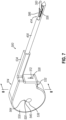
- FIGS. 7-8 show an exemplary marker delivery device (500) that is generally configured to deploy marker (300) through a lateral aperture of a biopsy needle. It should be understood that marker delivery device (500) substantially similar to marker delivery device (150) (see FIG. 2 ) unless otherwise described herein. Like marker delivery device (150) described above, at least a portion of marker delivery device (500) is insertable into needle (400) or needle (390) to deploy marker (300) through lateral aperture (414). Additionally, marker deliver device (150) includes a housing (514) configured to be gripped by the operator similar to grip (166) described above.
- FIG. 7 shows housing (514) of marker delivery device (500) in detail.
- housing (514) includes an annular portion (530), a rectangular portion (532), and an elongate portion (534).
- Rectangular portion (532) extends distally from annular portion (530) to elongate portion (534).
- Rectangular portion (532) is substantially rectangular in shape and is generally configured to be gripped by an operator.
- Rectangular portion (532) can be any suitable shape.
- rectangular portion (532) may be arcuate, or triangular.
- rectangular portion (532) may extend from annular portion (530) to form a pistol grip
- Elongate portion (534) extends distally from rectangular portion (532).
- a distal end of elongate portion (534) may be configured to abut a proximal end of needle (400) as shown in FIG. 7 .
- elongate portion (534) may be further configured for insertion into one or more components of a biopsy device.
- elongate portion (534) may be configured for insertion into tissue sample holder (380) for deployment of marker (300) through needle (390).
- elongate portion (534) is generally tubular in shape.
- elongate portion (534) is shown as having a generally square tubular shape, it should be understood that a variety of other suitable shapes may be used such as an elongate cross-section that is rectangular, triangular, or oval-like in shape.
- housing (514) may include a coupler or other structures configured to couple marker delivery device (500) to structures associated with needle (400) such as a housing of a probe similar to probe (330) described above.
- such couplers may include an annular ring, latching features, or other similar features configured to engage one or more corresponding structures associated with needle (400). Suitable couplers that may be readily incorporated into housing (514) are described in greater detail below in connection with marker delivery device (600).
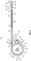
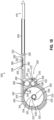
- housing (514) includes a flexible push rod (516), a rack stowage drum (518), a spring (520), an idler gear (566), a rack drive gear (568), a deployer tip (526), and a release mechanism (528).
- annular portion (530) defines an interior surface (536), a drum aperture (538), and a spring retainer aperture (540).
- Interior surface (536), drum aperture (538), and spring retainer aperture (540) are together configured to contain and/or hold at least a portion of flexible push rod (516), rack stowage drum (518), spring (520), idler gear (566), rack drive gear (568), deployer tip (526), and release mechanism (528), as will be described in greater detail below.
- Flexible push rod (516) includes a smooth side (542) and a rack teeth side (544). Smooth side (542) is configured to slidably engage the interior of housing (514) and/or needle (400). Thus, it should be understood that smooth side (542) is generally configured to reduce friction between interior surfaces of housing (514) and/or needle (400) and flexible push rod (516). To further reduce friction, in some examples, flexible push rod (516) may be additionally lubricated with a sterile grease or oil. In addition, or in the alternative, flexible push rod (516) may be lubricated with saline or any other suitable medical fluid known in the art to have lubricating properties.
- Rack teeth side (544) includes a transverse drive surface in the form of a set of rack teeth (546).
- rack teeth (546) are generally configured to mate with at least a portion of rack stowage drum (518) to drive movement of flexible push rod (516).
- rack teeth (546) in the present example are shown and described as teeth, it should be understood that other suitable transverse drive surfaces may be used.
- rack teeth (546) may alternatively be configured as cogs, or arcuate beads, and/or etc.
- flexible push rod (516) may be referred to as a flexible rack, a flexible beaded rod, a flexible deployment rod, and/or etc.
- Spring (520) is positioned within housing (514) proximate rack stowage drum (518) such that spring is generally configured to drive rotation of rack stowage drum (518).
- Spring (520) may thus comprise a variety of resilient materials such as metal, plastic, and/or etc.
- Spring (520) is configured to move between a biased state and a relaxed state.
- Spring has a helical portion (560), first spring end (562), and a second spring end (564).
- Helical portion (560) is wound around drum shaft (554).
- drum shaft (554) may be hollow and helical portion (560) may be inside drum shaft (554).
- rack drive gear (568) includes a plurality of teeth (569) oriented around an outer circular perimeter thereof.
- Rack drive gear (568) is also disposed within housing (514) proximate idler gear (566) such that teeth (569) are configured to engage idler teeth (598).
- Rack drive gear (568) is additionally positioned proximate flexible push rod (516) such that teeth (569) of rack drive gear (568) are configured to engage and support at least a portion of flexible push rod (516) via rack teeth (546).
- rack drive gear (568) is configured to keep flexible push rod (516) from being displaced downwardly in relation to a top of rectangular portion (532).
- rack gear (568) may also be referred to as a wheel, a gear, a support, and/or etc.
- Button (572) is configured to be actuated by an operator to begin the deployment sequence.
- button (572) engages arm (576).
- Arm (576) is configured to move about pivot point (578) when button (572) engages arm (576).
- Dog (574) is configured to hold idler gear (566) stationary with spring (520) under tension in the biased state and rack storage drum (518) in the wound state.
- dog (574) may be removably coupled to rack drive gear (568) or stowage drum (518). Any other release mechanism (528) known in the art may be utilized that may removably couple to a gear.
- marker delivery device (500) is initially inserted into needle (400). As can be seen in FIG. 10 , marker delivery device (500) is initially in the wound state when inserted into needle (400). In the wound state, flexible push rod (516) is retracted into a proximal position such that elongate portion (534) houses a portion of flexible push rod (516), marker (300) and deployer tip (526). Spring (520) is biased in the wound state. Flexible push rod (516) is substantially wound around rack stowage drum (518) with a portion of flexible push rod (516) extending distally from rack stowage drum (518) through a top of rectangular portion (532) and further extending through elongate portion (534).
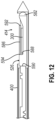
- FIG. 12 shows a distal portion of biopsy needle (400) with deployer tip (526) fully deployed.
- deployer tip (526) has translated through biopsy needle (400).
- distal tip (582) of deployer tip (526) engages a proximal face the interior of needle (400).
- flexible push rod (516) and deployer tip (526) translate together in the same direction within needle (400).
- distal tip (582) of deployer tip (526) contacts a proximal face needle (400)
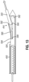
- further translation of deployer tip (526) is prevented such that flexible push rod (516) may continue to translate within deployer tip (526), and relative to deployer tip (526).
- spring (520) may continue to rotate rack stowage drum (518) in a clockwise direction while drum gear teeth (548) engage rack teeth (546), and flexible push rod (516) translates distally.
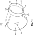
- FIG. 14-15 shows another exemplary coiled rack marker delivery device (600) configured to couple to biopsy device (340) described above.
- FIG. 14 shows marker delivery device (600) in isolation; while FIG. 15 shows the marker delivery device (600) coupled to the proximal end of biopsy device (340).
- Marker delivery device (600) is substantially similar to marker delivery device (500) discussed above.
- marker delivery device (600) likewise includes structures substantially similar to flexible push rod (516), deployer tip (526), spring (520), rack stowage drum (518), idler gear (566), a rack drive gear (568), and release mechanism (528) described above.
- marker delivery device (600) can be used to deploy a marker using a procedure similar to the deployment procedure described above with respect to marker delivery device (500).
- release mechanism (670) may be actuated to release internal structures and/or components similar to rack stowage drum (518). As similarly discussed above, such internal structures and/or components may be biased by spring (620) such that release via release mechanism (670) may result in movement of such structures and/or components.
- release mechanism (670) is actuated, structures similar to flexible push rod (516) may be driven by internal components, resulting in such structures being driven distally through an aperture or opening in distal face (684). Such structures similar to flexible push rod (516) may then translates through biopsy device (340) and into needle (390) for deployment of marker (300).
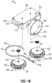
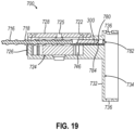
- Marker delivery device (700) may be thus coupled to proximal end of probe (320) in similar fashion as marker delivery device (600) and/or tissue sample holder (380) described above.
- latching features (736) may be aligned with pins (314) on manifold ring (318).
- Annular ring (732) is moved longitudinally over manifold ring (318) until distal face (734) engages proximal face (316) of probe (330).
- Marker delivery device (700) may then be rotated to a locked position. In the locked position, latching features (736) engage pins (314) and retain the marker delivery device (700) in a bayonet mount fashion
- This meshing relationship between gear teeth (746) permits one gear (724) to drive another.
- this meshing relationship can be used to maintain synchronized rotation between gears (724).
- this meshing relationship can be used such that only a single spring (720) can be used to rotate one gear (724), while the other gear (724) is rotated by rotation of the gear (724) associated with the single spring (720).
- gear teeth (746) can mesh with a drive train or other components so that springs (720) can be omitted entirely with gears (724) being rotated by an external power source (e.g., gripping member (312) of biopsy device (340)).
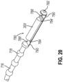
- flexible push rod (716) includes a drive portion defined by a plurality of beads (718).
- flexible push rod (716) may be referred to as a flexible beaded rod in some examples.
- Beads (718) are generally configured to provide an irregular drive surface, which can be engaged by beaded drive surface (787) to move flexible push rod (716).
- Each bead (718) comprises a protrusion having a generally spherical shape.
- each bead (718) can have a variety of alternative shapes such as oval-shaped, square-shaped, rectangular-shaped, elliptical-shaped, and/or etc.
- each bead (718) is shown as a protrusion in the present example, it should be understood that in other examples, the configuration of each bead (718) can be readily reversed and instead be an indentation.
- Beads (718) are arranged along a length of flexible push rod (716) at equal intervals. Corresponding indentations in beaded drive surface (787) likewise are spaced at equal intervals corresponding to the spacing used in flexible push rod (716). With such correspondence, flexible push rod (716) may be received between gears (724) and each beaded drive surface (787) may engage one or more beads (718). Rotation of gears (724) may then drive beads (718), and thus flexible push rod (716), in the direction of rotation of gears (724). As gears (724) rotate, additional beads (718) may become engaged by beaded drive surface (787), while other beads (718) become disengaged. Thus, beaded drive surface (787) and beads (718) are configured to operate similarly to gear teeth in meshing gears.
- Flat upper portion (788) and arcuate bottom portion (790) are configured to transition living hinge (784) from the unflexed position to the flexed position. As can be seen, living hinges (784), flat upper portion (788) and arcuate bottom portion (790) all lay flat when in the unflexed position.
- a distal tip (782) of deployer tip (780) may contact a distal structure of a needle similar to needle (400). This contact may prevent movement of distal tip (782), while flexible push rod (716) continues to move distally, accumulating tension within flexible push rod (716). Once a sufficient amount of tension is accumulated, living hinges (784) will buckle and push flat upper portion (788) and arcuate bottom portion (790) upwardly to deploy marker (300).
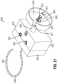
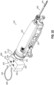
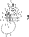
- FIGS. 21-23 show another marker delivery device (800) that is configured to be coupled to a proximal end of a biopsy device (340) in lieu of tissue sample holder (380).
- FIG. 21 shows marker delivery device (800) in isolation; while FIG. 22 shows marker delivery device (800) coupled to biopsy device (340) in lieu of tissue sample holder (380).
- biopsy device (340) is configured to drive rotation of one or more components of tissue sample holder (380) via gripping member (312).
- marker delivery device (800) of the present example is generally configured to use such functionality to drive portions thereof.
- Marker delivery device (800) is substantially similar to marker delivery device (700) described above.
- marker delivery device (800) includes a housing (814) having a proximal housing portion (830), a distal housing portion (832), and an elongate portion (834).
- Housing (814) is constructed of any suitable rigid material known in the art such as plastic, aluminum, or stainless steel.
- Proximal housing portion (830) and distal housing portion (832) are fitted together with any suitable fastener such as rivets, screws, or bolts.
- Proximal housing portion (830) and distal housing portion (832) may also be fused with welding.
- Distal housing portion (832) is operatively fixed to elongate portion (834) that extends distally from distal housing portion (832).
- Drive shaft assembly (840) includes a third bearing (819), a drive gear (849), a drive bevel gear (852), a drive shaft (854), a fourth bearing (820), and a shaft collar (856).
- Drive shaft assembly (840) is arranged transverse to longitudinal shaft assembly (836).
- Third bearing (819) is disposed between top of proximal housing portion (830) and top of distal housing portion (832).
- Drive shaft (854) is axially fixed, but remains rotatable via third bearing (819).
- Drive gear (849) is affixed to drive shaft (854), below third bearing (819).
- Drive bevel gear (852) is affixed to drive shaft (854) below drive gear (849).
- drive bevel gear (852) may be disposed within drive gear (849).
- Fourth bearing (820) is disposed between bottom of proximal housing portion (830) and bottom of distal housing portion (832).
- Drive shaft extends distally through bottom of housing (814).
- Shaft collar (856) is affixed to a portion of drive shaft (854) that extends from bottom of housing (814).
- Longitudinal shaft adapter (812) protrudes through longitudinal aperture (828) disposed in distal face (see FIG. 21 ).
- Longitudinal shaft adapter (812) is configured to be rotatably coupled to gripping member (312).
- longitudinal shaft adapter (812) includes a coupler (882) and a mating shaft (884). Coupler (882) is configured to be affixed to distal end of longitudinal shaft (844).
- Mating shaft (884) has a generally arcuate shape.
- Mating shaft (884) is configured to be mated with gripping member (312) of biopsy probe (320).
- mating shaft (884) of the present example includes a keyed configuration. Although a particular keyed configuration for mating shaft (884) is shown, it should be understood that in other examples various alterative configurations may be used such as square-shaped, triangular-shaped, hex-shaped, and/or etc.
- Gripping member (312) couples to longitudinal shaft adapter (812), similar to how gripping member (312) couples to manifold shaft (334) to rotate tissue sample holder (380). Further discussion of how gripping member (312) is rotated by a motor (not shown) is discussed above.
- gripping member (312) rotates longitudinal shaft adapter (812).
- Longitudinal shaft adapter (836) rotates longitudinal shaft (844).
- Longitudinal shaft (844) rotates longitudinal bevel gear (846).
- Longitudinal bevel gear (846) engages drive bevel gear (852) and rotates drive bevel gear (852).
- Drive bevel gear (852) rotates drive shaft (854) and drive gear (849).
- Drive shaft (854) rotates drive gear (849).
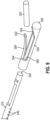
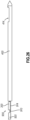
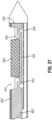
- FIG. 25 shows a deployer tip (900) extending distally from a flexible push rod (920).
- Deployer tip (900) can be used with any of above marker delivery devices (500, 600, 700, 800).
- push rod (920) of the present example may be readily substituted with any one or more of push rods (516, 716, 816).
- deployer tip (900) is shown herein as being generally integral with flexible push rod (920), it should be understood that in other examples, deployer tip (900) and flexible push rod (920) may be separate components coupled together by any suitable means.
- Flat portion (914) is configured to provide a generally flat section for a marker such as marker (300) to rest upon.
- flat portion is configured to hold marker (300) or other markers.
- flat portion (914) of the present example is shown as being used with marker (300), it should be understood that various alternative markers may be readily used with flat portion (914).
- flat portion (914) may include one or more locating features to hold marker (300) in a specific position on flat portion (914) until deployment occurs.
- suitable locating features may include steps, detents, rounds, ribs, and/or etc.
- Each living hinge (910) has an unflexed position and a flexed position.
- living hinge (910) is shown in the unflexed position.
- deployer tip (900) may be configured for insertion into a component such as needle (400).
- flexible push rod (920) may used for insertion of deployer tip (900) within a proximal end of needle (400) of biopsy device (340) while each living hinge (910) is in the unflexed position.
Landscapes
- Health & Medical Sciences (AREA)
- Life Sciences & Earth Sciences (AREA)
- Surgery (AREA)
- Biomedical Technology (AREA)
- General Health & Medical Sciences (AREA)
- Heart & Thoracic Surgery (AREA)
- Medical Informatics (AREA)
- Molecular Biology (AREA)
- Pathology (AREA)
- Animal Behavior & Ethology (AREA)
- Engineering & Computer Science (AREA)
- Public Health (AREA)
- Veterinary Medicine (AREA)
- Nuclear Medicine, Radiotherapy & Molecular Imaging (AREA)
- Oral & Maxillofacial Surgery (AREA)
- Oncology (AREA)
- Surgical Instruments (AREA)
- Infusion, Injection, And Reservoir Apparatuses (AREA)
Claims (15)
- Markerfreisetzungsvorrichtung, umfassend:(a) ein Gehäuse (514);(b) eine flexible Schubstange (516), wobei die Schubstange (516) eine erste querverlaufende Antriebsoberfläche und eine Einsatzspitze (526) einschließt, wobei die Einsatzspitze (526) so konfiguriert ist, dass sie einen Biopsiestellenmarker (300) aufnimmt; und(c) ein erstes Rad (518), das eine zweite querverlaufende Antriebsoberfläche aufweist, wobei die erste querverlaufende Antriebsoberfläche so konfiguriert ist, dass sie von der zweiten querverlaufenden Antriebsoberfläche angetrieben wird, um die Schubstange distal zu verschieben;(d) eine erste Welle (554) und eine Feder (520), wobei die erste Welle (554) so konfiguriert ist, dass sie das erste Rad (518) drehbar mit dem Gehäuse (514) koppelt;
dadurch gekennzeichnet, dass(e) ein Antrieb die erste Welle (554) und die Feder (520) einschließt, die Feder (520) ein erstes Ende und ein zweites Ende einschließt, das erste Ende mit der ersten Welle (554) gekoppelt ist und das zweite Ende mit dem ersten Rad (518) gekoppelt ist, wobei die Feder (520) zwischen einer ersten Position und einer zweiten Position vorgespannt ist, wobei die Feder (520) in der zweiten Position so konfiguriert ist, dass sie das erste
Rad (518) dreht und die Schubstange (516) in einer koordinierten linearen und rotierenden Bewegung relativ zum Gehäuse (514) verschiebt, um den Marker (300) einzusetzen; und(f) einen Freigabemechanismus (528), wobei der Freigabemechanismus (528) dazu konfiguriert ist, die Feder (520) in der ersten Position zu halten und die Einsatzsequenz bei Betätigung durch einen Bediener zu starten. - Markerfreisetzungsvorrichtung nach Anspruch 1, wobei die erste Position eine vorgespannte Position ist und die zweite Position eine entspannte Position ist, wobei die Feder (520) in der vorgespannten Position so konfiguriert ist, dass sie unter Spannung steht.
- Markerfreisetzungsvorrichtung nach Anspruch 2, weiter umfassend ein zweites Rad (568), das eine dritte querverlaufenden Antriebsoberfläche aufweist, wobei die dritte querverlaufende Antriebsoberfläche dazu konfiguriert ist, mit der ersten querverlaufenden Antriebsoberfläche in Eingriff zu treten, um die flexible Schubstange (516) in der Querrichtung relativ zu der flexiblen Schubstange (516) zu stützen.
- Markerfreisetzungsvorrichtung nach Anspruch 3, weiter umfassend ein drittes Rad (566), das eine vierte querverlaufende Antriebsoberfläche aufweist, wobei die vierte querverlaufende Antriebsoberfläche so konfiguriert ist, dass sie mit der dritten querverlaufenden Antriebsoberfläche in Eingriff steht, um das zweite Rad (568) stationär zu halten, während sich die Feder (520) in der vorgespannten Position befindet.
- Markerfreisetzungsvorrichtung nach Anspruch 2 oder 3, wobei der Freigabemechanismus (528) so konfiguriert ist, dass er lösbar mit der ersten querverlaufenden Antriebsoberfläche gekoppelt ist, wobei der Freigabemechanismus (528) weiter so konfiguriert ist, dass er die Feder (520) in der vorgespannten Position hält und die Spannung in der Feder (520) löst, um dadurch die Feder von der vorgespannten Position in die entspannte Position zu überführen.
- Markerfreisetzungsvorrichtung nach Anspruch 2 oder 3, wobei der Freigabemechanismus so konfiguriert ist, dass er lösbar mit der zweiten querverlaufenden Antriebsoberfläche gekoppelt ist, wobei der Freigabemechanismus (528) weiter so konfiguriert ist, dass er die Feder (520) in der vorgespannten Position hält und die Spannung in der Feder (520) löst, um dadurch die Feder (520) von der vorgespannten Position in die entspannte Position zu überführen.
- Markerfreisetzungsvorrichtung nach Anspruch 3, wobei der Freigabemechanismus (528) so konfiguriert ist, dass er lösbar mit der dritten querverlaufenden Antriebsoberfläche gekoppelt ist, wobei der Freigabemechanismus (528) weiter so konfiguriert ist, dass er die Feder (520) in der vorgespannten Position hält und die Spannung in der Feder (520) löst, um dadurch die Feder (520) von der vorgespannten Position in die entspannte Position zu überführen.
- Markerfreisetzungsvorrichtung nach Anspruch 4, , wobei der Freigabemechanismus (528) so konfiguriert ist, dass er lösbar mit der vierten Antriebsoberfläche gekoppelt ist, wobei der Freigabemechanismus (528) weiter so konfiguriert ist, dass er die Feder (520) in der vorgespannten Position hält und die Spannung in der Feder (520) löst, um dadurch die Feder (520) von der vorgespannten Position in die entspannte Position zu überführen.
- Markerfreisetzungsvorrichtung nach einem oder mehreren der Ansprüche 1 bis 8, wobei die Einsatzspitze (526) eine Klappe (586) einschließt, die ein freies Ende (592) und ein gelenkiges Ende (594) aufweist, wobei die Klappe (586) so konfiguriert ist, dass sie zwischen einem offenen Zustand und einem geschlossenen Zustand übergeht, wobei das gelenkige Ende (594) so konfiguriert ist, dass es durch eine innere Oberfläche einer Biopsienadel (400) im geschlossenen Zustand gehalten wird, wobei das freie Ende (592) weiter so konfiguriert ist, dass es sich auf einem bogenförmigen Weg dreht, um die Klappe (586) in den offenen Zustand zu überführen, wenn sie nicht durch die innere Oberfläche der Biopsienadel (400) geschlossen gehalten wird,
wobei die Einsatzspitze (526) weiter eine distale Spitze (582), eine Rampe (584) und eine Aussparung (588) einschließt, wobei die distale Spitze (526) so konfiguriert ist, dass sie in eine proximale Fläche der Biopsienadel (400) eingreift, wobei die Rampe (584) so konfiguriert ist, dass sie quer in den Marker (300) eingreift und den Marker (300) in eine Querrichtung relativ zur Biopsienadel (400) verschiebt, wenn die distale Spitze (526) mit der proximalen Fläche der Biopsienadel (400) in Eingriff gelangt, wobei die Aussparung (588) verschiebbar mit der Schubstange (516) gekoppelt ist, wobei die Aussparung (588) so konfiguriert ist, dass sich die flexible Schubstange (516) durch die Aussparung (588) bewegen kann, um mit dem Marker (300) in Eingriff zu treten und den Marker (300) entlang der Rampe (584) zu verschieben. - Markerfreisetzungsvorrichtung nach einem oder mehreren der Ansprüche 1 bis 9, wobei die Einsatzspitze (526) ein erstes bewegliches Scharnier (784, 910), einen flachen Abschnitt (788, 914), und eine distale Spitze (582) einschließt, wobei das erste bewegliche Scharnier (784, 910) ein elastisches Material einschließt und eine Vielzahl von bogenförmigen Halbbohrungen (918) definiert, wobei das erste bewegliche Scharnier (784, 910) so konfiguriert ist, dass es zwischen einer Ruheposition und einer gebeugten Position übergeht, wobei der flache Abschnitt (788, 914) proximal des ersten beweglichen Scharniers (784, 910) angeordnet ist und so konfiguriert ist, dass er den Marker (300) hält, wobei die distale Spitze (526) so konfiguriert ist, dass sie in eine proximale Fläche einer Biopsienadel (400) eingreift, um dadurch das erste bewegliche Scharnier (784, 910) von der Ruheposition in die gebeugte Position zu überführen.
- Markerfreisetzungsvorrichtung nach Anspruch 10, wobei die Einsatzspitze (526) weiter ein zweites bewegliches Scharnier (784, 910) einschließt, wobei das erste bewegliche Scharnier (784, 910) relativ zum flachen Abschnitt (788, 914) proximal angeordnet ist, das zweite bewegliche Scharnier (784, 910) relativ zum flachen Abschnitt (788, 914) distal angeordnet ist, wobei das zweite bewegliche Scharnier (784, 910) weiter relativ zur distalen Spitze (526) proximal angeordnet ist.
- Markerfreisetzungsvorrichtung nach einem oder mehreren der Ansprüche 1 bis 11, wobei die Schubstange (516) eine glatte Seite (542) einschließt, wobei die glatte Seite (542) so konfiguriert ist, dass sie gleitend in eine innere Oberfläche einer Biopsienadel (400) eingreift.
- Markerfreisetzungsvorrichtung nach einem oder mehreren der Ansprüche 8 bis 12, wobei die erste querverlaufende Antriebsoberfläche, die zweite querverlaufende Antriebsoberfläche, die dritte querverlaufende Antriebsoberfläche und die vierte querverlaufende Antriebsoberfläche alle eine Vielzahl von Verzahnungen einschließen.
- Markerfreisetzungsvorrichtung nach Anspruch 4 oder 8, wobei die erste querverlaufende Antriebsoberfläche, die zweite querverlaufende Antriebsoberfläche, die dritte querverlaufende Antriebsoberfläche und die vierte querverlaufende Antriebsoberfläche alle einen gebördelten Abschnitt einschließen.
- Markerfreisetzungsvorrichtung nach einem oder mehreren der Ansprüche 1 bis 14, weiter umfassend ein steriles Schmiermittel, das innerhalb des Gehäuses angeordnet ist, wobei das sterile Schmiermittel dazu konfiguriert ist, eine Reibung zwischen einer inneren Oberfläche des Gehäuses und zumindest einem Abschnitt der Schubstange (516) zu verringern.
Applications Claiming Priority (2)
| Application Number | Priority Date | Filing Date | Title |
|---|---|---|---|
| US202062961367P | 2020-01-15 | 2020-01-15 | |
| PCT/US2021/013352 WO2021146367A2 (en) | 2020-01-15 | 2021-01-14 | Marker delivery device with push rod having actuation features |
Publications (2)
| Publication Number | Publication Date |
|---|---|
| EP4072462A2 EP4072462A2 (de) | 2022-10-19 |
| EP4072462B1 true EP4072462B1 (de) | 2025-04-09 |
Family
ID=74798009
Family Applications (1)
| Application Number | Title | Priority Date | Filing Date |
|---|---|---|---|
| EP21708782.4A Active EP4072462B1 (de) | 2020-01-15 | 2021-01-14 | Markerfreisetzungsvorrichtung mit schubstange mit betätigungsfunktion |
Country Status (4)
| Country | Link |
|---|---|
| US (1) | US12402978B2 (de) |
| EP (1) | EP4072462B1 (de) |
| CN (1) | CN115135276A (de) |
| WO (1) | WO2021146367A2 (de) |
Families Citing this family (2)
| Publication number | Priority date | Publication date | Assignee | Title |
|---|---|---|---|---|
| EP4436487A1 (de) * | 2021-11-24 | 2024-10-02 | Bard Peripheral Vascular, Inc. | Vakuumunterstützte biopsievorrichtung mit ventilgesteuerter entlüftung und integrierter markerausgabe |
| CN118121329A (zh) * | 2024-04-15 | 2024-06-04 | 首都医科大学宣武医院 | 一种医用串珠式定位标记装置 |
Citations (1)
| Publication number | Priority date | Publication date | Assignee | Title |
|---|---|---|---|---|
| EP1836979B1 (de) * | 2006-03-21 | 2012-05-23 | Ethicon Endo-Surgery, Inc. | Medizinisches Instrument mit Kupplungsmechanismus |
Family Cites Families (15)
| Publication number | Priority date | Publication date | Assignee | Title |
|---|---|---|---|---|
| US2883984A (en) * | 1957-09-09 | 1959-04-28 | Pfizer & Co C | Pellet implanter |
| ZA978537B (en) | 1996-09-23 | 1998-05-12 | Focal Inc | Polymerizable biodegradable polymers including carbonate or dioxanone linkages. |
| US6162241A (en) | 1997-08-06 | 2000-12-19 | Focal, Inc. | Hemostatic tissue sealants |
| US6270464B1 (en) | 1998-06-22 | 2001-08-07 | Artemis Medical, Inc. | Biopsy localization method and device |
| US6605294B2 (en) | 1998-08-14 | 2003-08-12 | Incept Llc | Methods of using in situ hydration of hydrogel articles for sealing or augmentation of tissue or vessels |
| US6356782B1 (en) | 1998-12-24 | 2002-03-12 | Vivant Medical, Inc. | Subcutaneous cavity marking device and method |
| US7761137B2 (en) * | 2005-12-16 | 2010-07-20 | Suros Surgical Systems, Inc. | Biopsy site marker deployment device |
| US8939910B2 (en) | 2006-03-28 | 2015-01-27 | Devicor Medical Products, Inc. | Method for enhancing ultrasound visibility of hyperechoic materials |
| US20140039343A1 (en) | 2006-12-13 | 2014-02-06 | Devicor Medical Products, Inc. | Biopsy system |
| WO2012010783A1 (fr) * | 2010-07-19 | 2012-01-26 | INSERM (Institut National de la Santé et de la Recherche Médicale) | Outil d'insertion d'objets tubulaires fins dans la cochlée |
| US9370448B2 (en) * | 2012-06-15 | 2016-06-21 | Preceptis Medical, Inc. | Insertion system for deploying a ventilation device |
| EP2719355A3 (de) * | 2012-10-11 | 2014-05-21 | Cook Medical Technologies LLC | Handstück mit gekuppeltem Zahnstangenrad für das Einsetzen von Markern |
| CN105007864B (zh) * | 2013-01-18 | 2017-03-22 | 标枪医疗有限公司 | 单丝植入物和用于递送单丝植入物的系统 |
| US9592110B1 (en) * | 2013-12-06 | 2017-03-14 | Javelin Medical, Ltd. | Systems and methods for implant delivery |
| US9999758B2 (en) * | 2014-09-19 | 2018-06-19 | Transmed7, Llc | In-situ material delivery devices and methods |
-
2021
- 2021-01-14 EP EP21708782.4A patent/EP4072462B1/de active Active
- 2021-01-14 CN CN202180014914.1A patent/CN115135276A/zh active Pending
- 2021-01-14 WO PCT/US2021/013352 patent/WO2021146367A2/en not_active Ceased
-
2022
- 2022-07-13 US US17/863,813 patent/US12402978B2/en active Active
Patent Citations (1)
| Publication number | Priority date | Publication date | Assignee | Title |
|---|---|---|---|---|
| EP1836979B1 (de) * | 2006-03-21 | 2012-05-23 | Ethicon Endo-Surgery, Inc. | Medizinisches Instrument mit Kupplungsmechanismus |
Also Published As
| Publication number | Publication date |
|---|---|
| EP4072462A2 (de) | 2022-10-19 |
| WO2021146367A3 (en) | 2021-08-26 |
| US20220346907A1 (en) | 2022-11-03 |
| US12402978B2 (en) | 2025-09-02 |
| WO2021146367A2 (en) | 2021-07-22 |
| CN115135276A (zh) | 2022-09-30 |
Similar Documents
| Publication | Publication Date | Title |
|---|---|---|
| CN102355860B (zh) | 具有分离的组织室的活检装置 | |
| EP2092893B1 (de) | Biopsiestellen-Markierungsaufbringer | |
| CN113873964B (zh) | 用于直接标记的方法和设备 | |
| WO2007021904A2 (en) | Single-insertion, multiple sampling biopsy device usable with various transport systems and integrated markers | |
| US12402978B2 (en) | Marker delivery device with push rod having actuation features | |
| EP3866700B1 (de) | Biopsiesystem mit endeinsatznadel | |
| CN109982650A (zh) | 用于在单次插入中收集多个样本的芯针活检装置 | |
| US20220071608A1 (en) | Shape memory marker deployment device | |
| CN113301867B (zh) | 具有无菌导引件的标记物递送装置 | |
| US20250235290A1 (en) | Biopsy device with end deployment for marker delivery | |
| EP4231957B1 (de) | Markerfreisetzungsvorrichtung zur entkopplung von kolben und schubstange | |
| US20240225779A9 (en) | Fluid deployment mechanism for biopsy site marker | |
| AU2015255262A1 (en) | Biopsy device with discrete tissue chambers |
Legal Events
| Date | Code | Title | Description |
|---|---|---|---|
| STAA | Information on the status of an ep patent application or granted ep patent |
Free format text: STATUS: UNKNOWN |
|
| STAA | Information on the status of an ep patent application or granted ep patent |
Free format text: STATUS: THE INTERNATIONAL PUBLICATION HAS BEEN MADE |
|
| PUAI | Public reference made under article 153(3) epc to a published international application that has entered the european phase |
Free format text: ORIGINAL CODE: 0009012 |
|
| STAA | Information on the status of an ep patent application or granted ep patent |
Free format text: STATUS: REQUEST FOR EXAMINATION WAS MADE |
|
| 17P | Request for examination filed |
Effective date: 20220715 |
|
| AK | Designated contracting states |
Kind code of ref document: A2 Designated state(s): AL AT BE BG CH CY CZ DE DK EE ES FI FR GB GR HR HU IE IS IT LI LT LU LV MC MK MT NL NO PL PT RO RS SE SI SK SM TR |
|
| DAV | Request for validation of the european patent (deleted) | ||
| DAX | Request for extension of the european patent (deleted) | ||
| GRAP | Despatch of communication of intention to grant a patent |
Free format text: ORIGINAL CODE: EPIDOSNIGR1 |
|
| STAA | Information on the status of an ep patent application or granted ep patent |
Free format text: STATUS: GRANT OF PATENT IS INTENDED |
|
| RIC1 | Information provided on ipc code assigned before grant |
Ipc: A61B 10/00 20060101ALI20241128BHEP Ipc: A61B 10/02 20060101ALI20241128BHEP Ipc: A61B 90/00 20160101AFI20241128BHEP |
|
| INTG | Intention to grant announced |
Effective date: 20241210 |
|
| P01 | Opt-out of the competence of the unified patent court (upc) registered |
Free format text: CASE NUMBER: APP_428/2025 Effective date: 20250106 |
|
| GRAS | Grant fee paid |
Free format text: ORIGINAL CODE: EPIDOSNIGR3 |
|
| GRAA | (expected) grant |
Free format text: ORIGINAL CODE: 0009210 |
|
| STAA | Information on the status of an ep patent application or granted ep patent |
Free format text: STATUS: THE PATENT HAS BEEN GRANTED |
|
| AK | Designated contracting states |
Kind code of ref document: B1 Designated state(s): AL AT BE BG CH CY CZ DE DK EE ES FI FR GB GR HR HU IE IS IT LI LT LU LV MC MK MT NL NO PL PT RO RS SE SI SK SM TR |
|
| REG | Reference to a national code |
Ref country code: GB Ref legal event code: FG4D |
|
| REG | Reference to a national code |
Ref country code: CH Ref legal event code: EP |
|
| REG | Reference to a national code |
Ref country code: DE Ref legal event code: R096 Ref document number: 602021028873 Country of ref document: DE |
|
| REG | Reference to a national code |
Ref country code: IE Ref legal event code: FG4D |
|
| REG | Reference to a national code |
Ref country code: NL Ref legal event code: MP Effective date: 20250409 |
|
| PG25 | Lapsed in a contracting state [announced via postgrant information from national office to epo] |
Ref country code: NL Free format text: LAPSE BECAUSE OF FAILURE TO SUBMIT A TRANSLATION OF THE DESCRIPTION OR TO PAY THE FEE WITHIN THE PRESCRIBED TIME-LIMIT Effective date: 20250409 |
|
| REG | Reference to a national code |
Ref country code: AT Ref legal event code: MK05 Ref document number: 1782842 Country of ref document: AT Kind code of ref document: T Effective date: 20250409 |
|
| PG25 | Lapsed in a contracting state [announced via postgrant information from national office to epo] |
Ref country code: FI Free format text: LAPSE BECAUSE OF FAILURE TO SUBMIT A TRANSLATION OF THE DESCRIPTION OR TO PAY THE FEE WITHIN THE PRESCRIBED TIME-LIMIT Effective date: 20250409 Ref country code: ES Free format text: LAPSE BECAUSE OF FAILURE TO SUBMIT A TRANSLATION OF THE DESCRIPTION OR TO PAY THE FEE WITHIN THE PRESCRIBED TIME-LIMIT Effective date: 20250409 Ref country code: PT Free format text: LAPSE BECAUSE OF FAILURE TO SUBMIT A TRANSLATION OF THE DESCRIPTION OR TO PAY THE FEE WITHIN THE PRESCRIBED TIME-LIMIT Effective date: 20250811 |
|
| REG | Reference to a national code |
Ref country code: LT Ref legal event code: MG9D |
|
| PG25 | Lapsed in a contracting state [announced via postgrant information from national office to epo] |
Ref country code: NO Free format text: LAPSE BECAUSE OF FAILURE TO SUBMIT A TRANSLATION OF THE DESCRIPTION OR TO PAY THE FEE WITHIN THE PRESCRIBED TIME-LIMIT Effective date: 20250709 Ref country code: GR Free format text: LAPSE BECAUSE OF FAILURE TO SUBMIT A TRANSLATION OF THE DESCRIPTION OR TO PAY THE FEE WITHIN THE PRESCRIBED TIME-LIMIT Effective date: 20250710 |
|
| PG25 | Lapsed in a contracting state [announced via postgrant information from national office to epo] |
Ref country code: PL Free format text: LAPSE BECAUSE OF FAILURE TO SUBMIT A TRANSLATION OF THE DESCRIPTION OR TO PAY THE FEE WITHIN THE PRESCRIBED TIME-LIMIT Effective date: 20250409 |
|
| PG25 | Lapsed in a contracting state [announced via postgrant information from national office to epo] |
Ref country code: BG Free format text: LAPSE BECAUSE OF FAILURE TO SUBMIT A TRANSLATION OF THE DESCRIPTION OR TO PAY THE FEE WITHIN THE PRESCRIBED TIME-LIMIT Effective date: 20250409 |
|
| PG25 | Lapsed in a contracting state [announced via postgrant information from national office to epo] |
Ref country code: HR Free format text: LAPSE BECAUSE OF FAILURE TO SUBMIT A TRANSLATION OF THE DESCRIPTION OR TO PAY THE FEE WITHIN THE PRESCRIBED TIME-LIMIT Effective date: 20250409 |
|
| PG25 | Lapsed in a contracting state [announced via postgrant information from national office to epo] |
Ref country code: AT Free format text: LAPSE BECAUSE OF FAILURE TO SUBMIT A TRANSLATION OF THE DESCRIPTION OR TO PAY THE FEE WITHIN THE PRESCRIBED TIME-LIMIT Effective date: 20250409 |
|
| PG25 | Lapsed in a contracting state [announced via postgrant information from national office to epo] |
Ref country code: RS Free format text: LAPSE BECAUSE OF FAILURE TO SUBMIT A TRANSLATION OF THE DESCRIPTION OR TO PAY THE FEE WITHIN THE PRESCRIBED TIME-LIMIT Effective date: 20250709 |
|
| PG25 | Lapsed in a contracting state [announced via postgrant information from national office to epo] |
Ref country code: IS Free format text: LAPSE BECAUSE OF FAILURE TO SUBMIT A TRANSLATION OF THE DESCRIPTION OR TO PAY THE FEE WITHIN THE PRESCRIBED TIME-LIMIT Effective date: 20250809 |
|
| PG25 | Lapsed in a contracting state [announced via postgrant information from national office to epo] |
Ref country code: LV Free format text: LAPSE BECAUSE OF FAILURE TO SUBMIT A TRANSLATION OF THE DESCRIPTION OR TO PAY THE FEE WITHIN THE PRESCRIBED TIME-LIMIT Effective date: 20250409 |
|
| REG | Reference to a national code |
Ref country code: DE Ref legal event code: R097 Ref document number: 602021028873 Country of ref document: DE |
|
| PG25 | Lapsed in a contracting state [announced via postgrant information from national office to epo] |
Ref country code: DK Free format text: LAPSE BECAUSE OF FAILURE TO SUBMIT A TRANSLATION OF THE DESCRIPTION OR TO PAY THE FEE WITHIN THE PRESCRIBED TIME-LIMIT Effective date: 20250409 Ref country code: SM Free format text: LAPSE BECAUSE OF FAILURE TO SUBMIT A TRANSLATION OF THE DESCRIPTION OR TO PAY THE FEE WITHIN THE PRESCRIBED TIME-LIMIT Effective date: 20250409 |
|
| PG25 | Lapsed in a contracting state [announced via postgrant information from national office to epo] |
Ref country code: CZ Free format text: LAPSE BECAUSE OF FAILURE TO SUBMIT A TRANSLATION OF THE DESCRIPTION OR TO PAY THE FEE WITHIN THE PRESCRIBED TIME-LIMIT Effective date: 20250409 |
|
| PG25 | Lapsed in a contracting state [announced via postgrant information from national office to epo] |
Ref country code: EE Free format text: LAPSE BECAUSE OF FAILURE TO SUBMIT A TRANSLATION OF THE DESCRIPTION OR TO PAY THE FEE WITHIN THE PRESCRIBED TIME-LIMIT Effective date: 20250409 |
|
| PG25 | Lapsed in a contracting state [announced via postgrant information from national office to epo] |
Ref country code: SK Free format text: LAPSE BECAUSE OF FAILURE TO SUBMIT A TRANSLATION OF THE DESCRIPTION OR TO PAY THE FEE WITHIN THE PRESCRIBED TIME-LIMIT Effective date: 20250409 |
|
| PG25 | Lapsed in a contracting state [announced via postgrant information from national office to epo] |
Ref country code: IT Free format text: LAPSE BECAUSE OF FAILURE TO SUBMIT A TRANSLATION OF THE DESCRIPTION OR TO PAY THE FEE WITHIN THE PRESCRIBED TIME-LIMIT Effective date: 20250409 |
|
| PLBE | No opposition filed within time limit |
Free format text: ORIGINAL CODE: 0009261 |
|
| STAA | Information on the status of an ep patent application or granted ep patent |
Free format text: STATUS: NO OPPOSITION FILED WITHIN TIME LIMIT |
|
| REG | Reference to a national code |
Ref country code: CH Ref legal event code: L10 Free format text: ST27 STATUS EVENT CODE: U-0-0-L10-L00 (AS PROVIDED BY THE NATIONAL OFFICE) Effective date: 20260218 |
|
| 26N | No opposition filed |
Effective date: 20260112 |
|
| PGFP | Annual fee paid to national office [announced via postgrant information from national office to epo] |
Ref country code: GB Payment date: 20260126 Year of fee payment: 6 |
|
| PGFP | Annual fee paid to national office [announced via postgrant information from national office to epo] |
Ref country code: DE Payment date: 20260127 Year of fee payment: 6 |
|
| PG25 | Lapsed in a contracting state [announced via postgrant information from national office to epo] |
Ref country code: LT Free format text: LAPSE BECAUSE OF FAILURE TO SUBMIT A TRANSLATION OF THE DESCRIPTION OR TO PAY THE FEE WITHIN THE PRESCRIBED TIME-LIMIT Effective date: 20250409 |
|
| PG25 | Lapsed in a contracting state [announced via postgrant information from national office to epo] |
Ref country code: SE Free format text: LAPSE BECAUSE OF FAILURE TO SUBMIT A TRANSLATION OF THE DESCRIPTION OR TO PAY THE FEE WITHIN THE PRESCRIBED TIME-LIMIT Effective date: 20250409 |