EP4072874B1 - Procédé de réchauffage pour faire fonctionner un système de réfrigération pour un véhicule à moteur, système de réfrigération, et véhicule à moteur équipé d'un système de réfrigération de ce type - Google Patents
Procédé de réchauffage pour faire fonctionner un système de réfrigération pour un véhicule à moteur, système de réfrigération, et véhicule à moteur équipé d'un système de réfrigération de ce type Download PDFInfo
- Publication number
- EP4072874B1 EP4072874B1 EP20781487.2A EP20781487A EP4072874B1 EP 4072874 B1 EP4072874 B1 EP 4072874B1 EP 20781487 A EP20781487 A EP 20781487A EP 4072874 B1 EP4072874 B1 EP 4072874B1
- Authority
- EP
- European Patent Office
- Prior art keywords
- refrigeration system
- heating
- evaporator
- temperature
- heating register
- Prior art date
- Legal status (The legal status is an assumption and is not a legal conclusion. Google has not performed a legal analysis and makes no representation as to the accuracy of the status listed.)
- Active
Links
Images


Classifications
-
- B—PERFORMING OPERATIONS; TRANSPORTING
- B60—VEHICLES IN GENERAL
- B60H—ARRANGEMENTS OF HEATING, COOLING, VENTILATING OR OTHER AIR-TREATING DEVICES SPECIALLY ADAPTED FOR PASSENGER OR GOODS SPACES OF VEHICLES
- B60H1/00—Heating, cooling or ventilating devices
- B60H1/00642—Control systems or circuits; Control members or indication devices for heating, cooling or ventilating devices
- B60H1/00814—Control systems or circuits characterised by their output, for controlling particular components of the heating, cooling or ventilating installation
- B60H1/00878—Control systems or circuits characterised by their output, for controlling particular components of the heating, cooling or ventilating installation the components being temperature regulating devices
- B60H1/00899—Controlling the flow of liquid in a heat pump system
- B60H1/00907—Controlling the flow of liquid in a heat pump system where the flow direction of the refrigerant changes and an evaporator becomes condenser
-
- B—PERFORMING OPERATIONS; TRANSPORTING
- B60—VEHICLES IN GENERAL
- B60H—ARRANGEMENTS OF HEATING, COOLING, VENTILATING OR OTHER AIR-TREATING DEVICES SPECIALLY ADAPTED FOR PASSENGER OR GOODS SPACES OF VEHICLES
- B60H1/00—Heating, cooling or ventilating devices
- B60H1/00642—Control systems or circuits; Control members or indication devices for heating, cooling or ventilating devices
- B60H1/00814—Control systems or circuits characterised by their output, for controlling particular components of the heating, cooling or ventilating installation
- B60H1/00821—Control systems or circuits characterised by their output, for controlling particular components of the heating, cooling or ventilating installation the components being ventilating, air admitting or air distributing devices
- B60H1/00835—Damper doors, e.g. position control
-
- B—PERFORMING OPERATIONS; TRANSPORTING
- B60—VEHICLES IN GENERAL
- B60H—ARRANGEMENTS OF HEATING, COOLING, VENTILATING OR OTHER AIR-TREATING DEVICES SPECIALLY ADAPTED FOR PASSENGER OR GOODS SPACES OF VEHICLES
- B60H1/00—Heating, cooling or ventilating devices
- B60H1/00642—Control systems or circuits; Control members or indication devices for heating, cooling or ventilating devices
- B60H1/00814—Control systems or circuits characterised by their output, for controlling particular components of the heating, cooling or ventilating installation
- B60H1/00878—Control systems or circuits characterised by their output, for controlling particular components of the heating, cooling or ventilating installation the components being temperature regulating devices
- B60H1/00899—Controlling the flow of liquid in a heat pump system
- B60H1/00921—Controlling the flow of liquid in a heat pump system where the flow direction of the refrigerant does not change and there is an extra subcondenser, e.g. in an air duct
-
- B—PERFORMING OPERATIONS; TRANSPORTING
- B60—VEHICLES IN GENERAL
- B60H—ARRANGEMENTS OF HEATING, COOLING, VENTILATING OR OTHER AIR-TREATING DEVICES SPECIALLY ADAPTED FOR PASSENGER OR GOODS SPACES OF VEHICLES
- B60H1/00—Heating, cooling or ventilating devices
- B60H1/32—Cooling devices
- B60H1/3204—Cooling devices using compression
- B60H1/3205—Control means therefor
- B60H1/3213—Control means therefor for increasing the efficiency in a vehicle heat pump
-
- F—MECHANICAL ENGINEERING; LIGHTING; HEATING; WEAPONS; BLASTING
- F25—REFRIGERATION OR COOLING; COMBINED HEATING AND REFRIGERATION SYSTEMS; HEAT PUMP SYSTEMS; MANUFACTURE OR STORAGE OF ICE; LIQUEFACTION SOLIDIFICATION OF GASES
- F25B—REFRIGERATION MACHINES, PLANTS OR SYSTEMS; COMBINED HEATING AND REFRIGERATION SYSTEMS; HEAT PUMP SYSTEMS
- F25B13/00—Compression machines, plants or systems, with reversible cycle
-
- F—MECHANICAL ENGINEERING; LIGHTING; HEATING; WEAPONS; BLASTING
- F25—REFRIGERATION OR COOLING; COMBINED HEATING AND REFRIGERATION SYSTEMS; HEAT PUMP SYSTEMS; MANUFACTURE OR STORAGE OF ICE; LIQUEFACTION SOLIDIFICATION OF GASES
- F25B—REFRIGERATION MACHINES, PLANTS OR SYSTEMS; COMBINED HEATING AND REFRIGERATION SYSTEMS; HEAT PUMP SYSTEMS
- F25B25/00—Machines, plants or systems, using a combination of modes of operation covered by two or more of the groups F25B1/00 - F25B23/00
- F25B25/005—Machines, plants or systems, using a combination of modes of operation covered by two or more of the groups F25B1/00 - F25B23/00 using primary and secondary systems
-
- F—MECHANICAL ENGINEERING; LIGHTING; HEATING; WEAPONS; BLASTING
- F25—REFRIGERATION OR COOLING; COMBINED HEATING AND REFRIGERATION SYSTEMS; HEAT PUMP SYSTEMS; MANUFACTURE OR STORAGE OF ICE; LIQUEFACTION SOLIDIFICATION OF GASES
- F25B—REFRIGERATION MACHINES, PLANTS OR SYSTEMS; COMBINED HEATING AND REFRIGERATION SYSTEMS; HEAT PUMP SYSTEMS
- F25B40/00—Subcoolers, desuperheaters or superheaters
-
- F—MECHANICAL ENGINEERING; LIGHTING; HEATING; WEAPONS; BLASTING
- F25—REFRIGERATION OR COOLING; COMBINED HEATING AND REFRIGERATION SYSTEMS; HEAT PUMP SYSTEMS; MANUFACTURE OR STORAGE OF ICE; LIQUEFACTION SOLIDIFICATION OF GASES
- F25B—REFRIGERATION MACHINES, PLANTS OR SYSTEMS; COMBINED HEATING AND REFRIGERATION SYSTEMS; HEAT PUMP SYSTEMS
- F25B41/00—Fluid-circulation arrangements
- F25B41/20—Disposition of valves, e.g. of on-off valves or flow control valves
-
- F—MECHANICAL ENGINEERING; LIGHTING; HEATING; WEAPONS; BLASTING
- F25—REFRIGERATION OR COOLING; COMBINED HEATING AND REFRIGERATION SYSTEMS; HEAT PUMP SYSTEMS; MANUFACTURE OR STORAGE OF ICE; LIQUEFACTION SOLIDIFICATION OF GASES
- F25B—REFRIGERATION MACHINES, PLANTS OR SYSTEMS; COMBINED HEATING AND REFRIGERATION SYSTEMS; HEAT PUMP SYSTEMS
- F25B41/00—Fluid-circulation arrangements
- F25B41/30—Expansion means; Dispositions thereof
- F25B41/31—Expansion valves
-
- F—MECHANICAL ENGINEERING; LIGHTING; HEATING; WEAPONS; BLASTING
- F25—REFRIGERATION OR COOLING; COMBINED HEATING AND REFRIGERATION SYSTEMS; HEAT PUMP SYSTEMS; MANUFACTURE OR STORAGE OF ICE; LIQUEFACTION SOLIDIFICATION OF GASES
- F25B—REFRIGERATION MACHINES, PLANTS OR SYSTEMS; COMBINED HEATING AND REFRIGERATION SYSTEMS; HEAT PUMP SYSTEMS
- F25B41/00—Fluid-circulation arrangements
- F25B41/40—Fluid line arrangements
-
- F—MECHANICAL ENGINEERING; LIGHTING; HEATING; WEAPONS; BLASTING
- F25—REFRIGERATION OR COOLING; COMBINED HEATING AND REFRIGERATION SYSTEMS; HEAT PUMP SYSTEMS; MANUFACTURE OR STORAGE OF ICE; LIQUEFACTION SOLIDIFICATION OF GASES
- F25B—REFRIGERATION MACHINES, PLANTS OR SYSTEMS; COMBINED HEATING AND REFRIGERATION SYSTEMS; HEAT PUMP SYSTEMS
- F25B49/00—Arrangement or mounting of control or safety devices
- F25B49/02—Arrangement or mounting of control or safety devices for compression type machines, plants or systems
-
- F—MECHANICAL ENGINEERING; LIGHTING; HEATING; WEAPONS; BLASTING
- F25—REFRIGERATION OR COOLING; COMBINED HEATING AND REFRIGERATION SYSTEMS; HEAT PUMP SYSTEMS; MANUFACTURE OR STORAGE OF ICE; LIQUEFACTION SOLIDIFICATION OF GASES
- F25B—REFRIGERATION MACHINES, PLANTS OR SYSTEMS; COMBINED HEATING AND REFRIGERATION SYSTEMS; HEAT PUMP SYSTEMS
- F25B5/00—Compression machines, plants or systems, with several evaporator circuits, e.g. for varying refrigerating capacity
- F25B5/02—Compression machines, plants or systems, with several evaporator circuits, e.g. for varying refrigerating capacity arranged in parallel
-
- B—PERFORMING OPERATIONS; TRANSPORTING
- B60—VEHICLES IN GENERAL
- B60H—ARRANGEMENTS OF HEATING, COOLING, VENTILATING OR OTHER AIR-TREATING DEVICES SPECIALLY ADAPTED FOR PASSENGER OR GOODS SPACES OF VEHICLES
- B60H1/00—Heating, cooling or ventilating devices
- B60H1/00642—Control systems or circuits; Control members or indication devices for heating, cooling or ventilating devices
- B60H1/00814—Control systems or circuits characterised by their output, for controlling particular components of the heating, cooling or ventilating installation
- B60H1/00878—Control systems or circuits characterised by their output, for controlling particular components of the heating, cooling or ventilating installation the components being temperature regulating devices
- B60H2001/00949—Control systems or circuits characterised by their output, for controlling particular components of the heating, cooling or ventilating installation the components being temperature regulating devices comprising additional heating/cooling sources, e.g. second evaporator
-
- B—PERFORMING OPERATIONS; TRANSPORTING
- B60—VEHICLES IN GENERAL
- B60H—ARRANGEMENTS OF HEATING, COOLING, VENTILATING OR OTHER AIR-TREATING DEVICES SPECIALLY ADAPTED FOR PASSENGER OR GOODS SPACES OF VEHICLES
- B60H1/00—Heating, cooling or ventilating devices
- B60H1/00642—Control systems or circuits; Control members or indication devices for heating, cooling or ventilating devices
- B60H1/00814—Control systems or circuits characterised by their output, for controlling particular components of the heating, cooling or ventilating installation
- B60H1/00878—Control systems or circuits characterised by their output, for controlling particular components of the heating, cooling or ventilating installation the components being temperature regulating devices
- B60H2001/00957—Control systems or circuits characterised by their output, for controlling particular components of the heating, cooling or ventilating installation the components being temperature regulating devices comprising locations with heat exchange within the refrigerant circuit itself, e.g. cross-, counter-, or parallel heat exchange
-
- B—PERFORMING OPERATIONS; TRANSPORTING
- B60—VEHICLES IN GENERAL
- B60H—ARRANGEMENTS OF HEATING, COOLING, VENTILATING OR OTHER AIR-TREATING DEVICES SPECIALLY ADAPTED FOR PASSENGER OR GOODS SPACES OF VEHICLES
- B60H1/00—Heating, cooling or ventilating devices
- B60H1/32—Cooling devices
- B60H2001/3236—Cooling devices information from a variable is obtained
- B60H2001/3248—Cooling devices information from a variable is obtained related to pressure
- B60H2001/3251—Cooling devices information from a variable is obtained related to pressure of the refrigerant at a condensing unit
-
- B—PERFORMING OPERATIONS; TRANSPORTING
- B60—VEHICLES IN GENERAL
- B60H—ARRANGEMENTS OF HEATING, COOLING, VENTILATING OR OTHER AIR-TREATING DEVICES SPECIALLY ADAPTED FOR PASSENGER OR GOODS SPACES OF VEHICLES
- B60H1/00—Heating, cooling or ventilating devices
- B60H1/32—Cooling devices
- B60H2001/3236—Cooling devices information from a variable is obtained
- B60H2001/3255—Cooling devices information from a variable is obtained related to temperature
- B60H2001/3261—Cooling devices information from a variable is obtained related to temperature of the air at an evaporating unit
-
- F—MECHANICAL ENGINEERING; LIGHTING; HEATING; WEAPONS; BLASTING
- F25—REFRIGERATION OR COOLING; COMBINED HEATING AND REFRIGERATION SYSTEMS; HEAT PUMP SYSTEMS; MANUFACTURE OR STORAGE OF ICE; LIQUEFACTION SOLIDIFICATION OF GASES
- F25B—REFRIGERATION MACHINES, PLANTS OR SYSTEMS; COMBINED HEATING AND REFRIGERATION SYSTEMS; HEAT PUMP SYSTEMS
- F25B2309/00—Gas cycle refrigeration machines
- F25B2309/06—Compression machines, plants or systems characterised by the refrigerant being carbon dioxide
- F25B2309/061—Compression machines, plants or systems characterised by the refrigerant being carbon dioxide with cycle highest pressure above the supercritical pressure
-
- F—MECHANICAL ENGINEERING; LIGHTING; HEATING; WEAPONS; BLASTING
- F25—REFRIGERATION OR COOLING; COMBINED HEATING AND REFRIGERATION SYSTEMS; HEAT PUMP SYSTEMS; MANUFACTURE OR STORAGE OF ICE; LIQUEFACTION SOLIDIFICATION OF GASES
- F25B—REFRIGERATION MACHINES, PLANTS OR SYSTEMS; COMBINED HEATING AND REFRIGERATION SYSTEMS; HEAT PUMP SYSTEMS
- F25B2313/00—Compression machines, plants or systems with reversible cycle not otherwise provided for
- F25B2313/003—Indoor unit with water as a heat sink or heat source
-
- F—MECHANICAL ENGINEERING; LIGHTING; HEATING; WEAPONS; BLASTING
- F25—REFRIGERATION OR COOLING; COMBINED HEATING AND REFRIGERATION SYSTEMS; HEAT PUMP SYSTEMS; MANUFACTURE OR STORAGE OF ICE; LIQUEFACTION SOLIDIFICATION OF GASES
- F25B—REFRIGERATION MACHINES, PLANTS OR SYSTEMS; COMBINED HEATING AND REFRIGERATION SYSTEMS; HEAT PUMP SYSTEMS
- F25B2313/00—Compression machines, plants or systems with reversible cycle not otherwise provided for
- F25B2313/021—Indoor unit or outdoor unit with auxiliary heat exchanger not forming part of the indoor or outdoor unit
-
- F—MECHANICAL ENGINEERING; LIGHTING; HEATING; WEAPONS; BLASTING
- F25—REFRIGERATION OR COOLING; COMBINED HEATING AND REFRIGERATION SYSTEMS; HEAT PUMP SYSTEMS; MANUFACTURE OR STORAGE OF ICE; LIQUEFACTION SOLIDIFICATION OF GASES
- F25B—REFRIGERATION MACHINES, PLANTS OR SYSTEMS; COMBINED HEATING AND REFRIGERATION SYSTEMS; HEAT PUMP SYSTEMS
- F25B2313/00—Compression machines, plants or systems with reversible cycle not otherwise provided for
- F25B2313/027—Compression machines, plants or systems with reversible cycle not otherwise provided for characterised by the reversing means
- F25B2313/02791—Compression machines, plants or systems with reversible cycle not otherwise provided for characterised by the reversing means using shut-off valves
-
- F—MECHANICAL ENGINEERING; LIGHTING; HEATING; WEAPONS; BLASTING
- F25—REFRIGERATION OR COOLING; COMBINED HEATING AND REFRIGERATION SYSTEMS; HEAT PUMP SYSTEMS; MANUFACTURE OR STORAGE OF ICE; LIQUEFACTION SOLIDIFICATION OF GASES
- F25B—REFRIGERATION MACHINES, PLANTS OR SYSTEMS; COMBINED HEATING AND REFRIGERATION SYSTEMS; HEAT PUMP SYSTEMS
- F25B2400/00—General features or devices for refrigeration machines, plants or systems, combined heating and refrigeration systems or heat-pump systems, i.e. not limited to a particular subgroup of F25B
- F25B2400/04—Refrigeration circuit bypassing means
-
- F—MECHANICAL ENGINEERING; LIGHTING; HEATING; WEAPONS; BLASTING
- F25—REFRIGERATION OR COOLING; COMBINED HEATING AND REFRIGERATION SYSTEMS; HEAT PUMP SYSTEMS; MANUFACTURE OR STORAGE OF ICE; LIQUEFACTION SOLIDIFICATION OF GASES
- F25B—REFRIGERATION MACHINES, PLANTS OR SYSTEMS; COMBINED HEATING AND REFRIGERATION SYSTEMS; HEAT PUMP SYSTEMS
- F25B2600/00—Control issues
- F25B2600/25—Control of valves
- F25B2600/2513—Expansion valves
-
- F—MECHANICAL ENGINEERING; LIGHTING; HEATING; WEAPONS; BLASTING
- F25—REFRIGERATION OR COOLING; COMBINED HEATING AND REFRIGERATION SYSTEMS; HEAT PUMP SYSTEMS; MANUFACTURE OR STORAGE OF ICE; LIQUEFACTION SOLIDIFICATION OF GASES
- F25B—REFRIGERATION MACHINES, PLANTS OR SYSTEMS; COMBINED HEATING AND REFRIGERATION SYSTEMS; HEAT PUMP SYSTEMS
- F25B2700/00—Sensing or detecting of parameters; Sensors therefor
- F25B2700/21—Temperatures
Definitions
- the invention relates to a reheating method (RH I) according to the preamble of claim 1 for operating a refrigeration system with heat pump function for a motor vehicle, a refrigeration system and a motor vehicle with such a refrigeration system.
- a refrigeration system with a heat pump function usually comprises a refrigerant compressor that can be connected or is connected to a primary line and a secondary line; an external heat exchanger that is arranged in the primary line; an evaporator that is arranged in the primary line; a heating register that is arranged in the secondary line; at least one movable temperature flap that is arranged upstream or downstream of the heating register with respect to a supply air flow direction; and at least one shut-off device that is arranged downstream of the heating register in the secondary line.
- Such a refrigeration system with heat pump function is used, for example, in the EN 10 2018 213 232.1 which had not yet been published at the time of filing the present application.
- reheat In a reheating process, which in technical jargon is also referred to as reheat, reheat operation, reheat process, the air cooled and dehumidified by the evaporator is brought to a desired outlet temperature by at least partially heating it by means of the heating register when air conditioning a vehicle interior.
- the heating register is a heat source in which heat stored in the coolant is released to another medium, such as air, water, a water-glycol mixture, and the like.
- the heating register can be designed as a heating condenser or heating gas cooler if (ambient) air flows directly around it as the cabin supply air, which absorbs the released heat.
- the heating register can be designed as a fluid heat exchanger if a fluid other than (ambient) air, such as water, a water-glycol mixture, or the like, flows through or around it, with the heat stored in the coolant being released to the fluid. When designed as a fluid heat exchanger, further heat is transferred from the heated fluid to the (ambient) air. In this respect, a fluid heat exchanger indirectly heats (ambient) air as the cabin supply air flow.
- At least one temperature flap can be used in the air flow path between the evaporator and the heating register (i.e. upstream of the heating register), which is completely closed (0% open position or closed position) when the air is to be fed into the vehicle interior cooled and not heated.
- the temperature flap is completely open (100% open position)
- essentially the entire air flow coming from the evaporator is fed over the heating register and heated.
- the temperature flap is partially opened, part of the air is fed over the heating register and the other part of the air is fed around the heating register and not heated, so that a mixture of heated and cooled air is formed downstream of the heating register, which is then fed into the vehicle interior.
- the adjustable temperature flap can also be arranged downstream of the heating register.
- the object underlying the invention is to provide a reheating method that enables optimized operation of the refrigeration system.
- the reheating process includes the following steps: Setting the at least one shut-off device into a position in which refrigerant flows downstream of the heating register into the evaporator, bypassing the external heat exchanger.
- the reheating operation or reheat mode is achieved through a very compact wiring of the refrigeration system with a minimum of active components.
- the ambient temperature can be detected and the process can be carried out when the ambient temperature is to 15°C, in particular in a range of about 5° to 15°. This ensures that the compact connection of the refrigeration system is carried out when the operating and ambient conditions are favorable for such post-heating operation.
- the temperature of the supply air is measured after it has flowed through the evaporator, whereby a target temperature for the temperature of the supply air after it has flowed through the evaporator can be set depending on the dehumidification requirement and/or the heating output and/or the heating requirement.
- the corresponding control variables or parameters can be specified by an air conditioning control unit, which controls or regulates the temperature of the vehicle interior.
- the dehumidification requirement can be determined, for example, via ambient conditions in interior conditions.
- Setting the target temperature of the air after the evaporator is also referred to as varying the setpoint of the air temperature after the evaporator.
- the target temperature can be set to a minimum of 2 to 4°C, for example, to prevent the evaporator from icing up due to water condensing out of the evaporator supply air flow.
- the target temperature of the air to be achieved after the evaporator is reduced, more cooled air is provided; accordingly, more or less cooled air can be provided at the heating register, so that a desired blow-out temperature of conditioned interior supply air can be achieved, in particular by appropriately opening or closing the at least one temperature flap.
- the at least one shut-off device can be switched so that the coolant flows downstream of the heating register through the external heat exchanger before it flows through the evaporator. This initiates in particular a transition or switchover from the post-heating process described here to another post-heating process.
- the amount of supply air fed to the evaporator can be adjusted to influence the heating output.
- the condition or quality of the supply air can be adjusted; in particular, fresh air or recirculated air or a mixture of fresh air and recirculated air can be supplied as supply air.
- Recirculated air can be taken from the interior of the vehicle and fresh air can be taken from the vehicle's surroundings.
- the external heat exchanger can be mono- or bidirectionally flown through. This enables air heat pump operation using the refrigeration system.
- a shut-off valve can be arranged between the heating register and the evaporator and an expansion valve can be arranged between the heating register and the external heat exchanger. Both the shut-off valve and the expansion valve represent a respective shut-off device that is used to carry out the reheating process. In such a configuration, the reheating process can be carried out with the shut-off valve open and the expansion valve closed so that refrigerant can flow from the heating register directly to the evaporator.
- a check valve can be arranged between the heating register and the evaporator.
- the check valve also represents a shut-off device that is used to carry out the reheating process.
- Such a check valve enables the flow of coolant from the heating register in the direction of the evaporator, whereby a flow through or backflow in the opposite direction is prevented.
- the external heat exchanger can be flowed through unidirectionally.
- the external heat exchanger can be flowed through monodirectionally or bidirectionally, depending on the design of the refrigeration system.
- the refrigerant always flows through the external heat exchanger in the same direction or in the same way in refrigeration system operation and in air heat pump mode.
- the refrigerant flows through the external heat exchanger in a different or different direction (opposite) in refrigeration system operation than in air heat pump mode.
- the external heat exchanger it should also be noted that - similar to the heating register - it can release heat to the (ambient) air or absorb it from it both directly (as a gas condenser or gas cooler) and indirectly (as a fluid heat exchanger).
- a motor vehicle can be equipped with a refrigeration system as described above.
- the motor vehicle can in particular be an electric vehicle.
- the efficient operation of the refrigeration system can lead to electricity savings, so that a greater range of the electric vehicle can be achieved.
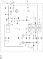
- a refrigeration system 10 for a motor vehicle comprises a refrigerant circuit 11, which can be operated both in a refrigeration system mode (also called AC mode for short) and in a heat pump mode.
- the refrigeration system 10 comprises a refrigerant compressor 12, an external heat exchanger 18, an internal heat exchanger 20, an evaporator 22 and an accumulator or refrigerant collector 24.
- the external heat exchanger 18 can be designed as a condenser or gas cooler. In particular, the external heat exchanger 18 can be flowed through bidirectionally in the embodiment shown.
- the evaporator 22 is shown here as an example as a front evaporator for a vehicle.
- the evaporator 22 also represents other possible evaporators in a vehicle, such as rear evaporators, which can be arranged parallel to one another in terms of flow.
- the refrigeration system 10 comprises at least one evaporator 22.
- a shut-off valve A4 is arranged downstream of the compressor 12.
- An expansion valve AE2 is provided upstream of the evaporator 22.
- the section from the compressor 12 to the external heat exchanger 18, to the internal heat exchanger 20 and to the evaporator 22 is referred to as the primary line 14.
- the refrigeration system 10 further comprises a heating register 26 (also referred to as a heating condenser or heating gas cooler).
- a shut-off valve A3 is arranged upstream of the heating register 26.
- a shut-off valve A1 is arranged downstream of the heating register 26.
- an expansion valve AE4 is arranged downstream of the heating register 26.
- the section from the compressor 12 to the heating register 26, to the expansion valve AE4 and to a branch Ab2 is referred to as the secondary branch 16.
- the secondary branch 16 comprises a heating branch 16.1, which extends from the shut-off valve A3 via the heating register 26 to the shut-off valve A1.
- the secondary branch 16 also comprises a reheat branch 16.2, which can be fluidly connected upstream to the heating register 26 and downstream to the external heat exchanger 5.
- the secondary branch 16 or the reheat branch 16.2 flows into the primary branch 14 at a branch point Ab2.
- the refrigeration system 10 comprises a further evaporator or chiller 28.
- the chiller 28 is provided in parallel flow terms to the evaporator 22.
- the chiller 28 can be used, for example, to cool an electrical component of the vehicle, but also to implement a water heat pump function using the waste heat from at least one electrical component.
- An expansion valve AE1 is connected upstream of the chiller 28.
- the refrigeration system 10 can also have an electric heating element 30, which is designed, for example, as a high-voltage PTC heating element.
- the electric heating element 30 serves as an additional heater for a supply air flow L guided into the vehicle interior.
- the electric heating element 30 can be accommodated together with the heating register 26 and the evaporator 22 in an air conditioning unit 32.
- the electric heating element 30 can be arranged downstream of the heating register 26.
- FIG.1 Check valves R1 and R2 are also visible. Furthermore, some sensors pT1 to pT5 are shown for measuring the pressure and/or temperature of the coolant. It should be noted that the number of sensors and their arrangement are only shown as examples. A refrigeration system 10 can also have fewer or more sensors. In the example shown, combined pressure/temperature sensors pT1 to pT5 are shown as sensors. However, it is also conceivable that separate sensors are used to measure pressure and temperature and, if necessary, are arranged spatially separated from one another along the coolant lines.
- the refrigeration system 10 can be operated in different modes, which are briefly described below.
- the refrigerant compressed to high pressure flows from the refrigerant compressor 12 with the shut-off valve A4 open into the external heat exchanger 18. From there, it flows to the high-pressure section of the internal heat exchanger 20 and the fully open expansion valve AE3.
- the refrigerant can flow to the expansion valve AE2 and into the interior evaporator 22 via a branch point Ab1 (evaporator section 22.1).
- the refrigerant can flow into the chiller 28 via a branch point Ab4 and the expansion valve AE1 (chiller section 28.1). From the evaporator 22 and/or the chiller 28, the refrigerant flows on the low-pressure side into the collector 24 and through the low-pressure section of the internal heat exchanger 20 back to the compressor 12.
- the heating branch 16.1 or the secondary branch 16 is shut off by means of the shut-off valve A3 so that hot refrigerant cannot flow through the heating register 26.
- the shut-off element A5 designed as a shut-off valve, can be opened so that the refrigerant can flow towards the collector 24 via the shut-off element A5 and the check valve R2, with the shut-off element A2 closed at the same time.
- shut-off valve A4 In heating mode of the refrigerant circuit 11, the shut-off valve A4 is closed and the shut-off valve A3 is opened so that hot refrigerant can flow into the heating branch 16.1.
- the refrigerant compressed by the refrigerant compressor 12 flows through the open shut-off valve A3 into the heating register 26.
- heat is released to a supply air flow L guided into the vehicle interior.
- the refrigerant then flows through the open shut-off valve A1 and the branch point Ab1.
- It is expanded by means of the expansion valve AE1 in the chiller 28 to absorb waste heat from the electrical and/or electronic components arranged in a coolant circuit 28.2.
- the expansion valves AE3 and AE4 are closed, the shut-off valve A5 is closed and the shut-off valve A2 is open.
- coolant removed during water heat pump operation can be extracted from a bidirectional branch 14.1 or the primary branch 14 via the shut-off valve A2 and fed to the collector 24 via the check valve R2.
- the refrigerant compressed by the refrigerant compressor 12 flows into the heating register via the open shut-off valve A3 to release heat to a supply air flow L. It is then expanded via the open shut-off valve A1 using the expansion valve AE3 in the external heat exchanger 18 to absorb heat from the ambient air. The refrigerant then flows via a heat pump return branch 15 to the collector 24 and back to the refrigerant compressor 12.
- the expansion valves AE1, AE2 and AE4 remain closed, as does the shut-off valve A5.
- An indirect delta connection can be realized by opening the shut-off valve A1 and releasing the refrigerant compressed by the refrigerant compressor 12 into the chiller 28 by means of the expansion valve AE1.
- no mass flow is generated on the coolant side, i.e. in the coolant circuit 28.2, i.e., for example, the fluid used as coolant, such as water or a water-glycol mixture, remains on the coolant side of the chiller 28 or the chiller 28 is not actively flowed through by coolant.
- the expansion valves AE2, AE3 and AE4 remain closed in this switching variant.
- the supply air flow L fed into the vehicle interior is first cooled and thus dehumidified by means of the evaporator 22.
- the supply air flow L can be completely or at least partially reheated by means of the heating register 26.
- the refrigeration system 10 in particular the air conditioning unit 32, has adjustable, in particular controllable and pivotable, temperature flaps 34 between the evaporator 22 and the heating register 26.
- a left and a right temperature flap 34L and 34R in Figure 1 shown schematically.
- the temperature flaps 34L, 34R can be adjusted or pivoted between an open position, which is referred to as the 100% position, and a closed position, which is referred to as the 0% position.
- the entire supply air flow L flowing through the evaporator 22 is guided over the heating register 26 and heated before it can flow into the passenger compartment of the vehicle.
- the entire supply air flow L flowing through the evaporator 22 flows in the bypass around the heating register 26 without heating and thus without absorbing heat into the passenger compartment.
- a reheat operation of the refrigerant circuit 11 or the refrigeration system 10 is carried out in different ways depending on the heat balance.
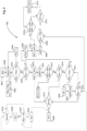
- a possible operating procedure 500 for the reheating or reheat operation is described using the flow chart of the Fig. 2 and having regard to the Fig.1 illustrated refrigeration system 10 and its components are explained by way of example.
- Such an operating method is usually implemented as a control program in a control unit for the refrigeration system or for the air conditioning in a vehicle.
- a post-heating operation is considered in which the coolant flows from the compressor 12 via the open shut-off valve A3 to the heating register 26 (heating condenser or heating gas cooler).
- the expansion valve AE4 is closed and the shut-off valve A1 is open so that the coolant can flow into the evaporator 22 via the expansion valve AE2.
- the expansion valves AE3 and AE1 are also closed.
- the post-heating operation is therefore achieved by connecting the refrigeration system 10 with as few active components as possible.
- reheating process 500 After the start (S501) of the refrigeration system 10, a transition to a reheating operation takes place at a point in time not specified here, which is referred to here as Reheat I (S502).
- a possible condition that must be met in order to start the reheating operation (S502) can be, for example, the measured ambient temperature.
- the reheating process can be activated in particular when the ambient temperature is up to 15°C, in particular from about 5°C to 15°C.
- the two temperature flaps 34L, 34R in this application are set to a target opening position TKso.
- TKso can be a specific opening value or can, as shown in the Fig. 2 shown at 502a, can be a range from an upper opening limit value TKo to a lower opening limit value TKu.
- a size or refrigeration system parameter used here as an example is the temperature flap opening TKan requested by a control unit. If a larger temperature flap opening TKan is requested, the heating requirement increases. If a smaller temperature flap opening TKan is requested, the heating requirement decreases.
- a temperature flap opening TKan requested by the system in the post-heating process considered here does not necessarily lead to a corresponding adjustment of the actual opening position or actual opening position TKis of the temperature flaps 34L, 34R.
- step S503 it is checked whether a requested temperature flap opening TKan is smaller than the upper opening limit value TKo and larger than the lower opening limit value TKu. If this is the case, the temperature flaps 34L, 34R can be adjusted in their actual opening position TKis according to step S504, which is indicated by the two arrows in step S504.
- the refrigeration circuit and/or the peripherals responsible for changing the climatic conditions remain unchanged. If the condition of step S503 is not met, it is checked in S505 whether the requested temperature flap opening is larger than the upper opening limit value TKo. Outside these limits, the refrigeration circuit and/or the peripherals responsible for changing the climatic conditions influencing periphery a change and thus reaction to the changed requirements and boundary conditions.
- the requested opening position TKan is smaller than the lower opening limit value TKu (S506).
- the heating requirement is decreasing and that the temperature flaps 34L, 34R should actually be closed further.
- the temperature flaps are not closed any further (yet).
- the target temperature of the supply air L exiting the evaporator 22 is increased.
- the target temperature for the temperature of the supply air L after flowing through the evaporator 22 is set depending on the heating output or the heating requirement.
- the pressure and temperature of the coolant are influenced, in particular in the heating register 26 in the refrigeration circuit 11, whereby as the target temperature at the evaporator 22 increases, the pressure pHD decreases (S508).
- the reheating process Reheat I is terminated and a switch is made to another reheating process, which is designated here as RH III (S513).
- a further system protection is used to evaluate whether a maximum pressure pHD or a maximum hot gas temperature tHG is reached.
- a branch to S513 takes place and thus a change to another reheat circuit, the so-called Reheat III.
- Reheat III it would also be conceivable to first carry out a further increase in the setpoint of the air temperature after the evaporator according to process step S507.
- a Mode change in Reheat III appears to be the preferred measure. Consequently, this is shown preferentially in the flow chart.
- the expansion valve AE4 can be opened (step by step) and the shut-off valve A1 is closed so that the refrigerant flows from the heating register 26 via the external heat exchanger 18 to the evaporator 22.
- adjustments SYS can be made on the system side for the operation of the refrigeration system 10, such as closing the temperature flaps 34L, 34R, whereby the system behavior of the refrigeration circuit must always be monitored.
- the target temperature is increased further according to S507 and steps S508 and S509 are repeated. As long as the heating requirement is decreasing, steps S507, S508, S509, S512 are repeated several times.
- step S505 the process is carried out as follows, starting from the steps S503 and S505 already mentioned above. If it is determined in S505 that the requested temperature flap opening TKan is greater than the upper opening limit value TKo, this means that the heating requirement is increasing and that the temperature flaps 34L, 34R should actually be opened further. However, according to the process described here, the temperature flaps are not opened any further (yet). Instead, in step S515, the target temperature for the supply air exiting the evaporator is determined. reduced. The setpoint temperature can be reduced incrementally. As a result, the high pressure pHD in the heating register 26 increases according to S516. The temperature T of the coolant in the heating register 26 also increases accordingly.
- the minimum adjustable target temperature can be between 2° and 4°, in particular the minimum adjustable target temperature is selected so that icing of the evaporator 22 due to condensate is prevented.
- S525 represents a change or switchover to another reheating process, which is designated here as RH III.
- RH III a change or switchover to another reheating process
- the expansion valve AE4 can be opened (step by step) and the shut-off valve A1 is closed so that the coolant flows from the heating register 26 via the external heat exchanger 18 to the evaporator 22.
- system-side adjustments SYS can be made for the operation of the refrigeration system 10, such as regulating the compressor 12 and/or adjusting other system parameters.
- S519 If it is determined in S519 that the target temperature is already set to a minimum value, a branch is made to S524, which illustrates the switching to another post-heating method RH II.
- switching on the electric heating element 30 can be considered for the post-heating process Reheat I considered here (S520). If the requested temperature flap opening TKan is still above the upper opening limit value TKo according to S521, the heating output or heat output of the electric heating element 30 is increased further. If the condition in S520 is no longer met due to a decreasing heating requirement, the heating output or heat output of the electric heating element 30 is reduced again according to S522. If the electric heating element 30 is no longer active, which is checked in S523, a branch is made to steps S510 and S511, so that if the heating requirement decreases or has decreased, the pressure can be adjusted by raising the target temperature (S507).
- the amount of supply air L supplied to the evaporator 22 can be adjusted in order to influence the heating output.
- the condition or quality of the supply air can be adjusted; in particular, fresh air or recirculated air or a mixture of fresh air and recirculated air can be supplied as supply air.
- Recirculated air can be taken from the interior of the vehicle and fresh air can be taken from the vehicle's surroundings.
- Fig.3 shows an embodiment of a refrigeration system 110 with which the above with reference to the Fig. 2 described post-heating process RH I can also be carried out.
- the refrigeration system 110 according to this embodiment is structurally simplified compared to the refrigeration system 110 in Fig.1 shown refrigeration system. 10.
- the refrigeration system 110 has no reheat branch (RH III) 16.2 ( Fig.1 ) no longer occurs. Accordingly, the external heat exchanger 18 can no longer be connected in series with the heating register 26.
- a check valve R3 is arranged between the heating register 26 and the expansion valve AE2 or the expansion valve AE1.
- the check valve R3 enables the flow of refrigerant from the heating register 26 to the evaporator 22 in accordance with the post-heating process described above, but prevents refrigerant flow in the opposite direction, i.e. when the refrigeration system is operating in AC mode.
- an expansion valve AE5 is shown in dashed lines downstream of the evaporator 22.
- Such an expansion valve AE5 can be used in all embodiments of the refrigeration system 10, 110 shown here ( Fig.1 , 3 , 4 ) instead of the check valve R1 shown.
- an intermediate pressure level can be achieved at the evaporator 22 that is above the icing limit. Any other heat source that is integrated can be operated at a low pressure level.
- Fig.4 shows the simplified refrigeration system with a further possible adjustment.
- a check valve R4 can be provided in addition to the existing expansion valve AE3, which is arranged between the internal heat exchanger 20 and the evaporator 22 or chiller 28.
- the check valve R4 is flowed through by refrigerant in AC operation of the refrigeration system 110.
- the check valve R4 prevents a flow of refrigerant from the heating register 26 to the high pressure side of the internal heat exchanger 20.
- TKso can be set from 60% to 90%, in particular to a value between 70% and 85%, based on the maximum opening position of 100%.
- TKu can be 78% and TKo can be 82%, so that TKso covers a range from 78% to 82%.
- the post-heating method described in this application can be achieved by connecting a minimal number of components of the refrigeration system 10, 110. This also offers the possibility of considering a simplified structure of the refrigeration system 110.
Landscapes
- Engineering & Computer Science (AREA)
- Physics & Mathematics (AREA)
- Thermal Sciences (AREA)
- Mechanical Engineering (AREA)
- General Engineering & Computer Science (AREA)
- Air-Conditioning For Vehicles (AREA)
Claims (10)
- Procédé de réchauffage (500) pour faire fonctionner une installation de réfrigération (10) pour un véhicule à moteur, dans lequel l'installation de réfrigération (10) comprend :un compresseur de réfrigérant (12) qui peut être connecté ou est connecté à une branche primaire (14) et à une branche secondaire (16) ;un échangeur de chaleur extérieur (18) qui est disposé dans la branche primaire (14) ;un évaporateur (22) qui est disposé dans la branche primaire (14) ;un registre de chauffage (26), qui est disposé dans la branche secondaire ;au moins un volet de température mobile (34L, 34R) qui est disposé devant ou derrière le registre de chauffage (26) par rapport à une direction d'écoulement d'air d'alimentation (L) ;au moins un organe d'arrêt (AE4, A1 ; R3 ; R4) disposé en aval du registre de chauffage (26) dans la branche secondaire (16) ;dans lequel le procédé de réchauffage comprend les étapes suivantes :réglage de l'au moins un organe d'arrêt (AE4, A1 ; R3, R4) sur une position dans laquelle le réfrigérant s'écoule en aval du registre de chauffage (26) dans l'évaporateur (22) en contournant l'échangeur de chaleur extérieur (18)dans lequel le procédé de réchauffage est caractérisé par les étapes suivantes :mesure de la température de l'air d'alimentation après son passage à travers l'évaporateur (22) et réglage d'une température de consigne (SP T_Verd) pour la température de l'air d'alimentation après son passage à travers l'évaporateur (22) en fonction d'un besoin de déshumidification ou/et de la puissance de chauffage ou/et du besoin de chauffage,réglage de l'au moins un volet de température (34L, 34R) sur une position d'ouverture de consigne (TKso) qui se situe dans une plage allant d'une valeur limite d'ouverture supérieure (TKo) à une valeur limite d'ouverture inférieure (TKu) ;maintien (502a) de la position d'ouverture de consigne (TKso) du volet de température (34L, 34R) lorsqu'une position d'ouverture demandée (TKan) est inférieure à la valeur limite d'ouverture inférieure (TKu) ou supérieure à la valeur limite d'ouverture supérieure (TKo) ; etpendant le maintien de la position d'ouverture de consigne (TKso), réduction progressive (S515) ou augmentation progressive (S507) de la température de consigne (SP T_Verd) en fonction de la demande de chauffage qui est déterminée à l'aide d'un paramètre d'installation de réfrigération (TKan), jusqu'à ce qu'un niveau de pression prédéterminé s'établisse côté haute pression au niveau du registre de chauffage (26) ou/et jusqu'à ce qu'une température de consigne maximale ou minimale (SP T_Verd) soit réglée (S512, S519).
- Procédé de réchauffage (500) selon la revendication 1, dans lequel la température ambiante est détectée et le procédé est mis en oeuvre lorsque la température ambiante est inférieure ou égale à 15 °C, en particulier lorsqu'elle se situe dans une plage d'environ 5° à 15°.
- Procédé de réchauffage (500) selon la revendication 1 ou 2, dans lequel, une fois le niveau de pression prédéterminé atteint, l'au moins un organe d'arrêt (AE4, A1) est ouvert de sorte que le réfrigérant s'écoule en aval du registre de chauffage (26) à travers l'échangeur de chaleur extérieur (18) avant de s'écouler à travers l'évaporateur (22).
- Procédé de réchauffage (500) selon l'une quelconque des revendications précédentes, dans lequel la position d'ouverture de consigne (TKso) du volet de température (34L, 34R) est réglée à une valeur comprise entre 60 % et 90 %, en particulier à une valeur comprise entre 70 % et 85 %, par rapport à une position d'ouverture maximale de 100 %.
- Procédé de réchauffage (500) selon l'une quelconque des revendications précédentes, dans lequel la quantité d'air d'alimentation (L) amenée vers l'évaporateur est réglée pour influencer la puissance de chauffage.
- Procédé de réchauffage selon la revendication 5, dans lequel la condition ou la qualité de l'air d'alimentation est réglée, en particulier de l'air frais ou de l'air recyclé ou un mélange d'air frais et d'air recyclé est amené.
- Installation de réfrigération (10) pour un véhicule à moteur, avecun compresseur de réfrigérant (12) qui peut être connecté ou est connecté à une branche primaire (14) et à une branche secondaire (16) ;un échangeur de chaleur extérieur (18) qui est disposé dans la branche primaire (14) ;un évaporateur (22) qui est disposé dans la branche primaire (14) ;un registre de chauffage (26), qui est disposé dans la branche secondaire (16) ;au moins un volet de température mobile (34L, 34R) qui est disposé devant ou derrière le registre de chauffage (26) par rapport à une direction d'écoulement d'air d'alimentation (L) ;au moins un organe d'arrêt (AE4, A1 ; R3 ; R4) disposé en aval du registre de chauffage (26) dans la branche secondaire (16) ;dans lequel l'installation de réfrigération (10) présente un dispositif de commande qui est configuré pour faire fonctionner l'installation de réfrigération (10) dans un mode de réchauffage selon l'une quelconque des revendications précédentes, etdans lequel, dans un tel mode de réchauffage, le réfrigérant, émanant du compresseur de réfrigérant (12), traverse consécutivement les composants suivants de l'installation de réfrigération (10) en contournant l'échangeur de chaleur extérieur (18) : registre de chauffage (26) dans la branche secondaire, évaporateur (22) dans la branche primaire.
- Installation de réfrigération (10) selon la revendication 7, dans laquelle l'échangeur de chaleur extérieur (18) peut être traversé de manière bidirectionnelle.
- Installation de réfrigération (10) selon la revendication 7 ou 8, dans laquelle une vanne d'arrêt (A1) est disposée entre le registre de chauffage (26) et l'évaporateur (22) et dans laquelle un robinet détendeur (AE4) est disposé entre le registre de chauffage (26) et l'échangeur de chaleur extérieur (18).
- Véhicule à moteur avec une installation de réfrigération (10) selon l'une quelconque des revendications 7 à 9.
Applications Claiming Priority (2)
| Application Number | Priority Date | Filing Date | Title |
|---|---|---|---|
| DE102019133489.6A DE102019133489A1 (de) | 2019-12-09 | 2019-12-09 | Nachheizverfahren zum Betreiben einer Kälteanlage für ein Kraftfahrzeug, Kälteanlage und Kraftfahrzeug mit einer solchen Kälteanlage |
| PCT/EP2020/077049 WO2021115654A1 (fr) | 2019-12-09 | 2020-09-28 | Procédé de réchauffage pour faire fonctionner un système de réfrigération pour un véhicule à moteur, système de réfrigération, et véhicule à moteur équipé d'un système de réfrigération de ce type |
Publications (2)
| Publication Number | Publication Date |
|---|---|
| EP4072874A1 EP4072874A1 (fr) | 2022-10-19 |
| EP4072874B1 true EP4072874B1 (fr) | 2024-09-18 |
Family
ID=72670711
Family Applications (1)
| Application Number | Title | Priority Date | Filing Date |
|---|---|---|---|
| EP20781487.2A Active EP4072874B1 (fr) | 2019-12-09 | 2020-09-28 | Procédé de réchauffage pour faire fonctionner un système de réfrigération pour un véhicule à moteur, système de réfrigération, et véhicule à moteur équipé d'un système de réfrigération de ce type |
Country Status (5)
| Country | Link |
|---|---|
| US (1) | US12296647B2 (fr) |
| EP (1) | EP4072874B1 (fr) |
| CN (1) | CN114786971B (fr) |
| DE (1) | DE102019133489A1 (fr) |
| WO (1) | WO2021115654A1 (fr) |
Families Citing this family (2)
| Publication number | Priority date | Publication date | Assignee | Title |
|---|---|---|---|---|
| DE102022213920A1 (de) * | 2022-12-19 | 2024-06-20 | Mahle International Gmbh | Kältemittelkreislauf |
| DE102023003208B3 (de) | 2023-08-03 | 2024-08-22 | Mercedes-Benz Group AG | Verfahren zum Betreiben einer Klimatisierungsvorrichtung eines Fahrzeugs und Klimatisierungsvorrichtung |
Family Cites Families (22)
| Publication number | Priority date | Publication date | Assignee | Title |
|---|---|---|---|---|
| JPS6012327A (ja) | 1983-07-01 | 1985-01-22 | Nissan Motor Co Ltd | 車両用空気調和装置 |
| JP3538845B2 (ja) * | 1991-04-26 | 2004-06-14 | 株式会社デンソー | 自動車用空調装置 |
| JP3985384B2 (ja) * | 1998-09-24 | 2007-10-03 | 株式会社デンソー | 冷凍サイクル装置 |
| EP1456046B1 (fr) | 2001-12-21 | 2008-07-09 | Daimler AG | Fabrication et regulation d'une climatisation destinee a un vehicule |
| DE102006002233A1 (de) * | 2006-01-17 | 2007-07-26 | Valeo Klimasysteme Gmbh | Heiz-und Klimaanlage mit Zusatzheizung |
| DE102010051471B4 (de) * | 2010-11-15 | 2025-07-10 | Audi Ag | Fahrzeug mit einer Klimaanlage |
| DE102011118162C5 (de) | 2011-11-10 | 2020-03-26 | Audi Ag | Kombinierte Kälteanlage und Wärmepumpe und Verfahren zum Betreiben der Anlage mit funktionsabhängiger Kältemittelverlagerung innerhalb des Kältemittelkreislaufes |
| DE102012108731B4 (de) * | 2012-09-17 | 2022-10-06 | Audi Ag | Klimaanlage für ein Kraftfahrzeug |
| US9656535B2 (en) * | 2012-09-17 | 2017-05-23 | Hanon Systems | Method for operating an air conditioner for a motor vehicle |
| FR2999689A1 (fr) | 2012-12-14 | 2014-06-20 | Valeo Systemes Thermiques | Circuit et procede de conditionnement d'air, notamment pour vehicule automobile |
| DE102014102078B4 (de) | 2014-02-19 | 2021-09-30 | Hanon Systems | Verfahren zum Abtauen eines Wärmeübertragers einer Klimaanlage eines Kraftfahrzeuges |
| DE102014017446A1 (de) | 2014-11-26 | 2015-06-25 | Daimler Ag | Klimatisierungseinrichtung für ein Fahrzeug sowie Verfahren zum Betreiben einer solchen Klimatisierungseinrichtung |
| DE102015002166B4 (de) * | 2015-02-19 | 2025-07-10 | Audi Ag | Fahrzeugklimaanlage mit Reheat-Betrieb und Fahrzeug damit |
| DE102015218824B4 (de) * | 2015-09-30 | 2024-09-12 | Bayerische Motoren Werke Aktiengesellschaft | Wärmepumpensystem und Verfahren zum Betrieb eines solchen |
| DE102015122721B4 (de) * | 2015-12-23 | 2019-09-05 | Hanon Systems | Klimatisierungssystem eines Kraftfahrzeugs und Verfahren zum Betreiben des Klimatisierungssystems |
| DE102016005782B4 (de) * | 2016-05-11 | 2018-10-18 | Audi Ag | Verfahren zum Betreiben einer Fahrzeugklimaanlage mit einem Kältemittelkreislauf |
| CN109328147A (zh) | 2016-06-16 | 2019-02-12 | 株式会社电装 | 制冷循环装置 |
| DE102016008743B3 (de) * | 2016-07-14 | 2017-10-19 | Audi Ag | Verfahren zum Betreiben einer Kälteanlage eines Fahrzeugs |
| DE102017211256B4 (de) * | 2017-07-03 | 2023-11-16 | Audi Ag | Kälteanlage für ein Fahrzeug mit einem einen Wärmeübertrager aufweisenden Kältemittelkreislauf |
| DE102017218424B4 (de) | 2017-10-16 | 2025-07-10 | Audi Ag | Verfahren zum Betreiben eines Kältemittelkreislaufs sowie Fahrzeugkälteanlage |
| JP2019137208A (ja) | 2018-02-09 | 2019-08-22 | サンデン・オートモーティブクライメイトシステム株式会社 | 車両用空気調和装置 |
| DE102018213232A1 (de) | 2018-08-07 | 2020-02-13 | Audi Ag | Verfahren zum Betreiben einer Kälteanlage für ein Fahrzeug mit einem eine Wärmepumpenfunktion aufweisenden Kältemittelkreislauf |
-
2019
- 2019-12-09 DE DE102019133489.6A patent/DE102019133489A1/de not_active Ceased
-
2020
- 2020-09-28 CN CN202080083075.4A patent/CN114786971B/zh active Active
- 2020-09-28 EP EP20781487.2A patent/EP4072874B1/fr active Active
- 2020-09-28 US US17/768,724 patent/US12296647B2/en active Active
- 2020-09-28 WO PCT/EP2020/077049 patent/WO2021115654A1/fr not_active Ceased
Also Published As
| Publication number | Publication date |
|---|---|
| EP4072874A1 (fr) | 2022-10-19 |
| CN114786971B (zh) | 2025-02-18 |
| CN114786971A (zh) | 2022-07-22 |
| US12296647B2 (en) | 2025-05-13 |
| US20240227499A9 (en) | 2024-07-11 |
| DE102019133489A1 (de) | 2021-06-10 |
| WO2021115654A1 (fr) | 2021-06-17 |
| US20240131896A1 (en) | 2024-04-25 |
Similar Documents
| Publication | Publication Date | Title |
|---|---|---|
| EP3833562B1 (fr) | Procédé de fonctionnement d'une installation de refroidissement pour un véhicule comportant un circuit d'agent réfrigérant comprenant une fonction de pompe à chaleur | |
| DE102020106625B4 (de) | Nachheizverfahren zum Betreiben einer Kälteanlage für ein Kraftfahrzeug, Kälteanlage und Kraftfahrzeug mit einer solchen Kälteanlage | |
| DE102008053320B4 (de) | Verfahren und System zur Steuerung einer Flugzeugklimaanlage mit optimiertem Treibstoffverbrauch | |
| DE102012210221B4 (de) | Verfahren zur Steuerung und/oder Regelung einer Kühleinrichtung für Fahrzeuge | |
| DE102010054448A1 (de) | Verfahren und Vorrichtung zur Steuerung einer Flugzeugklimaanlage | |
| EP4248150B1 (fr) | Installation frigorifique à fonction de pompe à chaleur pour véhicule automobile dotée d'un seul dispositif de détection côté basse pression | |
| DE102019133488A1 (de) | Nachheizverfahren zum Betreiben einer Kälteanlage für ein Kraftfahrzeug, Kälteanlage und Kraftfahrzeug mit einer solchen Kälteanlage | |
| EP4078050B1 (fr) | Contrôle de refroidissement pour un processus de réchauffage destiné à commander un système de refroidissement pour un véhicule à moteur, système de refroidissement, et véhicule à moteur ayant un tel système de refroidissement | |
| EP4072874B1 (fr) | Procédé de réchauffage pour faire fonctionner un système de réfrigération pour un véhicule à moteur, système de réfrigération, et véhicule à moteur équipé d'un système de réfrigération de ce type | |
| DE102020127528A1 (de) | Verfahren zum Betreiben einer Kälteanlage mit Wärmepumpenfunktion und Regenerationsfunktion für Wärmequellen, Kälteanlage und Kraftfahrzeug mit einer solchen Kälteanlage | |
| EP4232761B1 (fr) | Procédé pour maximiser un fluide frigorigène dans des sections de système actif d'un système de réfrigération, système de réfrigération et véhicule à moteur comprenant un tel système de réfrigération | |
| DE102020120687B4 (de) | Nachheizverfahren zum Betreiben einer Kälteanlage für ein Kraftfahrzeug, Kälteanlage und Kraftfahrzeug mit einer solchen Kälteanlage | |
| DE102014008274A1 (de) | Kraftfahrzeug mit Start-Stopp-Automatik und mit einem als Kältespeicher fungierenden Heizungswärmetauscher | |
| DE102020127300A1 (de) | Verfahren zum Betreiben einer Kälteanlage im Wärmepumpenbetrieb mit Abluftwärmenutzung, Kälteanlage und Kraftfahrzeug mit einer solchen Kälteanlage | |
| DE102019205901B4 (de) | Verfahren zum Betreiben einer Fahrzeug-Kälteanlage mit einem kombinierten Kälteanlagen- und Wärmepumpenbetrieb | |
| DE102020117816B4 (de) | Nachheizverfahren zum Betreiben einer Kälteanlage bei kritischer Heißgastemperatur, Kälteanlage und Kraftfahrzeug mit einer solchen Kälteanlage | |
| WO2024120855A1 (fr) | Unité de refroidissement comportant une fonction de pompe à chaleur et une section de dérivation traversée pendant le fonctionnement de la pompe à chaleur, et véhicule à moteur comportant une telle unité de refroidissement | |
| DE102019133546A1 (de) | Nachheizverfahren zum Betreiben einer Kälteanlage für ein Kraftfahrzeug, Kälteanlage und Kraftfahrzeug mit einer solchen Kälteanlage | |
| DE102021126837A1 (de) | Betriebsverfahren für eine Kälteanlage im Wärmepumpenbetrieb bei tiefen Umgebungstemperaturen und Kraftfahrzeug mit einer derart betriebenen Kälteanlage | |
| WO2023110175A1 (fr) | Procédé de fonctionnement d'un circuit de fluide frigorigène d'un véhicule automobile, et véhicule automobile | |
| DE102020125249A1 (de) | Verfahren zum Betreiben einer Kälteanlage im Kühlbetrieb, Kälteanlage und Kraftfahrzeug mit einer solchen Kälteanlage | |
| DE102017011480A1 (de) | Verfahren zum Betreiben eines Kältemittelverdichters in einer Kühivorrichtung eines Kraftwagens | |
| DE102024109389A1 (de) | Verfahren zum Betreiben einer Kälteanlage eines Kraftfahrzeugs im Nachheizbetrieb, Kälteanlage und Kraftfahrzeug | |
| DE102024131627A1 (de) | Kältemittelkreis mit Kühleinrichtung zwischen Verdichter und Heizwärmeübertrager für Reheatbetrieb, Kraftfahrzeug und Verfahren zum Betreiben eines Kältemittelkreises | |
| DE102024120444A1 (de) | Kältemittelkreis mit bei Wärmeüberschuss parallel geschalteten Kältemittelkühlern, Kraftfahrzeug und Verfahren zum Betreiben eines Kältemittelkreises |
Legal Events
| Date | Code | Title | Description |
|---|---|---|---|
| STAA | Information on the status of an ep patent application or granted ep patent |
Free format text: STATUS: UNKNOWN |
|
| STAA | Information on the status of an ep patent application or granted ep patent |
Free format text: STATUS: THE INTERNATIONAL PUBLICATION HAS BEEN MADE |
|
| PUAI | Public reference made under article 153(3) epc to a published international application that has entered the european phase |
Free format text: ORIGINAL CODE: 0009012 |
|
| STAA | Information on the status of an ep patent application or granted ep patent |
Free format text: STATUS: REQUEST FOR EXAMINATION WAS MADE |
|
| 17P | Request for examination filed |
Effective date: 20220711 |
|
| AK | Designated contracting states |
Kind code of ref document: A1 Designated state(s): AL AT BE BG CH CY CZ DE DK EE ES FI FR GB GR HR HU IE IS IT LI LT LU LV MC MK MT NL NO PL PT RO RS SE SI SK SM TR |
|
| DAV | Request for validation of the european patent (deleted) | ||
| DAX | Request for extension of the european patent (deleted) | ||
| P01 | Opt-out of the competence of the unified patent court (upc) registered |
Effective date: 20230529 |
|
| STAA | Information on the status of an ep patent application or granted ep patent |
Free format text: STATUS: EXAMINATION IS IN PROGRESS |
|
| 17Q | First examination report despatched |
Effective date: 20230825 |
|
| GRAP | Despatch of communication of intention to grant a patent |
Free format text: ORIGINAL CODE: EPIDOSNIGR1 |
|
| STAA | Information on the status of an ep patent application or granted ep patent |
Free format text: STATUS: GRANT OF PATENT IS INTENDED |
|
| RIC1 | Information provided on ipc code assigned before grant |
Ipc: F25B 41/20 20210101ALI20240515BHEP Ipc: F25B 41/40 20210101ALI20240515BHEP Ipc: F25B 25/00 20060101ALI20240515BHEP Ipc: F25B 49/02 20060101ALI20240515BHEP Ipc: F25B 40/00 20060101ALI20240515BHEP Ipc: F25B 13/00 20060101ALI20240515BHEP Ipc: F25B 5/00 20060101ALI20240515BHEP Ipc: F25B 5/02 20060101ALI20240515BHEP Ipc: F25B 30/00 20060101ALI20240515BHEP Ipc: B60H 1/32 20060101ALI20240515BHEP Ipc: B60H 1/00 20060101AFI20240515BHEP |
|
| INTG | Intention to grant announced |
Effective date: 20240612 |
|
| GRAS | Grant fee paid |
Free format text: ORIGINAL CODE: EPIDOSNIGR3 |
|
| GRAA | (expected) grant |
Free format text: ORIGINAL CODE: 0009210 |
|
| STAA | Information on the status of an ep patent application or granted ep patent |
Free format text: STATUS: THE PATENT HAS BEEN GRANTED |
|
| AK | Designated contracting states |
Kind code of ref document: B1 Designated state(s): AL AT BE BG CH CY CZ DE DK EE ES FI FR GB GR HR HU IE IS IT LI LT LU LV MC MK MT NL NO PL PT RO RS SE SI SK SM TR |
|
| REG | Reference to a national code |
Ref country code: GB Ref legal event code: FG4D Free format text: NOT ENGLISH |
|
| REG | Reference to a national code |
Ref country code: CH Ref legal event code: EP |
|
| REG | Reference to a national code |
Ref country code: DE Ref legal event code: R096 Ref document number: 502020009285 Country of ref document: DE |
|
| REG | Reference to a national code |
Ref country code: IE Ref legal event code: FG4D Free format text: LANGUAGE OF EP DOCUMENT: GERMAN |
|
| REG | Reference to a national code |
Ref country code: LT Ref legal event code: MG9D |
|
| PG25 | Lapsed in a contracting state [announced via postgrant information from national office to epo] |
Ref country code: NO Free format text: LAPSE BECAUSE OF FAILURE TO SUBMIT A TRANSLATION OF THE DESCRIPTION OR TO PAY THE FEE WITHIN THE PRESCRIBED TIME-LIMIT Effective date: 20241218 |
|
| PG25 | Lapsed in a contracting state [announced via postgrant information from national office to epo] |
Ref country code: GR Free format text: LAPSE BECAUSE OF FAILURE TO SUBMIT A TRANSLATION OF THE DESCRIPTION OR TO PAY THE FEE WITHIN THE PRESCRIBED TIME-LIMIT Effective date: 20241219 Ref country code: FI Free format text: LAPSE BECAUSE OF FAILURE TO SUBMIT A TRANSLATION OF THE DESCRIPTION OR TO PAY THE FEE WITHIN THE PRESCRIBED TIME-LIMIT Effective date: 20240918 |
|
| PG25 | Lapsed in a contracting state [announced via postgrant information from national office to epo] |
Ref country code: BG Free format text: LAPSE BECAUSE OF FAILURE TO SUBMIT A TRANSLATION OF THE DESCRIPTION OR TO PAY THE FEE WITHIN THE PRESCRIBED TIME-LIMIT Effective date: 20240918 |
|
| PG25 | Lapsed in a contracting state [announced via postgrant information from national office to epo] |
Ref country code: LV Free format text: LAPSE BECAUSE OF FAILURE TO SUBMIT A TRANSLATION OF THE DESCRIPTION OR TO PAY THE FEE WITHIN THE PRESCRIBED TIME-LIMIT Effective date: 20240918 |
|
| PG25 | Lapsed in a contracting state [announced via postgrant information from national office to epo] |
Ref country code: HR Free format text: LAPSE BECAUSE OF FAILURE TO SUBMIT A TRANSLATION OF THE DESCRIPTION OR TO PAY THE FEE WITHIN THE PRESCRIBED TIME-LIMIT Effective date: 20240918 |
|
| REG | Reference to a national code |
Ref country code: NL Ref legal event code: MP Effective date: 20240918 |
|
| PG25 | Lapsed in a contracting state [announced via postgrant information from national office to epo] |
Ref country code: RS Free format text: LAPSE BECAUSE OF FAILURE TO SUBMIT A TRANSLATION OF THE DESCRIPTION OR TO PAY THE FEE WITHIN THE PRESCRIBED TIME-LIMIT Effective date: 20241218 |
|
| PG25 | Lapsed in a contracting state [announced via postgrant information from national office to epo] |
Ref country code: RS Free format text: LAPSE BECAUSE OF FAILURE TO SUBMIT A TRANSLATION OF THE DESCRIPTION OR TO PAY THE FEE WITHIN THE PRESCRIBED TIME-LIMIT Effective date: 20241218 Ref country code: NO Free format text: LAPSE BECAUSE OF FAILURE TO SUBMIT A TRANSLATION OF THE DESCRIPTION OR TO PAY THE FEE WITHIN THE PRESCRIBED TIME-LIMIT Effective date: 20241218 Ref country code: LV Free format text: LAPSE BECAUSE OF FAILURE TO SUBMIT A TRANSLATION OF THE DESCRIPTION OR TO PAY THE FEE WITHIN THE PRESCRIBED TIME-LIMIT Effective date: 20240918 Ref country code: HR Free format text: LAPSE BECAUSE OF FAILURE TO SUBMIT A TRANSLATION OF THE DESCRIPTION OR TO PAY THE FEE WITHIN THE PRESCRIBED TIME-LIMIT Effective date: 20240918 Ref country code: GR Free format text: LAPSE BECAUSE OF FAILURE TO SUBMIT A TRANSLATION OF THE DESCRIPTION OR TO PAY THE FEE WITHIN THE PRESCRIBED TIME-LIMIT Effective date: 20241219 Ref country code: FI Free format text: LAPSE BECAUSE OF FAILURE TO SUBMIT A TRANSLATION OF THE DESCRIPTION OR TO PAY THE FEE WITHIN THE PRESCRIBED TIME-LIMIT Effective date: 20240918 Ref country code: BG Free format text: LAPSE BECAUSE OF FAILURE TO SUBMIT A TRANSLATION OF THE DESCRIPTION OR TO PAY THE FEE WITHIN THE PRESCRIBED TIME-LIMIT Effective date: 20240918 |
|
| PG25 | Lapsed in a contracting state [announced via postgrant information from national office to epo] |
Ref country code: NL Free format text: LAPSE BECAUSE OF FAILURE TO SUBMIT A TRANSLATION OF THE DESCRIPTION OR TO PAY THE FEE WITHIN THE PRESCRIBED TIME-LIMIT Effective date: 20240918 |
|
| PG25 | Lapsed in a contracting state [announced via postgrant information from national office to epo] |
Ref country code: PT Free format text: LAPSE BECAUSE OF FAILURE TO SUBMIT A TRANSLATION OF THE DESCRIPTION OR TO PAY THE FEE WITHIN THE PRESCRIBED TIME-LIMIT Effective date: 20250120 Ref country code: IS Free format text: LAPSE BECAUSE OF FAILURE TO SUBMIT A TRANSLATION OF THE DESCRIPTION OR TO PAY THE FEE WITHIN THE PRESCRIBED TIME-LIMIT Effective date: 20250118 |
|
| PG25 | Lapsed in a contracting state [announced via postgrant information from national office to epo] |
Ref country code: RO Free format text: LAPSE BECAUSE OF FAILURE TO SUBMIT A TRANSLATION OF THE DESCRIPTION OR TO PAY THE FEE WITHIN THE PRESCRIBED TIME-LIMIT Effective date: 20240918 Ref country code: SM Free format text: LAPSE BECAUSE OF FAILURE TO SUBMIT A TRANSLATION OF THE DESCRIPTION OR TO PAY THE FEE WITHIN THE PRESCRIBED TIME-LIMIT Effective date: 20240918 |
|
| PG25 | Lapsed in a contracting state [announced via postgrant information from national office to epo] |
Ref country code: ES Free format text: LAPSE BECAUSE OF FAILURE TO SUBMIT A TRANSLATION OF THE DESCRIPTION OR TO PAY THE FEE WITHIN THE PRESCRIBED TIME-LIMIT Effective date: 20240918 |
|
| PG25 | Lapsed in a contracting state [announced via postgrant information from national office to epo] |
Ref country code: EE Free format text: LAPSE BECAUSE OF FAILURE TO SUBMIT A TRANSLATION OF THE DESCRIPTION OR TO PAY THE FEE WITHIN THE PRESCRIBED TIME-LIMIT Effective date: 20240918 |
|
| PG25 | Lapsed in a contracting state [announced via postgrant information from national office to epo] |
Ref country code: PL Free format text: LAPSE BECAUSE OF FAILURE TO SUBMIT A TRANSLATION OF THE DESCRIPTION OR TO PAY THE FEE WITHIN THE PRESCRIBED TIME-LIMIT Effective date: 20240918 Ref country code: CZ Free format text: LAPSE BECAUSE OF FAILURE TO SUBMIT A TRANSLATION OF THE DESCRIPTION OR TO PAY THE FEE WITHIN THE PRESCRIBED TIME-LIMIT Effective date: 20240918 |
|
| PG25 | Lapsed in a contracting state [announced via postgrant information from national office to epo] |
Ref country code: IT Free format text: LAPSE BECAUSE OF FAILURE TO SUBMIT A TRANSLATION OF THE DESCRIPTION OR TO PAY THE FEE WITHIN THE PRESCRIBED TIME-LIMIT Effective date: 20240918 Ref country code: SK Free format text: LAPSE BECAUSE OF FAILURE TO SUBMIT A TRANSLATION OF THE DESCRIPTION OR TO PAY THE FEE WITHIN THE PRESCRIBED TIME-LIMIT Effective date: 20240918 |
|
| REG | Reference to a national code |
Ref country code: CH Ref legal event code: PL |
|
| PG25 | Lapsed in a contracting state [announced via postgrant information from national office to epo] |
Ref country code: LU Free format text: LAPSE BECAUSE OF NON-PAYMENT OF DUE FEES Effective date: 20240928 |
|
| REG | Reference to a national code |
Ref country code: DE Ref legal event code: R097 Ref document number: 502020009285 Country of ref document: DE |
|
| PG25 | Lapsed in a contracting state [announced via postgrant information from national office to epo] |
Ref country code: MC Free format text: LAPSE BECAUSE OF FAILURE TO SUBMIT A TRANSLATION OF THE DESCRIPTION OR TO PAY THE FEE WITHIN THE PRESCRIBED TIME-LIMIT Effective date: 20240918 |
|
| PG25 | Lapsed in a contracting state [announced via postgrant information from national office to epo] |
Ref country code: DK Free format text: LAPSE BECAUSE OF FAILURE TO SUBMIT A TRANSLATION OF THE DESCRIPTION OR TO PAY THE FEE WITHIN THE PRESCRIBED TIME-LIMIT Effective date: 20240918 |
|
| REG | Reference to a national code |
Ref country code: BE Ref legal event code: MM Effective date: 20240930 |
|
| PG25 | Lapsed in a contracting state [announced via postgrant information from national office to epo] |
Ref country code: BE Free format text: LAPSE BECAUSE OF NON-PAYMENT OF DUE FEES Effective date: 20240930 |
|
| PG25 | Lapsed in a contracting state [announced via postgrant information from national office to epo] |
Ref country code: CH Free format text: LAPSE BECAUSE OF NON-PAYMENT OF DUE FEES Effective date: 20240930 |
|
| PLBE | No opposition filed within time limit |
Free format text: ORIGINAL CODE: 0009261 |
|
| STAA | Information on the status of an ep patent application or granted ep patent |
Free format text: STATUS: NO OPPOSITION FILED WITHIN TIME LIMIT |
|
| PG25 | Lapsed in a contracting state [announced via postgrant information from national office to epo] |
Ref country code: IE Free format text: LAPSE BECAUSE OF NON-PAYMENT OF DUE FEES Effective date: 20240928 |
|
| 26N | No opposition filed |
Effective date: 20250619 |
|
| PG25 | Lapsed in a contracting state [announced via postgrant information from national office to epo] |
Ref country code: SE Free format text: LAPSE BECAUSE OF FAILURE TO SUBMIT A TRANSLATION OF THE DESCRIPTION OR TO PAY THE FEE WITHIN THE PRESCRIBED TIME-LIMIT Effective date: 20240918 |
|
| PGFP | Annual fee paid to national office [announced via postgrant information from national office to epo] |
Ref country code: DE Payment date: 20250930 Year of fee payment: 6 |
|
| PGFP | Annual fee paid to national office [announced via postgrant information from national office to epo] |
Ref country code: GB Payment date: 20250923 Year of fee payment: 6 |
|
| PGFP | Annual fee paid to national office [announced via postgrant information from national office to epo] |
Ref country code: AT Payment date: 20251020 Year of fee payment: 5 Ref country code: FR Payment date: 20250925 Year of fee payment: 6 |
|
| PG25 | Lapsed in a contracting state [announced via postgrant information from national office to epo] |
Ref country code: CY Free format text: LAPSE BECAUSE OF FAILURE TO SUBMIT A TRANSLATION OF THE DESCRIPTION OR TO PAY THE FEE WITHIN THE PRESCRIBED TIME-LIMIT; INVALID AB INITIO Effective date: 20200928 |
|
| PG25 | Lapsed in a contracting state [announced via postgrant information from national office to epo] |
Ref country code: HU Free format text: LAPSE BECAUSE OF FAILURE TO SUBMIT A TRANSLATION OF THE DESCRIPTION OR TO PAY THE FEE WITHIN THE PRESCRIBED TIME-LIMIT; INVALID AB INITIO Effective date: 20200928 |