EP4072905B1 - Ensembles d'accouplement de module de coussin de sécurité gonflable de conducteur - Google Patents
Ensembles d'accouplement de module de coussin de sécurité gonflable de conducteur Download PDFInfo
- Publication number
- EP4072905B1 EP4072905B1 EP20828926.4A EP20828926A EP4072905B1 EP 4072905 B1 EP4072905 B1 EP 4072905B1 EP 20828926 A EP20828926 A EP 20828926A EP 4072905 B1 EP4072905 B1 EP 4072905B1
- Authority
- EP
- European Patent Office
- Prior art keywords
- spring
- airbag module
- mounting
- coupling
- prong
- Prior art date
- Legal status (The legal status is an assumption and is not a legal conclusion. Google has not performed a legal analysis and makes no representation as to the accuracy of the status listed.)
- Active
Links
Images


Classifications
-
- B—PERFORMING OPERATIONS; TRANSPORTING
- B60—VEHICLES IN GENERAL
- B60R—VEHICLES, VEHICLE FITTINGS, OR VEHICLE PARTS, NOT OTHERWISE PROVIDED FOR
- B60R21/00—Arrangements or fittings on vehicles for protecting or preventing injuries to occupants or pedestrians in case of accidents or other traffic risks
- B60R21/02—Occupant safety arrangements or fittings, e.g. crash pads
- B60R21/16—Inflatable occupant restraints or confinements designed to inflate upon impact or impending impact, e.g. air bags
- B60R21/20—Arrangements for storing inflatable members in their non-use or deflated condition; Arrangement or mounting of air bag modules or components
- B60R21/203—Arrangements for storing inflatable members in their non-use or deflated condition; Arrangement or mounting of air bag modules or components in steering wheels or steering columns
- B60R21/2035—Arrangements for storing inflatable members in their non-use or deflated condition; Arrangement or mounting of air bag modules or components in steering wheels or steering columns using modules containing inflator, bag and cover attachable to the steering wheel as a complete sub-unit
-
- B—PERFORMING OPERATIONS; TRANSPORTING
- B60—VEHICLES IN GENERAL
- B60R—VEHICLES, VEHICLE FITTINGS, OR VEHICLE PARTS, NOT OTHERWISE PROVIDED FOR
- B60R21/00—Arrangements or fittings on vehicles for protecting or preventing injuries to occupants or pedestrians in case of accidents or other traffic risks
- B60R21/02—Occupant safety arrangements or fittings, e.g. crash pads
- B60R21/16—Inflatable occupant restraints or confinements designed to inflate upon impact or impending impact, e.g. air bags
- B60R21/23—Inflatable members
- B60R21/231—Inflatable members characterised by their shape, construction or spatial configuration
-
- B—PERFORMING OPERATIONS; TRANSPORTING
- B62—LAND VEHICLES FOR TRAVELLING OTHERWISE THAN ON RAILS
- B62D—MOTOR VEHICLES; TRAILERS
- B62D1/00—Steering controls, i.e. means for initiating a change of direction of the vehicle
- B62D1/02—Steering controls, i.e. means for initiating a change of direction of the vehicle vehicle-mounted
- B62D1/04—Hand wheels
-
- B—PERFORMING OPERATIONS; TRANSPORTING
- B60—VEHICLES IN GENERAL
- B60Y—INDEXING SCHEME RELATING TO ASPECTS CROSS-CUTTING VEHICLE TECHNOLOGY
- B60Y2304/00—Optimising design; Manufacturing; Testing
- B60Y2304/07—Facilitating assembling or mounting
Definitions
- Airbag cushions are often assembled within steering wheels. However, in newer vehicles, steering wheels tend to incorporate more features and associated airbag modules are often more compact. Thus, it is important for airbag module interfaces to provide a small footprint and/or to otherwise impact the space and/or design of other features as minimally as possible. In addition, the ability to quickly and easily couple, and in some cases decouple, an airbag module to a steering wheel may be important.
- FR 2 790 044 A1 discloses an airbag assembly, comprising an airbag module, a mounting interface for coupling the airbag module to a vehicle structure, whereby the mounting interface comprises opposing mounting surfaces, a spring configured to engage the mounting interface, wherein the spring defines a perimeter comprising at least three sides and a coupling prong configured to engage the spring to secure the airbag module to the mounting interface, wherein the coupling prong is configured to engage one of the at least three sides.
- the inventive concepts disclosed herein may therefore provide a coupling interface/assembly having a relatively small footprint and/or one that is simple, easy to use, and/or provides the ability to uncouple the assembly for servicing and/or replacement of the airbag module as needed.
- the coupling assembly for coupling a driver airbag module to a steering wheel comprises a spring, such as a spring clip, which defines a perimeter, in some embodiments within a single plane, that comprises at least three sides and/or legs.
- a first side/leg of the at least three sides/legs extends opposite from a second side/leg of the at least three sides/legs.
- the first side/le is at least partially angled towards the second side/leg of the spring at an acute angle, such as an angle of between about 20 and about 40 degrees.
- the first and second sides/legs of the spring are connected along a third side/leg of the at least three sides/legs of the spring.
- the assembly may further comprise a spring mounting structure, which may be configured to provide a guiding interface for coupling the spring to the steering wheel.
- the spring mounting structure may comprise a linear interface surface configured to engage the first side/leg of the spring to inhibit rotation of the first side/leg of the spring as the second side/leg of the spring rotates during assembly.
- the spring may be configured to inhibit further rotation but allow a translation of the spring. Such translation may be provided by simply inserting a prong or other protruding member through the opening to engage the spring.
- the third side/leg may extend from the first and second sides/legs of the spring at an at least substantially perpendicular angle. In some embodiments, the third side/leg may extend from the first and/or second sides/legs of the spring at an angle between about 70 and about 90 degrees. Of course, this angle need not be perpendicular, nor at least substantially perpendicular, in other embodiments.
- first and/or second sides/legs of the spring may each comprise a straight portion extending from the third side/leg at the at least substantially perpendicular angle and an angled portion extending from the straight portion.
- the angled portions of the first and second sides/legs may be angled towards one another.
- the spring may further comprise a fourth side/leg opposite the third side/leg, which may extend at least substantially parallel to the third side/leg so as to at least substantially define a trapezoid in shape.
- the first side/leg may be symmetrical with the second side/leg about an axis of the spring extending between the third side/leg and the fourth side/leg.
- the airbag module and/or the steering wheel may comprise a plurality of springs and a plurality of corresponding spring mounting structures.
- the assembly may comprise an airbag module and one or more mounting interfaces for coupling the airbag module to a vehicle structure.
- the mounting interface may comprise opposing mounting structures and/or surfaces.
- the assembly may further comprise one or more springs configured to engage the mounting interface(s). Each spring may define a perimeter comprising at least three sides and/or legs.
- the assembly may further comprise one or more coupling prongs each configured to engage a spring to secure the airbag module to the mounting interface.
- the coupling prong(s) may be configured to engage one or more of the at least three sides and/or legs and translate the spring(s) during securement of the airbag module to the mounting interface in a first direction.
- the airbag module may comprise a driver airbag module and the vehicle structure may comprise a vehicle steering wheel.
- the opposing mounting surfaces may be defined by opposing mounting structures of the mounting interface.
- the coupling prong(s) may be attached to and/or extend from the airbag module.
- the coupling prong(s) may comprise a ramped tip and/or otherwise be configured to translate the spring during securement of the airbag module to the mounting interface.
- the coupling prong(s) may further comprise a hooked and/or recessed portion adjacent to the ramped tip. The hooked/recessed portion may be configured to receive a portion of the spring after the ramped tip has extended past the spring to allow the spring to translate in a second direction distinct from the first direction.
- the second direction may be opposite, or at least substantially opposite, from the first direction.
- the coupling prong(s) may be attached to and/or extend from a portion of the vehicle, such as the steering wheel.
- the mounting interface(s) may comprise an opening configured to receive a coupling prong.
- the opening may be positioned such that the coupling prong extends into a central region of the spring defined by the perimeter of the spring, and the opening may at least partially overlap with a position of the spring when the spring is coupled with the mounting interface to allow the coupling prong to contact and move the spring during assembly.
- the method may comprise coupling a spring to a mounting interface.
- the spring may define a perimeter, which, in some embodiments, may comprise at least three sides.
- the step of coupling the spring to the mounting interface may comprise engaging a first side of the spring with a first surface of the mounting interface while rotating a second side of the spring opposite the first side.
- the method may further comprise inserting a coupling prong through an opening formed in the mounting interface, which may translate the spring in a first direction and then in a second direction, which may be opposite, or at least substantially opposite, the first direction.
- the coupling prong may comprise a ramped tip.
- the step of inserting the coupling prong through the opening formed in the mounting interface may comprise engaging a third side of the spring extending between the first and second sides of the spring with a surface of the ramped tip.
- the coupling prong may further comprise a hooked portion adjacent to the ramped tip, and the step of inserting the coupling prong through the opening formed in the mounting interface may further comprise allowing the spring to extend into the hooked portion after the ramped tip has extended past the spring to allow the spring to translate in the second direction.
- the first surface may comprise a flat surface
- the step of coupling the spring to the mounting interface may comprise engaging the first side of the spring with the flat surface of the mounting interface to prevent rotation of the first side of the spring while the second side of the spring pivots about a second surface of the mounting interface.
- Some implementations may further comprise releasing the driver airbag module from the steering wheel, which may take place, for example, by translating the spring away from the coupling prong and withdrawing the coupling prong from the opening.
- the spring may, in some embodiments and implementations, comprise a third side and/or leg extending between the first and second sides/legs.
- the third side/leg may engage the coupling prong during the step of inserting the coupling prong through the opening formed in the mounting interface.
- the spring may further comprise a fourth side/leg opposite the third side/leg.
- the step of releasing the driver airbag module from the steering wheel may comprise engaging the fourth side to translate the spring away from the coupling prong.
- the term “substantially” refers to the complete or nearly complete extent or degree of an action, characteristic, property, state, structure, item, or result to function as indicated.
- an object that is “substantially” cylindrical or “substantially” perpendicular would mean that the object/feature is either cylindrical/perpendicular or nearly cylindrical/perpendicular so as to result in the same or nearly the same function.
- the exact allowable degree of deviation provided by this term may depend on the specific context.
- the use of “substantially” is equally applicable when used in a negative connotation to refer to the complete or near complete lack of an action, characteristic, property, state, structure, item, or result.
- structure which is "substantially free of" a bottom would either completely lack a bottom or so nearly completely lack a bottom that the effect would be effectively the same as if it completely lacked a bottom.
- the term “about” is used to provide flexibility to a numerical range endpoint by providing that a given value may be “a little above” or “a little below” the endpoint while still accomplishing the function associated with the range.
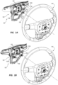
- FIGS. 1A and 1B depict an assembly 100 comprising an airbag module 102 configured to be coupled to a steering wheel 104 according to some embodiments.
- a coupling assembly may be provided to facilitate mounting or otherwise coupling of airbag module 102, which comprises an inflator 105, to steering wheel 104, which may comprise one or more mounting interfaces, such as mounting interfaces 110A and 110B shown in these figures. It should be understood that these mounting interfaces would typically comprise certain elements from both airbag module 102 and other elements on steering wheel 104. However, as those of ordinary skill in the art will appreciate, the depicted elements may be positioned at alternative locations as desired. For example, although most of the elements are shown in the exploded views of FIGS.
- one or more of the elements shown on airbag module 102 may instead be positioned on steering wheel 104, and vice versa.
- one or more of the mounting elements depicted and discussed in greater detail below may be overmolded to, for example, a horn plate or another portion of steering wheel 104.
- FIGS. 1-2 further comprises a plurality of spring clips 150 each configured to couple to one mounting interface 110 to lock airbag module 102 to steering wheel 104.
- any number of such mounting interfaces 110 may be used.
- a single, preferably centralized mounting interface 110 may be sufficient to secure airbag module 102 in place.
- four such mounting interfaces 110 may be used, or any other number as desired.
- FIG. 1A depicts spring clips 150 detached from their respective mounting interfaces 110 and FIG. 1B depicts them secured in place.
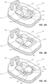
- FIGS. 3A and 3B depict close-up views of a mounting interface 110 with spring clip 150 positioned therein.
- spring clip 150 may, in some embodiments, comprise four legs or sides extending about an open center region.
- a coupling prong 160 or other protruding coupling member may be inserted within this center region during assembly to lock the spring clip 150 in place.
- Spring clip 150 comprises a first leg/side 152 that extends opposite a second leg/side 154.
- each of these legs/sides comprises a first portion that extends parallel to the corresponding opposite leg/side and then angels towards one another at an acute angle ⁇ , which may be between about 20 and about 40 degrees in some embodiments. In more preferred embodiments, angle ⁇ , may be between about 20 and about 40 degrees
- opposing legs 152/154 are symmetrical, both with respect to a central axis of spring clip 150 and about a central axis of mounting interface 110.
- spring clip 150 is preferably formed such that each of the various sides extends parallel to one another in the same plane but, as described herein and depicted in the accompanying figures, may be angled towards one another within this plane.
- Opposing sides/legs 152 and 154 are connected along a third side/leg 156, which may extend perpendicular, or at least substantially perpendicular, to sides/legs 152 and/or 154.
- a partial side/leg 158 may be provided, which, as discussed below, may provide for an interface with a tool that may be used to release spring clip 150 and thereby release an airbag module from a steering wheel or another mounting surface/element of a vehicle.
- spring 150 defines a trapezoid in shape.
- the tool interface region is outside of the aforementioned open/central region within which the prong 160 extends to lock the spring clip 150 in place.
- the mounting interface 110 comprises an opening 111 and one or more surrounding guiding/mounting features for guiding spring 150 and/or locking spring 150 into place.
- a first mounting structure 112 is provided on one side of interface 110 and a second mounting structure 114 is provided on the opposite side.
- mounting structure 112 is configured to engage the angled leg 154 of spring 150 and, similarly, mounting structure 114 is configured to engage the angled portion of leg 152 of spring 150.
- mounting structures 112/114 may comprise various features/surfaces to facilitate desired flexing/movement of spring 150 during assembly and/or disassembly.
- an angled surface may be provided that may engage an angled surface of one of the sides of spring 150 to inhibit rotation of that side while the opposite side has a point contact to facilitate rotation of just one side of spring 150 during installation.
- one or both of mounting structures 112/114 may comprise an overhang defining an underlying recessed region to allow spring 150 to flex over the overhang and seat within the recess defined thereunder to secure spring 150 in place and prevent unintentional disassembly.
- guiding/mounting structures 116 and 118 are provided opposite one another on opposing sides of opening 111. Structures 116 may keep spring 150 in position and guide it back and forth during various stages of installation/assembly, as discussed throughout this disclosure. As shown in FIG. 3B , once spring 150 is in place using one or more of the aforementioned guiding/mounting structures, a coupling prong 160, which may extend from and be a part of either airbag module 102 or steering wheel 104, may be extended through opening 111 to secure the airbag module 102 to the steering wheel 104 or, in other embodiments, to secure an airbag module to another suitable location within a vehicle.
- An adjacent structure 119 may also be provided if desired, which may be used to guide a tool for uninstalling airbag module 102 and/or may be used to confine spring 150, such as to prevent spring 150 from translating too far in the absence of the presence of prong 160.
- structure 119 may, in some embodiments, comprise a central opening to allow a tool to extend therethrough. The walls defining the opening may be used to engage spring 150 during use to, again, inhibit undue translation of spring 150 during installation.
- FIGS. 4A and 4B illustrate possible steps for uninstallation of airbag module 102 from steering wheel 104.
- a tool 50 may be used to contact leg 158 and to apply a force (downward from the perspective of these figures, as indicated by the arrow in FIG. 4A ) to allow spring 150 to translate away from prong 160 to allow prong 160 to be removed.
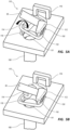
- FIGS. 5A and 5B illustrate steps involved in coupling of spring 150 to interface 110.
- spring 150 may initially be positioned about one side of interface 110, namely, mounting structure 112.
- Spring 150 may then be rotated so that the leg opposite the leg contacting mounting structure 112 rotates about the opposite mounting structure 114, as indicated by the arrow in FIG. 5A .
- linear contact is maintained between spring 150 on this side and mounting structure 112 so as provide a pivoting surface to inhibit rotation of a first side of the spring 150 as a second side of the spring 150 opposite the first side rotates.
- coupling of spring 150 to interface 110 involves both a translational and a rotational movement.
- a tool 55 may be used to facilitate this coupling procedure.
- prongs 160 may be extended through openings 111 to secure the mounting of, for example, airbag module 102 to steering wheel 104.
- FIGS. 6A-6C These steps are illustrated in FIGS. 6A-6C .
- interface 110 is configured to lock spring clip 150 in place and to, as shown in FIGS. 6A-6C , only allow for a translation of the spring clip 150 to accommodate a pin/prong 160 to lock two structures in place, such as an airbag module to a steering wheel.
- FIG. 6A depicts the initial stage of this process in which spring clip 150 is positioned and confined about structures 112-18. As also shown in this figure, spring clip 150 partially extends over opening 111, which allows prong 160, during entry therethrough, to automatically reposition spring clip 150 to accommodate prong 160 and then, as discussed below, automatically slide back into place to lock prong 160 therein.
- prong 160 may comprise a ramped tip 162 configured to translate the spring clip 150 during assembly.
- prong 160 may further comprise a recessed and/or hooked portion 164 adjacent to the ramped tip 162. Hooked portion 164 may be configured to receive a portion of the spring clip 150 after the ramped tip 162 has extended past the spring clip 150 during assembly to allow the spring clip 150 to translate back towards its initial configuration and lock into place.
- FIG. 6B depicts the aforementioned engagement of the ramped tip 162 of prong 160 with spring clip 150 as prong 160 is advanced through opening 111. Due to the overlap of spring clip 150 with opening 111 and the ramped tip 162 of prong 160, advancement of prong 160 therethrough results in a translation of spring clip 150 towards the bottom of mounting interface 110, as shown in FIG. 6B . Once prong 160 has been advanced to the point where spring clip 150 is able to seat within the adjacent recess/hooked portion 164 of prong 160, spring clip 150 then translates back in the opposite direction to allow prong 160 to lock spring clip 150 in place.
Landscapes
- Engineering & Computer Science (AREA)
- Mechanical Engineering (AREA)
- Chemical & Material Sciences (AREA)
- Combustion & Propulsion (AREA)
- Transportation (AREA)
- Air Bags (AREA)
Claims (6)
- Ensemble coussin de sécurité gonflable de conducteur, comprenant :un module de coussin de sécurité gonflable de conducteur [102] ;une interface de montage [110] permettant d'accoupler le module de coussin de sécurité gonflable de conducteur [102] à un volant de direction [104], l'interface de montage [110] comprenant :des surfaces de montage opposées ;un ressort [150] conçu pour venir en prise avec l'interface de montage [110], le ressort [150] définissant un périmètre comprenant au moins trois côtés [152, 154, 156], à savoir un premier côté [152], un deuxième côté [152] et un troisième côté [156], le premier côté [152] des au moins trois côtés [152, 154, 156] s'étendant opposé au deuxième côté [154] des au moins trois côtés [152, 154, 156] et les premier et deuxième côtés [152, 154] du ressort [150] étant reliés le long du troisième côté [156] des au moins trois côtés du ressort [156] ; etune broche d'accouplement [160] conçue pour venir en prise avec le ressort [150] pour fixer le module de coussin de sécurité gonflable [102] à l'interface de montage [110], la broche d'accouplement [160] étant conçue pour venir en prise avec l'un des au moins trois côtés [152, 154, 156] ;caractérisé en ce que le premier côté [152] est au moins partiellement incliné en direction du deuxième côté [154] du ressort [150] selon un angle aigu ; etla broche d'accouplement est conçue pour venir en prise avec le troisième côté [156] du ressort [150] pendant l'installation et pour déplacer en translation le ressort [150] pendant la fixation du module de coussin de sécurité gonflable [102] à l'interface de montage [110] dans une première direction.
- Ensemble coussin de sécurité gonflable selon l'une quelconque parmi la revendication 1, dans lequel les surfaces de montage opposées sont définies par des structures de montage indépendantes de l'interface de montage [110].
- Ensemble coussin de sécurité gonflable selon l'une quelconque des revendications 1 à 2, dans lequel la broche d'accouplement [160] s'étend à partir du module de coussin de sécurité gonflable [102].
- Ensemble coussin de sécurité gonflable selon l'une quelconque des revendications 1 à 3, dans lequel la broche d'accouplement [160] comprend une extrémité penchée [162] conçue pour déplacer en translation le ressort [150] pendant la fixation du module de coussin de sécurité gonflable [102] à l'interface de montage [110].
- Ensemble coussin de sécurité gonflable selon la revendication 4, dans lequel la broche d'accouplement [160] comprend en outre une partie en forme de crochet [164] adjacente à l'extrémité penchée [162], et dans lequel la partie en forme de crochet [164] est conçue pour recevoir une partie du ressort [150] après que l'extrémité penchée [162] s'est étendue au-delà du ressort [150] pour permettre au ressort [150] de se déplacer en translation dans une seconde direction distincte de la première direction.
- Ensemble coussin de sécurité gonflable selon l'une quelconque des revendications 1 à 5, comprenant en outre une ouverture [111] conçue pour recevoir une broche d'accouplement [160], l'ouverture [111] étant positionnée de telle sorte que la broche d'accouplement [160] s'étend dans une région centrale du ressort [150] définie par le périmètre, et l'ouverture [111] chevauchant au moins partiellement une position du ressort [150] lorsque le ressort [150] est accouplé à l'interface de montage [111].
Applications Claiming Priority (2)
| Application Number | Priority Date | Filing Date | Title |
|---|---|---|---|
| US16/709,104 US11383665B2 (en) | 2019-12-10 | 2019-12-10 | Driver airbag module coupling assemblies |
| PCT/US2020/063850 WO2021119038A1 (fr) | 2019-12-10 | 2020-12-08 | Ensembles d'accouplement de module de coussin de sécurité gonflable de conducteur |
Publications (2)
| Publication Number | Publication Date |
|---|---|
| EP4072905A1 EP4072905A1 (fr) | 2022-10-19 |
| EP4072905B1 true EP4072905B1 (fr) | 2023-10-04 |
Family
ID=73943377
Family Applications (1)
| Application Number | Title | Priority Date | Filing Date |
|---|---|---|---|
| EP20828926.4A Active EP4072905B1 (fr) | 2019-12-10 | 2020-12-08 | Ensembles d'accouplement de module de coussin de sécurité gonflable de conducteur |
Country Status (5)
| Country | Link |
|---|---|
| US (1) | US11383665B2 (fr) |
| EP (1) | EP4072905B1 (fr) |
| KR (1) | KR102827486B1 (fr) |
| CN (1) | CN114641413B (fr) |
| WO (1) | WO2021119038A1 (fr) |
Families Citing this family (3)
| Publication number | Priority date | Publication date | Assignee | Title |
|---|---|---|---|---|
| FR3098166B1 (fr) * | 2019-07-04 | 2024-10-25 | Autoliv Dev | Dispositif de montage amovible d’un module de coussin gonflable sur un volant |
| JP7815561B2 (ja) * | 2022-04-01 | 2026-02-18 | Joyson Safety Systems Japan合同会社 | ステアリングホイール |
| CN120584066A (zh) * | 2023-02-15 | 2025-09-02 | 奥托立夫开发公司 | 车辆用方向盘装置 |
Family Cites Families (31)
| Publication number | Priority date | Publication date | Assignee | Title |
|---|---|---|---|---|
| US5380037A (en) * | 1993-10-25 | 1995-01-10 | General Motors Corporation | Snap-in inflatable restraint module mounting mechanism including latch elements |
| FR2790044B1 (fr) * | 1999-02-19 | 2001-05-25 | Gersteen Iso Delta | Element de volant de direction de vehicule et volant comportant cet element |
| DE10030471C1 (de) * | 2000-06-21 | 2001-07-26 | Bosch Gmbh Robert | Airbagmodul |
| EP1418095B1 (fr) * | 2000-06-27 | 2006-04-26 | Toyoda Gosei Co., Ltd. | Volant avec sac gonflable |
| FR2812606B1 (fr) | 2000-08-02 | 2002-10-31 | Autoliv Isodelta | Element de volant de direction de vehicule avec systeme d'encliquetage, et volant le comportant |
| DE20017527U1 (de) * | 2000-10-12 | 2001-02-22 | TRW Automotive Safety Systems GmbH & Co. KG, 63743 Aschaffenburg | Fahrzeuglenkrad |
| US7185915B2 (en) * | 2003-02-27 | 2007-03-06 | Toyoda Gosei Co., Ltd. | Steering wheel incorporating air bag device |
| US7059631B2 (en) | 2003-04-29 | 2006-06-13 | Toyoda Gosei Co., Ltd. | Method and apparatus for coupling a driver's side airbag to a steering wheel |
| DE20307142U1 (de) * | 2003-05-07 | 2003-09-18 | TRW Automotive Safety Systems GmbH, 63743 Aschaffenburg | Baugruppe |
| US7533897B1 (en) * | 2005-02-16 | 2009-05-19 | Key Safety Systems, Inc. | Method and apparatus for securing an air bag |
| JP4797584B2 (ja) | 2005-03-16 | 2011-10-19 | タカタ株式会社 | エアバッグ装置付きステアリングホイール |
| EP1705075B1 (fr) | 2005-03-21 | 2008-03-12 | Delphi Technologies, Inc. | Assemblage du volant |
| GB2433234A (en) * | 2005-12-08 | 2007-06-20 | Autoliv Dev | A mounting arrangement for an airbag |
| KR20080026822A (ko) * | 2006-09-21 | 2008-03-26 | 현대모비스 주식회사 | 운전석 에어백 모듈의 장착구조 |
| JP4758390B2 (ja) * | 2007-05-09 | 2011-08-24 | トヨタ自動車株式会社 | コラム付けニーエアバッグ装置及びその組付方法 |
| JP5153526B2 (ja) * | 2008-02-01 | 2013-02-27 | 本田技研工業株式会社 | ステアリングホイールの振動低減構造 |
| DE102008013526B4 (de) * | 2008-03-07 | 2012-02-02 | Autoliv Development Ab | Sicherheitsanordnung sowie Verfahren zur Herstellung einer Sicherheitsanordnung |
| JP5497485B2 (ja) * | 2010-03-04 | 2014-05-21 | 芦森工業株式会社 | エアバッグ装置 |
| JP5206756B2 (ja) * | 2010-09-30 | 2013-06-12 | 豊田合成株式会社 | エアバッグ装置付きステアリングホイール |
| KR101606122B1 (ko) * | 2011-11-30 | 2016-03-24 | 오토리브 디벨로프먼트 에이비 | 프런트 에어백 장치 |
| JP5826658B2 (ja) * | 2012-02-07 | 2015-12-02 | タカタ株式会社 | エアバッグ装置及びホーンスイッチ装置 |
| DE102014001821A1 (de) * | 2014-02-13 | 2015-08-13 | Dalphi Metal Espana, S.A. | Vorrichtung zur Positionierung eines Gassackmoduls in einem Kraftfahrzeug |
| EP2910425B1 (fr) * | 2014-02-20 | 2020-08-05 | Dalphi Metal España, S.A. | Circuit d'avertisseur sonore |
| EP3178707B1 (fr) * | 2015-12-08 | 2018-07-18 | Autoliv Development AB | Volant de direction |
| WO2017214214A2 (fr) * | 2016-06-10 | 2017-12-14 | Key Safety Systems, Inc. | Module de coussin de sécurité gonflable |
| JP2017222281A (ja) * | 2016-06-16 | 2017-12-21 | 豊田合成株式会社 | 運転席用エアバッグ装置の取付構造 |
| US11034374B2 (en) * | 2017-08-10 | 2021-06-15 | Toyoda Gosei Co., Ltd. | Steering wheel |
| DE102017119886A1 (de) * | 2017-08-30 | 2019-02-28 | Trw Automotive Safety Systems Gmbh | Federelement zur befestigung eines gassackmoduls an einem fahrzeuglenkrad sowie lenkradbaugruppe mit einem solchen federelement |
| DE102018102755A1 (de) * | 2018-02-07 | 2019-08-08 | Autoliv Development Ab | Gassackmodul, Verfahren zur Herstellung eines Gassackmoduls und Lenkrad |
| US10926698B2 (en) * | 2018-12-17 | 2021-02-23 | Key Safety Systems, Inc. | Integrated steering wheel, vibration absorber, and driver airbag |
| US11518334B2 (en) * | 2019-06-24 | 2022-12-06 | Joyson Safety Systems Acquisition Llc | Methods and systems for pre-fixing an airbag module during installation |
-
2019
- 2019-12-10 US US16/709,104 patent/US11383665B2/en active Active
-
2020
- 2020-12-08 KR KR1020227022983A patent/KR102827486B1/ko active Active
- 2020-12-08 CN CN202080077218.0A patent/CN114641413B/zh active Active
- 2020-12-08 WO PCT/US2020/063850 patent/WO2021119038A1/fr not_active Ceased
- 2020-12-08 EP EP20828926.4A patent/EP4072905B1/fr active Active
Also Published As
| Publication number | Publication date |
|---|---|
| KR102827486B1 (ko) | 2025-07-02 |
| WO2021119038A1 (fr) | 2021-06-17 |
| KR20220108151A (ko) | 2022-08-02 |
| CN114641413A (zh) | 2022-06-17 |
| EP4072905A1 (fr) | 2022-10-19 |
| US20210170979A1 (en) | 2021-06-10 |
| US11383665B2 (en) | 2022-07-12 |
| CN114641413B (zh) | 2023-11-10 |
Similar Documents
| Publication | Publication Date | Title |
|---|---|---|
| US11383665B2 (en) | Driver airbag module coupling assemblies | |
| JP2004323010A (ja) | ドライバ側エアバッグをステアリングホイールに連結する方法と装置 | |
| KR20010040601A (ko) | 턴 파스너 | |
| JP2019038525A (ja) | 航空機フロアパネルフローティング接続システム | |
| US10975907B2 (en) | One-hand operable end fitting connector assembly | |
| EP0961362B1 (fr) | Structure de montage pour connecteur électrique | |
| JP2018521272A (ja) | 構成部分を保持する装置 | |
| US5919057A (en) | Removable main connector | |
| US20200001816A1 (en) | Device for removably mounting an airbag module | |
| US11591000B2 (en) | Steering apparatus assembly for a motor vehicle | |
| KR20190094220A (ko) | 체결구 조립체 | |
| US11932192B2 (en) | Fastening strap clamp assembly | |
| CN112306167A (zh) | OCP滑架环境中多种形状因子的PCIe卡的通用支架 | |
| US12454971B2 (en) | Cover fastening system for a vehicle | |
| US20220341457A1 (en) | Fasteners | |
| CN111596741A (zh) | 伺服器机壳 | |
| CN220060774U (zh) | 用于介入手术机器人的y阀底座及介入手术机器人 | |
| EP2778444B1 (fr) | Retenue de plaque-écrou à ressort | |
| KR101829904B1 (ko) | 자동차 글로브박스용 스토퍼 | |
| EP2721325B1 (fr) | Ensemble de fixation | |
| JP3571868B2 (ja) | 可動取付装置 | |
| US12300935B2 (en) | Fool-proofing device, electrical connection assembly comprising said improved fool-proofing device and associated assembly method | |
| AU2011307580B2 (en) | Tool for deforming threads at a particular location on a fastener | |
| US11692571B2 (en) | Clip assembly for holding a component during a vehicle assembly/disassembly process | |
| EP3532735B1 (fr) | Élément de raccordement |
Legal Events
| Date | Code | Title | Description |
|---|---|---|---|
| STAA | Information on the status of an ep patent application or granted ep patent |
Free format text: STATUS: UNKNOWN |
|
| STAA | Information on the status of an ep patent application or granted ep patent |
Free format text: STATUS: THE INTERNATIONAL PUBLICATION HAS BEEN MADE |
|
| PUAI | Public reference made under article 153(3) epc to a published international application that has entered the european phase |
Free format text: ORIGINAL CODE: 0009012 |
|
| STAA | Information on the status of an ep patent application or granted ep patent |
Free format text: STATUS: REQUEST FOR EXAMINATION WAS MADE |
|
| 17P | Request for examination filed |
Effective date: 20220701 |
|
| AK | Designated contracting states |
Kind code of ref document: A1 Designated state(s): AL AT BE BG CH CY CZ DE DK EE ES FI FR GB GR HR HU IE IS IT LI LT LU LV MC MK MT NL NO PL PT RO RS SE SI SK SM TR |
|
| DAV | Request for validation of the european patent (deleted) | ||
| DAX | Request for extension of the european patent (deleted) | ||
| GRAP | Despatch of communication of intention to grant a patent |
Free format text: ORIGINAL CODE: EPIDOSNIGR1 |
|
| STAA | Information on the status of an ep patent application or granted ep patent |
Free format text: STATUS: GRANT OF PATENT IS INTENDED |
|
| INTG | Intention to grant announced |
Effective date: 20230413 |
|
| GRAS | Grant fee paid |
Free format text: ORIGINAL CODE: EPIDOSNIGR3 |
|
| GRAA | (expected) grant |
Free format text: ORIGINAL CODE: 0009210 |
|
| STAA | Information on the status of an ep patent application or granted ep patent |
Free format text: STATUS: THE PATENT HAS BEEN GRANTED |
|
| AK | Designated contracting states |
Kind code of ref document: B1 Designated state(s): AL AT BE BG CH CY CZ DE DK EE ES FI FR GB GR HR HU IE IS IT LI LT LU LV MC MK MT NL NO PL PT RO RS SE SI SK SM TR |
|
| REG | Reference to a national code |
Ref country code: GB Ref legal event code: FG4D |
|
| REG | Reference to a national code |
Ref country code: CH Ref legal event code: EP |
|
| REG | Reference to a national code |
Ref country code: DE Ref legal event code: R096 Ref document number: 602020018801 Country of ref document: DE |
|
| REG | Reference to a national code |
Ref country code: IE Ref legal event code: FG4D |
|
| REG | Reference to a national code |
Ref country code: LT Ref legal event code: MG9D |
|
| REG | Reference to a national code |
Ref country code: NL Ref legal event code: MP Effective date: 20231004 |
|
| REG | Reference to a national code |
Ref country code: AT Ref legal event code: MK05 Ref document number: 1617463 Country of ref document: AT Kind code of ref document: T Effective date: 20231004 |
|
| PG25 | Lapsed in a contracting state [announced via postgrant information from national office to epo] |
Ref country code: NL Free format text: LAPSE BECAUSE OF FAILURE TO SUBMIT A TRANSLATION OF THE DESCRIPTION OR TO PAY THE FEE WITHIN THE PRESCRIBED TIME-LIMIT Effective date: 20231004 |
|
| PG25 | Lapsed in a contracting state [announced via postgrant information from national office to epo] |
Ref country code: GR Free format text: LAPSE BECAUSE OF FAILURE TO SUBMIT A TRANSLATION OF THE DESCRIPTION OR TO PAY THE FEE WITHIN THE PRESCRIBED TIME-LIMIT Effective date: 20240105 |
|
| PG25 | Lapsed in a contracting state [announced via postgrant information from national office to epo] |
Ref country code: IS Free format text: LAPSE BECAUSE OF FAILURE TO SUBMIT A TRANSLATION OF THE DESCRIPTION OR TO PAY THE FEE WITHIN THE PRESCRIBED TIME-LIMIT Effective date: 20240204 |
|
| PG25 | Lapsed in a contracting state [announced via postgrant information from national office to epo] |
Ref country code: LT Free format text: LAPSE BECAUSE OF FAILURE TO SUBMIT A TRANSLATION OF THE DESCRIPTION OR TO PAY THE FEE WITHIN THE PRESCRIBED TIME-LIMIT Effective date: 20231004 |
|
| PG25 | Lapsed in a contracting state [announced via postgrant information from national office to epo] |
Ref country code: AT Free format text: LAPSE BECAUSE OF FAILURE TO SUBMIT A TRANSLATION OF THE DESCRIPTION OR TO PAY THE FEE WITHIN THE PRESCRIBED TIME-LIMIT Effective date: 20231004 |
|
| PG25 | Lapsed in a contracting state [announced via postgrant information from national office to epo] |
Ref country code: ES Free format text: LAPSE BECAUSE OF FAILURE TO SUBMIT A TRANSLATION OF THE DESCRIPTION OR TO PAY THE FEE WITHIN THE PRESCRIBED TIME-LIMIT Effective date: 20231004 |
|
| PG25 | Lapsed in a contracting state [announced via postgrant information from national office to epo] |
Ref country code: LT Free format text: LAPSE BECAUSE OF FAILURE TO SUBMIT A TRANSLATION OF THE DESCRIPTION OR TO PAY THE FEE WITHIN THE PRESCRIBED TIME-LIMIT Effective date: 20231004 Ref country code: IS Free format text: LAPSE BECAUSE OF FAILURE TO SUBMIT A TRANSLATION OF THE DESCRIPTION OR TO PAY THE FEE WITHIN THE PRESCRIBED TIME-LIMIT Effective date: 20240204 Ref country code: GR Free format text: LAPSE BECAUSE OF FAILURE TO SUBMIT A TRANSLATION OF THE DESCRIPTION OR TO PAY THE FEE WITHIN THE PRESCRIBED TIME-LIMIT Effective date: 20240105 Ref country code: ES Free format text: LAPSE BECAUSE OF FAILURE TO SUBMIT A TRANSLATION OF THE DESCRIPTION OR TO PAY THE FEE WITHIN THE PRESCRIBED TIME-LIMIT Effective date: 20231004 Ref country code: BG Free format text: LAPSE BECAUSE OF FAILURE TO SUBMIT A TRANSLATION OF THE DESCRIPTION OR TO PAY THE FEE WITHIN THE PRESCRIBED TIME-LIMIT Effective date: 20240104 Ref country code: AT Free format text: LAPSE BECAUSE OF FAILURE TO SUBMIT A TRANSLATION OF THE DESCRIPTION OR TO PAY THE FEE WITHIN THE PRESCRIBED TIME-LIMIT Effective date: 20231004 Ref country code: PT Free format text: LAPSE BECAUSE OF FAILURE TO SUBMIT A TRANSLATION OF THE DESCRIPTION OR TO PAY THE FEE WITHIN THE PRESCRIBED TIME-LIMIT Effective date: 20240205 |
|
| PG25 | Lapsed in a contracting state [announced via postgrant information from national office to epo] |
Ref country code: SE Free format text: LAPSE BECAUSE OF FAILURE TO SUBMIT A TRANSLATION OF THE DESCRIPTION OR TO PAY THE FEE WITHIN THE PRESCRIBED TIME-LIMIT Effective date: 20231004 Ref country code: RS Free format text: LAPSE BECAUSE OF FAILURE TO SUBMIT A TRANSLATION OF THE DESCRIPTION OR TO PAY THE FEE WITHIN THE PRESCRIBED TIME-LIMIT Effective date: 20231004 Ref country code: PL Free format text: LAPSE BECAUSE OF FAILURE TO SUBMIT A TRANSLATION OF THE DESCRIPTION OR TO PAY THE FEE WITHIN THE PRESCRIBED TIME-LIMIT Effective date: 20231004 Ref country code: NO Free format text: LAPSE BECAUSE OF FAILURE TO SUBMIT A TRANSLATION OF THE DESCRIPTION OR TO PAY THE FEE WITHIN THE PRESCRIBED TIME-LIMIT Effective date: 20240104 Ref country code: LV Free format text: LAPSE BECAUSE OF FAILURE TO SUBMIT A TRANSLATION OF THE DESCRIPTION OR TO PAY THE FEE WITHIN THE PRESCRIBED TIME-LIMIT Effective date: 20231004 Ref country code: HR Free format text: LAPSE BECAUSE OF FAILURE TO SUBMIT A TRANSLATION OF THE DESCRIPTION OR TO PAY THE FEE WITHIN THE PRESCRIBED TIME-LIMIT Effective date: 20231004 |
|
| REG | Reference to a national code |
Ref country code: DE Ref legal event code: R097 Ref document number: 602020018801 Country of ref document: DE |
|
| PG25 | Lapsed in a contracting state [announced via postgrant information from national office to epo] |
Ref country code: DK Free format text: LAPSE BECAUSE OF FAILURE TO SUBMIT A TRANSLATION OF THE DESCRIPTION OR TO PAY THE FEE WITHIN THE PRESCRIBED TIME-LIMIT Effective date: 20231004 |
|
| PG25 | Lapsed in a contracting state [announced via postgrant information from national office to epo] |
Ref country code: CZ Free format text: LAPSE BECAUSE OF FAILURE TO SUBMIT A TRANSLATION OF THE DESCRIPTION OR TO PAY THE FEE WITHIN THE PRESCRIBED TIME-LIMIT Effective date: 20231004 |
|
| PG25 | Lapsed in a contracting state [announced via postgrant information from national office to epo] |
Ref country code: SK Free format text: LAPSE BECAUSE OF FAILURE TO SUBMIT A TRANSLATION OF THE DESCRIPTION OR TO PAY THE FEE WITHIN THE PRESCRIBED TIME-LIMIT Effective date: 20231004 |
|
| PG25 | Lapsed in a contracting state [announced via postgrant information from national office to epo] |
Ref country code: SM Free format text: LAPSE BECAUSE OF FAILURE TO SUBMIT A TRANSLATION OF THE DESCRIPTION OR TO PAY THE FEE WITHIN THE PRESCRIBED TIME-LIMIT Effective date: 20231004 Ref country code: SK Free format text: LAPSE BECAUSE OF FAILURE TO SUBMIT A TRANSLATION OF THE DESCRIPTION OR TO PAY THE FEE WITHIN THE PRESCRIBED TIME-LIMIT Effective date: 20231004 Ref country code: RO Free format text: LAPSE BECAUSE OF FAILURE TO SUBMIT A TRANSLATION OF THE DESCRIPTION OR TO PAY THE FEE WITHIN THE PRESCRIBED TIME-LIMIT Effective date: 20231004 Ref country code: IT Free format text: LAPSE BECAUSE OF FAILURE TO SUBMIT A TRANSLATION OF THE DESCRIPTION OR TO PAY THE FEE WITHIN THE PRESCRIBED TIME-LIMIT Effective date: 20231004 Ref country code: EE Free format text: LAPSE BECAUSE OF FAILURE TO SUBMIT A TRANSLATION OF THE DESCRIPTION OR TO PAY THE FEE WITHIN THE PRESCRIBED TIME-LIMIT Effective date: 20231004 Ref country code: DK Free format text: LAPSE BECAUSE OF FAILURE TO SUBMIT A TRANSLATION OF THE DESCRIPTION OR TO PAY THE FEE WITHIN THE PRESCRIBED TIME-LIMIT Effective date: 20231004 Ref country code: CZ Free format text: LAPSE BECAUSE OF FAILURE TO SUBMIT A TRANSLATION OF THE DESCRIPTION OR TO PAY THE FEE WITHIN THE PRESCRIBED TIME-LIMIT Effective date: 20231004 |
|
| REG | Reference to a national code |
Ref country code: CH Ref legal event code: PL |
|
| PLBE | No opposition filed within time limit |
Free format text: ORIGINAL CODE: 0009261 |
|
| STAA | Information on the status of an ep patent application or granted ep patent |
Free format text: STATUS: NO OPPOSITION FILED WITHIN TIME LIMIT |
|
| PG25 | Lapsed in a contracting state [announced via postgrant information from national office to epo] |
Ref country code: LU Free format text: LAPSE BECAUSE OF NON-PAYMENT OF DUE FEES Effective date: 20231208 |
|
| PG25 | Lapsed in a contracting state [announced via postgrant information from national office to epo] |
Ref country code: MC Free format text: LAPSE BECAUSE OF FAILURE TO SUBMIT A TRANSLATION OF THE DESCRIPTION OR TO PAY THE FEE WITHIN THE PRESCRIBED TIME-LIMIT Effective date: 20231004 |
|
| REG | Reference to a national code |
Ref country code: BE Ref legal event code: MM Effective date: 20231231 |
|
| PG25 | Lapsed in a contracting state [announced via postgrant information from national office to epo] |
Ref country code: MC Free format text: LAPSE BECAUSE OF FAILURE TO SUBMIT A TRANSLATION OF THE DESCRIPTION OR TO PAY THE FEE WITHIN THE PRESCRIBED TIME-LIMIT Effective date: 20231004 Ref country code: LU Free format text: LAPSE BECAUSE OF NON-PAYMENT OF DUE FEES Effective date: 20231208 |
|
| 26N | No opposition filed |
Effective date: 20240705 |
|
| REG | Reference to a national code |
Ref country code: IE Ref legal event code: MM4A |
|
| PG25 | Lapsed in a contracting state [announced via postgrant information from national office to epo] |
Ref country code: IE Free format text: LAPSE BECAUSE OF NON-PAYMENT OF DUE FEES Effective date: 20231208 |
|
| PG25 | Lapsed in a contracting state [announced via postgrant information from national office to epo] |
Ref country code: BE Free format text: LAPSE BECAUSE OF NON-PAYMENT OF DUE FEES Effective date: 20231231 |
|
| PG25 | Lapsed in a contracting state [announced via postgrant information from national office to epo] |
Ref country code: CH Free format text: LAPSE BECAUSE OF NON-PAYMENT OF DUE FEES Effective date: 20231231 |
|
| PG25 | Lapsed in a contracting state [announced via postgrant information from national office to epo] |
Ref country code: SI Free format text: LAPSE BECAUSE OF FAILURE TO SUBMIT A TRANSLATION OF THE DESCRIPTION OR TO PAY THE FEE WITHIN THE PRESCRIBED TIME-LIMIT Effective date: 20231004 |
|
| PG25 | Lapsed in a contracting state [announced via postgrant information from national office to epo] |
Ref country code: SI Free format text: LAPSE BECAUSE OF FAILURE TO SUBMIT A TRANSLATION OF THE DESCRIPTION OR TO PAY THE FEE WITHIN THE PRESCRIBED TIME-LIMIT Effective date: 20231004 Ref country code: IE Free format text: LAPSE BECAUSE OF NON-PAYMENT OF DUE FEES Effective date: 20231208 Ref country code: CH Free format text: LAPSE BECAUSE OF NON-PAYMENT OF DUE FEES Effective date: 20231231 Ref country code: BE Free format text: LAPSE BECAUSE OF NON-PAYMENT OF DUE FEES Effective date: 20231231 |
|
| PG25 | Lapsed in a contracting state [announced via postgrant information from national office to epo] |
Ref country code: FI Free format text: LAPSE BECAUSE OF FAILURE TO SUBMIT A TRANSLATION OF THE DESCRIPTION OR TO PAY THE FEE WITHIN THE PRESCRIBED TIME-LIMIT Effective date: 20231004 |
|
| PG25 | Lapsed in a contracting state [announced via postgrant information from national office to epo] |
Ref country code: CY Free format text: LAPSE BECAUSE OF FAILURE TO SUBMIT A TRANSLATION OF THE DESCRIPTION OR TO PAY THE FEE WITHIN THE PRESCRIBED TIME-LIMIT; INVALID AB INITIO Effective date: 20201208 |
|
| PG25 | Lapsed in a contracting state [announced via postgrant information from national office to epo] |
Ref country code: HU Free format text: LAPSE BECAUSE OF FAILURE TO SUBMIT A TRANSLATION OF THE DESCRIPTION OR TO PAY THE FEE WITHIN THE PRESCRIBED TIME-LIMIT; INVALID AB INITIO Effective date: 20201208 |
|
| PG25 | Lapsed in a contracting state [announced via postgrant information from national office to epo] |
Ref country code: TR Free format text: LAPSE BECAUSE OF FAILURE TO SUBMIT A TRANSLATION OF THE DESCRIPTION OR TO PAY THE FEE WITHIN THE PRESCRIBED TIME-LIMIT Effective date: 20231004 |
|
| PGFP | Annual fee paid to national office [announced via postgrant information from national office to epo] |
Ref country code: GB Payment date: 20251223 Year of fee payment: 6 |
|
| PGFP | Annual fee paid to national office [announced via postgrant information from national office to epo] |
Ref country code: FR Payment date: 20251223 Year of fee payment: 6 |
|
| PGFP | Annual fee paid to national office [announced via postgrant information from national office to epo] |
Ref country code: DE Payment date: 20251229 Year of fee payment: 6 |