EP4072932B1 - E-gas mit integriertem schalterblock - Google Patents
E-gas mit integriertem schalterblock Download PDFInfo
- Publication number
- EP4072932B1 EP4072932B1 EP20833736.0A EP20833736A EP4072932B1 EP 4072932 B1 EP4072932 B1 EP 4072932B1 EP 20833736 A EP20833736 A EP 20833736A EP 4072932 B1 EP4072932 B1 EP 4072932B1
- Authority
- EP
- European Patent Office
- Prior art keywords
- housing
- housing part
- twist grip
- sensor
- support element
- Prior art date
- Legal status (The legal status is an assumption and is not a legal conclusion. Google has not performed a legal analysis and makes no representation as to the accuracy of the status listed.)
- Active
Links
Images










Classifications
-
- G—PHYSICS
- G01—MEASURING; TESTING
- G01D—MEASURING NOT SPECIALLY ADAPTED FOR A SPECIFIC VARIABLE; ARRANGEMENTS FOR MEASURING TWO OR MORE VARIABLES NOT COVERED IN A SINGLE OTHER SUBCLASS; TARIFF METERING APPARATUS; MEASURING OR TESTING NOT OTHERWISE PROVIDED FOR
- G01D5/00—Mechanical means for transferring the output of a sensing member; Means for converting the output of a sensing member to another variable where the form or nature of the sensing member does not constrain the means for converting; Transducers not specially adapted for a specific variable
- G01D5/12—Mechanical means for transferring the output of a sensing member; Means for converting the output of a sensing member to another variable where the form or nature of the sensing member does not constrain the means for converting; Transducers not specially adapted for a specific variable using electric or magnetic means
- G01D5/14—Mechanical means for transferring the output of a sensing member; Means for converting the output of a sensing member to another variable where the form or nature of the sensing member does not constrain the means for converting; Transducers not specially adapted for a specific variable using electric or magnetic means influencing the magnitude of a current or voltage
- G01D5/142—Mechanical means for transferring the output of a sensing member; Means for converting the output of a sensing member to another variable where the form or nature of the sensing member does not constrain the means for converting; Transducers not specially adapted for a specific variable using electric or magnetic means influencing the magnitude of a current or voltage using Hall-effect devices
- G01D5/145—Mechanical means for transferring the output of a sensing member; Means for converting the output of a sensing member to another variable where the form or nature of the sensing member does not constrain the means for converting; Transducers not specially adapted for a specific variable using electric or magnetic means influencing the magnitude of a current or voltage using Hall-effect devices influenced by the relative movement between the Hall device and magnetic fields
-
- B—PERFORMING OPERATIONS; TRANSPORTING
- B62—LAND VEHICLES FOR TRAVELLING OTHERWISE THAN ON RAILS
- B62J—CYCLE SADDLES OR SEATS; AUXILIARY DEVICES OR ACCESSORIES SPECIALLY ADAPTED TO CYCLES AND NOT OTHERWISE PROVIDED FOR, e.g. ARTICLE CARRIERS OR CYCLE PROTECTORS
- B62J45/00—Electrical equipment arrangements specially adapted for use as accessories on cycles, not otherwise provided for
- B62J45/40—Sensor arrangements; Mounting thereof
- B62J45/41—Sensor arrangements; Mounting thereof characterised by the type of sensor
- B62J45/413—Rotation sensors
-
- B—PERFORMING OPERATIONS; TRANSPORTING
- B62—LAND VEHICLES FOR TRAVELLING OTHERWISE THAN ON RAILS
- B62J—CYCLE SADDLES OR SEATS; AUXILIARY DEVICES OR ACCESSORIES SPECIALLY ADAPTED TO CYCLES AND NOT OTHERWISE PROVIDED FOR, e.g. ARTICLE CARRIERS OR CYCLE PROTECTORS
- B62J45/00—Electrical equipment arrangements specially adapted for use as accessories on cycles, not otherwise provided for
- B62J45/40—Sensor arrangements; Mounting thereof
- B62J45/42—Sensor arrangements; Mounting thereof characterised by mounting
- B62J45/422—Sensor arrangements; Mounting thereof characterised by mounting on the handlebar
-
- B—PERFORMING OPERATIONS; TRANSPORTING
- B62—LAND VEHICLES FOR TRAVELLING OTHERWISE THAN ON RAILS
- B62K—CYCLES; CYCLE FRAMES; CYCLE STEERING DEVICES; RIDER-OPERATED TERMINAL CONTROLS SPECIALLY ADAPTED FOR CYCLES; CYCLE AXLE SUSPENSIONS; CYCLE SIDECARS, FORECARS, OR THE LIKE
- B62K11/00—Motorcycles, engine-assisted cycles or motor scooters with one or two wheels
- B62K11/14—Handlebar constructions, or arrangements of controls thereon, specially adapted thereto
-
- B—PERFORMING OPERATIONS; TRANSPORTING
- B62—LAND VEHICLES FOR TRAVELLING OTHERWISE THAN ON RAILS
- B62K—CYCLES; CYCLE FRAMES; CYCLE STEERING DEVICES; RIDER-OPERATED TERMINAL CONTROLS SPECIALLY ADAPTED FOR CYCLES; CYCLE AXLE SUSPENSIONS; CYCLE SIDECARS, FORECARS, OR THE LIKE
- B62K23/00—Rider-operated controls specially adapted for cycles, i.e. means for initiating control operations, e.g. levers, grips
- B62K23/02—Rider-operated controls specially adapted for cycles, i.e. means for initiating control operations, e.g. levers, grips hand actuated
- B62K23/04—Twist grips
-
- G—PHYSICS
- G01—MEASURING; TESTING
- G01D—MEASURING NOT SPECIALLY ADAPTED FOR A SPECIFIC VARIABLE; ARRANGEMENTS FOR MEASURING TWO OR MORE VARIABLES NOT COVERED IN A SINGLE OTHER SUBCLASS; TARIFF METERING APPARATUS; MEASURING OR TESTING NOT OTHERWISE PROVIDED FOR
- G01D11/00—Component parts of measuring arrangements not specially adapted for a specific variable
- G01D11/24—Housings ; Casings for instruments
- G01D11/245—Housings for sensors
Definitions
- the invention relates to a hand throttle twist grip with a sensor arrangement mounted in a housing for detecting the rotary movement of a tubular rotary grip, with a magnet which is operatively connected to the rotary grip, with a housing-fixed sensor designed to detect the movement of the magnet, the sensor being connected to a cable harness, and with a return spring whose spring force is directed against the rotary movement generated by hand, according to the features of the preamble of patent claim 1.
- Such a hand throttle twist grip is from the EP 2 507 592 B1
- the components are designed in such a way that they are joined together in the axial direction of the rotary handle and have correspondingly aligned joints. It has been shown that the short installation space that adjoins the rotary handle is not sufficient to accommodate the required components, for example the sensor and a shield as well as a switch, in a safe and environmentally friendly manner.
- the invention is therefore based on the object of improving a hand throttle twist grip of the type described at the outset in such a way that sufficient installation space is available in the intended housing, which can be easily designed to be protected against environmental influences.
- the magnet is fixed to a support element and the support element is arranged at a distance from the rotary handle
- a housing part is assigned to the magnet or the support element and this housing part serves to accommodate the sensor, a circuit board and the end of the cable harness.
- an additional housing part is provided between the housing part and the end of the rotary handle, which serves to accommodate a switch unit. This means that the switch is conveniently located next to the rotary handle.
- the housing part and the additional housing part are designed as a single piece in the axial direction of the rotary handle. This design provides the measuring system with sufficient installation space, which can be well sealed and protected.
- the housing be divided into housing part and additional housing part parallel to the rotation axis of the rotary handle and designed to be attachable to one another.
- the upper housing part arranged vertically upwards is designed as a single piece with the housing part and additional housing part.
- the senor is arranged on the circuit board and that the housing part and/or the additional housing part has a radial extension with an axially accessible opening in the area of the housing lower part, which is also made in one piece.
- This radial extension is arranged on the underside of the rotary handle and is thus protected.
- the radial extension preferably has guide elements for receiving the circuit board and, if necessary, a shielding element, with the end of the cable harness also being arranged in this Radial extension can be accommodated. The opening of the radial extension can be closed using a sealing element.
- reference number 1 designates a rotary handle, which is connected to a housing 2 in which a sensor arrangement is installed.
- the housing 2 is divided into an upper housing part 3 and a lower housing part 4, whereby the upper housing part 3 and the lower housing part 4 can be screwed together.
- the tube of the rotary handle 1 is extended and has a support element 5 near its end, to which a magnet 6 is attached, which is designed in the shape of a circular arc.
- the housing 2 with the upper housing part 3 and the lower housing part 4 is divided in the axial direction of the rotary handle 1 into a housing part 7 and an additional housing part 8.
- the support element 5 with the magnet 6 and a circuit board 9, which is connected to the end of a cable harness 10, are installed in the housing part 7.
- the circuit board 9 also contains a sensor 11, whereby the circuit board 9 is installed in the housing part 7 in such a way that the sensor 11 is in operative connection with the magnet 6.
- the additional housing part 8 is a Figure 5 shown switch unit 12 is installed.
- the housing part 7 and the additional housing part 8 are separated from each other by an intermediate wall.
- the housing base 4 has a radial extension 13 in which guide elements 14 are incorporated.
- the guide elements 14 serve to guide the circuit board 9 and to accommodate a shielding element.
- the radial extension extends in the axial direction of the rotary handle 1 at least to the end of the housing part 7 and has an axial opening 15 which can be closed by means of a sealing element.
Landscapes
- Engineering & Computer Science (AREA)
- Mechanical Engineering (AREA)
- Physics & Mathematics (AREA)
- General Physics & Mathematics (AREA)
- Transmission And Conversion Of Sensor Element Output (AREA)
- Control Of Throttle Valves Provided In The Intake System Or In The Exhaust System (AREA)
Description
- Die Erfindung betrifft einen Handgasdrehgriff mit einer in einem Gehäuse gelagerten Sensoranordnung zur Erfassung der Drehbewegung eines röhrenförmigen Drehgriffes, mit einem Magneten, der mit dem Drehgriff in Wirkverbindung steht, mit einem gehäusefesten Sensor, ausgebildet zur Erfassung der Bewegung des Magneten, wobei der Sensor mit einem Kabelbaum in Verbindung steht, und mit einer Rückstellfeder, deren Federkraft der von Hand erzeugten Drehbewegung entgegen gerichtet ist, gemäß den Merkmalen des Oberbegriffes des Patentanspruches 1.
- Ein derartiger Handgasdrehgriff ist aus der
EP 2 507 592 B1 bekannt. Dabei sind die Bauteile so ausgebildet, dass sie in Achsrichtung des Drehgriffes zusammengefügt werden und entsprechend ausgerichtete Fügefugen aufweisen. Es hat sich gezeigt, dass der kurze Bauraum, der sich an den Drehgriff anschließt, nicht ausreicht, um die benötigten Bauelemente, zum Beispiel den Sensor und eine Abschirmung sowie einen Schalter, betriebssicher und umweltgeschützt unterzubringen. - Ein weiterer Handgasdrehgriff ist aus der
WO 2005/108197 A1 bekannt. - Der Erfindung liegt daher die Aufgabe zugrunde, einen Handgasdrehgriff der eingangs beschriebenen Gattung dahingehend zu verbessern, dass in dem vorgesehenen Gehäuse hinreichender Bauraum zur Verfügung steht, der einfach gegen Umwelteinflüsse geschützt ausgebildet werden kann.
- Diese Aufgabe ist durch die Merkmale des Patentanspruches 1 gelöst.
- Erfindungsgemäß ist vorgesehen, dass der Magnet an einem Stützelement fixiert und das Stützelement mit Abstand zum Drehgriff angeordnet ist, dass dem Magneten beziehungsweise dem Stützelement ein Gehäuseteil zugeordnet ist und dass dieses Gehäuseteil zur Aufnahme des Sensors, einer Leiterplatte und des Endes des Kabelbaumes dient. Weiterhin wird vorgeschlagen, dass zwischen dem Gehäuseteil und dem Ende des Drehgriffs ein Zusatzgehäuseteil vorgesehen ist, das zur Aufnahme einer Schaltereinheit dient. Dadurch liegt der Schalter griffgünstig dem Drehgriff benachbart. Das Gehäuseteil und das Zusatzgehäuseteil sind in Achsrichtung des Drehgriffes gesehen einstückig ausgeführt. Durch diese Ausgestaltung steht dem Messsystem ausreichender Bauraum zur Verfügung, der gut abgedichtet und geschützt werden kann.
- Weiterhin wird vorgeschlagen, dass das Gehäuse mit Gehäuseteil und Zusatzgehäuseteil parallel zur Drehachse des Drehgriffes geteilt und aneinander befestigbar ausgebildet ist. Dadurch ist das vertikal nach oben angeordnete Gehäuseoberteil mit Gehäuseteil und Zusatzgehäuseteil komplett einstückig ausgeführt.
- Weiterhin wird vorgeschlagen, dass der Sensor auf der Leiterplatte angeordnet ist und dass das Gehäuseteil und/oder das Zusatzgehäuseteil im Bereich des ebenfalls einstückig ausgeführten Gehäuseunterteils eine Radialerweiterung mit einer axial zugänglichen Öffnung aufweist. Diese Radialerweiterung ist auf der Unterseite des Drehgriffes angeordnet und somit geschützt. Die Radialerweiterung weist vorzugsweise Führungselemente zur Aufnahme der Leiterplatte und gegebenenfalls eines Abschirmelements auf, wobei auch das Ende des Kabelbaumes in dieser Radialerweiterung untergebracht werden kann. Die Öffnung der Radialerweiterung kann mittels eines Dichtelements verschlossen werden.
- In weiterer Ausgestaltung der Erfindung wird auf die Zeichnungen verwiesen, in denen ein Ausführungsbeispiel der Erfindung dargestellt ist.
- Es zeigen:
- Figur 1:
- eine perspektivische Komplettansicht eines Handgasdrehgriffes im Endzustand,
- Figur 2:
- einen Drehgriff als Einzelbauteil mit angebautem Stützelement und Magneten,
- Figur 3:
- ein Gehäuseoberteil als Einzelbauteil,
- Figur 4:
- ein Gehäuseunterteil als Einzelbauteil,
- Figur 5:
- eine Schaltereinheit als Einzelbauteil,
- Figur 6:
- das Gehäuseoberteil als Einzelbauteil mit eingebauter Schalteinheit,
- Figur 7:
- einen Kabelbaum mit angelöteter Leiterplatte und
- Figur 8:
- ein Gehäuseunterteil als Einzelbauteil mit eingebauter Leiterplatte und Kabelbaumende.
- Die
Figuren 1 bis 8 sind zwecks besserem Verständnis mit Bezugsziffern versehen und im Folgenden im Detail erläutert. - Darüber hinaus zeigen die
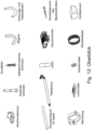
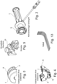
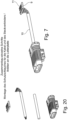
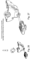
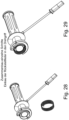
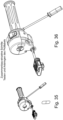
Figuren 9 bis 36 den Drehgriff (Handgasdrehgriff) nach der Erfindung in weiteren Details (ohne Bezugsziffern) sowie Schritte des Zusammenbaus und eine Übersicht der erforderlichen Elemente des Drehgriffes (Figur 12 ). In denFiguren 37 bis 42 ist ein Drehgriff nach dem Stand der Technik dargestellt. - In den
Figuren 1 bis 8 ist, soweit im Einzelnen dargestellt, mit der Bezugsziffer 1 ein Drehgriff bezeichnet, an den sich ein Gehäuse 2 anschließt, in dem eine Sensoranordnung eingebaut ist. Das Gehäuse 2 ist in ein Gehäuseoberteil 3 und ein Gehäuseunterteil 4 aufgeteilt, wobei das Gehäuseoberteil 3 und das Gehäuseunterteil 4 miteinander verschraubt werden können. - Wie insbesondere
Figur 2 zu entnehmen ist, ist das Rohr des Drehgriffes 1 verlängert und weist in der Nähe seines Endes ein Stützelement 5 auf, an dem ein Magnet 6 befestigt ist, der kreisbogenförmig ausgeführt ist. Das Gehäuse 2 mit Gehäuseoberteil 3 und Gehäuseunterteil 4 ist in Axialrichtung des Drehgriffes 1 in ein Gehäuseteil 7 und ein Zusatzgehäuseteil 8 unterteilt. In dem Gehäuseteil 7 ist das Stützelement 5 mit dem Magneten 6 und eine Leiterplatte 9, die mit dem Ende eines Kabelbaumes 10 verbunden ist, eingebaut. Die Leiterplatte 9 beinhaltet auch einen Sensor 11, wobei die Leiterplatte 9 so in das Gehäuseteil 7 eingebaut ist, dass der Sensor 11 mit dem Magneten 6 in Wirkverbindung steht. In dem Zusatzgehäuseteil 8 ist ein inFigur 5 dargestellte Schaltereinheit 12 eingebaut. Wie insbesondere den Figuren 3.4.6 und8 zu entnehmen ist, das Gehäuseteil 7 und das Zusatzgehäuseteil 8 durch eine Zwischenwand voneinander getrennt. - Das Gehäuseunterteil 4 weist eine Radialerweiterung 13 auf, in der Führungselemente 14 eingearbeitet sind. Die Führungselemente 14 dienen zur Führung der Leiterplatte 9 und zur Aufnahme eines Abschirmelements. Die Radialerweiterung reicht in axialer Richtung des Drehgriffes 1 gesehen zumindest bis zum Ende des Gehäuseteils 7 und weist eine axiale Öffnung 15 auf, die mittels eines Dichtelements verschlossen werden kann.
- Bezüglich weiterer Details und der Schritte des Zusammenbaus der beteiligten Elemente wird auf die übrigen zugehörigen Figuren verwiesen.
-
- 1
- Drehgriff
- 2
- Gehäuse
- 3
- Gehäuseoberteil
- 4
- Gehäuseunterteil
- 5
- Stützelement
- 6
- Magnet
- 7
- Gehäuseteil
- 8
- Zusatzgehäuseteil
- 9
- Leiterplatte
- 10
- Kabelbaum
- 11
- Sensor
- 12
- Schaltereinheit
- 13
- Radialerweiterung
- 14
- Führungselement
- 15
- Öffnung
Claims (5)
- Vorrichtung, aufweisend- ein Gehäuse (2),- einen röhrenförmigen Drehgriff (1),- ein Stützelement (5),- ein Gehäuseteil (7),- eine Leiterplatte (9),- ein Zusatzgehäuseteil (8),- eine Schaltereinheit (12),- ein Gehäuseoberteil (3),- ein Gehäuseunterteil (4) und- einen
Handgasdrehgriff mit einer in dem Gehäuse (2) gelagerten Sensoranordnung zur Erfassung der Drehbewegung des röhrenförmigen Drehgriffes (1), weiterhin mit einem Magneten (6), der mit dem Drehgriff (1) in Wirkverbindung steht, weiterhin mit einem gehäusefesten Sensor (11), ausgebildet zur Erfassung der Bewegung des Magneten (6), wobei der Sensor (11) mit einem Kabelbaum (10) der Vorrichtung in Verbindung steht, und mit einer Rückstellfeder, deren Federkraft der von Hand erzeugten Drehbewegung entgegen gerichtet ist, wobei der Magnet (6) an dem Stützelement (5) fixiert und das Stützelement (5) mit Abstand zum Drehgriff (1) angeordnet ist, wobei dem Magneten (6) bzw. dem Stützelement (5) das Gehäuseteil (7) zugeordnet ist und wobei dieses Gehäuseteil (7) auch zur Aufnahme des Sensors (11), der Leiterplatte: (9) und des Endes des Kabelbaumes (10) ausgebildet ist, wobei sich zwischen dem Gehäuseteil (7) und dem Ende des Drehgriffes (1) das Zusatzgehäuseteil (8) befindet, das zur Aufnahme der Schaltereinheit (12) ausgebildet ist, wobei weiterhin das Gehäuse (2) mit Gehäuseteil (7) und dem Zusatzgehäuseteil (8) parallel zur Drehachse des Drehgriffes (1) in das Gehäuseoberteil (3) und das Gehäuseunterteil (4) geteilt und aneinander befestigt sowie an dem Stützelement (5) gestützt sind. - Vorrichtung nach Anspruch 1, dadurch gekennzeichnet, dass der Sensor (11) auf der Leiterplatte (9) angeordnet ist.
- Vorrichtung nach einem der vorhergehenden Ansprüche, dadurch gekennzeichnet, dass das Gehäuseteil (7) und/oder das Zusatzgehäuseteil (8) im Bereich des Gehäuseunterteils (4) eine Radialerweiterung (13) mit einer axial zugänglichen Öffnung (15) aufweist.
- Vorrichtung nach einem der vorhergehenden Ansprüche, dadurch gekennzeichnet, dass die Radialerweiterung (13) Führungselemente (14) zur Aufnahme der Leiterplatte (9) und eines Abschirmelements aufweist.
- Vorrichtung nach einem der vorhergehenden Ansprüche, dadurch gekennzeichnet, dass die Öffnung (15) mittels eines Dichtelements verschließbar ist.
Applications Claiming Priority (2)
| Application Number | Priority Date | Filing Date | Title |
|---|---|---|---|
| DE102019133710 | 2019-12-10 | ||
| PCT/EP2020/085584 WO2021116313A1 (de) | 2019-12-10 | 2020-12-10 | E-gas mit integriertem schalterblock |
Publications (2)
| Publication Number | Publication Date |
|---|---|
| EP4072932A1 EP4072932A1 (de) | 2022-10-19 |
| EP4072932B1 true EP4072932B1 (de) | 2024-07-17 |
Family
ID=74105974
Family Applications (1)
| Application Number | Title | Priority Date | Filing Date |
|---|---|---|---|
| EP20833736.0A Active EP4072932B1 (de) | 2019-12-10 | 2020-12-10 | E-gas mit integriertem schalterblock |
Country Status (6)
| Country | Link |
|---|---|
| US (1) | US20230026992A1 (de) |
| EP (1) | EP4072932B1 (de) |
| CN (1) | CN114945506B (de) |
| DE (1) | DE102020132991A1 (de) |
| ES (1) | ES2987909T3 (de) |
| WO (1) | WO2021116313A1 (de) |
Families Citing this family (3)
| Publication number | Priority date | Publication date | Assignee | Title |
|---|---|---|---|---|
| DE102021110321A1 (de) * | 2021-04-22 | 2022-10-27 | Infineon Technologies Ag | Vorrichtungen und Verfahren zum Steuern der Leistung eines Fahrzeugmotors |
| CN117506283A (zh) * | 2023-11-16 | 2024-02-06 | 乐清市力诺机车部件有限公司 | 一种车把手组件装配设备及装配方法 |
| JP2026000714A (ja) * | 2024-06-18 | 2026-01-06 | 朝日電装株式会社 | スロットルグリップ装置 |
Citations (3)
| Publication number | Priority date | Publication date | Assignee | Title |
|---|---|---|---|---|
| WO2020178861A2 (en) * | 2019-03-07 | 2020-09-10 | Hero MotoCorp Limited | Multi-function throttle of vehicle |
| EP3747750A1 (de) * | 2019-06-04 | 2020-12-09 | Asahi Denso Co., Ltd. | Drosselgriffvorrichtung |
| EP3865386A1 (de) * | 2020-02-14 | 2021-08-18 | Toyo Denso Kabushiki Kaisha | Positionssensor und positionsdetektionsverfahren |
Family Cites Families (24)
| Publication number | Priority date | Publication date | Assignee | Title |
|---|---|---|---|---|
| DE202004021256U1 (de) * | 1990-03-14 | 2007-09-13 | Ab Elektronik Gmbh | Elektronisches Gassystem für Motorräder |
| US6377016B1 (en) * | 2001-01-23 | 2002-04-23 | Samuel Y. T. Strong | Handlebar accelerator for an electrical bicycle |
| US6750411B2 (en) * | 2002-11-06 | 2004-06-15 | Arctic Cat Inc. | Adjustable emergency stop switch |
| JP4371301B2 (ja) * | 2003-07-22 | 2009-11-25 | 朝日電装株式会社 | スロットル開度検出装置 |
| JP5060125B2 (ja) * | 2004-05-12 | 2012-10-31 | 株式会社ミクニ | アクセル操作装置 |
| JP4401926B2 (ja) * | 2004-10-14 | 2010-01-20 | ヤマハ発動機株式会社 | 相対位置検出制御装置及び鞍乗型車両 |
| ITTO20060526A1 (it) * | 2006-07-19 | 2008-01-20 | Bitron Spa | Dispositivo di comando a manopola, particolarmente per motoveicoli. |
| ITMI20080632A1 (it) * | 2008-04-10 | 2009-10-11 | Domino Spa | Dispositivo di comando del gas elettronico perfezionato per motocicli, motociclette, motoslitte e similari veicoli |
| EP2508840A4 (de) * | 2009-11-30 | 2016-08-10 | Nippon Seiki Co Ltd | Positionserkennungsvorrichtung |
| EP2507592B1 (de) * | 2009-12-04 | 2019-01-30 | Hirschmann Automotive GmbH | Handgasdrehgriff mit drehwinkel-messsystem |
| DE102010013686A1 (de) * | 2010-04-01 | 2011-10-06 | Gustav Magenwirth Gmbh & Co. Kg | Gasdrehgriff |
| JP2012047624A (ja) * | 2010-08-27 | 2012-03-08 | Nippon Seiki Co Ltd | 位置検出装置 |
| JP5618885B2 (ja) * | 2011-03-28 | 2014-11-05 | 株式会社ケーヒン | 車両のアクセル開度検出装置 |
| JP2013203177A (ja) * | 2012-03-28 | 2013-10-07 | Nippon Seiki Co Ltd | 位置検出装置 |
| ES2810775T3 (es) * | 2013-07-24 | 2021-03-09 | Nanjing Vmoto Co Ltd | Empuñadura de ajuste de velocidad de avance y retroceso para vehículo eléctrico y dispositivo de control de potencia de vehículo eléctrico |
| WO2016092564A2 (en) * | 2014-12-12 | 2016-06-16 | Varroc Engineering Pvt. Ltd. | Throttle position sensor |
| JP6253037B2 (ja) * | 2016-05-16 | 2017-12-27 | 本田技研工業株式会社 | グリップヒータの配線構造 |
| JP6655641B2 (ja) * | 2018-03-13 | 2020-02-26 | 本田技研工業株式会社 | 鞍乗り型車両のスロットル開度検出装置 |
| CN111712689A (zh) * | 2018-04-20 | 2020-09-25 | 海拉有限双合股份公司 | 手节气门传感器 |
| US10850795B2 (en) * | 2019-01-29 | 2020-12-01 | Asahi Denso Co., Ltd. | Throttle grip device |
| JP7507035B2 (ja) * | 2020-08-17 | 2024-06-27 | 東洋電装株式会社 | ハンドルスイッチ装置 |
| CN112009609B (zh) * | 2020-09-24 | 2025-08-01 | 宗申·比亚乔佛山摩托车企业有限公司 | 一种电动车油门转把 |
| US20230406442A1 (en) * | 2020-12-17 | 2023-12-21 | Dietmar MAEHR | Electronic motorcycle throttle with linear transmission |
| JP7750469B2 (ja) * | 2021-09-17 | 2025-10-07 | 朝日電装株式会社 | スロットルグリップ装置 |
-
2020
- 2020-12-10 US US17/783,555 patent/US20230026992A1/en not_active Abandoned
- 2020-12-10 DE DE102020132991.1A patent/DE102020132991A1/de active Pending
- 2020-12-10 EP EP20833736.0A patent/EP4072932B1/de active Active
- 2020-12-10 ES ES20833736T patent/ES2987909T3/es active Active
- 2020-12-10 CN CN202080092635.2A patent/CN114945506B/zh active Active
- 2020-12-10 WO PCT/EP2020/085584 patent/WO2021116313A1/de not_active Ceased
Patent Citations (3)
| Publication number | Priority date | Publication date | Assignee | Title |
|---|---|---|---|---|
| WO2020178861A2 (en) * | 2019-03-07 | 2020-09-10 | Hero MotoCorp Limited | Multi-function throttle of vehicle |
| EP3747750A1 (de) * | 2019-06-04 | 2020-12-09 | Asahi Denso Co., Ltd. | Drosselgriffvorrichtung |
| EP3865386A1 (de) * | 2020-02-14 | 2021-08-18 | Toyo Denso Kabushiki Kaisha | Positionssensor und positionsdetektionsverfahren |
Also Published As
| Publication number | Publication date |
|---|---|
| WO2021116313A1 (de) | 2021-06-17 |
| CN114945506A (zh) | 2022-08-26 |
| DE102020132991A1 (de) | 2021-08-05 |
| ES2987909T3 (es) | 2024-11-18 |
| CN114945506B (zh) | 2024-07-19 |
| EP4072932A1 (de) | 2022-10-19 |
| US20230026992A1 (en) | 2023-01-26 |
Similar Documents
| Publication | Publication Date | Title |
|---|---|---|
| EP4072932B1 (de) | E-gas mit integriertem schalterblock | |
| EP1743783B1 (de) | Spurfugenabdeckung bei Gelenkfahrzeugen | |
| EP3552938B1 (de) | Gabel-rahmen-einheit | |
| EP2176569A2 (de) | Elektronisches wählhebelmodul | |
| DE3421602A1 (de) | Schalt-lenkrad-anordnung fuer ein kraftfahrzeug | |
| DE8907647U1 (de) | Fahrerplatz für Traktoren | |
| DE102012110656B4 (de) | Stabilisatoranordnung für ein Fahrwerk eines Kraftfahrzeugs | |
| DE102004009927B4 (de) | Haltevorrichtung für eine Sattelstütze | |
| WO2007082835A1 (de) | Verfahren zur kontinuierlichen bestimmung der zugkraft f in einem seil einer feststellbremse | |
| DE9419696U1 (de) | Wägezellenanordnung | |
| EP3686612A1 (de) | Stromsensor mit verbesserter handhabbarkeit | |
| EP2188170B1 (de) | Unterbein für eine federgabel | |
| DE19857340C2 (de) | Kabelverschraubung für Kabel mit Abschirmummantelung | |
| DE102012016437B4 (de) | Schwingungsdämpfer für ein Kraftfahrzeug | |
| EP1949041B1 (de) | Beschleunigungssensor | |
| WO2019174781A1 (de) | Sensorvorrichtung zur erfassung einer drehstellung einer gelenkwelle von karosseriekinematikvorrichtungen, z.b. von spoilern | |
| DE202008003005U1 (de) | Pneumatische Steuerdose eines Abgasturboladers | |
| EP1764241B1 (de) | System, bestehend aus einer Luftfeder und einem Träger für die Luftfeder | |
| DE2748335C2 (de) | Klotzbremse | |
| DE102008040069A1 (de) | Werkzeugmaschine, insbesondere handgehaltene Stichsäge | |
| DE3619540C2 (de) | ||
| EP3864681A1 (de) | Stromwandlermodul für eine schaltanlage und entsprechende schaltanlage | |
| DE102018117713A1 (de) | Schwingungsdämpfer, Federbein, Fahrzeug und Verwendung | |
| DE102019200953A1 (de) | Bedienvorrichtung für ein vom menschen angetriebenes gefährt, insbesondere ein fahrrad, und eine bedieneinheit, welche die bedienvorrichtung aufweist | |
| DE19537288A1 (de) | Wägezelle |
Legal Events
| Date | Code | Title | Description |
|---|---|---|---|
| STAA | Information on the status of an ep patent application or granted ep patent |
Free format text: STATUS: UNKNOWN |
|
| STAA | Information on the status of an ep patent application or granted ep patent |
Free format text: STATUS: THE INTERNATIONAL PUBLICATION HAS BEEN MADE |
|
| PUAI | Public reference made under article 153(3) epc to a published international application that has entered the european phase |
Free format text: ORIGINAL CODE: 0009012 |
|
| STAA | Information on the status of an ep patent application or granted ep patent |
Free format text: STATUS: REQUEST FOR EXAMINATION WAS MADE |
|
| 17P | Request for examination filed |
Effective date: 20220608 |
|
| AK | Designated contracting states |
Kind code of ref document: A1 Designated state(s): AL AT BE BG CH CY CZ DE DK EE ES FI FR GB GR HR HU IE IS IT LI LT LU LV MC MK MT NL NO PL PT RO RS SE SI SK SM TR |
|
| DAV | Request for validation of the european patent (deleted) | ||
| DAX | Request for extension of the european patent (deleted) | ||
| STAA | Information on the status of an ep patent application or granted ep patent |
Free format text: STATUS: EXAMINATION IS IN PROGRESS |
|
| 17Q | First examination report despatched |
Effective date: 20230823 |
|
| GRAP | Despatch of communication of intention to grant a patent |
Free format text: ORIGINAL CODE: EPIDOSNIGR1 |
|
| STAA | Information on the status of an ep patent application or granted ep patent |
Free format text: STATUS: GRANT OF PATENT IS INTENDED |
|
| INTG | Intention to grant announced |
Effective date: 20240410 |
|
| GRAS | Grant fee paid |
Free format text: ORIGINAL CODE: EPIDOSNIGR3 |
|
| GRAA | (expected) grant |
Free format text: ORIGINAL CODE: 0009210 |
|
| STAA | Information on the status of an ep patent application or granted ep patent |
Free format text: STATUS: THE PATENT HAS BEEN GRANTED |
|
| AK | Designated contracting states |
Kind code of ref document: B1 Designated state(s): AL AT BE BG CH CY CZ DE DK EE ES FI FR GB GR HR HU IE IS IT LI LT LU LV MC MK MT NL NO PL PT RO RS SE SI SK SM TR |
|
| REG | Reference to a national code |
Ref country code: CH Ref legal event code: EP |
|
| REG | Reference to a national code |
Ref country code: DE Ref legal event code: R096 Ref document number: 502020008634 Country of ref document: DE |
|
| REG | Reference to a national code |
Ref country code: IE Ref legal event code: FG4D Free format text: LANGUAGE OF EP DOCUMENT: GERMAN |
|
| REG | Reference to a national code |
Ref country code: LT Ref legal event code: MG9D |
|
| REG | Reference to a national code |
Ref country code: ES Ref legal event code: FG2A Ref document number: 2987909 Country of ref document: ES Kind code of ref document: T3 Effective date: 20241118 |
|
| REG | Reference to a national code |
Ref country code: NL Ref legal event code: MP Effective date: 20240717 |
|
| PG25 | Lapsed in a contracting state [announced via postgrant information from national office to epo] |
Ref country code: PT Free format text: LAPSE BECAUSE OF FAILURE TO SUBMIT A TRANSLATION OF THE DESCRIPTION OR TO PAY THE FEE WITHIN THE PRESCRIBED TIME-LIMIT Effective date: 20241118 |
|
| PG25 | Lapsed in a contracting state [announced via postgrant information from national office to epo] |
Ref country code: NL Free format text: LAPSE BECAUSE OF FAILURE TO SUBMIT A TRANSLATION OF THE DESCRIPTION OR TO PAY THE FEE WITHIN THE PRESCRIBED TIME-LIMIT Effective date: 20240717 |
|
| PG25 | Lapsed in a contracting state [announced via postgrant information from national office to epo] |
Ref country code: PT Free format text: LAPSE BECAUSE OF FAILURE TO SUBMIT A TRANSLATION OF THE DESCRIPTION OR TO PAY THE FEE WITHIN THE PRESCRIBED TIME-LIMIT Effective date: 20241118 Ref country code: NL Free format text: LAPSE BECAUSE OF FAILURE TO SUBMIT A TRANSLATION OF THE DESCRIPTION OR TO PAY THE FEE WITHIN THE PRESCRIBED TIME-LIMIT Effective date: 20240717 |
|
| PG25 | Lapsed in a contracting state [announced via postgrant information from national office to epo] |
Ref country code: NO Free format text: LAPSE BECAUSE OF FAILURE TO SUBMIT A TRANSLATION OF THE DESCRIPTION OR TO PAY THE FEE WITHIN THE PRESCRIBED TIME-LIMIT Effective date: 20241017 |
|
| PG25 | Lapsed in a contracting state [announced via postgrant information from national office to epo] |
Ref country code: PL Free format text: LAPSE BECAUSE OF FAILURE TO SUBMIT A TRANSLATION OF THE DESCRIPTION OR TO PAY THE FEE WITHIN THE PRESCRIBED TIME-LIMIT Effective date: 20240717 Ref country code: GR Free format text: LAPSE BECAUSE OF FAILURE TO SUBMIT A TRANSLATION OF THE DESCRIPTION OR TO PAY THE FEE WITHIN THE PRESCRIBED TIME-LIMIT Effective date: 20241018 Ref country code: FI Free format text: LAPSE BECAUSE OF FAILURE TO SUBMIT A TRANSLATION OF THE DESCRIPTION OR TO PAY THE FEE WITHIN THE PRESCRIBED TIME-LIMIT Effective date: 20240717 |
|
| PG25 | Lapsed in a contracting state [announced via postgrant information from national office to epo] |
Ref country code: BG Free format text: LAPSE BECAUSE OF FAILURE TO SUBMIT A TRANSLATION OF THE DESCRIPTION OR TO PAY THE FEE WITHIN THE PRESCRIBED TIME-LIMIT Effective date: 20240717 |
|
| PG25 | Lapsed in a contracting state [announced via postgrant information from national office to epo] |
Ref country code: LV Free format text: LAPSE BECAUSE OF FAILURE TO SUBMIT A TRANSLATION OF THE DESCRIPTION OR TO PAY THE FEE WITHIN THE PRESCRIBED TIME-LIMIT Effective date: 20240717 |
|
| PG25 | Lapsed in a contracting state [announced via postgrant information from national office to epo] |
Ref country code: IS Free format text: LAPSE BECAUSE OF FAILURE TO SUBMIT A TRANSLATION OF THE DESCRIPTION OR TO PAY THE FEE WITHIN THE PRESCRIBED TIME-LIMIT Effective date: 20241117 |
|
| PG25 | Lapsed in a contracting state [announced via postgrant information from national office to epo] |
Ref country code: HR Free format text: LAPSE BECAUSE OF FAILURE TO SUBMIT A TRANSLATION OF THE DESCRIPTION OR TO PAY THE FEE WITHIN THE PRESCRIBED TIME-LIMIT Effective date: 20240717 |
|
| PG25 | Lapsed in a contracting state [announced via postgrant information from national office to epo] |
Ref country code: RS Free format text: LAPSE BECAUSE OF FAILURE TO SUBMIT A TRANSLATION OF THE DESCRIPTION OR TO PAY THE FEE WITHIN THE PRESCRIBED TIME-LIMIT Effective date: 20241017 |
|
| PG25 | Lapsed in a contracting state [announced via postgrant information from national office to epo] |
Ref country code: RS Free format text: LAPSE BECAUSE OF FAILURE TO SUBMIT A TRANSLATION OF THE DESCRIPTION OR TO PAY THE FEE WITHIN THE PRESCRIBED TIME-LIMIT Effective date: 20241017 Ref country code: PL Free format text: LAPSE BECAUSE OF FAILURE TO SUBMIT A TRANSLATION OF THE DESCRIPTION OR TO PAY THE FEE WITHIN THE PRESCRIBED TIME-LIMIT Effective date: 20240717 Ref country code: NO Free format text: LAPSE BECAUSE OF FAILURE TO SUBMIT A TRANSLATION OF THE DESCRIPTION OR TO PAY THE FEE WITHIN THE PRESCRIBED TIME-LIMIT Effective date: 20241017 Ref country code: LV Free format text: LAPSE BECAUSE OF FAILURE TO SUBMIT A TRANSLATION OF THE DESCRIPTION OR TO PAY THE FEE WITHIN THE PRESCRIBED TIME-LIMIT Effective date: 20240717 Ref country code: IS Free format text: LAPSE BECAUSE OF FAILURE TO SUBMIT A TRANSLATION OF THE DESCRIPTION OR TO PAY THE FEE WITHIN THE PRESCRIBED TIME-LIMIT Effective date: 20241117 Ref country code: HR Free format text: LAPSE BECAUSE OF FAILURE TO SUBMIT A TRANSLATION OF THE DESCRIPTION OR TO PAY THE FEE WITHIN THE PRESCRIBED TIME-LIMIT Effective date: 20240717 Ref country code: GR Free format text: LAPSE BECAUSE OF FAILURE TO SUBMIT A TRANSLATION OF THE DESCRIPTION OR TO PAY THE FEE WITHIN THE PRESCRIBED TIME-LIMIT Effective date: 20241018 Ref country code: FI Free format text: LAPSE BECAUSE OF FAILURE TO SUBMIT A TRANSLATION OF THE DESCRIPTION OR TO PAY THE FEE WITHIN THE PRESCRIBED TIME-LIMIT Effective date: 20240717 Ref country code: BG Free format text: LAPSE BECAUSE OF FAILURE TO SUBMIT A TRANSLATION OF THE DESCRIPTION OR TO PAY THE FEE WITHIN THE PRESCRIBED TIME-LIMIT Effective date: 20240717 |
|
| PG25 | Lapsed in a contracting state [announced via postgrant information from national office to epo] |
Ref country code: SM Free format text: LAPSE BECAUSE OF FAILURE TO SUBMIT A TRANSLATION OF THE DESCRIPTION OR TO PAY THE FEE WITHIN THE PRESCRIBED TIME-LIMIT Effective date: 20240717 Ref country code: DK Free format text: LAPSE BECAUSE OF FAILURE TO SUBMIT A TRANSLATION OF THE DESCRIPTION OR TO PAY THE FEE WITHIN THE PRESCRIBED TIME-LIMIT Effective date: 20240717 |
|
| REG | Reference to a national code |
Ref country code: DE Ref legal event code: R097 Ref document number: 502020008634 Country of ref document: DE |
|
| PG25 | Lapsed in a contracting state [announced via postgrant information from national office to epo] |
Ref country code: EE Free format text: LAPSE BECAUSE OF FAILURE TO SUBMIT A TRANSLATION OF THE DESCRIPTION OR TO PAY THE FEE WITHIN THE PRESCRIBED TIME-LIMIT Effective date: 20240717 |
|
| PG25 | Lapsed in a contracting state [announced via postgrant information from national office to epo] |
Ref country code: CZ Free format text: LAPSE BECAUSE OF FAILURE TO SUBMIT A TRANSLATION OF THE DESCRIPTION OR TO PAY THE FEE WITHIN THE PRESCRIBED TIME-LIMIT Effective date: 20240717 |
|
| PG25 | Lapsed in a contracting state [announced via postgrant information from national office to epo] |
Ref country code: SK Free format text: LAPSE BECAUSE OF FAILURE TO SUBMIT A TRANSLATION OF THE DESCRIPTION OR TO PAY THE FEE WITHIN THE PRESCRIBED TIME-LIMIT Effective date: 20240717 |
|
| PLBE | No opposition filed within time limit |
Free format text: ORIGINAL CODE: 0009261 |
|
| STAA | Information on the status of an ep patent application or granted ep patent |
Free format text: STATUS: NO OPPOSITION FILED WITHIN TIME LIMIT |
|
| 26N | No opposition filed |
Effective date: 20250422 |
|
| PG25 | Lapsed in a contracting state [announced via postgrant information from national office to epo] |
Ref country code: MC Free format text: LAPSE BECAUSE OF FAILURE TO SUBMIT A TRANSLATION OF THE DESCRIPTION OR TO PAY THE FEE WITHIN THE PRESCRIBED TIME-LIMIT Effective date: 20240717 |
|
| PG25 | Lapsed in a contracting state [announced via postgrant information from national office to epo] |
Ref country code: RO Free format text: LAPSE BECAUSE OF NON-PAYMENT OF DUE FEES Effective date: 20240717 |
|
| REG | Reference to a national code |
Ref country code: CH Ref legal event code: PL |
|
| PG25 | Lapsed in a contracting state [announced via postgrant information from national office to epo] |
Ref country code: LU Free format text: LAPSE BECAUSE OF NON-PAYMENT OF DUE FEES Effective date: 20241210 |
|
| GBPC | Gb: european patent ceased through non-payment of renewal fee |
Effective date: 20241210 |
|
| PG25 | Lapsed in a contracting state [announced via postgrant information from national office to epo] |
Ref country code: SE Free format text: LAPSE BECAUSE OF FAILURE TO SUBMIT A TRANSLATION OF THE DESCRIPTION OR TO PAY THE FEE WITHIN THE PRESCRIBED TIME-LIMIT Effective date: 20240717 |
|
| REG | Reference to a national code |
Ref country code: BE Ref legal event code: MM Effective date: 20241231 |
|
| PG25 | Lapsed in a contracting state [announced via postgrant information from national office to epo] |
Ref country code: BE Free format text: LAPSE BECAUSE OF NON-PAYMENT OF DUE FEES Effective date: 20241231 Ref country code: GB Free format text: LAPSE BECAUSE OF NON-PAYMENT OF DUE FEES Effective date: 20241210 |
|
| PG25 | Lapsed in a contracting state [announced via postgrant information from national office to epo] |
Ref country code: FR Free format text: LAPSE BECAUSE OF NON-PAYMENT OF DUE FEES Effective date: 20241231 |
|
| PG25 | Lapsed in a contracting state [announced via postgrant information from national office to epo] |
Ref country code: CH Free format text: LAPSE BECAUSE OF NON-PAYMENT OF DUE FEES Effective date: 20241231 |
|
| PG25 | Lapsed in a contracting state [announced via postgrant information from national office to epo] |
Ref country code: IE Free format text: LAPSE BECAUSE OF NON-PAYMENT OF DUE FEES Effective date: 20241210 |
|
| PGFP | Annual fee paid to national office [announced via postgrant information from national office to epo] |
Ref country code: DE Payment date: 20251211 Year of fee payment: 6 |
|
| PGFP | Annual fee paid to national office [announced via postgrant information from national office to epo] |
Ref country code: AT Payment date: 20260113 Year of fee payment: 5 |
|
| PG25 | Lapsed in a contracting state [announced via postgrant information from national office to epo] |
Ref country code: IT Free format text: LAPSE BECAUSE OF NON-PAYMENT OF DUE FEES Effective date: 20241210 |
|
| REG | Reference to a national code |
Ref country code: ES Ref legal event code: FD2A Effective date: 20260127 |
|
| PG25 | Lapsed in a contracting state [announced via postgrant information from national office to epo] |
Ref country code: ES Free format text: LAPSE BECAUSE OF NON-PAYMENT OF DUE FEES Effective date: 20241211 |