EP4072968B1 - Cartouche et procédé de fabrication d'une cartouche - Google Patents
Cartouche et procédé de fabrication d'une cartouche Download PDFInfo
- Publication number
- EP4072968B1 EP4072968B1 EP20812088.1A EP20812088A EP4072968B1 EP 4072968 B1 EP4072968 B1 EP 4072968B1 EP 20812088 A EP20812088 A EP 20812088A EP 4072968 B1 EP4072968 B1 EP 4072968B1
- Authority
- EP
- European Patent Office
- Prior art keywords
- cover
- insert
- cartridge
- predetermined breaking
- chamber
- Prior art date
- Legal status (The legal status is an assumption and is not a legal conclusion. Google has not performed a legal analysis and makes no representation as to the accuracy of the status listed.)
- Active
Links
Images



Classifications
-
- B—PERFORMING OPERATIONS; TRANSPORTING
- B65—CONVEYING; PACKING; STORING; HANDLING THIN OR FILAMENTARY MATERIAL
- B65D—CONTAINERS FOR STORAGE OR TRANSPORT OF ARTICLES OR MATERIALS, e.g. BAGS, BARRELS, BOTTLES, BOXES, CANS, CARTONS, CRATES, DRUMS, JARS, TANKS, HOPPERS, FORWARDING CONTAINERS; ACCESSORIES, CLOSURES, OR FITTINGS THEREFOR; PACKAGING ELEMENTS; PACKAGES
- B65D83/00—Containers or packages with special means for dispensing contents
- B65D83/771—Containers or packages with special means for dispensing contents for dispensing fluent contents by means of a flexible bag or a deformable membrane or diaphragm
Definitions
- the present invention relates to a cartridge for a squeezing device and a method for producing a cartridge.
- Cartridges are mainly used for storing materials such as glue, sealant, mortar, paint or lubricants.
- the material can also be easily applied to an object via the cartridges, provided the cartridge is inserted into a corresponding dispensing device.
- the dispensing device can be used to apply the material precisely. For example, a rod of the dispensing device presses against the base of the cartridge, which compresses the volume of the cartridge so that the material in the cartridge is pressed out of an opening.
- An attachment can be attached to the cartridge to enable the material to be applied to the object in a controlled and precise manner.
- Such a cartridge is, for example, from the DE 295 01 255 U1 known, wherein the cartridge comprises a foil bag, the ends of which are each closed with a clip, and a head part for receiving the foil bag.
- this cartridge has a piercing device with two piercing spades that pierce the foil bag in order to open it.
- closing the film bag with clips is disadvantageous because, depending on the type of material used, a certain amount of leakage is released to the outside. This happens due to capillary forces that push the enclosed material outwards through the clips, or due to excess pressure in the film bag that can arise at elevated temperatures.
- the opening process of the film bag is structurally complex and may lead to an undefined opening of the film bag.
- a film cartridge is known with a film tube that encloses at least one chamber in the circumferential direction.
- a cover separate from the film tube is provided, which closes off one axial end of the film tube.
- At least one first opening is formed in the cover for each chamber, through which the chamber can be filled with a filling material. After the chambers are completely filled, the first openings are closed with closures.
- the closures can be in the form of a film with a weakened zone.
- a cartridge for a squeezing device is proposed with at least one elongated film bag that is not inherently rigid and has a chamber for receiving a mass and a head part for interacting with the film bag, the film bag having an opening on a side facing the head part, which is closed by a cover, the cover having a predetermined breaking area.
- an inherently rigid insert is provided, which is connected to the film bag on the side facing the head part and has a passage, the cover being connected to the insert and closing the passage.
- the inherently rigid insert gives the film bag greater rigidity in the area of the cover, and the insert makes it easy to connect the cover to the rest of the film bag.
- One advantage of the invention is to provide an improved cover that is easy to handle.
- the cover securely closes the foil bag and prevents unwanted leakage of the mass in the chamber.
- the cover enables a simple and safe and particularly defined opening in order to be able to release the mass in the chamber.
- the predetermined breaking area improves the opening properties, particularly in the case of a cartridge used in a dispensing device.
- the predetermined breaking area in the cover means that the cartridge can be opened in a particularly defined manner in a dispensing device with comparatively low forces. At the same time, the cover can be easily made so stable that it is reliably prevented from opening itself, for example if it accidentally falls down. The cover also makes it easy to prevent leakage of the mass in the cartridge to a very small extent or completely, and is significantly reduced, especially in comparison to known cartridges.
- the cover is designed in particular as a film, but can alternatively also be designed in the form of a plate and can, for example, be a plastic plate.
- the predetermined breaking area can easily have any shape and, depending on the application, can be round, oval, square, rectangular, angular or linear, or a combination of these shapes.
- the chamber of the cartridge can be completely or exclusively enclosed by foil.
- an "inherently rigid component” is a component that retains its shape when removed from a device. Such a component is also referred to as inherently stable.
- the cover in the predetermined breaking area has a defined material discontinuity at least in some areas, in particular in an entire flat area, than in a further area of the cover.
- the cover is structurally simple and can be manufactured inexpensively, whereby a safe and defined opening of the cover in the predetermined breaking area is possible.
- the defined material discontinuity can be formed, for example, by the cover in the predetermined breaking area having an increased or reduced material thickness at least in some areas than in a further area of the cover. This enables a safe and defined opening of the cover in the predetermined breaking area.
- Such a cover is also simple and inexpensive to manufacture.
- the predetermined breaking area of the cover can also have a different material strength than another area of the cover. This also enables the cover to be opened safely and in a defined manner in the predetermined breaking area.
- a further area of the cover is understood here to be an area of the cover that is not assigned to the predetermined breaking area and extends outside the defined predetermined breaking area.
- material properties are preferably essentially constant.
- the predetermined breaking area of the cover is limited by a linear material weakening.
- the linear material weakening encompasses the predetermined breaking area in particular completely and thus separates the predetermined breaking area from the further area of the cover.
- the linear material weakening can be either a continuous, in particular uniform, material weakening or a perforation, whereby the material thickness or the material strength of the linear material weakening can be both lower and higher than the material thickness of the wider area of the cover.
- an advantageous embodiment of the invention provides that the predetermined breaking area of the cover has a defined different material strength than another area of the cover. It can be provided that in the entire predetermined breaking area or in an area linearly surrounding the predetermined breaking area, a different strength or a different structure is provided than in the other area of the cover. This can be achieved, for example, by the effect of temperature, in particular by means of a laser or energetic radiation.
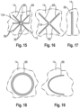
- the predetermined breaking area of the cover can preferably have a notch that is star-shaped, cross-shaped, line-like, circular, semi-circular or the like.
- the special geometry of the notch enables the pressure required to open the cartridge to be adjusted.
- the opening characteristics can be influenced by the shape and spatial arrangement of the notch.
- the insert is conical on a side facing the head part. This makes it possible to provide a cartridge in a structurally simple manner in which a cover connected to the insert can be easily and securely attached to the insert under all conditions and is held securely to the insert. Furthermore, undesirable peeling or shearing and/or damage to the cover, which is designed as a film, for example, is reliably prevented due to the favorable introduction of force.
- the conical design of the insert means that in the event of a pressure increase in the chamber before opening, the notch effect in the connection area of the cover to the insert is low and the cover is reliably opened in the area of the predetermined breaking point when the cover or the film expands due to pressure being applied during a pressing process.
- a surface of the insert facing the head part forms an angle of between 10° and 50° with a horizontal line arranged perpendicular to a central axis of the film bag, with a region of the surface facing the central axis being at a greater distance from a base part of the film bag than a region of the surface facing away from the central axis.
- the angle particularly preferably has a value of between 15° and 35°, in particular approximately 25°.
- the insert can have at least one vent opening that is independent of the passage and/or at least one vent slot that is independent of the passage.
- the passage is in particular circular and, when the film bag is filled, is preferably at least approximately tightly against a filling tube of a filling device. Air in the chamber of the film bag can easily escape through the vent opening and/or the vent slot. After the filling process, the vent opening and/or the vent slot can be closed by the cover, in particular in a sealing manner, so that the mass in the chamber is sealed.
- the passage of the insert can have at least one venting notch in a region facing the central axis of the film bag, so that during a filling process of the film bag with a filling device having a filling tube with a circular cross-section, air in the chamber of the film bag can escape through the venting notches directly along the filling tube.
- vent opening or vent slot prevents the occurrence of high pressures during a filling process, which makes the filling process cost-effective.
- a plurality of ventilation openings and/or ventilation slots are provided, which are arranged on the insert in particular evenly distributed around the circumference.
- the ventilation openings have a substantially circular cross-section.
- the ventilation slots are preferably arranged substantially concentrically to a central axis of the insert.
- the vent notches may have a substantially rectangular, triangular, curved or similar shape.
- the insert and the head part have a cooperating and essentially opposite contour in areas facing each other, wherein the cover arranged in the area of the contours is designed to be weldable.
- the cover can preferably not only be connected to the insert in a welding process, but the insert can alternatively or additionally also be connected to the head part by means of the cover by means of a welding process.
- a welding tool provided for this purpose preferably has a the film bag has a cylindrical recess that essentially corresponds to it and can be guided around the film bag in the direction of the insert from a side facing away from the head part, the welding tool being designed to heat the cover at least in the area of the contours of the insert and the head part in such a way that the insert can be welded to the head part by means of the cover.
- the welding tool preferably surrounds the respective film bag on the outside.
- the film bag can preferably be formed by a cylindrical film tube which is closed at the bottom by a base part, wherein the base part is in particular glued and/or welded to the film tube.
- the film tube also called tubular film or blown film, can be formed from a thermoplastic material, wherein the film tube can be extruded or welded or glued at its longitudinal seam. Since the base part is in particular glued and/or welded, a material-locking connection is created, which improves the storage properties of the cartridge, so that the leakage rate of the cartridge is reduced compared to a cartridge in which a film bag is closed by a clip closure.
- the cartridge has, for example, a head part which comprises at least one receptacle for at least one insert.
- the head part represents a type of adapter, as the head part enables commercially available attachments or standardized squeezing devices to be used to apply the mass in the cartridge.
- the insert which partially protrudes beyond the foil bag, thus represents an interface to the head part.
- the insert has a stepped elevation on the side that protrudes from the foil bag, via which the insert is held in the head part holder.
- the elevation enables the insert to be held securely in the head part holder. This also improves the tightness during operation.
- the cover can also rest on at least two surfaces of the stepped elevation, which are essentially perpendicular to one another, for example. This means that the cover can also be securely attached to the insert on the underside and to the head part's receptacle on the top. This also reduces leakage.
- the head part has an outlet nozzle that is in fluid communication with the receptacle.
- the outlet nozzle can define the flow rate, in particular via its diameter.
- the outlet nozzle can be provided with a thread.
- the thread allows commercially available attachments or squeezing devices for applying the compound in the cartridge to be attached precisely to an outlet opening of the outlet nozzle, enabling precise positioning and dosing of the compound during application.
- the outlet nozzle can also have a partition that divides the volume into two or more outlet channels.
- the relative position of the partition in the outlet nozzle defines the cross-sections of the outlet channels and thus the flow rates through these outlet channels.
- the outlet channels can have different diameters.
- the outlet channels can be oriented coaxially to each other.
- the head part can therefore be suitable for holding several film bags that may have different masses.
- the head part separates the different masses up to the outlet opening, so that the different masses can only come into contact after the outlet opening. This is important for two-component adhesives, for example.
- the cartridge can therefore hold different masses and serve as a multi-component packaging.
- the different diameters of the outlet openings make it possible to set a specific mixing ratio of the different masses.
- the masses contained in the cartridge can be a chemical mass or a liquid, for example components of a two-component mixture.
- sealants multi-component mortars, multi-component coating compounds, multi-component paints, multi-component foam precursors, multi-component adhesives, multi-component sealants and multi-component lubricants can be stored in the corresponding cartridges.
- the head part can be assigned a spreading space into which the cover can spread.
- the spreading space enables the cover to be opened in a controlled manner so that it does not impede the flow of the escaping mass. On the one hand, this results in a laminar flow, as there are no obstacles in the flow path that could result in turbulent flow. On the other hand, it ensures that the flow rate is precisely maintained, which is important for the mixing ratio of two or more components.
- the passage is tapered. This means that the passage acts like a confuser or nozzle when the mass flows out.
- the tapered passage can also act as a diffuser when filling the film bag.
- the passage can be adapted in particular to a filling cone of the mass in the chamber. This enables the chamber to be filled optimally with a mass so that little to no air remains in the chamber.
- the cartridge has at least one second, non-rigid, elongated foil bag with a chamber for holding a mass.
- the cartridge can thus be used as a multi-component packaging.
- a resin for example an epoxy resin
- a hardener for a two-component adhesive can be stored in the same packaging.
- the second foil bag can have the same length as the first foil bag, in which case a ratio of the base areas of the foil bags determines the mixing ratio to be achieved.
- a ratio of the base areas of the foil bags determines the mixing ratio to be achieved.
- two foil bags are used which have a different length from one another.
- the base part can be made of a plastic, such as polyethylene (PE), polypropylene (PP), polyethylene terephthalate (PET), polybutylene terephthalate (PBT), and/or acrylonitrile-butadiene-styrene copolymer (ABS).
- the base part can be manufactured by injection molding, 3D printing or machining. It can also consist of a preformed mono- or multi-layer film.
- the base part can be made of the same or a comparable material as the cover. This enables the base part to be manufactured cost-effectively.
- the film bag can comprise a mono- or multi-layer film.
- the total layer thickness is 50 to 350 ⁇ m, in particular 80 to 150 ⁇ m.
- the materials used can be PE, PP, PET, aluminum, ethylene-vinyl alcohol copolymer (EVOH), polyamide (PA), and/or polylactide (PLA). Each layer can also be coated with silicon oxide or aluminum oxide.
- the multi-layer film can be produced by adhesive or extrusion lamination.
- the foil bag should preferably be able to be folded evenly during a pressing process, similar to an accordion, so that as much of the mass in the chamber as possible can be used. During use, the foil bag is exposed to chemical masses or liquids that can sometimes attack the foil bag. An exact composition The film bag must therefore sometimes be adapted to the mass or liquid contained in the chamber, in particular to the corresponding material properties.
- the cover can preferably be designed as a multi-layer film.
- the cover has a PE and/or a PP layer on the top and bottom so that it can be welded, for example thermally welded, to other plastic parts of the cartridge.
- the film can also have layers of PVC, especially if other plastic parts of the cartridge are made of PVC.
- a barrier layer can be provided between a top and a bottom of the cover, which prevents, for example, the penetration of oxygen or water vapor into the chamber after it has been closed by the cover. This can also reliably prevent the mass in the chamber from emitting gases.
- the total thickness of the cover can be between 50 ⁇ m and 350 ⁇ m. In particular, it is intended that the total thickness is between 130 ⁇ m and 250 ⁇ m.
- the barrier layer may comprise, for example, aluminum or coatings of silicon oxide and/or aluminum oxide on PET, bi-axially arranged PP (BOPP), PA, PLA, or ethylene-vinyl alcohol copolymer (EVOH).
- BOPP bi-axially arranged PP
- PA PA
- PLA PLA
- EVOH ethylene-vinyl alcohol copolymer
- multilayer films are preferred.
- the technical advantages described for the cartridge apply analogously to the proposed method for producing the cartridge.
- the production of the filled cartridge can be separated into different production steps.
- the production of the foil bag is separated from the filling of the foil bag and the attachment of the foil bag in the head part.
- the modular design of the cartridge allows the individual elements to be adapted to different requirements of the cartridge, which are imposed by the mass in the chamber.
- the decoupling of the production of the film bag from the filling reduces the complexity of the cartridge production. This ensures better quality, as different machines and materials can be used for production and filling.
- the predetermined breaking area of the cover can be created, for example, before the film bag is produced, after the film bag is produced, or during the film bag is produced.
- the predetermined breaking area is preferably only introduced into the cover after the mass has been filled into the chamber and the chamber has been closed with the cover. In this respect, material of the cover is removed, for example, from an outside side facing away from the chamber in order to form the predetermined breaking area.
- the predetermined breaking area can also be created before the cover is attached to the chamber. This also makes it possible to form the predetermined breaking area on an underside of the cover facing the chamber, or to form two opposing predetermined breaking areas on the bottom and top.
- the film bag has a film tube and a base part, wherein the film tube is preferably formed by welding or gluing.
- the base part and a dimensionally stable insert are connected to the film tube, so that a film bag is created which comprises a chamber which is delimited by the film bag, the insert and the base part, wherein the insert has a passage.
- the base part can be designed, for example, with a film or with a dimensionally stable material.
- the predetermined breaking area of the cover is produced by means of a laser, a material weakening by hot stamping or by thermal stamping with a heated stamp, by scoring with a suitable cutting tool or knife or during a welding process of the cover to the insert.
- At least one welding parameter is varied in comparison to the connection of the cover to the insert in other areas to achieve the predetermined breaking area and, for example, a higher pressure, an increased temperature or an extended welding time or a combination of these parameters is used.
- the predetermined breaking area is created in the immediate vicinity of the weld seam or in the weld seam itself.
- the insert has at least one material extension, in particular a material extension surrounding the passage, which melts during the closing of the passage.
- the tightness is thereby improved, since a material-locking connection of the insert to the cover can be ensured due to the melt.
- the material extension can surround the passage of the insert. It acts as the intended melting point of the insert, so that a high-quality cover is provided and no mass can escape from the chamber through the opening.
- the insert can have at least one vent notch, a vent opening and/or a vent slot through which air can escape during filling.
- a head part which has at least one receptacle and the insert is inserted into the receptacle.
- the head part allows the cartridge to be inserted into commercially available squeezing devices, which allows the cartridge to be squeezed out in a controlled manner when the mass in the chamber is applied to a corresponding object.
- a second film bag with a chamber is provided.
- the second film bag can be designed in a similar way to the first film bag and can be connected to the head part.
- the connection is preferably made by means of gluing or welding. Accordingly, a multi-component packaging or cartridge can be produced in a simple manner.
- the covers of the various chambers can be designed with different predetermined breaking areas, for example different notches.
- Figure 1 shows a cartridge 10 in an exploded view in a longitudinal section.
- the cartridge 10 comprises a head part 12, two covers 14, two inserts 16 and two foil bags 18.
- the film bags 18 are not inherently rigid and each have a cylindrical and essentially elongated shape.
- the film bags 18 each delimit a chamber 20 and have an opening 22, wherein the chamber 20 can be closed in particular in a sealing manner by the film bags 18.
- the film bag 18 is formed by a base part 24 and a film tube 26.
- the base part 24 has a base surface 28 and a collar 30 running around the base surface 28.
- the film tube 26 is attached to the collar 30 on the outside by welding or gluing. In principle, the film tube 26 can also be attached to the collar 30 on the inside by welding or gluing.
- the film tube 26 can be made, for example, from a film by gluing or welding edge areas. It can also be provided to use a prefabricated film tube or a prefabricated film bag.
- the base area 28 is, for example, circular, so that the chamber 20 is cylindrical. In principle, however, any shape of the base area 28 is conceivable, for example rectangular or polygonal.
- the insert 16 is designed to be inherently rigid and is inserted at least partially into the corresponding chamber 20 of an associated film bag 18 through the opening 22.
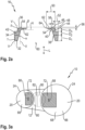
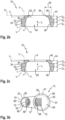
- Fig. 2a , Fig. 2b and Fig. 2c show different design variants of an insert 16 or a cover 14, wherein the inserts 16 are each provided for connection to a film bag 18.
- the insert 16 according to Fig. 2a has three sections 32, 34 and 36 in one piece, which are arranged one on top of the other with respect to a longitudinal direction L of the film bag 18 or the cartridge 10, i.e. they each adjoin one another.
- the first section 32 is arranged on a side facing away from the head part 12 and the third section 36 is arranged on a side facing the head part 12.
- the first section 32 has, for example, a thickness D1 in the longitudinal direction L of in particular less than 4 mm
- the second section 34 has a thickness D2 in the longitudinal direction L of in particular less than 5 mm
- the third section 36 has a thickness D3 in the longitudinal direction L of in particular less than 5 mm.
- the chamber tapers in the direction of the head part 12.
- the inner side 38 of the third section 36 has, on a side facing the head part 12 above the bend 40, a second region which has an angle ⁇ with respect to a horizontal H arranged perpendicular to the longitudinal axis L.
- the angle ⁇ can have a value between 0° and 60°.
- the insert 16 has an outer side 42 facing away from the chamber 20.
- the outer side 42 in the region of the third section 36 comprises two surfaces 44 and 46.
- the surface 46 is arranged in longitudinal section parallel to the horizontal H and thus to the base surface 28, whereas the surface 44 in longitudinal section has an angle ⁇ with respect to the vertical or the longitudinal direction, but in an alternative embodiment can also be arranged substantially parallel to the vertical V.
- the surfaces 44 and 46 may be arranged substantially perpendicular to each other in the longitudinal section.
- Fig. 2b shows a further embodiment of the insert 16, which differs from the insert 16 according to Fig. 2a essentially differs in that the third section 36 has a conical region which encompasses the surface 46 and faces the head part 12.
- the surface 46 facing the head part 12 forms an angle ⁇ of 10-50° with the horizontal H, particularly preferably of approximately 15° - 35°.
- the surfaces 44 and 46 are not arranged perpendicular to one another in the longitudinal section and here form an obtuse angle.
- the radially outer surface 42 in the region of the third section 36 is arranged essentially in the longitudinal direction L.
- the insert 16 shown essentially corresponds to the insert 16 according to Fig. 2b , wherein the cover 14 in the embodiment shown is designed as a plastic plate.
- the third section 36 of the inserts 16 according to Fig. 2a and 2b is set back with respect to the outer side 42 compared to the second section 34, the third section 36 having a smaller outer diameter than the second section 34. This forms a stepped elevation 48 of the insert 16.
- the third section 36 has a width 50 of 3 to 8 mm in the direction of the horizontal H and is offset inwardly by a radial offset 52 of 2 to 4 mm relative to the second section 34.
- a material extension 54 is provided which projects essentially perpendicularly from the surface 46 parallel to the horizontal H, i.e. in the longitudinal direction L.
- the material extension 54 has a predefined height 56, as will be explained below, and a width 58 of in particular less than 2 mm.
- the outer side 42 in the region of the first section 32 has an angle ⁇ of between 0 and 10° with respect to the vertical V and the outer side 42 in the region of the third section 36 encloses an angle ⁇ of between 0 and 60° with the longitudinal direction L.
- the inner side 38 of the sections 32, 34, 36 facing the chamber 20 encloses a passage 60 which tapers conically from the first section 32 towards the third section 36.
- the passage 60 in the area of the first section 32 has a larger opening 61 compared to the opening 63 in the area of the third section 36.
- the insert 16 has a plurality of holes 62 in the third section 36, which are arranged between the material extension 54 and a radially inward-pointing tip 64 of the third section 36 and here extend essentially in the longitudinal direction L.
- the insert 16 is ring-shaped so that it can be coupled with the cylindrical film tube 26.
- the inside of the film tube 26 is connected to the insert 16, wherein the film tube 26 is connected to the outside 42 in the region of the first section 32.
- the film tube 26 is welded or glued to the insert 16.
- the cover 14 is provided, as can be seen from Fig. 1 In the assembled state of the cartridge 10, the cover 14 rests in radially outer regions on the stepped elevation 48 essentially on the two surfaces 44 and 46.
- the cover 14 is connected to the insert 16, for example by welding or gluing, and closes the passage 60 and the holes 62. Accordingly, the Cover 14 the chamber 20, so that the chamber 20 is preferably completely sealed when the cover 14 is assembled.
- the head part 12 has two receptacles 66 which, when assembled, interact with the inserts 16 and the cover 14.
- the receptacle 66 is divided into two areas, as can also be seen from the Fig. 3a can be seen.
- the receptacle 66 is adapted to the insert 16 and the stepped elevation 48, so that the insert 16, as shown in Fig. 1 can be seen, with the cover 14 rests against a side surface 70 of the receptacle 66, i.e. over its radially outward facing outer side 42, in particular in the region of the third section 36, and, as in Fig. 3a as can be seen, rests on the support area 68, with the cover 14 in between.
- the receptacle 66 comprises an expansion region 72, which is designed as a recess in the receptacle 66 and, as in Fig. 1 As can be seen, it forms a propagation space 74, the function of which will be explained later.
- the head part 12 further comprises an outlet nozzle 76 with an outlet opening 78 and an outlet channel 80.
- the outlet opening 78 is in fluid communication with the expansion space 74 and the receptacle 66 through the outlet channel 80.
- the outlet nozzle 76 shown has two outlet channels 80 which are in fluid communication with the respective receptacle 66 and are separated from one another by a partition 82 which extends from a connecting web 84 separating the receptacles 66 to the outlet opening 78.
- the two outlet channels 80 as in Fig. 1 and Fig. 3a shown, have a different cross-section, in particular a different diameter, in order to adjust a mixing ratio of the masses, as explained below.
- the outlet nozzle 76 also has a thread 86, through which an attachment (not shown) can be attached to the outlet opening 78 of the head part 12.
- This attachment can be part of a squeezing device into which the cartridge 10 can be inserted or placed.
- the cover 14 comprises a predetermined breaking area 88 which is arranged in the area of the expansion area 72 of the receptacle 66 when the cartridge 10 is connected to the head part 12.
- the cover 14 has a lower material thickness or material strength in the predetermined breaking area 88 than in other areas of the cover.
- the lower The cover 14 is weakened in the predetermined breaking area 88 according to the material thickness.
- the predetermined breaking area 88 can be created, for example, by a laser or by a heated stamp in the cover 14.
- the predetermined breaking area 88 can be created, for example, after the cover 14 has been arranged on the insert 16, preferably from a side facing away from the chamber 20.
- the predetermined breaking area 88 can also be created from a side of the cover 14 facing the chamber 20.
- areas opposite one another can be machined on both sides of the cover 14 so that the predetermined breaking area 88 extends on both sides of the cover 14.
- the predetermined breaking area 88 can also be created by deforming material using a stamp or by melting material using a stamp.
- material in the predetermined breaking area 88 is vaporized using a laser, in particular on a side facing away from the chamber 20, so that the predetermined breaking area 88 represents, for example, a notch in the cover 14 that is visible from the outside. If the predetermined breaking area 88 is produced by hot stamping, the predetermined breaking area 88 is also visible from an outside. The predetermined breaking area 88 can also be produced by scoring. The predetermined breaking area 88 can also be produced before the cover 14 is attached to the insert 16 by the methods mentioned.
- Fig. 3b shows a similar view as Fig. 3a , whereby only the differences are discussed below.
- the predetermined breaking area 88 is arranged in an area of the expansion area 72 which faces the other foil bag 18.
- a circumferential weld seam 89 is shown, by means of which the cover 14 is fixed to the surface 46 of the insert 16.
- the weld seam 89 is limited in simplified form by two circles 91, 93, shown here in dashed lines, which run essentially concentrically to a longitudinal axis of the film bag 18, the weld seam 89 here representing a partial area of the surface 46.
- the predetermined breaking area 88 in the present case represents, for example, a section of the weld seam 89, the predetermined breaking area 88 being at least partially, in particular completely, congruent with the weld seam 89.
- the predetermined breaking area 88 can also be located in the immediate vicinity of the weld seam 89.
- the predetermined breaking area 88 is created during the production of the weld seam 89 by varying the welding parameters.
- the predetermined breaking area 88 is a targeted weakening of the cover 14, so that when the film bag 18 or the chamber 20 is squeezed out by a squeezing device, the cover 14 tears open in the predetermined breaking area 88 or opens there in a defined manner.
- the base part 24 of the chamber 20 is pressed in the direction of the head part 12, for example by means of a stamp of a squeezing device.
- the cover 14 then expands into the expansion region 72.
- the predetermined breaking region 88 of the cover 14 is assigned to the expansion region 72, wherein the predetermined breaking region 88 breaks open above a certain force or a corresponding pressure, so that the mass can flow through the passage 60 of the insert 16 and the torn predetermined breaking region 88 from the chamber 20 into the outlet channel 80.
- the mass can thus flow out of the head part 12 through the outlet opening 78 and be applied to an object, for example.
- the outlet channel 80 and the expansion space 74 should be kept as small as possible.
- the expansion region 72 which is assigned to the chamber 20, has an area of 1 - 40% based on the total area of the respective receptacle 66 or 68, better 2 - 35% and preferably 3 - 30%.
- the expansion height 90 of the expansion space 74 should be between 2.0 and 15.0 mm, in particular 3.0 and 12.0 mm and preferably 5.0 and 10.0 mm.
- the opening force required to break open the predetermined breaking area 88 can be adjusted by changing the expansion area 72. Furthermore, it is also possible to adjust the opening force by appropriately arranging the predetermined breaking area 88 on the cover 14 or by adjusting the shape and size of the predetermined breaking area 88.
- the required opening force is increased if the predetermined breaking area 88 is displaced from a central area to an edge area of the expansion surface 72.
- the expansion area 72 and the predetermined breaking area 88 are selected such that the two chambers 20 break open essentially at an identical opening force, so that the masses can flow out of the chambers 20 synchronously. Accordingly, a predetermined Mixing ratio of the masses from the two chambers 20 can be realized, which is predetermined by an area ratio of the base areas 28 or the division of the outlet channel 80 by the partition wall 82.
- Fig. 4 shows a schematic comparison between the chamber 20 of the cartridge 10, which is in the upper half of the Fig. 4 and a chamber 92 of a cartridge 94 known from the prior art, which is arranged in the lower half of the figure, in a longitudinal section.
- the left side of the Fig. 4 shows the cartridges 10, 94 in a filled state and the right side of the Fig. 4 the cartridges 10, 94 in a squeezed or emptied state.
- the cartridges 10, 94 in the present example are enclosed by a cuboid 96 of the same volume, which is shown with dashed lines.
- a width B, a length L and a height (not shown) of the two cuboids 96 are essentially the same here.
- the chamber 92 of the cartridge 94 from the prior art is closed on both sides by clips 98.
- the clips 98 result in the chamber 92 being spherically closed at each end, so that the chamber 92 has a smaller volume than the cuboid 96 according to the cartridge 10 according to the invention. Accordingly, more mass can be filled into the chamber 20 than into the chamber 92.
- the chamber 20 of the pressed-out cartridge 10 is enclosed by a cuboid 100.
- the cuboid 100 is smaller than the cuboid that encloses the pressed-out chamber 92 from the prior art, so that the pressed-out chamber 20 has a smaller volume than the pressed-out chamber 92 of the prior art. Accordingly, with the same available initial volume according to cuboid 96, the cartridge 10 can hold more mass than the cartridge 94 known from the prior art, and less mass remains in the cartridge 10 after squeezing compared to the cartridge 94 from the prior art.
- the cartridge 10 in Figure 5 only one chamber 20, so that only one insert 16, one cover 14, one receptacle 66 and one outlet channel 80 are present. Accordingly, no partition 82 is provided which divides the outlet channel 80 into sub-channels.
- a film tube 26 is then attached to the outside of the collar 30 on the circumference or around the base part 24, for example by gluing or welding, so that a film bag 18 is created which has an opening 22.
- the film tube 26 can also be attached to the inside of the collar 30.
- the inside of the opening 22 is then attached to the outside 42 of the insert 16 in the region of the first section by welding and/or gluing.
- the chamber 20 is filled with a mass 102 through a filling device 104 which has a filling head 106 and a filling tube 108.
- the filling head 106 and the filling tube 108 are in fluid communication with one another.
- the filling head 106 is, for example, connected to a reservoir of the mass 102 and pumps the mass 102 from the reservoir into the filling head 106.
- the filling tube 108 projects through the opening 63 and the passage 60 of the insert 16 into the chamber 20, so that the mass 102 can be introduced from the filling head 106 through the filling tube 108 into the chamber 20.
- the air in the chamber 20 can escape through the holes 62, so that the filling tube 108 can have the same cross-section as the opening 63 of the third section 36 of the insert 16.
- the mass 102 can thus be introduced into the chamber 20 through a large opening, so that little pressure is required for the filling process.
- the geometry of the insert 16 is adapted to a filling cone 110 of the chemical mass 102.
- the geometry is adapted in particular to the filling cone 110 of viscous chemical mortar. This ensures that relatively little and in particular no air is present between the insert 16 and the chemical mass 102 after the filling process. This is advantageous because the presence of air can reduce the durability of the mass 102 and, in the case of larger air bubbles, can have an undesirable effect on the mixing ratio achieved when using two foil bags 18.
- a material extension 54 can be provided which is designed to be circumferential and connected to the third section 36 of the insert 16 and which can be designed in a ring shape.
- Several separate material extensions 54 can also be provided which are designed, for example, in a partially ring shape and each extend only over a partial area of the circumference of the insert 16.
- the at least one material extension 54 serves as a melting point so that the cover 14 and the insert 16 can be connected to one another in one piece, in particular in a materially bonded manner, by melting the material extension 54.
- cover 14 is also attached to the surfaces 44 and 46 of the insert 16.
- the molten material of the material extension 54 flows along the surfaces 44, 46 to form a kind of adhesive layer for the cover 14.
- the cover 14 can be designed as a monofilm. After the insert 16 is closed, a part of the cover 14 is removed from the top of the cover 14, so that a predetermined breaking area 88 is created. This takes place, for example, when the chamber 20 is closed, by removing material from the cover 14 from the outside.
- the predetermined breaking area 88 can be formed by a defined setting of the welding parameters in a predefined area. For example, a higher pressure, an increased temperature or an extended welding time or a combination of these parameters can be provided in order to produce the predetermined breaking area 88 during the welding process of the cover 14 to the insert 16.
- the predetermined breaking area 88 can be produced in a simple manner in the immediate vicinity or in the surface 46.
- the head part 12 is provided and the insert 16 with the cover 14 is fastened in the receptacle 66.
- the surface 44 of the stepped elevation 48 rests against the side surface 70 of the receptacle 66.
- This method step can be carried out, for example, by gluing or welding or a similar fastening method.
- Fig. 7 shows in the upper area the insert 16 in a longitudinal section and in a lower area a corresponding top view of the insert 16.
- the holes 62 are arranged as ventilation openings 112 around the circumference of the opening 63 and have a diameter 114 of in particular less than 3 mm.
- the insert 16 has eight ventilation openings 112. In principle, any number of ventilation openings 112 can be provided.
- the ventilation openings 112 can be designed as ventilation holes.
- the top view of the insert 16 according to Figure 8 shows that the holes 62 are designed as ventilation slots 116 which are arranged circumferentially around the opening 63, in particular at regular intervals from one another and/or coaxially to the central axis of the opening 63.
- Fig. 9 shows a detailed view of one of the ventilation slots 116 from Fig. 8
- a width 118 of the ventilation slot 116 in the radial direction is in particular less than 3 mm and a length 120 in the circumferential direction is, for example, 1 to 20 mm.
- the holes 62 can also be designed as vent notches 122.
- the vent notches 122 function as an enlargement of the opening 63, the original shape of which is shown in dashed lines in the area of the vent notches 122.
- FIG. 11 A detailed view of a vent notch 122 is shown in Fig. 11 from which it can be seen that a width 124 of the vent notch 122 in the circumferential direction has a value in particular less than 4 mm.
- Fig. 7a, Fig. 7b and Fig. 7c show further possible designs of inserts 16 for venting the film bag 18 during a filling process.
- a radially inner contour 123 of the insert 16 is in this case in contrast to the design of the insert 16 according to Fig. 1 not circular.
- the inner contour 123 represents a particularly uniform polygon, here a dodecagon, in Fig. 7b a sine wave ring and in Fig. 7c a gear geometry. This allows air to escape through the opening 63 during a filling process with a cylindrical filling tube 108 without holes 62 having to be provided in the insert 16.
- These can be additionally provided in alternative designs of inserts 16.
- Fig. 12 shows another possibility of producing the film bag 18.
- the inside of the collar 30 can also be attached to the outside of the film tube 26, as already explained.
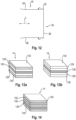
- the cover 14 can be designed as a monofilm. Fig. 13a, Fig. 13b and Fig. 14 Embodiments of the cover 14 are shown in which the cover 14 is formed by several layers or by a plastic plate.
- the cover 14 comprises five layers.
- a middle layer is designed as a barrier layer 126, for example in the form of an aluminum layer.
- the layers are numbered from top to bottom in the figures, so that the uppermost layer represents a first layer and a lowermost layer represents a fifth layer.
- a second layer and a fourth layer are each designed as a polyethylene layer (PE layer) 128.
- the uppermost and lowermost layers, ie the first layer and the fifth layer of the cover 14 are each designed as a polypropylene layer (PP layer) 130.
- the barrier layer 126 prevents water vapor and/or oxygen from penetrating the chamber 20. Particularly in the case of chemically active masses, water vapor and/or oxygen can cause the mass arranged in the chamber 20 to react, thereby reducing its durability or changing its composition. In addition, the material in the chamber 20 can advantageously not outgas due to the barrier layer 126.
- Fig. 13b An alternative structure of the cover 14 with five layers is shown.
- the middle layer is again designed as a barrier layer 126.
- the first layer and the fifth layer 130 are also made of polyethylene.
- the design of the cover 14 in Fig. 14 has five layers, with the barrier layer 126 forming the fourth layer.
- the first layer, the third layer and the fifth layer are each designed as a PE layer 130 in this embodiment.
- the second layer 132 represents a layer 132 of bi-axially arranged polypropylene.
- the cover 14 can be made of a particularly rigid plastic plate, which preferably comprises PE, PP, PET, PVC, ABS, PA, PLA or comparable materials.
- the cover 14 is in turn connected by gluing or welding to the insert 16 of the embodiment of the Fig. 2 or Fig. 2b connected to insert 16.
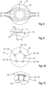
- predetermined breaking areas 88 are shown below, which differ from one another in terms of their shape. In all of these figures, a detailed view of a plan view of the cover 14 is shown, with the predetermined breaking area 88 being shown in more detail in each case.
- the predetermined breaking area 88 is designed in several parts and in this case has eight sub-areas, each of which extends radially outwards from a center point 134 to the center point 134 in a substantially straight line, so that the predetermined breaking area 88 forms a star-shaped pattern.
- the predetermined breaking area 88 thus represents a symmetrical, in this case point-symmetrical pattern.
- the predetermined breaking region 88 has four sub-regions, which in turn extend from the center point 134 essentially in a straight line in the radial direction outwards, so that the predetermined breaking region represents a cross-shaped pattern, which here is point-symmetrical to the center point 134.
- the one in Fig. 17 The predetermined breaking area 88 shown is formed by a straight line.
- the predetermined breaking area 88 is formed by a circular boundary, which can be designed as a continuous line or as a perforation.
- the line or the perforation delimits the predetermined breaking area 88 from the further area of the cover 14 lying outside the line or the perforation.
- the predetermined breaking area 88 is defined by a substantially semicircular line, which in turn can be designed as a perforation or a continuous line.
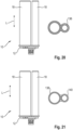
- Fig. 20 shows a side view and a top view of another embodiment of a cartridge 10 with two foil bags 18, wherein the foil bags 18 are connected to the head part 12 in a common welding process.
- the inherently rigid insert 16 is first connected to the foil bag 18 and then filled with a mass 102 through the passage 60. Then again, the passage 60 is closed with the cover 14, wherein the cover 14 is connected to the insert 16 in the manner described in more detail above and in particular is welded on.
- the cover 14 is designed to be weldable on both sides, so that in a further step the film bags 18 are connected to the head part 12 in a welding process.
- This is possible in the design according to Fig. 20 for both foil bags 18 with a common welding tool 136 and in the execution according to Fig. 21 for each film bag 18 with two separate welding tools 138, 140 and thus can be carried out independently of each other, wherein one welding tool 138 is assigned to one film bag 18 and the other welding tool 140 is assigned to the other film bag 18.
- the inserts 16 have a corresponding counter-contour to the head part 12, so that the inserts 16, when connected to the head part 12, lie essentially flat against the head part 12 via the cover 14.
- the respective, in Fig. 20 and Fig. 21 The welding tool 136, 138, 140 shown only schematically is guided from a side facing away from the head part 12 over the foil bags 18 to a contact area of the head part 12 with the insert 16, wherein the welding tools 138, 140 weld the respective foil bags 18 and the corresponding contours of the insert 16 and the head part 12 in the embodiment according to Fig. 21 completely enclose the circumference, so that a connection that runs completely around the circumference is created between the head part 12 and the film bag 18 via the cover 14.
- the connections of the two film bags 18 to the head part 12 can be carried out simultaneously, partially overlapping or one after the other.
- the common welding tool 140 When executing according to Fig. 20 the common welding tool 140, with which the connection of both film bags 18 to the head part 12 is possible in a single work step, comprises the film bags 18 on the circumference, for example, except for an area of the film bags 18 facing each other, so that a connection is created between the head part 12 and the two film bags 18 that runs completely around the outside of both film bags 18 via the respective covers.
- an inductive and contactless welding process for example a high-frequency welding process
- the cover 14 preferably has an aluminum layer that is heated during the welding process, the heat being conducted through the other layers of the cover 14 to the inserts, which are made in particular of plastic, and the head part 12, thereby achieving the welding. This achieves a very targeted energy input at the point where the welded connection is to be created.
- the cartridge 10 comprises one or two chambers 20 and a corresponding number of covers 14, inserts 16, foil bags 18, receptacles 66 and outlet channels 80.
- any number of the above-mentioned components is possible.
Landscapes
- Engineering & Computer Science (AREA)
- Mechanical Engineering (AREA)
- Packages (AREA)
- Tubes (AREA)
- Containers And Packaging Bodies Having A Special Means To Remove Contents (AREA)
Claims (14)
- Cartouche (10) pour un dispositif d'expulsion par pression, comportant au moins un sachet en film (18) allongé qui n'est pas réalisé de manière intrinsèquement rigide et qui présente une chambre (20) pour la réception d'une matière (102) et une partie formant tête (12) permettant de coopérer avec le sachet en film (18), dans laquelle le sachet en film (18) présente une ouverture (22) sur un côté tourné vers la partie formant tête (12), laquelle est fermée par un élément de recouvrement (14), dans laquelle l'élément de recouvrement (14) présente une zone de rupture (88), caractérisée en ce qu'un insert (16) mis en oeuvre de manière intrinsèquement rigide est prévu, lequel est relié au sachet en film (18) sur le côté tourné vers la partie formant tête (12) et présente un passage (60), dans laquelle l'élément de recouvrement (14) est relié à l'insert (16) et ferme le passage (60).
- Cartouche (10) selon la revendication 1, caractérisée en ce que l'élément de recouvrement (14) présente dans la zone de rupture (88), au moins dans certaines zones, une épaisseur de matériau plus faible que dans une autre zone de l'élément de recouvrement (14).
- Cartouche (10) selon l'une des revendications 1 ou 2, caractérisée en ce que l'élément de recouvrement (14) présente dans la zone de rupture (88), au moins dans certaines zones, une épaisseur de matériau plus importante que dans une autre zone de l'élément de recouvrement (14).
- Cartouche (10) selon l'une des revendications précédentes, caractérisée en ce que la zone de rupture (88) de l'élément de recouvrement (14) est délimitée par une atténuation de matériau linéaire.
- Cartouche (10) selon l'une des revendications précédentes, caractérisée en ce que la zone de rupture (88) de l'élément de recouvrement (14) présente une résistance de matériau définie différente de celle d'une autre zone de l'élément de recouvrement (14).
- Cartouche (10) selon l'une des revendications précédentes, caractérisée en ce que l'insert (16) est mis en oeuvre sous forme conique sur un côté orienté vers la partie formant tête (12).
- Cartouche (10) selon l'une des revendications précédentes, caractérisée en ce que l'insert (16) présente au moins une ouverture d'aération (112) indépendante du passage (60) et/ou au moins une fente d'aération (116) indépendante du passage (60) et/ou en ce que le passage (60) de l'insert (16) présente au moins une rainure d'aération (122) dans une zone orientée vers l'axe central du sachet en film (18).
- Cartouche (10) selon l'une des revendications précédentes, caractérisée en ce que l'insert (16) et la partie formant tête (12) présentent, dans des zones orientées les unes vers les autres, un contour interagissant respectivement et mis en oeuvre de manière sensiblement de manière opposée, dans laquelle l'élément de recouvrement (14) disposé dans la zone des contours est mise en oeuvre de manière soudable.
- Cartouche (10) selon l'une des revendications précédentes, caractérisée en ce que le sachet en film (18) est formé par un tube en film (26) cylindrique qui est fermé côté fond par une partie formant fond (24) qui est en particulier collée et/ou soudée au tube en film (26).
- Procédé de fabrication d'une cartouche (10) pour un dispositif d'expulsion par pression selon l'une des revendications 1 à 9, au moyen des étapes suivantes :- fourniture d'un sachet en film (18) formant une chambre (20) comportant une ouverture (22),- liaison d'un insert (16) mis en oeuvre de manière intrinsèquement rigide au sachet en film,- remplissage de la chambre (20) avec une matière (102) par l'ouverture (22),- fermeture de l'ouverture (22) avec un élément de recouvrement (14), et- fabrication d'une zone de rupture (88) définie de l'élément de recouvrement (14).
- Procédé selon la revendication 10, caractérisé en ce qu'une partie formant fond (24) et un insert (16) indéformable sont reliés au tube en film (26) de sorte qu'un sachet en film (18) en résulte, lequel comprend une chambre (20) qui est délimitée par le sachet en film (18), l'insert (16) et la partie formant fond (24), dans lequel l'insert (16) présente un passage (60).
- Procédé selon la revendication 11, caractérisé en ce que la zone de rupture (88) de l'élément de recouvrement (14) est fabriquée au moyen d'un laser, d'une atténuation par gaufrage à chaud, par une entaille ou par un processus de soudage de l'élément de recouvrement (14) au niveau de l'insert (16).
- Procédé selon l'une des revendications 11 ou 12, caractérisé par les étapes suivantes :- fermeture du passage (60) avec un élément de recouvrement (14),- liaison de l'insert (16) à la partie formant tête (12) dans un processus de soudage, dans lequel le processus de soudage est mis en oeuvre par un apport de chaleur dans l'élément de recouvrement (14).
- Procédé selon l'une des revendications 10 à 13, caractérisé en ce que l'insert (16) possède au moins un prolongement de matière (54), en particulier un prolongement de matière (54) entourant le passage (60), lequel fond pendant la fermeture du passage (60).
Applications Claiming Priority (2)
| Application Number | Priority Date | Filing Date | Title |
|---|---|---|---|
| EP19216079.4A EP3835229A1 (fr) | 2019-12-13 | 2019-12-13 | Cartouche et procédé de fabrication d'une cartouche |
| PCT/EP2020/084023 WO2021115834A1 (fr) | 2019-12-13 | 2020-12-01 | Cartouche et procédé de production d'une cartouche |
Publications (2)
| Publication Number | Publication Date |
|---|---|
| EP4072968A1 EP4072968A1 (fr) | 2022-10-19 |
| EP4072968B1 true EP4072968B1 (fr) | 2025-02-05 |
Family
ID=68916441
Family Applications (2)
| Application Number | Title | Priority Date | Filing Date |
|---|---|---|---|
| EP19216079.4A Withdrawn EP3835229A1 (fr) | 2019-12-13 | 2019-12-13 | Cartouche et procédé de fabrication d'une cartouche |
| EP20812088.1A Active EP4072968B1 (fr) | 2019-12-13 | 2020-12-01 | Cartouche et procédé de fabrication d'une cartouche |
Family Applications Before (1)
| Application Number | Title | Priority Date | Filing Date |
|---|---|---|---|
| EP19216079.4A Withdrawn EP3835229A1 (fr) | 2019-12-13 | 2019-12-13 | Cartouche et procédé de fabrication d'une cartouche |
Country Status (2)
| Country | Link |
|---|---|
| EP (2) | EP3835229A1 (fr) |
| WO (1) | WO2021115834A1 (fr) |
Families Citing this family (4)
| Publication number | Priority date | Publication date | Assignee | Title |
|---|---|---|---|---|
| USD1095837S1 (en) | 2021-07-22 | 2025-09-30 | Medmix Switzerland Ag | Cartridge sleeve |
| DE102022117176B4 (de) * | 2022-07-11 | 2025-06-26 | Tesa Se | Verfahren zum dauerhaften Verschließen von Löchern mit Überdrucksicherung, Klebeelement für das Verfahren, Überdruckgesichertes Substrat und Verwendung eines Klebeelements |
| EP4480849A1 (fr) | 2023-06-19 | 2024-12-25 | Hilti Aktiengesellschaft | Cartouche |
| EP4501599A1 (fr) | 2023-08-01 | 2025-02-05 | Hilti Aktiengesellschaft | Procédé de fabrication d'une cartouche |
Citations (2)
| Publication number | Priority date | Publication date | Assignee | Title |
|---|---|---|---|---|
| EP1331174B1 (fr) * | 2000-09-25 | 2010-11-24 | Sunstar Engineering Inc. | Contenant mou et procede de fabrication du contenant, et corps rempli d'un liquide conditionne a tres forte viscosite |
| EP2511194B1 (fr) * | 2011-04-15 | 2016-08-03 | HILTI Aktiengesellschaft | Cartouche plastique et procédé de fabrication d'une cartouche plastique |
Family Cites Families (1)
| Publication number | Priority date | Publication date | Assignee | Title |
|---|---|---|---|---|
| DE29501255U1 (de) | 1995-01-27 | 1995-03-09 | Hilti Ag, Schaan | Folienbeutelpackung mit Folienbeutel und Bodenteil |
-
2019
- 2019-12-13 EP EP19216079.4A patent/EP3835229A1/fr not_active Withdrawn
-
2020
- 2020-12-01 EP EP20812088.1A patent/EP4072968B1/fr active Active
- 2020-12-01 WO PCT/EP2020/084023 patent/WO2021115834A1/fr not_active Ceased
Patent Citations (2)
| Publication number | Priority date | Publication date | Assignee | Title |
|---|---|---|---|---|
| EP1331174B1 (fr) * | 2000-09-25 | 2010-11-24 | Sunstar Engineering Inc. | Contenant mou et procede de fabrication du contenant, et corps rempli d'un liquide conditionne a tres forte viscosite |
| EP2511194B1 (fr) * | 2011-04-15 | 2016-08-03 | HILTI Aktiengesellschaft | Cartouche plastique et procédé de fabrication d'une cartouche plastique |
Also Published As
| Publication number | Publication date |
|---|---|
| EP3835229A1 (fr) | 2021-06-16 |
| WO2021115834A1 (fr) | 2021-06-17 |
| EP4072968A1 (fr) | 2022-10-19 |
Similar Documents
| Publication | Publication Date | Title |
|---|---|---|
| EP4072968B1 (fr) | Cartouche et procédé de fabrication d'une cartouche | |
| EP1140259B1 (fr) | Ampoule multichambre servant a distribuer un melange constitue de plusieurs substances | |
| EP2768619B1 (fr) | Cartouche à plusieurs constituants | |
| EP2511194B1 (fr) | Cartouche plastique et procédé de fabrication d'une cartouche plastique | |
| EP4072970B1 (fr) | Cartouche et procédé de fabrication d'une cartouche | |
| WO2011023399A1 (fr) | Procédé et dispositif permettant d'appliquer une masse d'étanchéité sur une surface | |
| EP4072969B1 (fr) | Cartouche et procédé de fabrication d'une cartouche | |
| EP4232398B1 (fr) | Système de cartouche, machine de préparation de boissons et procédé de production d'un système de cartouche | |
| WO2023170036A1 (fr) | Système de cartouche | |
| EP4072740B1 (fr) | Cartouche pour un dispositif d'extrusion | |
| DE60133103T2 (de) | Behälter | |
| EP2906481B1 (fr) | Procédé de fabrication d'un tel emballage en film | |
| DE102005000832A1 (de) | Behälter für eine Mehrkomponentenreaktion | |
| EP3834948A1 (fr) | Procédé de fabrication d'une cartouche et cartouche | |
| EP3885123A1 (fr) | Cartouche et procédé de fabrication d'une cartouche | |
| DE102008007306A1 (de) | Auspressvorrichtung für plastische Massen | |
| EP3887279B1 (fr) | Cartouche pour matériaux à plusieurs composants | |
| DE4432718A1 (de) | Packung mit flacher Öffnungsvorrichtung und Werkzeug zur Herstellung derselben | |
| EP4501599A1 (fr) | Procédé de fabrication d'une cartouche | |
| EP1947028A2 (fr) | Dispositif destiné au stockage et au dosage de plusieurs composants | |
| EP4480849A1 (fr) | Cartouche | |
| EP4186814A1 (fr) | Cartouche pour un dispositif d'extrusion | |
| CH712945A1 (de) | Verfahren zur Herstellung eines flächigen Verschlusselements mit wenigstens einer Dünnstelle zum Verschliessen einer Behälteröffnung. | |
| WO2026052646A1 (fr) | Cartouche comprenant un sachet tubulaire, et procédé d'utilisation de la cartouche |
Legal Events
| Date | Code | Title | Description |
|---|---|---|---|
| STAA | Information on the status of an ep patent application or granted ep patent |
Free format text: STATUS: UNKNOWN |
|
| STAA | Information on the status of an ep patent application or granted ep patent |
Free format text: STATUS: THE INTERNATIONAL PUBLICATION HAS BEEN MADE |
|
| PUAI | Public reference made under article 153(3) epc to a published international application that has entered the european phase |
Free format text: ORIGINAL CODE: 0009012 |
|
| STAA | Information on the status of an ep patent application or granted ep patent |
Free format text: STATUS: REQUEST FOR EXAMINATION WAS MADE |
|
| 17P | Request for examination filed |
Effective date: 20220713 |
|
| AK | Designated contracting states |
Kind code of ref document: A1 Designated state(s): AL AT BE BG CH CY CZ DE DK EE ES FI FR GB GR HR HU IE IS IT LI LT LU LV MC MK MT NL NO PL PT RO RS SE SI SK SM TR |
|
| DAV | Request for validation of the european patent (deleted) | ||
| DAX | Request for extension of the european patent (deleted) | ||
| GRAP | Despatch of communication of intention to grant a patent |
Free format text: ORIGINAL CODE: EPIDOSNIGR1 |
|
| STAA | Information on the status of an ep patent application or granted ep patent |
Free format text: STATUS: GRANT OF PATENT IS INTENDED |
|
| GRAS | Grant fee paid |
Free format text: ORIGINAL CODE: EPIDOSNIGR3 |
|
| INTG | Intention to grant announced |
Effective date: 20241011 |
|
| GRAA | (expected) grant |
Free format text: ORIGINAL CODE: 0009210 |
|
| STAA | Information on the status of an ep patent application or granted ep patent |
Free format text: STATUS: THE PATENT HAS BEEN GRANTED |
|
| AK | Designated contracting states |
Kind code of ref document: B1 Designated state(s): AL AT BE BG CH CY CZ DE DK EE ES FI FR GB GR HR HU IE IS IT LI LT LU LV MC MK MT NL NO PL PT RO RS SE SI SK SM TR |
|
| REG | Reference to a national code |
Ref country code: GB Ref legal event code: FG4D Free format text: NOT ENGLISH |
|
| REG | Reference to a national code |
Ref country code: CH Ref legal event code: EP |
|
| REG | Reference to a national code |
Ref country code: IE Ref legal event code: FG4D Free format text: LANGUAGE OF EP DOCUMENT: GERMAN |
|
| REG | Reference to a national code |
Ref country code: DE Ref legal event code: R096 Ref document number: 502020010358 Country of ref document: DE |
|
| REG | Reference to a national code |
Ref country code: NL Ref legal event code: MP Effective date: 20250205 |
|
| PG25 | Lapsed in a contracting state [announced via postgrant information from national office to epo] |
Ref country code: RS Free format text: LAPSE BECAUSE OF FAILURE TO SUBMIT A TRANSLATION OF THE DESCRIPTION OR TO PAY THE FEE WITHIN THE PRESCRIBED TIME-LIMIT Effective date: 20250505 |
|
| PG25 | Lapsed in a contracting state [announced via postgrant information from national office to epo] |
Ref country code: FI Free format text: LAPSE BECAUSE OF FAILURE TO SUBMIT A TRANSLATION OF THE DESCRIPTION OR TO PAY THE FEE WITHIN THE PRESCRIBED TIME-LIMIT Effective date: 20250205 |
|
| PG25 | Lapsed in a contracting state [announced via postgrant information from national office to epo] |
Ref country code: PL Free format text: LAPSE BECAUSE OF FAILURE TO SUBMIT A TRANSLATION OF THE DESCRIPTION OR TO PAY THE FEE WITHIN THE PRESCRIBED TIME-LIMIT Effective date: 20250205 |
|
| PG25 | Lapsed in a contracting state [announced via postgrant information from national office to epo] |
Ref country code: ES Free format text: LAPSE BECAUSE OF FAILURE TO SUBMIT A TRANSLATION OF THE DESCRIPTION OR TO PAY THE FEE WITHIN THE PRESCRIBED TIME-LIMIT Effective date: 20250205 |
|
| REG | Reference to a national code |
Ref country code: LT Ref legal event code: MG9D |
|
| PG25 | Lapsed in a contracting state [announced via postgrant information from national office to epo] |
Ref country code: NO Free format text: LAPSE BECAUSE OF FAILURE TO SUBMIT A TRANSLATION OF THE DESCRIPTION OR TO PAY THE FEE WITHIN THE PRESCRIBED TIME-LIMIT Effective date: 20250505 Ref country code: IS Free format text: LAPSE BECAUSE OF FAILURE TO SUBMIT A TRANSLATION OF THE DESCRIPTION OR TO PAY THE FEE WITHIN THE PRESCRIBED TIME-LIMIT Effective date: 20250605 |
|
| PG25 | Lapsed in a contracting state [announced via postgrant information from national office to epo] |
Ref country code: NL Free format text: LAPSE BECAUSE OF FAILURE TO SUBMIT A TRANSLATION OF THE DESCRIPTION OR TO PAY THE FEE WITHIN THE PRESCRIBED TIME-LIMIT Effective date: 20250205 |
|
| PG25 | Lapsed in a contracting state [announced via postgrant information from national office to epo] |
Ref country code: HR Free format text: LAPSE BECAUSE OF FAILURE TO SUBMIT A TRANSLATION OF THE DESCRIPTION OR TO PAY THE FEE WITHIN THE PRESCRIBED TIME-LIMIT Effective date: 20250205 |
|
| PG25 | Lapsed in a contracting state [announced via postgrant information from national office to epo] |
Ref country code: LV Free format text: LAPSE BECAUSE OF FAILURE TO SUBMIT A TRANSLATION OF THE DESCRIPTION OR TO PAY THE FEE WITHIN THE PRESCRIBED TIME-LIMIT Effective date: 20250205 Ref country code: PT Free format text: LAPSE BECAUSE OF FAILURE TO SUBMIT A TRANSLATION OF THE DESCRIPTION OR TO PAY THE FEE WITHIN THE PRESCRIBED TIME-LIMIT Effective date: 20250605 |
|
| PG25 | Lapsed in a contracting state [announced via postgrant information from national office to epo] |
Ref country code: BG Free format text: LAPSE BECAUSE OF FAILURE TO SUBMIT A TRANSLATION OF THE DESCRIPTION OR TO PAY THE FEE WITHIN THE PRESCRIBED TIME-LIMIT Effective date: 20250205 Ref country code: GR Free format text: LAPSE BECAUSE OF FAILURE TO SUBMIT A TRANSLATION OF THE DESCRIPTION OR TO PAY THE FEE WITHIN THE PRESCRIBED TIME-LIMIT Effective date: 20250506 |
|
| PG25 | Lapsed in a contracting state [announced via postgrant information from national office to epo] |
Ref country code: SE Free format text: LAPSE BECAUSE OF FAILURE TO SUBMIT A TRANSLATION OF THE DESCRIPTION OR TO PAY THE FEE WITHIN THE PRESCRIBED TIME-LIMIT Effective date: 20250205 |
|
| PG25 | Lapsed in a contracting state [announced via postgrant information from national office to epo] |
Ref country code: SM Free format text: LAPSE BECAUSE OF FAILURE TO SUBMIT A TRANSLATION OF THE DESCRIPTION OR TO PAY THE FEE WITHIN THE PRESCRIBED TIME-LIMIT Effective date: 20250205 |
|
| PG25 | Lapsed in a contracting state [announced via postgrant information from national office to epo] |
Ref country code: DK Free format text: LAPSE BECAUSE OF FAILURE TO SUBMIT A TRANSLATION OF THE DESCRIPTION OR TO PAY THE FEE WITHIN THE PRESCRIBED TIME-LIMIT Effective date: 20250205 |
|
| PG25 | Lapsed in a contracting state [announced via postgrant information from national office to epo] |
Ref country code: IT Free format text: LAPSE BECAUSE OF FAILURE TO SUBMIT A TRANSLATION OF THE DESCRIPTION OR TO PAY THE FEE WITHIN THE PRESCRIBED TIME-LIMIT Effective date: 20250205 |
|
| PG25 | Lapsed in a contracting state [announced via postgrant information from national office to epo] |
Ref country code: EE Free format text: LAPSE BECAUSE OF FAILURE TO SUBMIT A TRANSLATION OF THE DESCRIPTION OR TO PAY THE FEE WITHIN THE PRESCRIBED TIME-LIMIT Effective date: 20250205 Ref country code: CZ Free format text: LAPSE BECAUSE OF FAILURE TO SUBMIT A TRANSLATION OF THE DESCRIPTION OR TO PAY THE FEE WITHIN THE PRESCRIBED TIME-LIMIT Effective date: 20250205 |
|
| PG25 | Lapsed in a contracting state [announced via postgrant information from national office to epo] |
Ref country code: RO Free format text: LAPSE BECAUSE OF FAILURE TO SUBMIT A TRANSLATION OF THE DESCRIPTION OR TO PAY THE FEE WITHIN THE PRESCRIBED TIME-LIMIT Effective date: 20250205 |
|
| PG25 | Lapsed in a contracting state [announced via postgrant information from national office to epo] |
Ref country code: SK Free format text: LAPSE BECAUSE OF FAILURE TO SUBMIT A TRANSLATION OF THE DESCRIPTION OR TO PAY THE FEE WITHIN THE PRESCRIBED TIME-LIMIT Effective date: 20250205 |
|
| REG | Reference to a national code |
Ref country code: DE Ref legal event code: R097 Ref document number: 502020010358 Country of ref document: DE |
|
| PLBE | No opposition filed within time limit |
Free format text: ORIGINAL CODE: 0009261 |
|
| STAA | Information on the status of an ep patent application or granted ep patent |
Free format text: STATUS: NO OPPOSITION FILED WITHIN TIME LIMIT |
|
| REG | Reference to a national code |
Ref country code: CH Ref legal event code: L10 Free format text: ST27 STATUS EVENT CODE: U-0-0-L10-L00 (AS PROVIDED BY THE NATIONAL OFFICE) Effective date: 20251217 |
|
| REG | Reference to a national code |
Ref country code: CH Ref legal event code: U11 Free format text: ST27 STATUS EVENT CODE: U-0-0-U10-U11 (AS PROVIDED BY THE NATIONAL OFFICE) Effective date: 20260101 |
|
| PGFP | Annual fee paid to national office [announced via postgrant information from national office to epo] |
Ref country code: DE Payment date: 20251211 Year of fee payment: 6 |
|
| 26N | No opposition filed |
Effective date: 20251106 |
|
| PGFP | Annual fee paid to national office [announced via postgrant information from national office to epo] |
Ref country code: CH Payment date: 20260101 Year of fee payment: 6 |