EP4072990B1 - Grue articulée - Google Patents
Grue articulée Download PDFInfo
- Publication number
- EP4072990B1 EP4072990B1 EP20898165.4A EP20898165A EP4072990B1 EP 4072990 B1 EP4072990 B1 EP 4072990B1 EP 20898165 A EP20898165 A EP 20898165A EP 4072990 B1 EP4072990 B1 EP 4072990B1
- Authority
- EP
- European Patent Office
- Prior art keywords
- lifting
- crane
- main beam
- pillar
- link
- Prior art date
- Legal status (The legal status is an assumption and is not a legal conclusion. Google has not performed a legal analysis and makes no representation as to the accuracy of the status listed.)
- Active
Links
Images



Classifications
-
- B—PERFORMING OPERATIONS; TRANSPORTING
- B66—HOISTING; LIFTING; HAULING
- B66C—CRANES; LOAD-ENGAGING ELEMENTS OR DEVICES FOR CRANES, CAPSTANS, WINCHES, OR TACKLES
- B66C23/00—Cranes comprising essentially a beam, boom, or triangular structure acting as a cantilever and mounted for translatory of swinging movements in vertical or horizontal planes or a combination of such movements, e.g. jib-cranes, derricks, tower cranes
- B66C23/54—Cranes comprising essentially a beam, boom, or triangular structure acting as a cantilever and mounted for translatory of swinging movements in vertical or horizontal planes or a combination of such movements, e.g. jib-cranes, derricks, tower cranes with pneumatic or hydraulic motors, e.g. for actuating jib-cranes on tractors
- B66C23/545—Cranes comprising essentially a beam, boom, or triangular structure acting as a cantilever and mounted for translatory of swinging movements in vertical or horizontal planes or a combination of such movements, e.g. jib-cranes, derricks, tower cranes with pneumatic or hydraulic motors, e.g. for actuating jib-cranes on tractors with arrangements for avoiding dead centre problems during cylinder motion
-
- B—PERFORMING OPERATIONS; TRANSPORTING
- B66—HOISTING; LIFTING; HAULING
- B66C—CRANES; LOAD-ENGAGING ELEMENTS OR DEVICES FOR CRANES, CAPSTANS, WINCHES, OR TACKLES
- B66C23/00—Cranes comprising essentially a beam, boom, or triangular structure acting as a cantilever and mounted for translatory of swinging movements in vertical or horizontal planes or a combination of such movements, e.g. jib-cranes, derricks, tower cranes
- B66C23/18—Cranes comprising essentially a beam, boom, or triangular structure acting as a cantilever and mounted for translatory of swinging movements in vertical or horizontal planes or a combination of such movements, e.g. jib-cranes, derricks, tower cranes specially adapted for use in particular purposes
- B66C23/36—Cranes comprising essentially a beam, boom, or triangular structure acting as a cantilever and mounted for translatory of swinging movements in vertical or horizontal planes or a combination of such movements, e.g. jib-cranes, derricks, tower cranes specially adapted for use in particular purposes mounted on road or rail vehicles; Manually-movable jib-cranes for use in workshops; Floating cranes
- B66C23/42—Cranes comprising essentially a beam, boom, or triangular structure acting as a cantilever and mounted for translatory of swinging movements in vertical or horizontal planes or a combination of such movements, e.g. jib-cranes, derricks, tower cranes specially adapted for use in particular purposes mounted on road or rail vehicles; Manually-movable jib-cranes for use in workshops; Floating cranes with jibs of adjustable configuration, e.g. foldable
-
- B—PERFORMING OPERATIONS; TRANSPORTING
- B66—HOISTING; LIFTING; HAULING
- B66C—CRANES; LOAD-ENGAGING ELEMENTS OR DEVICES FOR CRANES, CAPSTANS, WINCHES, OR TACKLES
- B66C23/00—Cranes comprising essentially a beam, boom, or triangular structure acting as a cantilever and mounted for translatory of swinging movements in vertical or horizontal planes or a combination of such movements, e.g. jib-cranes, derricks, tower cranes
- B66C23/54—Cranes comprising essentially a beam, boom, or triangular structure acting as a cantilever and mounted for translatory of swinging movements in vertical or horizontal planes or a combination of such movements, e.g. jib-cranes, derricks, tower cranes with pneumatic or hydraulic motors, e.g. for actuating jib-cranes on tractors
-
- B—PERFORMING OPERATIONS; TRANSPORTING
- B66—HOISTING; LIFTING; HAULING
- B66C—CRANES; LOAD-ENGAGING ELEMENTS OR DEVICES FOR CRANES, CAPSTANS, WINCHES, OR TACKLES
- B66C23/00—Cranes comprising essentially a beam, boom, or triangular structure acting as a cantilever and mounted for translatory of swinging movements in vertical or horizontal planes or a combination of such movements, e.g. jib-cranes, derricks, tower cranes
- B66C23/62—Constructional features or details
- B66C23/64—Jibs
- B66C23/68—Jibs foldable or otherwise adjustable in configuration
-
- B—PERFORMING OPERATIONS; TRANSPORTING
- B60—VEHICLES IN GENERAL
- B60P—VEHICLES ADAPTED FOR LOAD TRANSPORTATION OR TO TRANSPORT, TO CARRY, OR TO COMPRISE SPECIAL LOADS OR OBJECTS
- B60P1/00—Vehicles predominantly for transporting loads and modified to facilitate loading, consolidating the load, or unloading
- B60P1/54—Vehicles predominantly for transporting loads and modified to facilitate loading, consolidating the load, or unloading using cranes for self-loading or self-unloading
-
- B—PERFORMING OPERATIONS; TRANSPORTING
- B60—VEHICLES IN GENERAL
- B60P—VEHICLES ADAPTED FOR LOAD TRANSPORTATION OR TO TRANSPORT, TO CARRY, OR TO COMPRISE SPECIAL LOADS OR OBJECTS
- B60P1/00—Vehicles predominantly for transporting loads and modified to facilitate loading, consolidating the load, or unloading
- B60P1/54—Vehicles predominantly for transporting loads and modified to facilitate loading, consolidating the load, or unloading using cranes for self-loading or self-unloading
- B60P1/5404—Vehicles predominantly for transporting loads and modified to facilitate loading, consolidating the load, or unloading using cranes for self-loading or self-unloading with a fixed base
- B60P1/5423—Vehicles predominantly for transporting loads and modified to facilitate loading, consolidating the load, or unloading using cranes for self-loading or self-unloading with a fixed base attached to the loading platform or similar
- B60P1/5433—Vehicles predominantly for transporting loads and modified to facilitate loading, consolidating the load, or unloading using cranes for self-loading or self-unloading with a fixed base attached to the loading platform or similar and having the first pivot on a vertical axis
-
- B—PERFORMING OPERATIONS; TRANSPORTING
- B66—HOISTING; LIFTING; HAULING
- B66C—CRANES; LOAD-ENGAGING ELEMENTS OR DEVICES FOR CRANES, CAPSTANS, WINCHES, OR TACKLES
- B66C2700/00—Cranes
- B66C2700/03—Cranes with arms or jibs; Multiple cranes
Definitions
- the invention relates to a crane construction arranged for lifting and moving a load hanging in the tip of the crane or for carrying and operating a tool arranged in the tip of the crane.
- a common feature of these cranes is that the movements of the lifting boom and the crane arm are controlled in a common center of rotation in the journaling of the lifting boom at the pillar.
- Another object of the invention is to provide an articulated crane, the design and composition of which result in an even crane tip speed when the crane arm is folded out and folded in, respectively.
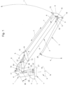
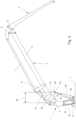
- FIGs. 1 to 5 illustrate some of the positions of the crane in motion between an almost extreme lowered position and an almost extreme upright position.
- the crane can be supported by an autonomous working platform or by a working platform that is included as part of a machine, e.g. as part of the frame of a vehicle.
- the crane can alternatively be mounted on the same vehicle upper part such as a cab, and can form part of the framework in vehicles with a rotatable upper part/cab.
- the working platform may be arranged rotatable about an imaginary mainly vertical axis, and may also be tiltable or rotatable in a vertical plane.
- angle adjusting device 10 controls the pivoting of the horizontal link 8 according to the double arrow b, the longitudinal displacement of the drawbar 7 according to the double arrow c, the pivoting of the knee link 9 according to the double arrow d and finally the crane arm 3 according to the double arrow e.
- the cylinder end of the lifting device is directly or indirectly pivotally journaled at the pillar 1 in a pivot point 22, while its piston rod end, via a pivot point 23, is articulately coupled to one end of a three-point pivotally journaled lifting yoke 24.
- the lifting yoke 24 is, at a central pivot point 25, rotatably journaled in the main beam 6 for pivoting around the pivot point 25 according to the double arrow g.
- the lifting yoke 24 is at its other end, at the pivot point 26, articulately connected to a first end of a strut 27, the second end of which is articulately connected to the horizontal link 8, more specifically at the pivot point 14.
- the strut 27 is of a fixed length, which means that the rotation of the lifting yoke 24 around the pivot point 25 slavishly follows the rotation of the horizontal link 8 around the pivot point 13.
- a connection 32 may, if applicable, be arranged for refilling or for emptying gas from the pillar 1 in order thus to adjust the gas pressure, primarily for balancing the dead weight of crane arm, or alternatively for balancing of a load hanging in the crane arm tip.
- Fig. 6 which is partially broken away, illustrates how the change in length of the lever ⁇ M depends on two coordinated rotations: the rotation of the pivot point 25 about the pivot point 4, and the rotation of the pivot point 23 around the pivot point 25.
- the pivot point 25 moves clockwise and anti-clockwise, respectively, along the periphery of a circle CL, the radius of which is the distance RL between the pivot points 4 and 25.
- the pivot point 23 is moved clockwise and counterclockwise, respectively, along the periphery of a circle CS, the radius of which is the distance RS between the pivot points 25 and 23.
- the change in length ⁇ M of the lever may amount to a maximum of the diameter of the circle CS, i.e. ⁇ M ⁇ 2RS.
- a limiting condition when dimensioning the crane is that in the fully retracted position of the crane arm with the lifting boom in a horizontal position (such as in transport position), the lifting point 23 of the lifting device must still be in front of a vertical line D through the pivot point 4, since otherwise a locked position is risked.
- the radius RS i.e. the distance between the pivot points 23 and 25 in the lifting yoke 24, shall thus be smaller than the distance RL between the pivot points 4 and 25 in the beam 6, i.e. RS ⁇ RL.
- RS preferably amounts to the order of 30-70 % of RL, and is at least in the order of 40-60 % of RL, and preferably constitutes about 50 % of RL.
- the crane arm tip 28 can be controlled to perform a substantially horizontal movement when folding out or folding in the crane arm 3. This is illustrated in Fig. 7 , in which a number of movement paths for the crane arm tip 28 are shown h1, h2, h3, h4 and h5 at different heights within the working area of the crane.
- Fig. 7 is a diagram illustrating the movement pattern of a crane with a geometry corresponding to the schematically shown crane in the exemplary embodiment. In this geometry these percentages are also calculated which in Fig. 7 indicate the lifting force resulting in the crane arm tip as part of the pressure force exerted by the lifting device 20 at different radial distances r1 - r5 from the inner pivot 4. Fig. 7 illustrates how the required torque can be equalized within the working range of the crane as a result of the proportionally varying length of the lever (and the associated torque arm).
- the pillar 1 is suitably formed with a convexly shaped guide surface 33 for forcibly guiding the lifting yoke 24 and the journaling of the lifting cylinder in the pivot point 23 during the movement of the crane arm out of an extremely raised or lowered position.
- a fixed position 34 may be formed as a recess in the underside of the beam 6 for receiving the horizontal link and the pivot point 23 in the extreme position.
- the crane described above can be adapted for many different applications, of which the following are just a few examples of the crane's usefulness of the crane:
Landscapes
- Engineering & Computer Science (AREA)
- Mechanical Engineering (AREA)
- Jib Cranes (AREA)
- Forklifts And Lifting Vehicles (AREA)
Claims (7)
- Grue comprenant au moins trois parties interconnectées de manière articulée dans un plan sous la forme d'un pilier (1), d'un bras de grue (3) et d'une flèche de levage (2) insérée entre ceux-ci,- la flèche de levage (2) comportant un longeron principal (6) qui est relié de manière pivotante au pilier (1) par l'intermédiaire d'une articulation intérieure (4) et qui est relié de manière pivotante au bras de grue (3) par l'intermédiaire d'une articulation extérieure (5),- la flèche de levage (2) comprenant une entretoise parallèle (7) pivotant parallèlement au longeron principal (6), qui, par l'intermédiaire d'une liaison intérieure (8) accouplée de manière pivotante entre l'entretoise parallèle (7) et le longeron principal (6), ainsi que d'une liaison extérieure (9) accouplée de manière pivotante entre l'entretoise parallèle (7) et le longeron principal (6), forme avec le longeron principal (6) une géométrie trapézoïdale parallèle,- la liaison intérieure, ci-après dénommée liaison horizontale (8), étant conçue pour être actionnée par un dispositif de réglage angulaire (10) agissant entre le longeron principal (6) et la liaison horizontale (8) de sorte à pivoter autour de son point de pivotement (13) dans le longeron principal (6), ainsi que par l'intermédiaire de l'entretoise parallèle (7) et de la liaison extérieure, ci-après dénommée liaison coudée (9), pour régler la position angulaire du bras de grue (3) par rapport au longeron principal (6) dans l'articulation extérieure (5),- une fourche de levage (24) étant tourillonnée de manière pivotante dans le longeron principal (6), qui pour lever et abaisser la flèche de levage (2) est actionnée par un dispositif de levage (20),- la liaison horizontale (8) et la fourche de levage (24) étant mutuellement reliées par l'intermédiaire d'une entretoise (27) de longueur fixe reliée de manière articulée aux deux, la fourche de levage (24) étant entraînée servilement dans le pivotement du bras horizontal (8) sous l'action du dispositif de réglage angulaire (10), caractérisée en ce- que la fourche de levage (24) forme un levier à deux bras qui, à une extrémité, est relié de manière articulée au dispositif de levage (20) en un point de pivotement (23) et, à une extrémité opposée, est relié de manière articulée à l'entretoise (27) en un point de pivotement (26), et est monté de manière pivotante dans le longeron principal (6) par l'intermédiaire d'un point de pivotement (25) situé entre les points de pivotement (23) et (26), séparé du tourillon (4) du longeron principal (6) dans le pilier (1).
- Grue selon la revendication 1, une distance RS entre les points de pivotement (23) et (25) étant inférieure à une distance RL entre les points de pivotement (4) et (25), et la longueur M d'un levier entre les points de pivotement (4) et (23) variant selon la formule ΔM ≤ 2RS (RS < RL) proportionnellement au dépliage (e) du bras de grue (3) par rapport à la flèche de levage (2).
- Grue selon la revendication 2, la longueur de RS étant de l'ordre de 30 à 70 % de RL, et étant au moins de l'ordre de 40 à 60 % de RL, et de préférence constituant environ 50 % de RL.
- Grue selon l'une quelconque des revendications précédentes, le pilier (1) présentant une surface convexe (33) faisant face à la fourche de levage (24) et permettant de guider de force la fourche de levage (24) lorsque le bras de grue est pivoté à partir d'une position extrême.
- Grue selon l'une quelconque des revendications précédentes, un moyen de stockage d'énergie pneumatique ou gaz-hydraulique (29) étant relié de manière articulée à la fourche de levage (24) et conçu pour fonctionner parallèlement au dispositif de levage (20).
- Grue selon la revendication 5, le moyen de stockage d'énergie (29) étant disposé en liaison fluidique (31) avec un volume rempli de gaz (30) à l'intérieur du pilier (1).
- Grue selon la revendication 6, le pilier (1) comprenant une liaison (32) pour remplir et vider le gaz, respectivement, du volume (30) à l'intérieur du pilier.
Applications Claiming Priority (2)
| Application Number | Priority Date | Filing Date | Title |
|---|---|---|---|
| SE1930401A SE543971C2 (sv) | 2019-12-12 | 2019-12-12 | Ledad lyftarm |
| PCT/SE2020/051197 WO2021118446A1 (fr) | 2019-12-12 | 2020-12-11 | Grue articulée |
Publications (4)
| Publication Number | Publication Date |
|---|---|
| EP4072990A1 EP4072990A1 (fr) | 2022-10-19 |
| EP4072990A4 EP4072990A4 (fr) | 2024-01-03 |
| EP4072990B1 true EP4072990B1 (fr) | 2025-03-12 |
| EP4072990C0 EP4072990C0 (fr) | 2025-03-12 |
Family
ID=76330615
Family Applications (1)
| Application Number | Title | Priority Date | Filing Date |
|---|---|---|---|
| EP20898165.4A Active EP4072990B1 (fr) | 2019-12-12 | 2020-12-11 | Grue articulée |
Country Status (4)
| Country | Link |
|---|---|
| EP (1) | EP4072990B1 (fr) |
| PL (1) | PL4072990T3 (fr) |
| SE (1) | SE543971C2 (fr) |
| WO (1) | WO2021118446A1 (fr) |
Family Cites Families (8)
| Publication number | Priority date | Publication date | Assignee | Title |
|---|---|---|---|---|
| SE463668B (sv) * | 1989-05-16 | 1991-01-07 | Motrac Gunnarson & Larsson Hb | Kran |
| FI107328B (fi) * | 1996-04-30 | 2001-07-13 | Risto Heikkilae | Kuormain |
| SE521258C2 (sv) * | 1997-03-03 | 2003-10-14 | Motrac Ab | Tvåarmat system |
| FI20010346A0 (fi) * | 2001-02-22 | 2001-02-22 | Risto Heikkilae | Kuormain |
| FI20055089A7 (fi) * | 2005-02-23 | 2006-08-24 | Ponsse Oyj | Liikeratanosturi |
| FI119636B (fi) * | 2007-10-12 | 2009-01-30 | John Deere Forestry Oy | Nosturirakenne ja lisävarren rakenne |
| ES2457238T3 (es) * | 2011-09-07 | 2014-04-25 | Epsilon Kran Gmbh. | Brazo de grúa telescópico |
| FI124684B (fi) * | 2012-12-03 | 2014-12-15 | Ponsse Oyj | Nosturi |
-
2019
- 2019-12-12 SE SE1930401A patent/SE543971C2/sv unknown
-
2020
- 2020-12-11 EP EP20898165.4A patent/EP4072990B1/fr active Active
- 2020-12-11 PL PL20898165.4T patent/PL4072990T3/pl unknown
- 2020-12-11 WO PCT/SE2020/051197 patent/WO2021118446A1/fr not_active Ceased
Also Published As
| Publication number | Publication date |
|---|---|
| PL4072990T3 (pl) | 2025-11-03 |
| EP4072990C0 (fr) | 2025-03-12 |
| SE543971C2 (sv) | 2021-10-12 |
| EP4072990A1 (fr) | 2022-10-19 |
| SE1930401A1 (sv) | 2021-06-13 |
| WO2021118446A1 (fr) | 2021-06-17 |
| EP4072990A4 (fr) | 2024-01-03 |
Similar Documents
| Publication | Publication Date | Title |
|---|---|---|
| CN101292072A (zh) | 尤其用于大型机械手和移动式混凝土泵的作业杆 | |
| US6695158B2 (en) | Crane with self-raising mast | |
| US8113363B2 (en) | Adjusting mechanism for a winch | |
| US8813600B2 (en) | Apparatus for moving a platform | |
| EP3020874B1 (fr) | Système de commande hydraulique pour commander un dispositif mobile | |
| US6311464B1 (en) | Mowing machine | |
| US4364705A (en) | Loader mechanism | |
| CA1037433A (fr) | Commande a levier, particulierement pour dispositif de levage | |
| WO2021118446A1 (fr) | Grue articulée | |
| ITMO20110048A1 (it) | Macchina operatrice semovente con assale a carreggiata variabile | |
| WO1987007474A1 (fr) | Machine de sylviculture equipee d'une grue | |
| US4519741A (en) | Mobile yard crane for handling containers | |
| CN107105611A (zh) | 具有辅助底盘的农用工作机具 | |
| US5577878A (en) | Work machine | |
| RU2158207C1 (ru) | Манипулятор | |
| CN112456387A (zh) | 基于叉车平台的装载机构及叉车 | |
| CA2828008C (fr) | Pelle excavatrice suspendue | |
| EP2197779B1 (fr) | Bras mécanique articulé | |
| FI119636B (fi) | Nosturirakenne ja lisävarren rakenne | |
| JP2022088775A (ja) | 高所作業車 | |
| CN223892381U (zh) | 一种适用于农作物叉装用的弯折伸缩臂装置 | |
| RU2783604C1 (ru) | Фронтальный погрузчик с расширенной рабочей зоной | |
| RU2191740C1 (ru) | Стреловое устройство грузоподъемной машины | |
| RU2193518C1 (ru) | Гидравлический кран-манипулятор | |
| JP2023057882A (ja) | 煽り抑制装置 |
Legal Events
| Date | Code | Title | Description |
|---|---|---|---|
| STAA | Information on the status of an ep patent application or granted ep patent |
Free format text: STATUS: THE INTERNATIONAL PUBLICATION HAS BEEN MADE |
|
| PUAI | Public reference made under article 153(3) epc to a published international application that has entered the european phase |
Free format text: ORIGINAL CODE: 0009012 |
|
| STAA | Information on the status of an ep patent application or granted ep patent |
Free format text: STATUS: REQUEST FOR EXAMINATION WAS MADE |
|
| 17P | Request for examination filed |
Effective date: 20220712 |
|
| AK | Designated contracting states |
Kind code of ref document: A1 Designated state(s): AL AT BE BG CH CY CZ DE DK EE ES FI FR GB GR HR HU IE IS IT LI LT LU LV MC MK MT NL NO PL PT RO RS SE SI SK SM TR |
|
| RAP1 | Party data changed (applicant data changed or rights of an application transferred) |
Owner name: LARSSON, SVEN Owner name: LARSSON, ROLF Owner name: VIRDENAES, HANS-GUNNAR |
|
| DAV | Request for validation of the european patent (deleted) | ||
| DAX | Request for extension of the european patent (deleted) | ||
| A4 | Supplementary search report drawn up and despatched |
Effective date: 20231204 |
|
| RIC1 | Information provided on ipc code assigned before grant |
Ipc: B66C 23/00 20060101ALI20231128BHEP Ipc: B60P 1/54 20060101ALI20231128BHEP Ipc: B66C 23/68 20060101ALI20231128BHEP Ipc: B66C 23/42 20060101AFI20231128BHEP |
|
| GRAP | Despatch of communication of intention to grant a patent |
Free format text: ORIGINAL CODE: EPIDOSNIGR1 |
|
| RIC1 | Information provided on ipc code assigned before grant |
Ipc: B66C 23/00 20060101ALI20241009BHEP Ipc: B60P 1/54 20060101ALI20241009BHEP Ipc: B66C 23/68 20060101ALI20241009BHEP Ipc: B66C 23/42 20060101AFI20241009BHEP |
|
| STAA | Information on the status of an ep patent application or granted ep patent |
Free format text: STATUS: GRANT OF PATENT IS INTENDED |
|
| INTG | Intention to grant announced |
Effective date: 20241114 |
|
| GRAS | Grant fee paid |
Free format text: ORIGINAL CODE: EPIDOSNIGR3 |
|
| GRAA | (expected) grant |
Free format text: ORIGINAL CODE: 0009210 |
|
| STAA | Information on the status of an ep patent application or granted ep patent |
Free format text: STATUS: THE PATENT HAS BEEN GRANTED |
|
| AK | Designated contracting states |
Kind code of ref document: B1 Designated state(s): AL AT BE BG CH CY CZ DE DK EE ES FI FR GB GR HR HU IE IS IT LI LT LU LV MC MK MT NL NO PL PT RO RS SE SI SK SM TR |
|
| REG | Reference to a national code |
Ref country code: GB Ref legal event code: FG4D |
|
| REG | Reference to a national code |
Ref country code: CH Ref legal event code: EP |
|
| REG | Reference to a national code |
Ref country code: IE Ref legal event code: FG4D |
|
| REG | Reference to a national code |
Ref country code: DE Ref legal event code: R096 Ref document number: 602020047748 Country of ref document: DE |
|
| U01 | Request for unitary effect filed |
Effective date: 20250410 |
|
| U07 | Unitary effect registered |
Designated state(s): AT BE BG DE DK EE FI FR IT LT LU LV MT NL PT RO SE SI Effective date: 20250416 |
|
| PG25 | Lapsed in a contracting state [announced via postgrant information from national office to epo] |
Ref country code: RS Free format text: LAPSE BECAUSE OF FAILURE TO SUBMIT A TRANSLATION OF THE DESCRIPTION OR TO PAY THE FEE WITHIN THE PRESCRIBED TIME-LIMIT Effective date: 20250612 |
|
| PG25 | Lapsed in a contracting state [announced via postgrant information from national office to epo] |
Ref country code: ES Free format text: LAPSE BECAUSE OF FAILURE TO SUBMIT A TRANSLATION OF THE DESCRIPTION OR TO PAY THE FEE WITHIN THE PRESCRIBED TIME-LIMIT Effective date: 20250312 |
|
| PG25 | Lapsed in a contracting state [announced via postgrant information from national office to epo] |
Ref country code: HR Free format text: LAPSE BECAUSE OF FAILURE TO SUBMIT A TRANSLATION OF THE DESCRIPTION OR TO PAY THE FEE WITHIN THE PRESCRIBED TIME-LIMIT Effective date: 20250312 |
|
| PG25 | Lapsed in a contracting state [announced via postgrant information from national office to epo] |
Ref country code: GR Free format text: LAPSE BECAUSE OF FAILURE TO SUBMIT A TRANSLATION OF THE DESCRIPTION OR TO PAY THE FEE WITHIN THE PRESCRIBED TIME-LIMIT Effective date: 20250613 |
|
| PG25 | Lapsed in a contracting state [announced via postgrant information from national office to epo] |
Ref country code: SM Free format text: LAPSE BECAUSE OF FAILURE TO SUBMIT A TRANSLATION OF THE DESCRIPTION OR TO PAY THE FEE WITHIN THE PRESCRIBED TIME-LIMIT Effective date: 20250312 |
|
| PG25 | Lapsed in a contracting state [announced via postgrant information from national office to epo] |
Ref country code: CZ Free format text: LAPSE BECAUSE OF FAILURE TO SUBMIT A TRANSLATION OF THE DESCRIPTION OR TO PAY THE FEE WITHIN THE PRESCRIBED TIME-LIMIT Effective date: 20250312 |
|
| PG25 | Lapsed in a contracting state [announced via postgrant information from national office to epo] |
Ref country code: SK Free format text: LAPSE BECAUSE OF FAILURE TO SUBMIT A TRANSLATION OF THE DESCRIPTION OR TO PAY THE FEE WITHIN THE PRESCRIBED TIME-LIMIT Effective date: 20250312 |
|
| PG25 | Lapsed in a contracting state [announced via postgrant information from national office to epo] |
Ref country code: IS Free format text: LAPSE BECAUSE OF FAILURE TO SUBMIT A TRANSLATION OF THE DESCRIPTION OR TO PAY THE FEE WITHIN THE PRESCRIBED TIME-LIMIT Effective date: 20250712 |
|
| PGFP | Annual fee paid to national office [announced via postgrant information from national office to epo] |
Ref country code: GB Payment date: 20251223 Year of fee payment: 6 |
|
| PGFP | Annual fee paid to national office [announced via postgrant information from national office to epo] |
Ref country code: NO Payment date: 20251223 Year of fee payment: 6 |
|
| PLBE | No opposition filed within time limit |
Free format text: ORIGINAL CODE: 0009261 |
|
| STAA | Information on the status of an ep patent application or granted ep patent |
Free format text: STATUS: NO OPPOSITION FILED WITHIN TIME LIMIT |
|
| REG | Reference to a national code |
Ref country code: CH Ref legal event code: L10 Free format text: ST27 STATUS EVENT CODE: U-0-0-L10-L00 (AS PROVIDED BY THE NATIONAL OFFICE) Effective date: 20260121 |
|
| PGFP | Annual fee paid to national office [announced via postgrant information from national office to epo] |
Ref country code: PL Payment date: 20251222 Year of fee payment: 6 |
|
| U20 | Renewal fee for the european patent with unitary effect paid |
Year of fee payment: 6 Effective date: 20251230 |
|
| 26N | No opposition filed |
Effective date: 20251215 |