EP4073254B1 - Extrakorporale blutbehandlungssysteme und verfahren mit stapelverarbeitung - Google Patents
Extrakorporale blutbehandlungssysteme und verfahren mit stapelverarbeitung Download PDFInfo
- Publication number
- EP4073254B1 EP4073254B1 EP20898090.4A EP20898090A EP4073254B1 EP 4073254 B1 EP4073254 B1 EP 4073254B1 EP 20898090 A EP20898090 A EP 20898090A EP 4073254 B1 EP4073254 B1 EP 4073254B1
- Authority
- EP
- European Patent Office
- Prior art keywords
- blood
- reservoir
- patient
- conduit
- treatment
- Prior art date
- Legal status (The legal status is an assumption and is not a legal conclusion. Google has not performed a legal analysis and makes no representation as to the accuracy of the status listed.)
- Active
Links
Images


Classifications
-
- A—HUMAN NECESSITIES
- A61—MEDICAL OR VETERINARY SCIENCE; HYGIENE
- A61M—DEVICES FOR INTRODUCING MEDIA INTO, OR ONTO, THE BODY; DEVICES FOR TRANSDUCING BODY MEDIA OR FOR TAKING MEDIA FROM THE BODY; DEVICES FOR PRODUCING OR ENDING SLEEP OR STUPOR
- A61M1/00—Suction or pumping devices for medical purposes; Devices for carrying-off, for treatment of, or for carrying-over, body-liquids; Drainage systems
- A61M1/34—Filtering material out of the blood by passing it through a membrane, i.e. hemofiltration or diafiltration
-
- A—HUMAN NECESSITIES
- A61—MEDICAL OR VETERINARY SCIENCE; HYGIENE
- A61M—DEVICES FOR INTRODUCING MEDIA INTO, OR ONTO, THE BODY; DEVICES FOR TRANSDUCING BODY MEDIA OR FOR TAKING MEDIA FROM THE BODY; DEVICES FOR PRODUCING OR ENDING SLEEP OR STUPOR
- A61M1/00—Suction or pumping devices for medical purposes; Devices for carrying-off, for treatment of, or for carrying-over, body-liquids; Drainage systems
- A61M1/14—Dialysis systems; Artificial kidneys; Blood oxygenators ; Reciprocating systems for treatment of body fluids, e.g. single needle systems for hemofiltration or pheresis
- A61M1/30—Single needle dialysis ; Reciprocating systems, alternately withdrawing blood from and returning it to the patient, e.g. single-lumen-needle dialysis or single needle systems for hemofiltration or pheresis
- A61M1/301—Details
- A61M1/303—Details having a reservoir for treated blood to be returned
-
- A—HUMAN NECESSITIES
- A61—MEDICAL OR VETERINARY SCIENCE; HYGIENE
- A61M—DEVICES FOR INTRODUCING MEDIA INTO, OR ONTO, THE BODY; DEVICES FOR TRANSDUCING BODY MEDIA OR FOR TAKING MEDIA FROM THE BODY; DEVICES FOR PRODUCING OR ENDING SLEEP OR STUPOR
- A61M1/00—Suction or pumping devices for medical purposes; Devices for carrying-off, for treatment of, or for carrying-over, body-liquids; Drainage systems
- A61M1/34—Filtering material out of the blood by passing it through a membrane, i.e. hemofiltration or diafiltration
- A61M1/3413—Diafiltration
-
- A—HUMAN NECESSITIES
- A61—MEDICAL OR VETERINARY SCIENCE; HYGIENE
- A61M—DEVICES FOR INTRODUCING MEDIA INTO, OR ONTO, THE BODY; DEVICES FOR TRANSDUCING BODY MEDIA OR FOR TAKING MEDIA FROM THE BODY; DEVICES FOR PRODUCING OR ENDING SLEEP OR STUPOR
- A61M1/00—Suction or pumping devices for medical purposes; Devices for carrying-off, for treatment of, or for carrying-over, body-liquids; Drainage systems
- A61M1/36—Other treatment of blood in a by-pass of the natural circulatory system, e.g. temperature adaptation, irradiation ; Extra-corporeal blood circuits
- A61M1/3601—Extra-corporeal circuits in which the blood fluid passes more than once through the treatment unit
- A61M1/3603—Extra-corporeal circuits in which the blood fluid passes more than once through the treatment unit in the same direction
-
- A—HUMAN NECESSITIES
- A61—MEDICAL OR VETERINARY SCIENCE; HYGIENE
- A61M—DEVICES FOR INTRODUCING MEDIA INTO, OR ONTO, THE BODY; DEVICES FOR TRANSDUCING BODY MEDIA OR FOR TAKING MEDIA FROM THE BODY; DEVICES FOR PRODUCING OR ENDING SLEEP OR STUPOR
- A61M1/00—Suction or pumping devices for medical purposes; Devices for carrying-off, for treatment of, or for carrying-over, body-liquids; Drainage systems
- A61M1/36—Other treatment of blood in a by-pass of the natural circulatory system, e.g. temperature adaptation, irradiation ; Extra-corporeal blood circuits
- A61M1/3616—Batch-type treatment
-
- A—HUMAN NECESSITIES
- A61—MEDICAL OR VETERINARY SCIENCE; HYGIENE
- A61M—DEVICES FOR INTRODUCING MEDIA INTO, OR ONTO, THE BODY; DEVICES FOR TRANSDUCING BODY MEDIA OR FOR TAKING MEDIA FROM THE BODY; DEVICES FOR PRODUCING OR ENDING SLEEP OR STUPOR
- A61M2205/00—General characteristics of the apparatus
- A61M2205/33—Controlling, regulating or measuring
- A61M2205/3331—Pressure; Flow
- A61M2205/3334—Measuring or controlling the flow rate
Definitions
- the present disclosure relates to extracorporeal blood treatment systems.
- blood from a patient e.g., human or animal
- conventional extracorporeal blood treatment methods include apheresis, plasmapheresis, hemoperfusion (HPF), and renal replacement therapies (RRT), such as hemodialysis (HD), hemofiltration (HF), and hemodiafiltration (HDF).
- RRT renal replacement therapies
- HD hemodialysis
- HF hemofiltration
- HDF hemodiafiltration
- HDF hemodiafiltration
- HDF hemodiafiltration
- conventional RRT systems typically require a pair of lumens or needles connected to the patient's blood stream.
- One of the lumens/needles pulls blood from the patient while the other lumen/needle returns processed blood to the patient, thereby enabling the minimum blood flow required for adequate treatment.
- conventional RRT systems employ a dual-lumen catheter with a diameter of 11-13 French, an arterio-venous graft, or a matured arterio-venous fistula, all of which require maintenance to assure patency and may be associated with potential complications. Higher clearance levels may require even higher blood flow rates, thereby necessitating larger bores for the lumens/needles withdrawing blood from and returning blood to the patient.
- US Patent Publication No. 2011/178452 relates to an apparatus for extracorporeal blood treatment in the single-needle operation, wherein blood is removed from a patient in an arterial phase and the blood is fed back to the patient in a venous phase.
- Embodiments of the disclosed subject matter may address one or more of the above-noted problems and disadvantages, among other things, as well as offering other advantages.
- Embodiments of the disclosed subject matter provide extracorporeal blood treatment systems that decouple the blood flow during treatment processing from the blood flow to/from the patient.
- higher blood flow rates during the treatment processing can be obtained for improved solute clearance, including increased clearance of middle molecules over conventional systems.
- a lower blood flow rate can be used for withdrawal/infusion of blood, thereby enabling a smaller bore/diameter for the needle or lumen providing access to the patient's vascular system.
- blood as an exemplary body fluid
- systems and methods of the present disclosure are also useful for other body fluids such as blood, lymph, ascites, abdominal fluid, pleural fluid, organ fluid, spinal fluid, intestinal fluid or water.
- vascular access is an exemplary embodiment, a skilled artisan will recognize that abdominal access is needed for ascites, spinal canal access is needed for spinal fluid, and lymphatic access is need for lymph.
- the decoupling can be achieved by batch processing of blood. For example, a volume of blood is removed from the patient to a batch container. Blood in the batch container is subsequently processed by a treatment module, before being returned to the patient.
- the use of batch processing allows a single conduit or lumen to be used for both withdrawal of blood from the patient and later infusion of processed blood to the patient, unlike conventional RRT systems where two lumens are used to simultaneously withdraw blood from and infuse processed blood to the patient.
- processed blood can be returned to the batch container and repeatedly processed by the treatment module (e.g., passing through the treatment module multiple times) to further improve solute clearance.
- Single-lumen alternating micro-batch utilizes a small single lumen (e.g., smaller than either 7 French, such as 6, 5, 4, or 3 French or 17 gauge such as 16, 15, 14, 13, 12, 11, or 10 gauge) to draw, at a first flow rate, a "micro" batch of blood or body fluid (e.g., about 10-300 ml, or 2-7% such as about 2, 3, 4, 5, 6, or 7% of the patient's total blood volume) into a single reservoir.
- a small single lumen e.g., smaller than either 7 French, such as 6, 5, 4, or 3 French or 17 gauge such as 16, 15, 14, 13, 12, 11, or 10 gauge
- a "micro" batch of blood or body fluid e.g., about 10-300 ml, or 2-7% such as about 2, 3, 4, 5, 6, or 7% of the patient's total blood volume
- the volume of body fluid can be, for example, about 10 ml-100 ml, 10 ml to 200 ml, 10 ml to 300 ml, 10 ml to 400 ml, 10 ml to 500 ml, 10 ml to 600 ml, 10 ml to 700 ml, 10 ml to 800 ml, 10 ml to 900 ml or 10 ml-1000 ml.
- a treatment module such as hemofilter, hemodialyzer, or hemoperfusion device, thereby enabling efficient small and middle molecule clearance.
- the blood is returned, at third flow rate (which may be the same as or different from the first flow rate) to the patient via the small single lumen.
- the cycle can then be repeated multiple times, for example, to process an entire blood volume of the patient.
- a body fluid treatment method can comprise conveying a volume of body fluid via a first conduit from an access of a patient to a chamber at a first flow rate, the first conduit having only a single lumen.
- the method can further comprise conveying the body fluid from the chamber through a filtration device at a second flow rate to perform an extracorporeal treatment on the body fluid and returning the treated body fluid to the chamber.
- the method can also comprise returning the body fluid from the chamber to the access of the patient at a third flow rate via the first conduit.
- the second flow rate can be decoupled from both the first and third flow rates.
- a blood treatment method can comprise conveying a volume of blood via a first conduit from a vascular access of a patient to a blood chamber at a first flow rate, the first conduit having only a single lumen.
- the method can further comprise conveying the blood from the blood chamber through a filtration device at a second flow rate to perform an extracorporeal treatment on the blood and returning the treated blood to the blood chamber.
- the method can also comprise returning the blood from the blood chamber to the vascular access of the patient at a third flow rate via the first conduit.
- the second flow rate can be decoupled from both the first and third flow rates.
- a body fluid treatment system can comprise a processing fluid circuit, an interfacing circuit, and a controller.
- the processing fluid circuit can have a reservoir, a first pump, and a filtration device.
- An inlet of the reservoir can be coupled to an outlet of the filtration device, and an outlet of the reservoir can be coupled to an inlet of the filtration device such that body fluid from the reservoir is recirculated through the filtration device in a first direction via the first pump.
- the interfacing circuit can have a first conduit and a second pump.
- the first conduit can be coupled to the reservoir and has only a single lumen.
- the second pump is switchable between a first operation mode where a batch of body fluid is conveyed from an access of a patient via the first conduit and a second operation mode where body fluid from the reservoir is conveyed to the access via the first conduit for infusion into the patient.
- the controller can be configured to control operation of the first and second pumps in performing an extracorporeal treatment on the batch of body fluid from the patient.
- a blood treatment system can comprise a processing fluid circuit, an interfacing circuit, and a controller.
- the processing fluid circuit can have a reservoir, a first blood pump, and a filtration device.
- An inlet of the reservoir can be coupled to a blood outlet of the filtration device, and an outlet of the reservoir can be coupled to a blood inlet of the filtration device such that blood from the reservoir is recirculated through the filtration device in a first direction via the first blood pump.
- the interfacing circuit can have a first conduit and a second blood pump. The first conduit can be coupled to the reservoir and has only a single lumen.
- the second blood pump is switchable between a first operation mode where a batch of blood is conveyed from a vascular access of a patient via the first conduit and a second operation mode where blood from the reservoir is conveyed to the vascular access via the first conduit for infusion into the patient.
- the controller can be configured to control operation of the first and second blood pumps in performing an extracorporeal treatment on the batch of blood from the patient.
- a body fluid treatment system can comprise a reservoir, a first conduit, a filter, a recirculating processing loop, a first pump, and a controller.
- the reservoir can hold a batch of body fluid from a patient.
- the first conduit can convey body fluid from an access of the patient during a first stage and can return treated body fluid to the access during a third stage.
- the first conduit has only a single lumen.
- the filter can perform an extracorporeal treatment on body fluids passing therethrough by removing waste molecules and/or fluid, thereby allowing ultrafiltration.
- the recirculating processing loop can connect the reservoir to the filter. Although a processing loop can connect the reservoir to the filter, this process can also be performed using a Harvard apparatus or syringe pump.
- the first blood pump or Harvard apparatus can convey blood in the recirculating processing loop.
- the controller can control the first pump to repeatedly circulate body fluid from the reservoir through the filter during a second stage between the first and third stages.
- a blood treatment system can comprise a reservoir, a first conduit, a filter, a recirculating blood processing loop, a first blood pump, and a controller.
- the reservoir can hold a batch of blood from a patient.
- the first conduit can convey blood from a vascular access of the patient during a first stage and can return treated blood to the vascular access during a third stage.
- the first conduit has only a single lumen.
- the filter can perform an extracorporeal treatment on blood or body fluids passing therethrough by removing waste molecules and/or fluid, thereby allowing ultrafiltration.
- the recirculating blood processing loop can connect the reservoir to the filter. Although a processing loop can connect the reservoir to the filter, this process can also be performed using a Harvard apparatus or syringe pump.
- the first blood pump or Harvard apparatus can convey blood in the recirculating processing loop.
- the controller can control the first blood pump to repeatedly circulate blood from the reservoir through the filter during a second stage between the first and third stages.
- Extracorporeal blood treatment systems employ batch processing of blood to allow decoupling of the blood flow rate during treatment processing from the blood flow rates used to withdraw/infuse blood from/to the vascular system of a patient (e.g., human or animal).
- the decoupling of blood flow rates allows for higher blood flow rates during treatment processing to achieve improved clearance, while also allowing for lower blood flow rates to/from the patient, thereby reducing access size (e.g., needle or catheter size) and/or number (e.g. withdraw and infusion ports or access).
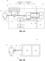
- FIG. 1A illustrates aspects of a generalized blood treatment system 100 that employs batch processing.
- the system 100 can include a primary module 104 and a treatment module 106.
- the primary module 104 can be designed to transfer blood to/from patient 102 and hold blood for processing.
- a vascular access 112 is coupled to a single-lumen I/O conduit 114 to provide blood from patient 102 to primary module 104 for processing.
- the vascular access 112 can comprise a needle, catheter, or any other device for connecting to the patient vascular system known in the art.
- the treatment module 106 can be designed to affect a treatment on blood passing thereto, for example, a dialysis treatment including hemofiltration (HF), hemodiafiltration (HDF), hemodialysis (HD), or hemoperfusion (HPF).
- HF hemofiltration
- HDF hemodiafiltration
- HPF hemoperfusion
- modules 104, 106 may be constructed as separate components and connected to each other by appropriate blood-compatible connectors.
- the primary module 104 may be a standalone system with releasable connectors that allow an installed treatment module 106 performing one type of blood treatment to be swapped out or switched for another treatment module performing another type of blood treatment.
- the swapping of treatment modules 106 installed in primary module 104 may be effective to renew or enhance a treatment component (e.g., an HPF device) expended in the blood processing.
- the system 100 may offer different blood or body fluid treatments by simply replacing the treatment module 106 installed to the primary module 104.
- system 100 may be considered to have an interfacing circuit 108 that conveys blood to/from patient 102 and a processing circuit 110 that treats the blood.
- the interfacing circuit 108 may be constituted by components fully or substantially contained in primary module 104, while the processing circuit 110 may be constituted by some components contained in primary module 104 and other components contained in treatment module 106.
- the interfacing circuit 108 can include, for example, single lumen I/O conduit 114, a first blood pump 116, and a fluid/drug module 118 with associated supply conduits 119, 126.
- the first pump 116 can be a Harvard apparatus or syringe pump or infuse/withdraw pump.
- the processing circuit 110 can include, for example, a blood reservoir or chamber 128, a second blood pump 132, a treatment device 130 (e.g., filtration device), and conduits 136, 138 that form a recirculation fluid circuit 140 between the reservoir 128 and treatment device 130.
- the second pump 132 can be a Harvard apparatus or syringe pump or infuse/withdraw pump.
- system 100 may also include a controller 142 operatively coupled to the various components of the interfacing 108 and processing 110 circuits for controlling operation thereof to effect batch processing and blood treatment.
- System 100 may also include an input/output (I/O) module 144, which can be operatively coupled to the controller 142.
- the I/O module 144 can be configured to convey control signals, data, or any other information to external systems, for example, to coordinate operation of system 100 with other treatment devices (e.g., as described below with respect to FIG. 3 ) or to convey a status of treatment to a local or remote monitoring system.
- the I/O module 144 can receive operating instructions from and/or provide information (e.g., visual or auditory) to a medical operator of the system 100 or the patient 102.
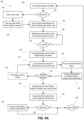
- the process 200 can initiate at 202 and proceed to 204, where it is determined if a secondary fluid or drug is to be added to the blood reservoir 128.
- controller 142 can determine if secondary fluid addition is required based on the type of treatment module 106, the type of blood treatment to be performed, and/or custom instructions received via I/O 144. For example, when treatment module 106 provides HDF, controller 142 can instruct the addition of hemofiltration or replacement fluid. Alternatively or additionally, the controller 142 can instruct the addition of a drug or a therapeutic agent.
- controller 142 can instruct the addition of an appropriate anticoagulant, such as heparin, citrate-based anticoagulants, nafamostat, or epoprostenol.
- an appropriate anticoagulant such as heparin, citrate-based anticoagulants, nafamostat, or epoprostenol.
- the process 200 can proceed to 206, where the secondary fluid and/or drug is flowed from secondary fluid supply 120 and/or anticoagulant supply 122 in fluid/drug module 118 to the blood reservoir 128.
- controller 142 can control fluid/drug module 118, first pump 116, and various valves or other fluid control components (not shown) to pump secondary fluid and/or anticoagulant from module 118 via one or more input conduits 119 to single-lumen conduit 114, and then on to blood reservoir 128.
- the process 200 can proceed to 208, where blood is withdrawn from patient 102 via access 112 and conveyed to reservoir 128 for temporary storage until treatment processing.
- controller 142 can control first pump 116 and various valves or other fluid control components (not shown) to pump the blood from patient 102 along single-lumen conduit 114 to the reservoir 128 at a first flow rate.
- the blood conveying 208 can continue via 210 until a predetermined blood volume (V) is obtained in the reservoir 128.
- the predetermined blood volume may be adjustable based on a size of patient 102, for example, 2-7% or 1-15% such as 1, 2, 3, 4, 5, 6, 7, 8, 9, 10, 11, 12, 13, 14 or 15% of a total blood volume of patient 102.
- the predetermined blood volume may be 10-300 ml, or 10 ml to 1000 ml and may be set by the patient 102 or system operator via I/O module 144.
- the controller 142 can monitor the volume of blood in reservoir 128 and determine at 210 whether the predetermined blood volume has been met. For example, a weight of reservoir 128 and contents therein can be monitored by a highly-accurate weight sensor 134, e.g., a gravity scale. Because the blood volume in reservoir 128 is relatively small (e.g., less than 300 ml), the reservoir 128 should be weighed very accurately to avoid incorrect volume correlations. For example, the weight sensor may have an accuracy down to 1 gram or less. Those of skill in the art will know of other sensors to measure fluid level including floats, gauges, capacitive level sensors, light sensors and other volume or weight sensors, which can be used.
- Controller 142 can then correlate changes in weight of reservoir 128 to changes in fluid/blood volume therein. Controller 142 can also correlate changes or the presence of a signal when other volume levels sensors are used.
- weight sensor 134 provides signals to controller 142 in real-time during fill of reservoir 128. The sensor 134 and/or controller 142 may thus be configured to compensate for any weight fluctuations due to fluid dynamics/vibration within the reservoir during the blood flow 208. Alternatively or additionally, controller 142 may sample signals from the weight sensor 134 and determine at 210 if sufficient volume has been achieved during intermittent pauses in flow 208 to allow blood in reservoir 128 to settle.
- fluid conveyances other than pump 116 can be used for the secondary fluid or anticoagulant.
- input conduit 119 of fluid/drug module 118 may bypass single-lumen conduit 114 and interface directly with the blood reservoir 128.
- a fluid conveyance (not shown) arranged between the fluid/drug module 118 and the reservoir 128 can transport the secondary fluid or anticoagulant to reservoir 128, such that secondary fluid/drug flow 206 may be able to occur simultaneously with supply 208 of blood to the reservoir 128.
- the fluid conveyance may be a fluid pump similar to pump 116, a Harvard apparatus, a syringe pump, a gravity-feed controlled by an appropriate valve, or any other device known in the art.
- controller 142 can control first pump 116 and various valves or other fluid control components (not shown) to stop the blood flow from patient 102 and to otherwise isolate single-lumen conduit 114 from blood reservoir 128 for subsequent treatment processing.
- the process 200 can thus proceed to 214, where blood treatment processing may initiate.
- blood from reservoir 128 (potentially with secondary fluid and/or anticoagulant) is conveyed at 214 to filtration device 130, where the blood is subjected to a treatment process at 216 (e.g., flowing through to effect a dialysis treatment), and then returned to the reservoir 128 at 218.
- controller 142 can control second pump 132 and various valves or other fluid control components (not shown) to flow blood from reservoir 128 along conduit 136, through filtration device 130, and back to reservoir 128 via conduit 138.
- the flowing of blood in each of 214-218 may be at a second flow rate.
- the second flow rate is greater than the first flow rate (used to withdraw blood from patient 102) to enhance solute clearance efficiency.
- the second flow rate can be 50-500 ml/min and may be at least 1.25 times, and preferably at least 2 times, greater than the first flow rate.
- the first and or third flow rate is about 5 ml/min to about 250 ml/min, or about 5 ml/min, 10 ml/min, 15 ml/min, 20 ml/min, 25 ml/min, 30 ml/min, 35 ml/min, 40 ml/min, 45 ml/min, 50 ml/min, 55 ml/min, 60 ml/min, 65 ml/min, 70 ml/min, 75 ml/min, 80 ml/min, 85 ml/min, 90 ml/min, 95 ml/min, 100 ml/min, 105 ml/min, 110 ml/min, 115 ml/min, 120 ml/min, 125 ml/min, 130 ml/min, 135 ml/min, 140 ml/min, 145 ml/min, 150 ml/min, 155 ml/min, 160
- the second flow rate is at least 1.25 times, and preferably at least 2 times, greater than the first flow rate or 50-750 ml/min, or about 50 ml/min, 55 ml/min, 60 ml/min, 65 ml/min, 70 ml/min, 75 ml/min, 80 ml/min, 85 ml/min, 90 ml/min, 95 ml/min, 100 ml/min, 105 ml/min, 110 ml/min, 115 ml/min, 120 ml/min, 125 ml/min, 130 ml/min, 135 ml/min, 140 ml/min, 145 ml/min, 150 ml/min, 155 ml/min, 160 ml/min, 165 ml/min, 170 ml/min, 175 ml/min, 180 ml/min, 185 ml/min, 190 ml/min, 195
- controller 142 can determine whether sufficient treatment has occurred based on an elapsed time of the processing, a magnitude of the second flow rate, and/or a volume of the blood batch in reservoir 128. If sufficient processing has not been achieved at 220, the process 200 can proceed to 222, where the blood is optionally recirculated and reprocessed by returning to 214.
- the flowing of blood along recirculation circuit 140 in 214-218 can be repeated such that each portion of the blood passes through filtration device 130 more than twice (e.g., 2-10 times), and preferably several times in an iterative process.
- the recirculation of blood may be such that the entire volume of the reservoir passes through the filtration device at least three times before being returned to the patient.
- the repeated processing of the same blood by the filtration device may achieve further improved clearance efficiency as compared to conventional single-pass RRT systems.
- controller 142 can correlate changes in weight of reservoir 128 (or other fluid level sensor as measured by sensor 134) to a stage of treatment processing. For example, an amount of fluid removed from the blood by the filtration device 130 can correlate with a stage of the treatment, which fluid removal can be detected in changes in instantaneous or average weight or level of fluid of reservoir 128 and contents therein.
- weight sensor 134 provides signals to controller 142 in real-time during flow of blood from/to reservoir 128.
- the sensor 134 and/or controller 142 may thus be configured to compensate for any weight fluctuations due to fluid dynamics/agitation within the reservoir during the blood flows 214-218.
- controller 142 may sample signals from the weight sensor 134 and determine at 220 if sufficient processing has been achieved during intermittent pauses in blood flows 214-218 to allow blood in reservoir 128 to settle.
- practice 214-222 may occur simultaneously, with blood recirculating between reservoir 128 and filtration device 130 continuously until sufficient processing has been achieved at 220.
- the continuous recirculation may be periodically interrupted, for example, to allow for a more accurate weight measurement or fluid volume level of blood or body fluid reservoir 128 by sensor 134.
- controller 142 can control first pump 116 and various valves or other fluid control components (not shown) to pump the blood from reservoir along single-lumen conduit 114 to the access 112 at a third flow rate. Since the blood return uses the same conduit 114 and access 112 as the blood withdrawal, the third flow rate can be, but does not need to be, the same as the first flow rate.
- the process 200 can then proceed to 228, where it is determined if a secondary fluid or drug is to be added to patient 102.
- controller 142 can instruct the addition of an appropriate anticoagulant reversal agent, such as protamine and/or calcium.
- controller 142 can determine if secondary fluid addition to patient 102 is required based on the type of treatment module 106, the type of blood treatment performed, and/or custom instructions received via I/O 144.
- controller 142 can instruct the infusion of a volume of replacement fluid such as albumin to patient 102.
- the controller 142 can determine at 228 to use secondary fluid (e.g., buffer or saline) from module 118 to flush conduit 114 and access 112 in preparation for a subsequent batch at 230.
- secondary fluid e.g., buffer or saline
- the process 200 can proceed to 226, where the secondary fluid and/or drug is flowed from secondary fluid supply 120 and/or anticoagulant reversal supply 124 in fluid/drug module 118 to the patient 102.
- controller 142 can control fluid/drug module 118, first pump 116, and various valves or other fluid control components (not shown) to pump secondary fluid and/or anticoagulant reversal agent from module 118 via one or more input conduits 126 to single-lumen conduit 114, and then on to patient 102.
- the process 200 can proceed to 230, where it is determined if another batch of blood for the same patient 102 should be processed.
- controller 142 can control system 100 to repeat process 200 for multiple sequential batches until an entire blood volume of the patient 102 has been processed (e.g., 4-6 liters of blood).
- controller 142 can control system 100 to repeat process 200 until a predetermined time limit or predetermined number of repetitions or volume of body fluid has been reached.
- I/O module 144 can be used by the patient 102 or operator to set the predetermined time limit or number of repetitions or volume of body fluid. If further batches are desired at 230, the process 200 returns to 204. Otherwise, the process 200 may terminate at 232 until initiated again for the same patient 102 or a different patient.
- Each blood batch processing cycle comprises a batch preparation stage (constituted by secondary fluid/drug flow 206 and blood withdrawal 208), a blood treatment stage (constituted by blood treatment 216), and a batch return stage (constituted by blood infusion 224 and secondary fluid/drug flow 226).
- the batch preparation and batch return stages can employ fluid flow rates less than that of blood treatment stage.
- the batch preparation stage and batch return stage employ fluid flow rates that are substantially the same.
- a time (t w ) for the batch preparation stage and a time (t i ) for the batch return stage may also be substantially the same. These times may be based on a volume of the blood batch, sizes of the vascular access 112 and single-lumen conduit 114, and fluid flow rate, among other things or metrics.
- a time (t bp ) for the blood treatment stage may be similar to that of the other stages despite the higher fluid flow rate.
- the time (t bp ) for the blood treatment stage may be greater than that for either or both of the other stages.
- the blood treatment stage time (t bp ) may be based on a volume of the blood batch, type of filtration device, fluid flow rate, and desired degree of recirculation (e.g., number of passes of blood through the filtration device), among other things or metrics.
- the time for each cycle is designed to be less than 10 minutes.
- the total time for each cycle may be 4-7 minutes, thereby enabling up to 15 cycles to be achieved in an hour.
- System 100 and/or process 200 can be adapted to provide various dialysis treatment therapies, including continuous RRT, periodic intermittent RRT, nocturnal dialysis, daily home dialysis, or any other dialysis or blood purification application.
- the use of batch processing by system 100 and/or process 200 advantageously allows a single-lumen conduit 114 to be used for both withdrawal of blood from patient 102 and later infusion of processed blood to patient 102, unlike conventional RRT systems where two lumens are used to simultaneously withdraw blood from and infuse processed blood to the patient. This single access point or port can ease the burden of vascular access in both acute and chronic patients.
- system 100 may employ needles or catheters having a size less than that typically used in conventional RRT systems, which smaller size (and reduced number) may be better tolerated (or at least less painful or intrusive) by patient 102.
- the decoupling of flow rates also allows a higher second flow rate to be used than would otherwise be possible with conventional RRT systems, thereby improving clearance, especially of middle molecules (e.g., 500 Daltons to 60 kD).
- middle-molecule clearance can be achieved using (1) a high-flux dialyzer, (2) high blood flow rates, and (3) high dialysate flow rates, the combination of which is difficult to achieve in conventional RRT systems but is readily provided by system 100.
- Middle-molecule clearance can be measured by a representative middle molecule such beta 2 microglobulin.
- middle molecule clearance as measured by beta 2 microglobulin of at least 25 ml/min, and preferably 80-130 ml/min, can be achieved.
- system 100 and/or process 200 can achieve a middle molecule clearance as measured by beta 2 microglobulin clearance greater than 100ml/min with a single-lumen access 114, e.g., a catheter smaller than 7 French or a needle smaller than 17 gauge.
- FIG. 1A shows a single vascular access 112
- system 100 can also be adapted to existing setups having a two-lumen connection to the vascular system (e.g., previously-installed multi-lumen catheter or central line).
- FIG. 1B illustrates a configuration where vascular access includes two lumens 152, 154 connected to the vascular system of patient 102.
- the lumens may be part of an installed multi-lumen catheter or may be separate needles inserted into the patient, e.g., at an arteriovenous fistula or graft.
- a fluidic union 156 (e.g., Y-connector) is provided between the patient 102 and system 100 in order to couple the separate lumens 152, 154 to the single-lumen conduit 114 of system 100.
- system 100 is still capable of withdrawing/infusing blood using a single-lumen (i.e., conduit 114) despite the multi-lumen vascular access.
- System 100 and/or process 200 may further exhibit one or more of the following advantages:
- blood batches can be small (e.g., ⁇ 300ml) and anticoagulated, and therefore a smaller capacity filtration device (e.g., hemofilter) can be utilized for the treatment processing.
- a smaller capacity filtration device e.g., hemofilter
- the smaller components may reduce system costs.
- the smaller filtration device coupled with relatively small batch volume can yield a footprint and/or three-dimensional size that is less than conventional RRT systems.
- the overall extracorporeal blood treatment system may thus be substantially portable, or at least more so than conventional RRT systems.
- blood batches can be small, and therefore an effective amount of anticoagulant may be used that is less than that required for conventional RRT systems.
- the anticoagulant may be localized (e.g., within system 100 and at the infusion site in the patient) rather than being distributed through the vascular system, which may avoid patient complications. Any anticoagulant infused into the patient may also be reversed by delivery of an anticoagulant reversal agent by the system.
- blood is only processed in batches, and therefore the risk of a blood leak in processing circuit 110 causing significant blood loss is mitigated. Moreover, since the first flow rate for blood withdrawal is relatively slower, the risk of significant blood loss due to a blood leak in the interfacing circuit 108 is also reduced.
- batch size, flow rates, and/or processing time can all be customized, for example, to take into account patient size or illness severity. Smaller withdrawal volumes of blood may decrease hemodynamic instabilities often seen when a conventional RRT session is initiated. System 100 and/or process 200 (and/or any of the subsequently discussed embodiments) may exhibit additional or different advantages or features beyond those specifically delineated above.
- the methods and systems disclosed can be used to process other body fluids.
- accumulation of fluid in the abdominal cavity is called ascites.
- Ascites can be common with patients with cirrhosis, liver disease or congestive heart failure.
- a diuretic can also be administered.
- Commonly used diuretics include spironolactone (Aldactone) and/or furosemide (Lasix).
- Aldactone spironolactone
- Lasix furosemide
- the disclosure includes methods and systems for treating ascites, by the withdrawal of ascites.
- the withdrawn ascitic fluid can be concentrated and reinfused.
- Paracentesis is carried out under strict sterile conditions. Ascites is withdrawn from patient 102 via access 112 and conveyed to reservoir 128 for temporary storage until treatment processing.
- Pump 116 can be used to remove the ascitic fluid at a flow rate of from about 50 ml/min to about 200 ml/min such as about 100 ml/min to about 150 ml/min. Alternatively, ascitic fluid removal may use gravity.
- the needle is usually inserted into the left or right lower abdomen, where the needle is advanced through the subcutaneous tissue and then through the peritoneal cavity. In certain aspects, the ascitic fluid is drained in a single session, assisted by gentle mobilization of the cannula or turning patient 102 if necessary.
- the body fluid (e.g., ascites) from reservoir 128 is conveyed to filtration device 130, where the ascites is subjected to a treatment process such as concentration and is thereafter returned to the reservoir 128.
- the concentrated ascites e.g., a protein rich concentrate
- Albumin may also be infused in lieu of the concentrated ascites, or in addition to the concentrated ascites.
- system 100 can be combined with another medical treatment device coupled to the same vascular access.
- FIG. 3 illustrates a system 300 that provides both fluid/drug infusion and blood treatment in a single setup.
- Medical treatment device 302 e.g. infusion pump
- a fluidic coupling 308 e.g., union connection, such as a Y-connector
- a fluidic coupling 308 can connect the single lumen conduit 114 of system 100 to an infusion supply line 306 of medical treatment device 302.
- system 300 may be realized by providing system 100 separate from an existing infusion device 302 and operatively connecting the two together, for example, via fluidic coupling 308 and electrical signal coupling 310 (e.g., communication line).
- system 300 may be realized as a single integrated machine, where fluidic coupling 308 and electrical signal coupling 310 are internal to the machine.
- the medical treatment device 302 can have a pump that infuses a fluid or drug from supply 304 into patient 102 via supply line 306, fluidic coupling 308, and vascular access 112.
- medical treatment device 302 and system 100 may send electrical signals over electrical signal coupling 310, which may be a physical wired connection and/or a wireless connection.
- electrical signal coupling 310 may be a physical wired connection and/or a wireless connection.
- the pump of medical treatment device 302 may pause infusion at least when blood is withdrawn from patient 102 by system 100. Medical treatment device 302 may otherwise continue infusion when blood is being processed by system 100 and/or when blood is being returned from system 100 to patient 102.
- an access valve 312 can be used to cut-off system 100 from conduit 114, such that fluid/drugs from device 302 does not enter system 100.
- fluidic coupling 308 and access valve 312 may be integrated together as a single component, e.g., a fluid switch, such that only one of system 100 and medical treatment device 302 are operatively connected to vascular access 112 at a time.
- FIGS. 3 and 4A an exemplary process 400 for operation of system 300 will be described.
- the operation of system 100 within the context of process 400 may be substantially similar to that described above with respect to process 200.
- FIG. 4A employs the same reference numbers as FIG. 2A for those operations and are not separately discussed here. Rather, the discussion below focuses on the differences of process 400 from process 200.
- the process 400 can initiate at 402, where fluid or a drug from supply 304 is infused via vascular access 112 into patient 102 using medical treatment device 302.
- the medical treatment device 302 has its own independent control system that dictates operation of infusion 402 (e.g., based on input by patient 102 or an operator).
- the medical treatment device 302 receives instructions from controller 142 of system 100, for example, via electrical signal coupling 310.
- Infusion 402 can continue until system 100 requires use of the vascular access 112 for blood withdrawal.
- the process 400 can determine if secondary fluid/drug should be added to reservoir 128 to begin a blood batch treatment cycle.
- process 400 can optionally close access valve 312 (if not already closed) to ensure that the secondary fluid/drug only travels to reservoir 128 rather than to patient 102.
- the process 400 can proceed to 406, where infusion by medical treatment device 302 is temporarily paused to allow blood to be withdrawn at 208 from patient 102 via access 112 and conveyed to reservoir 128.
- 406 can optionally include opening access valve 312 to allow blood to flow from vascular access 112 into system 100 via single-lumen conduit 114.
- the infusion pause 406 and blood withdrawal 208 may continue until a predetermined blood volume in reservoir 128 has been achieved at 210, after which process 400 can proceed to 408, where blood withdrawal is terminated and infusion by medical treatment device 302 is resumed.
- the blood processing 214-218 and recirculation 222 can occur simultaneously with resumed infusion 408.
- the process 400 can proceed in a manner similar to process 200, for example, by returning blood 224, flowing secondary fluid and/or anticoagulant reversal agent 226, and repeating at 230 for a subsequent batch.
- 224 can optionally include opening access valve 312 to allow blood to flow from system 100 to vascular access 112 via single-lumen conduit 114.
- the blood return 224 by system 100 may occur simultaneously with fluid/drug infusion 408 by medical treatment device 302.
- the blood flow rate and/or the fluid/drug infusion flow rate may be adjusted during this stage to accommodate the two simultaneous flows via the single-lumen conduit 114 and/or vascular access 112.
- process 400 can optionally pause infusion by medical treatment device 302 at 410, thereby allowing blood return 224 and/or secondary fluid/reversal agent flow 226 to have sole access to conduit 114 and vascular access 112.
- 410 can optionally include opening access valve 312 to allow blood to flow from system 100 to vascular access 112 via single-lumen conduit 114.
- FIG. 4B shows a time map 450 corresponding to the process 400 of FIG. 4A .
- timing of system 100 within the context of map 450 is substantially similar to that described above with respect to time map 250. Accordingly, FIG. 4B employs the same reference numbers as FIG. 2B for that timing, which will not be separately discussed here.
- FIG. 4B illustrates possible infusion periods with respect the blood batch processing cycle. For example, an initial period 452 by medical treatment device 302 can occur before the first blood processing cycle and may overlap with at least the secondary fluid/drug flow 206 of the batch preparation stage of the blood processing cycle. Infusion may then be paused during blood withdrawal 208 of each batch preparation stage, and then resume at 454 during each blood treatment stage (constituted by blood treatment 216).
- infusion by medical treatment device 302 may again be paused during each batch return stage (constituted by blood infusion 224 and secondary fluid/drug flow 226) to allow system 100 sole access to vascular access 112.
- infusion 458 by medical treatment device 302 may optionally continue during each batch return stage.
- the rate of infusion 458 may be reduced as compared to infusion 454 during the blood treatment stage to accommodate the additional flow of blood from system 100 to the vascular access.
- the infusion may optionally resume (or increase to its nominal rate) for a period 456 during the secondary fluid/drug flow 206 of the next batch preparation stage.
- extracorporeal blood treatment systems and methods can utilize more than one blood reservoir for serial or parallel treatment processing.
- FIG. 5A shows a simplified layout for a generic extracorporeal blood treatment system 500 utilizing a pair of blood reservoirs 128a, 128b providing serial blood treatment processing.
- System 500 includes an interfacing circuit 510 and a pair of processing circuits 512a, 512b.
- Each processing circuit 512a, 512b can have respective blood reservoirs 128a, 128b, weight or fluid level sensors 134a, 134b, blood pumps 132a, 132b, which may be Harvard apparatuses and filtration devices 130a, 130b.
- Each processing circuit 512a, 512b is thus substantially similar to processing circuit 110 of FIG. 1A and may operate independently of each other to effect a blood treatment in a similar manner to processing circuit 110.
- the interfacing circuit 510 is substantially similar to interfacing circuit 108 of FIG. 1A and thus may operate in a similar manner to interfacing circuit 108.
- interfacing circuit 510 further includes a fluid switch 502 (or combination of valves or other flow control devices to provide the effect of a switch) that connects single lumen conduit 114 to either an inlet conduit 504 of first processing circuit 512a or an inlet conduit 506 of second processing circuit 512b. Since only one processing circuit 512a, 512b can be connected to single lumen conduit 114 by switch 502 at a time, processing circuits 512a, 512b may be considered to operate serially.
- switch 502 selects for processing circuit 512a, such that blood or body fluid from patient 102 can be conveyed to reservoir 128a or processed blood from reservoir 128a can be returned to patient 102 via single lumen conduit 114 and inlet conduit 504.
- processing circuit 512b is de-selected by switch 502. While de-selected, processing circuit 512b may recirculate previously withdrawn blood between reservoir 128b and filtration device 130b to effect a blood treatment.
- blood treatment processing by one of the processing circuits 512a, 512b may occur while the other of the processing circuits 512a, 512b is withdrawing or infusing blood, thereby taking advantage of what would otherwise be considered blood processing downtime in a single blood reservoir system.
- processing circuit 512b may be idle during the de-selected period. Similar to control system 142, control system 508 controls operation of components of the interfacing circuit 510 (for example, selection by switch 502) and processing circuits 512a, 512b.
- control system 508 controls operation of components of the interfacing circuit 510 (for example, selection by switch 502) and processing circuits 512a, 512b.
- additional processing circuit(s) are possible such as 512c, 512d, etc., by including additional switches.
- FIG. 5B shows a simplified layout for a generic extracorporeal blood treatment system 550 utilizing a pair of blood reservoirs 128a, 128b providing parallel blood treatment processing.
- System 550 includes an interfacing circuit 552 and a pair of processing circuits 512a, 512b, each of which is substantially similar to processing circuit 110 of FIG. 1A and may operate independent of each other to effect a blood treatment in a similar manner to processing circuit 110.
- the interfacing circuit 552 is similar to interfacing circuit 510 of FIG. 5A but includes a fluidic union 554 (or combination of valves or other flow control devices to provide the effect of a union) instead of a switch 502.
- the union 554 e.g., a Y-connector
- One of skill in the art will recognize that one or more additional processing circuit(s) are possible such as 512c, 512d, etc., by including additional unions.
- blood from patient 102 can be simultaneously conveyed to reservoirs 128a, 128b or processed blood from reservoirs 128a, 128b can be simultaneously returned to patient 102 via single lumen conduit 114 and inlet conduits 504, 506.
- the blood volume from the patient 102 traveling along single lumen conduit 114 can be split between each of the blood reservoirs 128a, 128b, and blood returning from reservoirs 128a, 128b can be combined prior to introduction to patient at vascular access 112.
- Processing circuits 512a, 512b may also recirculate blood between reservoirs 128a, 128b and filtration devices 130a, 130b at the same time to effect a parallel blood treatment. Similar to control system 142, control system 508 controls operation of components of interfacing circuit 552 and processing circuits 512a, 512b.
- processing circuits 512a, 512b are illustrated as being identical in FIGS. 5A-5B , in some embodiments, filtration devices 130a, 130b may be different (i.e., offering separate treatment modalities). For example, a first fraction of the withdrawn blood is subjected to a first treatment modality by processing circuit 512a while a second fraction of the withdrawn blood is subjected to a second treatment modality (which may be different or complementary to the first treatment modality or regimens) by processing circuit 512b.
- FIGS. 5A-5B illustrate exemplary systems with a pair of blood reservoirs, serial or parallel processing with additional blood reservoirs is also possible according to one or more contemplated embodiments. Indeed, the teachings of FIGS.
- 5A-5B can be readily extended to three or more blood reservoirs (and associated processing circuits) by appropriate design of switching (e.g., switch 502) or union (e.g., union 554) components.
- switching e.g., switch 502
- union e.g., union 554
- a combination of serial and parallel processing circuits are contemplated.
- HDF hemodiafiltration
- HDF is a form of renal replacement therapy that utilizes convective clearance in combination with diffusive clearance.
- HDF removes more middle-molecular-weight solutes.
- HDF system 600 can have a single-lumen conduit 606 connected to a single-lumen vascular access 604 coupled to the vascular system of patient 102.
- the vascular access 604 can be a needle or catheter having size smaller than either 17 gauge or 7 French.
- a reversible blood pump 626 (e.g., pulsatile blood pump, peristaltic roller pump, withdrawal/infusion, etc.) is used to convey fluids along single-lumen conduit 606, e.g., blood to/from patient 102 and reservoir 634 or other fluids via supply lines 614, 629, 659, 661.
- One or more sensors can be disposed along the flow path of the single-lumen conduit 606.
- an air detector 608 can be disposed along the conduit 606 proximal to the vascular access 604 (viewed right to left) to detect any air that may be introduced into system 600 during the withdrawal for safety purposes.
- a pressure gauge 609 can also be provided along conduit 606 proximal to vascular access 604 to detect pressure changes during blood withdrawal or infusion, which changes may indicate, for example, decoupling of the vascular access 604 from the patient 102 or a blockage of the vascular access 604 or elsewhere along conduit 606.
- One or more flow control devices can be disposed along the flow path of the single-lumen conduit 606.
- a first valve 610 can be arranged along conduit 606 between the vascular access 604 and blood pump 626.
- first valve 610 may be located between connection points at conduit 606 for supply lines 614, 659 and the vascular access 604, so as to isolate the vascular access 604 when fluid is introduced to conduit 606 via these supply lines.
- a second valve 632 can be arranged along conduit 606 between blood pump 626 and blood chamber or reservoir 634, for example, to isolate the blood reservoir 634 from conduit 606 during blood processing.
- second valve 632 may be located between connection points at conduit 606 for supply lines 629, 661 and blood reservoir 634, so as to isolate the reservoir 634 when fluid is introduced to conduit 606 via these supply lines.
- a supply 616 of hemofiltration (HF) fluid can be connected to supply lines 614 and 661, each of which may have a respective flow control device.
- HF supply lines 614, 661 can have a third valve 612 and fourth valve 624, respectively, that opens/closes respective flow paths between the HF supply 616 and conduit 606.
- a heater 622 can heat HF fluid flowing along supply line 661 to ensure a temperature of HF fluid is appropriate for infusion into patient 102.
- a supply 620 of anticoagulant e.g., heparin, citrate-based anticoagulants, nafamostat, epoprostenol, etc.
- a supply 630 of anticoagulant reversal agent e.g., protamine, calcium, etc.
- supply lines 659, 629 can have a fifth valve 618 and a sixth valve 628, respectively, that opens/closes respective flow paths between supplies 620, 630 and conduit 606.
- connection point at conduit 606 for anticoagulant supply line 659 may be between the blood pump 626 and the connection point at conduit 606 for HF supply line 614, while the connection point at conduit 606 for ARA supply line 629 may be between the blood pump 626 and the connection point at conduit 606 for HF supply line 661.
- the components arranged between and including the vascular access 604 and the second valve 632 may be considered an interfacing circuit of system 600.
- the remaining components of system 600 illustrated in FIG. 6A may be considered a processing circuit of system 600.
- Blood reservoir 634 can have a first fluid port coupled to single lumen conduit 606, with access between the first fluid port and conduit 606 controlled by second valve 632. Blood reservoir 634 can also have a second fluid port coupled to recirculating supply line 638, with access between the second fluid port and supply line 638 controlled by a seventh valve 636. Blood reservoir 634 can also have a third fluid port coupled to recirculating return line 646, with access between the third fluid port and return line 646 controlled by an eighth valve 648. Although shown separate from blood reservoir 634, valves 632, 636, 648 (or other flow control components) may form part of the reservoir 634 itself in some embodiments.
- valves for the blood reservoir 634 can be combined together or replaced by a common fluid control component providing similar functions, for example, where second valve 632 and seventh valve 636 are replaced by a fluidic switch that connects a fluid port of the blood reservoir to either conduit 606 or to recirculating supply line 638.
- a blood pump 640 (e.g., pulsatile blood pump, peristaltic roller pump, Harvard apparatus, syringe pump, etc.) is used to convey fluids from reservoir 634 to dialyzer 644 (e.g., cross-flow dialyzer) via recirculating supply line 638 and from dialyzer 644 back to reservoir 634 via recirculating return line 646.
- dialyzer 644 e.g., cross-flow dialyzer
- recirculating return line 646 is no longer needed as conduit 630 is used to recirculate the fluid between blood reservoir 634 and dialyzer 644.
- a dialysate pump 652 (e.g., peristaltic pump, positive displacement pump, centrifugal pump, Harvard apparatus, syringe pump, etc.) is used to convey dialysate from a supply 656 to dialyzer 644, where the dialysate flows through a chamber of the dialyzer 644 separated by a membrane or filter from a chamber of the dialyzer 644 in which the blood flows.
- a heater 654 can heat dialysate flowing to dialyzer to ensure a temperature of dialysate compatible with the blood in reservoir 634.
- a separate pump 662 e.g., peristaltic pump, positive displacement pump, centrifugal pump, etc.
- effluent e.g., ultrafiltration fluid, removed solutes, and spent dialysate
- waste 658 e.g., a waste container, drain, or other medical disposal.
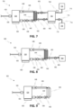
- dialysate pump 652 can pump dialysate from and effluent pump 662 can pump fluid to a common dialysate reservoir 702, for example, to provide recirculation of dialysate as shown in FIG. 7 .
- FIG. 7 only shows the components of the processing circuit 700, as the system components connected at the left end of conduit 606 would otherwise be the same as FIG. 6A .
- a drain pump 712 can be connected to the common dialysate reservoir 702 to remove spent dialysate therefrom during or after processing, for example, by conveying spent dialysate to waste 706 via conduit 714.
- Dialysate supply 704 may thus be connected to the common dialysate reservoir 702 to provide fresh dialysate thereto during or before processing.
- a heater 708 may be supplied along dialysate supply line 710 for heating the fresh dialysate supplied to the reservoir 702.
- a weight sensor 716 similar to weigh sensor 650, or volume level sensor may be used to monitor a volume of fluid within dialysate reservoir 702.
- one or more sensors can be disposed along the flow paths to/from dialyzer 644.
- pressure gauge 642 can be disposed along conduit 638 distal to a blood inlet of dialyzer 644 (viewed right to left) to detect pressure changes during HDF processing, which changes may indicate, for example, a blockage of the dialyzer 644 or a blockage elsewhere along conduits 638, 646.
- a blood leak detector 660 e.g., optical detector
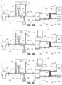
- system 600 provides a volume of anticoagulant 664 to the blood reservoir 634, as shown in FIG. 6B .
- fifth valve 618 and second valve 632 may be opened while the remaining valves 610, 612, 624, 628, 636, and 648 are closed.
- Pump 626 can operate in a first direction to convey the anticoagulant 664 from supply 620 along conduits 659 and 606 into reservoir 634.
- the volume to be added to reservoir 634 may be 5-200 units of heparin per 100 ml of blood. If patient 102 has already been anticoagulated (i.e., by intravenous delivery of an appropriate anticoagulant), the system may skip providing anticoagulant 644 and instead proceed directly to the configuration of FIG. 6C .
- the system 600 After addition of anticoagulant 644 in FIG. 6B , the system 600 provides a volume of HF fluid 666 to the blood reservoir, as shown in FIG. 6C .
- third valve 612 and second valve 632 may be opened while the remaining valves 610, 618, 624, 628, 636, and 648 are closed.
- Pump 626 can operate in the first direction to convey the HF fluid 666 from supply 616 along conduits 614 and 606 into reservoir 634.
- the volume of HF fluid 666 may be determined based on the volume of blood to be added to reservoir 634 and the expected volume of ultrafiltrate generated during processing.
- the system 600 withdraws a volume of blood 668 from the patient 102 and adds it to blood reservoir 634, as shown in FIG. 6D .
- first valve 610 and second valve 632 may be opened while the remaining valves 612, 618, 624, 628, 636, and 648 are closed.
- Pump 626 can operate in the first direction to convey blood from the patient 102 via vascular access 604 along conduit 606 into reservoir 634.
- the volume of blood 668 may be determined based on the total blood volume of the patient, available capacity of the reservoir 634, a timing of each processing cycle, and/or maximum withdrawal flow rates based on size of vascular access 604 and/or size of conduit 606.
- the volume of blood 668 may be 10-300 ml or 2-7% of the total blood volume of patient 102.
- Weight sensor or other volume level sensor 650 which may have an accuracy of 1 gram or better or 1 ml or better, can be used to monitor a volume of the blood that has been added to reservoir 634.
- FIGS. 6B-6D show fluid volumes 664, 666, and 668 as being a lamination of volumes for illustration and discussion purposes only. In practical implementations, the anticoagulant, HF fluid, and blood would all mix together within reservoir 634 to provide a single mixed volume or an admixture, for example, as illustrated by 670 in FIG. 6E .
- FIG. 6E illustrates system 600 at the start of treatment processing, where the initial blood/HF fluid/anticoagulant mixture 670 is circulated through dialyzer 644 to yield processed blood 672.
- seventh valve 636 and eighth valve 648 may be opened while the remaining valves 610, 612, 618, 624, 628, and 632 are closed.
- Pump 640 can convey the blood mixture 670 from reservoir 634 along recirculation supply line 638 to and through dialyzer 644 and then back to reservoir 634 along recirculation return line 646.
- the flow rate provided by pump 640 may be 50-500 ml/min or more (e.g., 750 ml/min).
- dialysate pump 652 can convey dialysate from supply 656 to dialyzer 644 and an effluent pump 662 can withdraw effluent from dialyzer 644 to waste 658.
- Pump 640 can convey the blood mixture 670 at a flow rate that is greater, for example, at least 1.25 times greater, than a withdrawal rate of the blood from patient in FIG. 6C .
- the withdrawal rate may be less than 200 ml/min, such as 100-150 ml/min, while the flow rate provided by pump 640 in FIG. 6E may be at least 300 ml/min.
- Dialysate pump 652 and/or effluent pump 662 can generate a flow rate of dialysate through dialyzer 644 that is equal to or greater than the flow rate of the blood mixture 670 through the dialyzer 644.
- the flow rate of dialysate through dialyzer 644 may be at least 500 ml/min, or 500 ml to 1500 ml/min.
- the recirculation of blood 670 between reservoir 634 and dialyzer 644 in FIG. 6E may continue until an appropriate stop or end condition is reached.
- weight sensor or volume level sensor 650 can monitor a weight or volume of fluid within reservoir 634 (e.g., dynamically during recirculation or during intermittent pauses in recirculation) to determine when sufficient waste fluid has been removed by the dialyzer 644.
- recirculation may continue for a predetermined time or until blood 670 has passed through the dialyzer 644 for a predetermined number of times. For example, for a 300 ml initial blood volume, recirculation may continue for less than or equal to 3 minutes or until the entire initial blood volume has passed through the dialyzer 644 at least three times.
- system 600 takes advantage of the decoupling of blood processing flow rate from blood withdrawal flow rate to allow for a singular vascular access of smaller size than conventional RRT systems while achieving treatment performance comparable to or even better than conventional RRT systems.
- system 600 may shift to the blood return stage of the treatment cycle.
- FIG. 6F illustrates system 600 at the end of treatment processing, where the final processed blood 674 after recirculation awaits in blood chamber 634 for infusion to patient 102.
- valves 636, 648 may be closed and pump 640 stopped to terminate recirculation.
- Dialysate pump 652 and effluent 662 may also be stopped at the same time, or a short time thereafter.
- Other valves may also be closed, for example, to allow blood 674 to temporarily settle to provide an accurate weight measurement by sensor 650 prior to infusion.
- the system 600 infuses the processed blood 674 from reservoir 634 back to patient 102.
- first valve 610 and second valve 632 may be opened while the remaining valves 612, 618, 624, 628, 636, and 648 are closed.
- Pump 626 can operate in a second direction (opposite to the first direction) to convey processed blood 674 along conduit 606 from reservoir 634 to patient 102 via vascular access 604.
- pump 626 may infuse the processed blood 674 at a flow rate that is the same or substantially the same as the previous withdrawal rate in FIG. 6C .
- the infusion rate may be less than 200 ml/min, such as 100-150 ml/min or 25 ml/min, 50 ml/min, 100 ml/min, or 150 ml/min.
- the system 600 can infuse a volume of ARA 676 into patient 102, as shown in FIG. 6H .
- first valve 610 and sixth valve 628 may be opened while the remaining valves 612, 618, 624, 632, 636, and 648 are closed.
- Pump 626 can operate in the second direction to convey ARA 676 from ARA supply 630 along conduits 629, 606 and into patient 102 via vascular access 604.
- the volume of ARA 676 may be determined based on the processed blood volume 674 returned to the patient, the amount of anticoagulant added at FIG. 6B , and/or the type of ARA and anticoagulant.
- the system 600 can infuse a volume of HF fluid 678 into patient 102, as shown in FIG. 6I .
- first valve 610 and fourth valve 624 may be opened while the remaining valves 612, 618, 628, 632, 636, and 648 are closed.
- Pump 626 can operate in the second direction to convey the HF fluid from HF supply 616 along conduits 661, 606 and into patient 102 via vascular access 604.
- the infusion of HF fluid 678 may be effective to flush conduit 606 in preparation for the next batch processing cycle.
- the system can return to the configuration of FIG. 6B to process the next blood batch from patient 102 or may otherwise terminate if no further batches are desired.
- system 600 may also provide a hemodialysis (HD) treatment process.
- a flushing fluid such as normal saline (NS), etc.
- the volume of flushing fluid may be less than that of HF fluid used at FIGS. 6C , 6I .
- the volume of flushing fluid may be just enough to clear conduit 606 of any prior flows of anticoagulant (at FIG. 6B ) or ARA (at FIG. 6H ).
- the blood flow rate through dialyzer 644 may be less than that at FIG. 6E in the HDF treatment setup.
- the type of dialyzer may also be different from dialyzer 644 in the HDF treatment setup.
- the configuration and operation of system 600 to provide an HD treatment would otherwise be similar to that illustrated in FIGS. 6A-6I .
- processing circuit 800 removes the dialysate pump 652, heater 654, and dialysate supply 656 from the setup of system 600, instead relying on drain pump 806 to pull waste effluent from dialyzer 644 along drain line 802 to waste 804. Operation of processing circuit 800 may otherwise be substantially the same as that illustrated in FIGS. 6A-6I .
- the HDF system 600 of FIG. 6A-6I can be modified to provide an HPF treatment, as illustrated in FIG. 9 .
- FIG. 9 only shows the components of the processing circuit 900, as the system components connected at the left end of conduit 606 would otherwise be the same as FIG. 6A .
- processing circuit 900 of the HPF system replaces dialyzer 644 of HDF system 600 with an HPF cartridge or device 902. Since HPF relies on absorption of waste products to particles rather than diffusion or convection across a membrane into flowing dialysate, the processing circuit 900 of the HPF system also removes all components related to dialysate flow from the setup of FIG.
- processing circuit 900 may otherwise be substantially the same as that illustrated in FIGS. 6A-6I .
- the filter or filtration device can be for example, an extracorporeal hemoadsorption filter device to remove cytokines from circulating blood such as a biocompatible, sorbent bead technology e.g., CytoSorb TM , CytoSorbents TM , Inc.
- CytoSorb hemoadsorption beads are polystyrene-divinylbenzene porous particles (450 ⁇ m avg. particle diameter, 0.8-5 nm pore diameter, 850 m 2 /g surface area) with a biocompatible polyvinyl-pyrrolidone coating. See for example, US Patent No. 8,647,666 which claims a method of using a composition comprising polystyrene divinyl benzene copolymer and a polyvinyl pyrrolidone polymer.
- the filter or filtration device is Seraph ® Microbind ® Affinity Blood Filter from ExThera Medical Corp., which is a filter that allows body fluids to pass over microbeads coated with molecular receptor sites that mimic the receptors on human cells which pathogens use to colonize when they invade the body.
- the adsorption media is a flexible platform that uses covalently-bonded, immobilized heparin or heparan sulfate for its unique binding capacity. See, for example, US Patent Nos. 8,758,286 or 9,173,989 , disclosing at least one polysaccharide adsorbent, or immobilized heparin.
- a standard double-lumen dialysis catheter of 11 Fr (each lumen of 5-5.5 Fr) can run a blood flow rate (Qb) of 200-300 ml/min.
- Qb blood flow rate
- a single lumen catheter of at least 5 Fr can easily allow batches of 200-250 ml to be drawn into the SLAMB in 1 minute and returned in 1 minute.
- Single pass urea clearance in hemodialysis ranges between 85-90%, thus a batch of 200-250 ml can then be (re)cycled at 200-400 ml/min within the reservoir for 2-3 minutes to achieve 90-95% clearance (See, Macias et al., Clin Kidney J, 12: 447-455, 2019 ).
- a 75 kg patient dosed with a SLAMB prescription of 200 ml batch, 5-minute cycle time, 0 ml of ultrafiltrate would achieve a Kt/V of 0.8 in 14.8 hours. If smaller/longer intravenous access where utilized thus extending the cycle time, the time to achieve a Kt/V would be extended. In this example, if the ingress/egress of blood from the device were extended to 9 minutes (3 minutes cycling, 3 minutes for ingress and 3 minutes for egress) a catheter would need to perform a Qb flow of at least 67 ml/min and a Kt/V of 0.8 is achieved in 24 hours.
- the SLAMB system includes additional embodiments.
- the SLAMB system can be used to infuse blood products into a patient. This is direct infusion of blood, platelets, and other blood products or blood-like components into a patient. These are blood products properly screened, which do not need to be further processed with hemoperfusion.
- the SLAMB system can be used to process freshly donated blood and infuse the blood into a patient. This allows for emergency transfusions where prescreened whole blood is not available (i.e. battlefield scenarios, austere environments, mass casualty situations.) In these scenarios, the 'walking blood bag' or donor donates fresh blood. The blood is then processed through filtration (e.g., a Seraph ® cartridge from ExThera Medical, Martinez California; http://www.extheramedical.com/exthera-seraph) to reduce potential pathogens prior to infusion into a patient.
- filtration e.g., a Seraph ® cartridge from ExThera Medical, Martinez California; http://www.extheramedical.com/exthera-seraph
- the SLAMB system can further include adding the ability to provide IV fluids and IV drugs. If the pump is hooked up to a central line that is normally used for injecting fluids or drugs, the pump will still allow for the infusion of these products during use.
- a SLAMB-HDF allow RRT to be conducted with a single and small vascular access.
- Systems based on this design are simpler than current RRT systems which make them less expensive, lighter, and more portable thus increasing the options for patients who require RRT.
- control systems 142, 508, the input/output 144, the control of the systems illustrated in FIGS. 6A-9 , and/or processes 200, 400 can be implemented, fully or partially, in hardware, hardware programmed by software, software instruction stored on a computer readable medium (e.g., a non-transitory computer readable medium), or any combination of the above.
- a computer readable medium e.g., a non-transitory computer readable medium
- components of the disclosed subject matter can include a personal computer or workstation or other such computing system that includes a processor, microprocessor, microcontroller device, or is comprised of control logic including integrated circuits such as, for example, an application specific integrated circuit (ASIC).
- ASIC application specific integrated circuit
- aspects of the disclosed subject matter can be implemented via a programmed general purpose computer, an integrated circuit device, (e.g., ASIC), a digital signal processor (DSP), an electronic device programmed with microcode (e.g., a microprocessor or microcontroller), a hard-wired electronic or logic circuit, a programmable logic circuit (e.g., programmable logic device (PLD), programmable logic array (PLA), field-programmable gate array (FPGA), programmable array logic (PAL)), software stored on a computer-readable medium or signal, an optical computing device, a networked system of electronic and/or optical devices, a special purpose computing device, a semiconductor chip, a software module or object stored on a computer-readable medium or signal.
- a programmed general purpose computer e.g., an integrated circuit device, (e.g., ASIC), a digital signal processor (DSP), an electronic device programmed with microcode (e.g., a microprocessor or microcontroller), a hard-wired
- a computer-readable medium e.g., a non-transitory computer readable medium
- a computer memory or storage device which can be any suitable memory apparatus, such as read-only memory (ROM), programmable read-only memory (PROM), electrically erasable programmable read-only memory (EEPROM), random-access memory (RAM), flash memory, disk drive, etc.
- ROM read-only memory
- PROM programmable read-only memory
- EEPROM electrically erasable programmable read-only memory
- RAM random-access memory
- flash memory disk drive, etc.
- any connection is properly termed a computer-readable medium.
- a transmission medium e.g., coaxial cable, fiber optic cable, twisted pair, digital subscriber line (DSL), or wireless technologies such as infrared, radio, and microwave
- the transmission medium is included in the definition of computer-readable medium.
- the operations of a method or algorithm may reside as one of (or any combination of) or a set of codes and/or instructions on a machine-readable medium and/or computer-readable medium, which may be incorporated into a computer program product.
Landscapes
- Health & Medical Sciences (AREA)
- Heart & Thoracic Surgery (AREA)
- Vascular Medicine (AREA)
- Engineering & Computer Science (AREA)
- Anesthesiology (AREA)
- Biomedical Technology (AREA)
- Hematology (AREA)
- Life Sciences & Earth Sciences (AREA)
- Animal Behavior & Ethology (AREA)
- General Health & Medical Sciences (AREA)
- Public Health (AREA)
- Veterinary Medicine (AREA)
- Cardiology (AREA)
- Urology & Nephrology (AREA)
- Emergency Medicine (AREA)
- External Artificial Organs (AREA)
Claims (15)
- Blutbehandlungssystem (100), umfassend eine Fluidverarbeitungsschaltung (110) mit einem Reservoir (128), einer ersten Blutpumpe (132), einer zweiten Blutpumpe (116), einer Filtrationsvorrichtung (130) und einer Steuerung (142), die dazu ausgelegt ist, den Betrieb der ersten (132) und der zweiten Blutpumpe (116) beim Durchführen einer extrakorporalen Behandlung an einer Blutcharge eines Patienten (102) zu steuern,
dadurch gekennzeichnet, dassein Einlass des Reservoirs (128) an den Blutauslass der Filtrationsvorrichtung (130) gekoppelt ist und ein Auslass des Reservoirs (128) an den Bluteinlass der Filtrationsvorrichtung (130) gekoppelt ist, wobei das System so ausgelegt ist, dass Blut aus dem Reservoir (128) durch die Filtrationsvorrichtung (130) in einer ersten Richtung über die erste Blutpumpe (132) rezirkuliert (140) wird;eine Fluidschnittstellenschaltung (108), die eine Schnittstelle zwischen dem Blutreservoir und dem Patienten bildet und eine erste Leitung (114) aufweist, die an das Reservoir (128) und die zweite Blutpumpe (116) gekoppelt ist, wobei die erste Leitung (114) nur ein einzelnes Lumen aufweist, wobei die zweite Blutpumpe (116) zwischen einer ersten Betriebsart, in der die Blutcharge zu dem Blutreservoir von einem vaskulären Zugang (112) eines Patienten (102) über die erste Leitung (114) transportiert wird, und einer zweiten Betriebsart, in der das Blut aus dem Reservoir (128) zu dem vaskulären Zugang (112) über die erste Leitung (114) zur Infusion in den Patienten transportiert wird, umschaltbar ist. - System nach Anspruch 1, wobei die extrakorporale Behandlung wenigstens eines von Hämodialyse, Hämofiltration, Hämodiafiltration oder Hämoperfusion ist.
- System nach einem der Ansprüche 1-2, wobei die erste Leitung (114) eine Nadel oder Kanüle aufweist, die wenigstens einen Teil des vaskulären Zugangs bilden.
- System nach Anspruch 3, wobei der Katheter oder die Nadel der ersten Leitung (114) eine Größe von 2-11 Charrière oder 10-23 Gauge aufweist.
- System nach einem der Ansprüche 1-4, wobei der vaskuläre Zugang mehrere Lumen umfasst und die erste Leitung durch einen Y-Verbinder an jeweilige Auslässe der mehreren Lumen gekoppelt ist.
- System nach einem der Ansprüche 1-5, wobei das Reservoir (128) ein Volumen von 10-300 ml inklusive aufweist.
- System nach einem der Ansprüche 1-6, wobei die Steuerung (142) dazu ausgelegt ist, die erste Blutpumpe (132) zu steuern, um eine Blutflussrate in der Fluidverarbeitungsschaltung (110) oder in der rezirkulierenden Blutverarbeitungsschleife zu erzeugen, die 50-500 ml/min inklusive beträgt.
- System nach Anspruch 1, wobei die Steuerung (142) dazu ausgelegt ist, die erste Blutpumpe (132) zu steuern, um eine erste Blutflussrate in der Fluidverarbeitungsschaltung (110) zu erzeugen, und die zweite Blutpumpe (116), um eine zweite Blutflussrate in der Fluidschnittstellenschaltung zu erzeugen, und
die erste Flussrate wenigstens 1,25 mal größer ist als die zweite Flussrate. - System nach einem der Ansprüche 1-8, ferner umfassend einen Sensor zum Überwachen von wenigstens einem von Gewicht, Volumen oder Druck des Reservoirs (128).
- System nach Anspruch 1, wobei die Fluidverarbeitungs- sowie die Fluidschnittstellenschaltung ein oder mehrere Ventile umfassen, die operativ an die Steuerung (142) gekoppelt sind.
- System nach Anspruch 10, wobei die Steuerung (142) dazu ausgelegt ist, die ein oder mehreren Ventile der Fluidschnittstellenschaltung und die zweite Blutpumpe (116) zu steuern, um wenigstens eines von einer Zusatzflüssigkeit, einem Antikoagulans oder einem Antikoagulans-Umkehrmittel aus einer jeweiligen Quelle an einen Flusspfad in der Fluidschnittstellenschaltung zu liefern.
- System nach einem der Ansprüche 1-11, wobei die Filtrationsvorrichtung (130) oder der Filter ein erstes Volumen, das so ausgelegt ist, dass Blut zwischen dem Bluteinlass und dem Blutauslass durchfließen kann, ein zweites Volumen und eine Filterstruktur oder Membran, die das zweite Volumen von dem ersten Volumen trennt, umfasst.
- System nach Anspruch 12, wobei die Filtrationsvorrichtung (130) oder der Filter als Gegenstromdialysator ausgelegt ist.
- System nach Anspruch 1, wobei das System (100) ferner eine zweite Fluidverarbeitungsschaltung (110) umfasst, die ein weiteres Reservoir, eine weitere erste Blutpumpe (132) und eine weitere Filtrationsvorrichtung aufweist,wobei die erste Leitung der Fluidschnittstellenschaltung an das weitere Reservoir der zweiten Fluidverarbeitungsschaltung gekoppelt ist, unddie Steuerung (142) dazu ausgelegt ist, den Betrieb der weiteren ersten Blutpumpe beim Durchführen der extrakorporalen Behandlung zu steuern.
- System nach einem der Ansprüche 1-14, ferner umfassend:eine Infusionsvorrichtung (302), die an die erste Leitung gekoppelt ist und dazu konstruiert ist, ein Fluid oder Arzneimittel in den Patienten zu infundieren,wobei die Steuerung (142) dazu ausgelegt ist, ein Signal an die Infusionsvorrichtung (302) zu senden, um die Infusion während einer Blutentnahme von dem Patienten zu unterbrechen.
Applications Claiming Priority (3)
| Application Number | Priority Date | Filing Date | Title |
|---|---|---|---|
| US201962947312P | 2019-12-12 | 2019-12-12 | |
| US202063057129P | 2020-07-27 | 2020-07-27 | |
| PCT/US2020/064110 WO2021119195A1 (en) | 2019-12-12 | 2020-12-09 | Extracorporeal blood treatment systems and methods employing batch processing |
Publications (4)
| Publication Number | Publication Date |
|---|---|
| EP4073254A1 EP4073254A1 (de) | 2022-10-19 |
| EP4073254A4 EP4073254A4 (de) | 2024-01-10 |
| EP4073254B1 true EP4073254B1 (de) | 2025-05-21 |
| EP4073254C0 EP4073254C0 (de) | 2025-05-21 |
Family
ID=76330749
Family Applications (1)
| Application Number | Title | Priority Date | Filing Date |
|---|---|---|---|
| EP20898090.4A Active EP4073254B1 (de) | 2019-12-12 | 2020-12-09 | Extrakorporale blutbehandlungssysteme und verfahren mit stapelverarbeitung |
Country Status (4)
| Country | Link |
|---|---|
| EP (1) | EP4073254B1 (de) |
| JP (1) | JP2023506783A (de) |
| CN (1) | CN114981434A (de) |
| WO (1) | WO2021119195A1 (de) |
Families Citing this family (7)
| Publication number | Priority date | Publication date | Assignee | Title |
|---|---|---|---|---|
| EP3134146B1 (de) | 2014-04-24 | 2024-12-25 | ExThera Medical Corporation | Verfahren zur entfernung von bakterien aus blut unter verwendung einer hohen durchflussrate |
| US11911551B2 (en) | 2016-03-02 | 2024-02-27 | Exthera Medical Corporation | Method for treating drug intoxication |
| WO2020231830A1 (en) | 2019-05-16 | 2020-11-19 | Exthera Medical Corporation | Method for modulating endothelial glycocalyx structure |
| US12311090B2 (en) | 2019-12-12 | 2025-05-27 | Stavro Medical, Inc. | Extracorporeal blood treatment systems and methods employing batch processing |
| EP4072613A4 (de) | 2019-12-12 | 2024-06-05 | Stavro Medical, Inc. | Spritzenbasierte systeme zur manuellen extrakorporalen blutbehandlung und verfahren mit stapelverarbeitung |
| CN114470384A (zh) * | 2022-02-17 | 2022-05-13 | 四川大学华西医院 | 一种负压式体外循环血液吸引系统 |
| CN120393158B (zh) * | 2025-06-10 | 2025-10-03 | 首都医科大学附属北京佑安医院 | 腹水浓缩滤过回输系统 |
Family Cites Families (13)
| Publication number | Priority date | Publication date | Assignee | Title |
|---|---|---|---|---|
| FR2558063B1 (fr) * | 1984-01-18 | 1987-02-20 | Hospal Ind | Rein artificiel a aiguille unique |
| JPS6145772A (ja) * | 1984-08-07 | 1986-03-05 | テルモ株式会社 | 血漿分離装置 |
| JPS6185950A (ja) * | 1984-10-01 | 1986-05-01 | 株式会社 ニツシヨ− | シングルニードルタイプ膜型血漿採取装置 |
| US5227049A (en) * | 1990-08-20 | 1993-07-13 | Hospal Industrie | Single-needle circuit for circulating blood outside the body in blood treatment apparatus |
| FR2672219B1 (fr) * | 1991-02-06 | 1998-09-11 | Hospal Ind | Procede de commande de la circulation du sang dans un circuit a aiguille unique. |
| JPH06218041A (ja) * | 1993-01-29 | 1994-08-09 | Terumo Corp | 血漿採取装置 |
| DE19633657C1 (de) * | 1996-08-21 | 1997-11-20 | Fresenius Medical Care De Gmbh | Disposable für eine Vorrichtung zur Blutbehandlung |
| DE102008050367A1 (de) | 2008-10-02 | 2010-04-08 | Fresenius Medical Care Deutschland Gmbh | Vorrichtung und Verfahren zur extrakorporalen Blutbehandlung im Einnadel-Betrieb |
| US8366649B2 (en) * | 2009-12-09 | 2013-02-05 | Araz Ibragimov | Manually operated disposable single-needle circuit for extracorporeal treatment of blood |
| GB201110021D0 (en) * | 2011-06-15 | 2011-07-27 | Newcastle Upon Tyne Hospitals Nhs Trust The | Apparatus for performing haemodialysis |
| WO2014205341A1 (en) * | 2013-06-21 | 2014-12-24 | Tsyrulnyko Eduard | Multiple layer dilator single point vascular access device |
| WO2016164643A1 (en) * | 2015-04-07 | 2016-10-13 | Nxstage Medical, Inc. | Blood treatment device priming devices, methods, and systems |
| WO2017001357A1 (en) * | 2015-06-29 | 2017-01-05 | Gambro Lundia Ab | Extracorporeal blood treatment apparatus for single-needle treatments |
-
2020
- 2020-12-09 EP EP20898090.4A patent/EP4073254B1/de active Active
- 2020-12-09 JP JP2022535621A patent/JP2023506783A/ja active Pending
- 2020-12-09 CN CN202080094547.6A patent/CN114981434A/zh active Pending
- 2020-12-09 WO PCT/US2020/064110 patent/WO2021119195A1/en not_active Ceased
Also Published As
| Publication number | Publication date |
|---|---|
| EP4073254A4 (de) | 2024-01-10 |
| CN114981434A (zh) | 2022-08-30 |
| WO2021119195A1 (en) | 2021-06-17 |
| EP4073254A1 (de) | 2022-10-19 |
| WO2021119195A8 (en) | 2022-01-13 |
| JP2023506783A (ja) | 2023-02-20 |
| EP4073254C0 (de) | 2025-05-21 |
Similar Documents
| Publication | Publication Date | Title |
|---|---|---|
| EP4073254B1 (de) | Extrakorporale blutbehandlungssysteme und verfahren mit stapelverarbeitung | |
| US12311090B2 (en) | Extracorporeal blood treatment systems and methods employing batch processing | |
| US12318526B2 (en) | Syringe-based manual extracorporeal blood treatment systems and methods employing batch processing | |
| US10434237B2 (en) | Hybrid blood and peritoneal dialysis treatment systems and methods | |
| US9814822B2 (en) | Plasma generation with dialysis systems | |
| EP1590017B1 (de) | Extrakorporale blutbehandlungsmaschine | |
| US12070539B2 (en) | Extracorporeal blood treatment method | |
| US20190125952A1 (en) | Mixing for online medical fluid generation | |
| US20050011823A1 (en) | Extracorporeal blood treatment machine | |
| EP2415491B1 (de) | Vorrichtung zur extrakorporalen Behandlung von Blut | |
| CA2762300C (en) | Method and system for providing priming and restitution liquids for an extracorporeal blood treatment | |
| CN119524241A (zh) | 血液净化治疗模式的控制方法、控制器、净化设备及系统 | |
| US20230372594A1 (en) | Single lumen hybrid connection to legacy system | |
| US20250262369A1 (en) | Single or double lumen system | |
| WO2025160028A1 (en) | Blood dialyzer for infants and methods of use | |
| CN118354800A (zh) | 具有消毒作用的腹膜透析循环仪 |
Legal Events
| Date | Code | Title | Description |
|---|---|---|---|
| STAA | Information on the status of an ep patent application or granted ep patent |
Free format text: STATUS: THE INTERNATIONAL PUBLICATION HAS BEEN MADE |
|
| PUAI | Public reference made under article 153(3) epc to a published international application that has entered the european phase |
Free format text: ORIGINAL CODE: 0009012 |
|
| STAA | Information on the status of an ep patent application or granted ep patent |
Free format text: STATUS: REQUEST FOR EXAMINATION WAS MADE |
|
| 17P | Request for examination filed |
Effective date: 20220517 |
|
| AK | Designated contracting states |
Kind code of ref document: A1 Designated state(s): AL AT BE BG CH CY CZ DE DK EE ES FI FR GB GR HR HU IE IS IT LI LT LU LV MC MK MT NL NO PL PT RO RS SE SI SK SM TR |
|
| DAV | Request for validation of the european patent (deleted) | ||
| DAX | Request for extension of the european patent (deleted) | ||
| REG | Reference to a national code |
Ref country code: DE Ref legal event code: R079 Free format text: PREVIOUS MAIN CLASS: C12N0015130000 Ipc: A61M0001300000 Ref country code: DE Ref legal event code: R079 Ref document number: 602020051858 Country of ref document: DE Free format text: PREVIOUS MAIN CLASS: C12N0015130000 Ipc: A61M0001300000 |
|
| A4 | Supplementary search report drawn up and despatched |
Effective date: 20231208 |
|
| RIC1 | Information provided on ipc code assigned before grant |
Ipc: A61M 1/34 20060101ALI20231204BHEP Ipc: A61M 1/30 20060101AFI20231204BHEP |
|
| GRAP | Despatch of communication of intention to grant a patent |
Free format text: ORIGINAL CODE: EPIDOSNIGR1 |
|
| STAA | Information on the status of an ep patent application or granted ep patent |
Free format text: STATUS: GRANT OF PATENT IS INTENDED |
|
| INTG | Intention to grant announced |
Effective date: 20241209 |
|
| RIC1 | Information provided on ipc code assigned before grant |
Ipc: A61M 1/34 20060101ALI20241130BHEP Ipc: A61M 1/30 20060101AFI20241130BHEP |
|
| GRAS | Grant fee paid |
Free format text: ORIGINAL CODE: EPIDOSNIGR3 |
|
| GRAA | (expected) grant |
Free format text: ORIGINAL CODE: 0009210 |
|
| STAA | Information on the status of an ep patent application or granted ep patent |
Free format text: STATUS: THE PATENT HAS BEEN GRANTED |
|
| AK | Designated contracting states |
Kind code of ref document: B1 Designated state(s): AL AT BE BG CH CY CZ DE DK EE ES FI FR GB GR HR HU IE IS IT LI LT LU LV MC MK MT NL NO PL PT RO RS SE SI SK SM TR |
|
| REG | Reference to a national code |
Ref country code: GB Ref legal event code: FG4D |
|
| REG | Reference to a national code |
Ref country code: CH Ref legal event code: EP |
|
| REG | Reference to a national code |
Ref country code: DE Ref legal event code: R096 Ref document number: 602020051858 Country of ref document: DE |
|
| REG | Reference to a national code |
Ref country code: IE Ref legal event code: FG4D |
|
| U01 | Request for unitary effect filed |
Effective date: 20250618 |
|
| U07 | Unitary effect registered |
Designated state(s): AT BE BG DE DK EE FI FR IT LT LU LV MT NL PT RO SE SI Effective date: 20250630 |
|
| PG25 | Lapsed in a contracting state [announced via postgrant information from national office to epo] |
Ref country code: ES Free format text: LAPSE BECAUSE OF FAILURE TO SUBMIT A TRANSLATION OF THE DESCRIPTION OR TO PAY THE FEE WITHIN THE PRESCRIBED TIME-LIMIT Effective date: 20250521 |
|
| PG25 | Lapsed in a contracting state [announced via postgrant information from national office to epo] |
Ref country code: NO Free format text: LAPSE BECAUSE OF FAILURE TO SUBMIT A TRANSLATION OF THE DESCRIPTION OR TO PAY THE FEE WITHIN THE PRESCRIBED TIME-LIMIT Effective date: 20250821 Ref country code: GR Free format text: LAPSE BECAUSE OF FAILURE TO SUBMIT A TRANSLATION OF THE DESCRIPTION OR TO PAY THE FEE WITHIN THE PRESCRIBED TIME-LIMIT Effective date: 20250822 |
|
| PG25 | Lapsed in a contracting state [announced via postgrant information from national office to epo] |
Ref country code: PL Free format text: LAPSE BECAUSE OF FAILURE TO SUBMIT A TRANSLATION OF THE DESCRIPTION OR TO PAY THE FEE WITHIN THE PRESCRIBED TIME-LIMIT Effective date: 20250521 |
|
| PG25 | Lapsed in a contracting state [announced via postgrant information from national office to epo] |
Ref country code: HR Free format text: LAPSE BECAUSE OF FAILURE TO SUBMIT A TRANSLATION OF THE DESCRIPTION OR TO PAY THE FEE WITHIN THE PRESCRIBED TIME-LIMIT Effective date: 20250521 |
|
| PG25 | Lapsed in a contracting state [announced via postgrant information from national office to epo] |
Ref country code: RS Free format text: LAPSE BECAUSE OF FAILURE TO SUBMIT A TRANSLATION OF THE DESCRIPTION OR TO PAY THE FEE WITHIN THE PRESCRIBED TIME-LIMIT Effective date: 20250821 |
|
| PG25 | Lapsed in a contracting state [announced via postgrant information from national office to epo] |
Ref country code: IS Free format text: LAPSE BECAUSE OF FAILURE TO SUBMIT A TRANSLATION OF THE DESCRIPTION OR TO PAY THE FEE WITHIN THE PRESCRIBED TIME-LIMIT Effective date: 20250921 |
|
| U20 | Renewal fee for the european patent with unitary effect paid |
Year of fee payment: 6 Effective date: 20251201 |
|
| PGFP | Annual fee paid to national office [announced via postgrant information from national office to epo] |
Ref country code: GB Payment date: 20251125 Year of fee payment: 6 |
|
| PG25 | Lapsed in a contracting state [announced via postgrant information from national office to epo] |
Ref country code: SM Free format text: LAPSE BECAUSE OF FAILURE TO SUBMIT A TRANSLATION OF THE DESCRIPTION OR TO PAY THE FEE WITHIN THE PRESCRIBED TIME-LIMIT Effective date: 20250521 |
|
| PG25 | Lapsed in a contracting state [announced via postgrant information from national office to epo] |
Ref country code: CZ Free format text: LAPSE BECAUSE OF FAILURE TO SUBMIT A TRANSLATION OF THE DESCRIPTION OR TO PAY THE FEE WITHIN THE PRESCRIBED TIME-LIMIT Effective date: 20250521 |
|
| PG25 | Lapsed in a contracting state [announced via postgrant information from national office to epo] |
Ref country code: SK Free format text: LAPSE BECAUSE OF FAILURE TO SUBMIT A TRANSLATION OF THE DESCRIPTION OR TO PAY THE FEE WITHIN THE PRESCRIBED TIME-LIMIT Effective date: 20250521 |
|
| PLBE | No opposition filed within time limit |
Free format text: ORIGINAL CODE: 0009261 |
|
| STAA | Information on the status of an ep patent application or granted ep patent |
Free format text: STATUS: NO OPPOSITION FILED WITHIN TIME LIMIT |
|
| REG | Reference to a national code |
Ref country code: CH Ref legal event code: L10 Free format text: ST27 STATUS EVENT CODE: U-0-0-L10-L00 (AS PROVIDED BY THE NATIONAL OFFICE) Effective date: 20260402 |
|
| 26N | No opposition filed |
Effective date: 20260224 |