EP4073405B1 - Structure de joint composite pour une machine, et procédé de fabrication de la structure de joint composite - Google Patents
Structure de joint composite pour une machine, et procédé de fabrication de la structure de joint composite Download PDFInfo
- Publication number
- EP4073405B1 EP4073405B1 EP20842193.3A EP20842193A EP4073405B1 EP 4073405 B1 EP4073405 B1 EP 4073405B1 EP 20842193 A EP20842193 A EP 20842193A EP 4073405 B1 EP4073405 B1 EP 4073405B1
- Authority
- EP
- European Patent Office
- Prior art keywords
- side wall
- carrier ring
- seal
- seal element
- seal structure
- Prior art date
- Legal status (The legal status is an assumption and is not a legal conclusion. Google has not performed a legal analysis and makes no representation as to the accuracy of the status listed.)
- Active
Links
Images


Classifications
-
- F—MECHANICAL ENGINEERING; LIGHTING; HEATING; WEAPONS; BLASTING
- F01—MACHINES OR ENGINES IN GENERAL; ENGINE PLANTS IN GENERAL; STEAM ENGINES
- F01D—NON-POSITIVE DISPLACEMENT MACHINES OR ENGINES, e.g. STEAM TURBINES
- F01D11/00—Preventing or minimising internal leakage of working-fluid, e.g. between stages
- F01D11/02—Preventing or minimising internal leakage of working-fluid, e.g. between stages by non-contact sealings, e.g. of labyrinth type
-
- F—MECHANICAL ENGINEERING; LIGHTING; HEATING; WEAPONS; BLASTING
- F01—MACHINES OR ENGINES IN GENERAL; ENGINE PLANTS IN GENERAL; STEAM ENGINES
- F01D—NON-POSITIVE DISPLACEMENT MACHINES OR ENGINES, e.g. STEAM TURBINES
- F01D25/00—Component parts, details, or accessories, not provided for in, or of interest apart from, other groups
- F01D25/24—Casings; Casing parts, e.g. diaphragms, casing fastenings
- F01D25/246—Fastening of diaphragms or stator-rings
-
- F—MECHANICAL ENGINEERING; LIGHTING; HEATING; WEAPONS; BLASTING
- F04—POSITIVE - DISPLACEMENT MACHINES FOR LIQUIDS; PUMPS FOR LIQUIDS OR ELASTIC FLUIDS
- F04D—NON-POSITIVE-DISPLACEMENT PUMPS
- F04D29/00—Details, component parts, or accessories
- F04D29/08—Sealings
- F04D29/10—Shaft sealings
- F04D29/12—Shaft sealings using sealing-rings
-
- F—MECHANICAL ENGINEERING; LIGHTING; HEATING; WEAPONS; BLASTING
- F04—POSITIVE - DISPLACEMENT MACHINES FOR LIQUIDS; PUMPS FOR LIQUIDS OR ELASTIC FLUIDS
- F04D—NON-POSITIVE-DISPLACEMENT PUMPS
- F04D29/00—Details, component parts, or accessories
- F04D29/08—Sealings
- F04D29/16—Sealings between pressure and suction sides
- F04D29/161—Sealings between pressure and suction sides especially adapted for elastic fluid pumps
- F04D29/162—Sealings between pressure and suction sides especially adapted for elastic fluid pumps of a centrifugal flow wheel
-
- F—MECHANICAL ENGINEERING; LIGHTING; HEATING; WEAPONS; BLASTING
- F16—ENGINEERING ELEMENTS AND UNITS; GENERAL MEASURES FOR PRODUCING AND MAINTAINING EFFECTIVE FUNCTIONING OF MACHINES OR INSTALLATIONS; THERMAL INSULATION IN GENERAL
- F16J—PISTONS; CYLINDERS; SEALINGS
- F16J15/00—Sealings
- F16J15/44—Free-space packings
- F16J15/447—Labyrinth packings
- F16J15/4472—Labyrinth packings with axial path
-
- F—MECHANICAL ENGINEERING; LIGHTING; HEATING; WEAPONS; BLASTING
- F05—INDEXING SCHEMES RELATING TO ENGINES OR PUMPS IN VARIOUS SUBCLASSES OF CLASSES F01-F04
- F05D—INDEXING SCHEME FOR ASPECTS RELATING TO NON-POSITIVE-DISPLACEMENT MACHINES OR ENGINES, GAS-TURBINES OR JET-PROPULSION PLANTS
- F05D2230/00—Manufacture
- F05D2230/60—Assembly methods
- F05D2230/64—Assembly methods using positioning or alignment devices for aligning or centring, e.g. pins
-
- F—MECHANICAL ENGINEERING; LIGHTING; HEATING; WEAPONS; BLASTING
- F05—INDEXING SCHEMES RELATING TO ENGINES OR PUMPS IN VARIOUS SUBCLASSES OF CLASSES F01-F04
- F05D—INDEXING SCHEME FOR ASPECTS RELATING TO NON-POSITIVE-DISPLACEMENT MACHINES OR ENGINES, GAS-TURBINES OR JET-PROPULSION PLANTS
- F05D2240/00—Components
- F05D2240/55—Seals
- F05D2240/59—Lamellar seals
-
- F—MECHANICAL ENGINEERING; LIGHTING; HEATING; WEAPONS; BLASTING
- F05—INDEXING SCHEMES RELATING TO ENGINES OR PUMPS IN VARIOUS SUBCLASSES OF CLASSES F01-F04
- F05D—INDEXING SCHEME FOR ASPECTS RELATING TO NON-POSITIVE-DISPLACEMENT MACHINES OR ENGINES, GAS-TURBINES OR JET-PROPULSION PLANTS
- F05D2260/00—Function
- F05D2260/30—Retaining components in desired mutual position
- F05D2260/31—Retaining bolts or nuts
-
- F—MECHANICAL ENGINEERING; LIGHTING; HEATING; WEAPONS; BLASTING
- F05—INDEXING SCHEMES RELATING TO ENGINES OR PUMPS IN VARIOUS SUBCLASSES OF CLASSES F01-F04
- F05D—INDEXING SCHEME FOR ASPECTS RELATING TO NON-POSITIVE-DISPLACEMENT MACHINES OR ENGINES, GAS-TURBINES OR JET-PROPULSION PLANTS
- F05D2260/00—Function
- F05D2260/30—Retaining components in desired mutual position
- F05D2260/36—Retaining components in desired mutual position by a form fit connection, e.g. by interlocking
Definitions
- the present disclosure relates to seal structures for sealing a sealing region between a stationary part and a rotary part of a machine, in particular a turbomachine, such as a centrifugal or axial compressor, a turbine, a turbo-expander or the like.
- a turbomachine such as a centrifugal or axial compressor, a turbine, a turbo-expander or the like.
- Embodiments disclosed herein specifically concern a labyrinth seal.
- EP 3 106 620 A1 discloses a shroud cartridge with a composite seal structure according to the preamble of claim 1.
- EP 0 623 768 A1 discloses a labyrinth seal.
- EP 2 154 335 A1 discloses a ring seal attachment system.
- US 2018/100514 A1 discloses a swirl break.
- Rotary machines, such as turbomachines include machine portions where different fluid pressures are present. In order to prevent or limit fluid leakages from a high-pressure area to a low-pressure area in the machine, seals are provided to separate the two areas where different pressures prevail.
- a typical rotor seal is arranged between a stationary machine component, which is usually integral with the machine casing, and a rotating shaft, which may include a rotating drum, such as a balance drum of a compressor or pump.
- the rotating shaft extends through the rotor seal assembly, which is stationarily mounted on the stationary machine component and includes sealing members co-acting with the rotating shaft to prevent or reduce fluid leakage.
- Typical rotor seals include labyrinth seals, damper or hole-pattern seals, honeycomb seals, pocketed damper seals, abradable seals, and the like.
- Some rotor seals include a carrier ring coupled to a seal element.
- the carrier ring is usually made of metal, is mounted on the stationary part of the machine and operates as a holder for the seal element, which is designed as an insert applied into an annular groove formed in the holder.
- the seal element is usually made of a suitable polymer, such as a thermoplastic polymer. Seal structures of this kind are sometimes referred to as "composite seals".
- the seal element projects radially inwardly from the annular groove in the carrier ring and includes sealing features, such as fins, also referred to as teeth or knives, of a labyrinth seal, which co-act with the rotating part of the machine to provide a sealing action. Opposite the sealing features, the seal element is in surface contact with the inner surface of the annular groove of the carrier ring.
- seal structure One critical aspect of this kind of seal structure is the reliability of the coupling between the carrier ring and the seal element. Since a pressure difference exits across the two opposing sides of the seal structure, high-pressure fluid from the high pressure side tends to leak through the gap between the carrier ring and the seal element and may reach the bottom of the annular groove. When this happens, the pressure which acts radially inwardly against the seal element may cause the seal element to deform and detach from the carrier ring.
- a more effective mechanical coupling between the carrier ring and the seal element in a composite seal structure would be beneficial to achieve better sealing performances and more reliable seal structures.
- a seal structure including a carrier ring having a circumferential outer wall, a first side wall and a second side wall.
- the first side wall and the second side wall protrude radially inwardly from the circumferential outer wall towards a centerline, i.e. an axis, of the carrier ring.
- the axis or centerline of the carrier ring coincides with the centerline or axis of the seal structure as a whole.
- the carrier ring further includes an annular groove formed between the circumferential outer wall, the first side wall and the second side wall.
- the seal structure further includes a seal element having a first region in surface-to-surface contact with the annular groove and a second, sealing region protruding from the annular groove of the carrier ring toward the centerline of the carrier ring.
- a fastening arrangement formed in the seal structure is adapted to couple the seal element and the carrier ring to one another.
- the fastening arrangement includes a plurality of fastening pins circumferentially arranged around the axis of the carrier ring, extending through at least one of the first side wall and second side wall and each engaging in a corresponding seat formed in the seal element.
- the pins provide a safe mechanical coupling between the carrier ring and the seal element.
- a carrier ring is usually a monolithic component of annular shape, i.e. component made of a single piece, for instance machined from a single blank.
- the seal element is usually an annular, i.e. ring-shaped single piece, i.e. monolithic component, for instance machined from a tubular blank.
- the pins provide an efficient coupling between the seal element and the carrier ring, such that radial inward deformations due to pressurized gas leakages are prevented or efficiently reduced.
- a method for manufacturing a seal structure includes a first step of inserting a seal element in an annular groove of a carrier ring.
- the annular groove is formed between a circumferential outer wall, a first side wall, and a second side wall of the carrier ring, the first side wall and the second side wall protruding radially inwardly from the circumferential outer wall towards a centerline of the carrier ring.
- the seal element After insertion of the seal element in the annular groove of the carrier ring, the seal element is mechanically coupled to the carrier ring, such that the seal element has a first region in surface-to-surface contact with the annular groove and a second, sealing region protruding from the annular groove of the carrier ring toward the centerline of the carrier ring. Thereafter, an inwardly facing surface of the second, sealing region of the seal element is machined to produce sealing features thereon.
- the seal structure includes an annular holder, referred to herein as "carrier ring”, which has an annular groove housing an annular insert, referred to herein as a "seal element".
- the seal element is mechanically coupled to the carrier ring by means of a plurality of pins distributed around the axis of the seal structure and preferably extending parallel to the axis or centerline of the seal structure.
- the resulting fastening arrangement prevents or limits radial deformation of the seal element.
- the particular manner of fastening the seal element to the carrier ring also allows novel and useful methods of manufacturing the seal structure, which can save time and costs, resulting in a seal structure of high precision and efficiency.
- seal structure can be used with advantage also in other types of rotor seals, i.e. seals adapted to co-act with a rotating member of a machine.
- seals i.e. seals adapted to co-act with a rotating member of a machine.
- the features of the seal structure specifically concerning the mechanical coupling between the seal element and the carrier ring can be used also in abradable seals, honeycomb seals or other seals as recalled in the introductory part of the present specification.
- features disclosed herein can be used in combined seal structures including a carrier ring and an annular seal element coupled to the carrier ring and projecting therefrom radially inwardly with a sealing region designed for co-action with a shaft or drum.
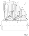
- Fig.1 illustrates a schematic sectional view of a centrifugal compressor 1.
- the sectional view is taken along a plane containing the rotation axis A-A of the compressor rotor.
- the section of Fig. 1 illustrates only a portion of the centrifugal compressor, sufficient for the purposes of the present description.
- the centrifugal compressor 1 of Fig.1 is presented here as an exemplary embodiment of a turbomachine, in which the seal structure of the present disclosure can be advantageously applied.
- the seal structure disclosed herein can be applied also to different kinds of turbomachines, and in different positions of the turbomachine.
- the seal structure can be used whenever sealing around a rotating member, such as a rotor, drum or shaft, between a high pressure area and a low pressure area, is required.
- the centrifugal compressor 1 includes a shaft 3 and one or more impellers 5.
- Fig.1 three impellers 5 are illustrated. While in Fig.1 the impellers 5 are mounted on the shaft 3 for co-rotation therewith in a so-called shrink-fit arrangement, in other embodiments the impellers can be configured as so-called stack-impellers, which are axially stacked and torsionally coupled to one another the aid of a tie-beam and respective Hirth coupling or other coupling features.
- a distancing ring 7 is arranged between each pair of adjacent impellers 5.
- a balance drum 9 s further keyed on shaft 3 for rotation therewith.
- the shaft 3, the impellers 5, the distancing rings 7 and the balance drum 9 form together a rotor 11, which is mounted for rotation around rotation axis A-A according to arrow f11.
- the rotor 11 is housed in a casing (not shown), wherein the stationary components of the compressor 1 are housed.
- the stationary components include diaphragms 13 defining diffusers 15 and return channels 17 of the compressor.
- Each impeller includes an impeller eye 5.1.
- an eye labyrinth seal 21 is positioned around each impeller eye 5.1 to reduce gas leakages from the high-pressure side downstream of the impeller to the low-pressure side upstream the impeller.
- the terms "upstream” and “downstream” are referred to the direction of flow of the process gas through the compressor 1, which is schematically represented by arrows G.
- Each labyrinth seal 21 is mounted in a housing machined in the respective diaphragm of the centrifugal compressor 1.
- Shaft labyrinth seals 23 are further provided between diaphragms 13 and the shaft 3, for instance around the distancing rings 7.
- the shaft labyrinth seals 23 are mounted in respective housings machined in the diaphragms 13.
- a balance drum labyrinth seal 25 is also disposed around the balance drum 9.
- labyrinth seals 21, 23, 25 of the centrifugal compressor 1 can be configured according to the present disclosure.
- Figs. 2 and 3 an embodiment of a generic labyrinth seal is described, to illustrate the novel features thereof.
- Those skilled in sealing technology will be capable of designing labyrinth seals for different uses and different parts within the centrifugal compressor 1, or another turbomachine, embodying the features described below.
- Fig.2 illustrates an exemplary seal structure 30, which can be used in the eye labyrinth seal 21, in the shaft labyrinth seal 23, in the balance drum labyrinth seal 25, or more generally in any different rotor seal within a turbomachine.
- the labyrinth seal 30 includes a carrier ring 33 and a ring-shaped seal element 35.
- the axis or centerline of the seal arrangement is labeled A-A and coincides with the rotation axis of the compressor rotor 11 when the seal structure is mounted in the turbomachine around the compressor rotor 11.
- the carrier ring 33 can be made of a metal or a metal alloy.
- the material used for manufacturing the carrier ring 33 can be selected based on the nature of the process gas, which will get in contact with the seal arrangement 30, on the pressures on the two sides of the seal arrangement, on the dimension of the seal, and on other design considerations.
- the following alloys can be employed: aluminum alloys of the series 2000, one example of which is AVIONAL ® 14; or aluminum alloys of the series 5000, one example of which is PERALUMAN ® , where AVIONAL and PERALUMAN are a trademarks registered to Constellium Valais SA, Switzerland; or aluminum alloys of the series 6000, one example of which is ANTICORODAL ® , where ANTICORODAL is a trademark registered to Novelis Switzerland SA, Switzerland, and martensitic stainless steels.
- carbon steel and low alloy steel can be used.
- austenitic, superaustenitic, duplex and superduplex stainless steels as well Ni-based alloys can be employed.
- the carrier ring should be made of the same material of the diaphragm.
- the seal element 35 can be made mainly of a thermoplastic polymer.
- the seal element 35 can be made of a composite polymeric material having a polymer matrix filled with reinforcing fibers or particles, such as carbon fibers, glass fibers, or the like.
- Polymers like PEK (polyether ketone), PEEK (polyether ether ketone), PAI (polyamide-imides), PEI (polyethylenimine) and PFA (perfluoroalkoxy alkanes) can be used as options.
- Reinforcing fibers can be long or shorts ( ⁇ 30 ⁇ m) depending on the required mechanical characteristics or on the available technology.
- Fig.3 shows an enlarged cross-section of the carrier ring 33 and of the seal element 35.
- the carrier ring 33 includes a circumferential outer wall 33.1, a first side wall 33.2 and a second side wall 33.3.
- the circumferential outer wall 33.1, the first side wall 33.2 and the second side wall 33.3 form an annular groove 33.4 therebetween, which houses the seal element 35.
- the circumferential outer wall 33.1 has a broadly cylindrical shape.
- the inner surface of the circumferential outer wall 33.1 forms the bottom of the annular groove 33.4.
- the outer surface of the circumferential outer wall 33.1 forms a fastening feature 33.5 for coupling to an annular seat formed in a stationary member of the turbomachine, for example the compressor diaphragm, in which the seal structure 30 is mounted.
- the fastening feature includes an annular projection extending from the outer peripheral surface of the circumferential outer wall 33.1.
- the projection has a cross-sectional shape forming an undercut 33.6 for mechanical coupling to the annular seat in the turbomachine.
- Each of the side walls 33.2 and 33.3 includes an inner surface, which can be substantially planar and orthogonal to the centerline or axis A-A of the sealing structure.
- the inner surfaces of the side walls 33.2 and 33.3 extend radially inwardly from the inner surface of the circumferential outer wall 33.1 and form the flanks of the annular groove 33.4.
- Each side wall 33.2 and 33.3 further includes a respective outer surface, which can be substantially parallel to the respective inner surface and can be substantially planar.
- swirl breakers 33.9 can be provided on one or both the external surfaces of the side walls 33.2 and 33.3.
- the seal element 35 includes a main body 35.1 with an external cylindrical surface 35.2 in surface contact with the bottom of the annular groove 33.4.
- the main body 35.1 further includes side surfaces 35.3 and 35.4 in surface contact with the inner surfaces of the first side wall 33.2 and of the second side wall 33.3, respectively.
- the main body 35.1 includes a first region of the seal element, in surface-to-surface contact with the annular groove 33.4 formed in the carrier ring 33.
- the main body 35.1 includes a second, region, namely a sealing region, arranged radially inwardly of the first region and labeled 35.12.
- the second, sealing region 35.12 has a plurality of sealing features adapted to co-act with a rotating part of a rotor.
- the seal structure 30 features a labyrinth seal and the sealing features include annular teeth, blades or lips 35.5, which project radially inwardly from the carrier ring 33 towards the centerline or axis A-A of the seal structure 30.
- a fastening arrangement mechanically couples the carrier ring 33 and the seal element 35 to one another.
- the fastening arrangement includes a first set of fastening pins 37 and a second set of fastening pins 39.
- Each fastening pin 37 of the first set of fastening pins extends in the through hole 33.7 and has an inwardly oriented end projecting in a seat 35.10 formed in the side surface 35.3 of the seal element 35, which is in surface contact with the side wall 33.2.
- Each fastening pin 39 of the second set of fastening pins extends in the through hole 33.8, which extends across the second side wall 33.3 and has an inwardly oriented end housed in a seat 35.11 formed in the side surface 35.4 of the seal element 35, which is in surface contact with the side wall 33.3.
- the seats 35.10 and 35.11 are in the form of blind holes drilled in the seal element 35.
- the holes 33.7 and 33.8 as well as the seats 35.10 and 35.11 are oriented parallel to the axis or centerline A-A of the seal arrangement 30.
- each hole 33.7 and relevant seat 35.10 are collinear with a corresponding hole 33.8 and relevant seat 35.11, such that pairs of fastening pins 37, 39 of the two sets of fastening pins are collinear to one another.
- each seat can have a length which is less than half the thickness of the seal element 35, i.e. less than half the dimension of the seal element 35 in the direction of the centerline, measured between the opposing side surfaces of the seal element 35, where the seats 35.10 and 35.11 are drilled. In Fig.3 such thickness is indicated as "T". In this way the collinear seats remain separate from one another in the form of two opposing blind holes.
- the fastening pins 37, 39 can be locked in the holes 33.7, 33.8 and in the seats 35.10, 35.11 in any suitable way, for instance by gluing, soldering, welding or the like. Gluing may be particularly advantageous, as no heat is applied, which may damage the seal element 35.
- the fastening pins 37, 39 provide a reliable coupling between the carrier ring 33 and the seal element 35.
- the fastening pins 37, 39 provide an effective reaction force opposing a radially inwardly acting pressure, which can be generated by pressurized fluid penetrating the gap between the bottom of the annular groove 33.4 and the external cylindrical surface 35.2 of the seal element 35.
- the above described seal structure 30 can be manufactured in a convenient manner according to the method described below, reference being made to the sequence of Figs. 4A-4G .
- the carrier ring 33 can be manufactured by conventional techniques, e.g. by turning, milling or any other chip removal process, starting from a blank, for instance in form of a tube, until the final net shape thereof is achieved, with the exception of through holes 33.7, 33.8, see Fig.4A .
- the through holes 33.7, 33.8 are manufactured in a subsequent step, as described hereafter.
- the seal element 35 can be manufactured starting from a blank 35B, shown in a cross-sectional view in Fig.4B .
- the blank 35B can have an annular shape, the cross section whereof has a simple square or rectangular shape.
- the blank 35B can be made by conventional technologies as well as 3D-printing manufacturing technologies.
- the blank 35B is then partly machined, e.g. by turning or similar chip-removal procedure, to generate the outer surfaces 35.2, 35.3, 35.4 of the seal element 35, i.e. those surfaces which are intended to be in surface contact with the annular groove 33.4 of the carrier ring 33. See Fig.4C .
- the inwardly facing surface on which the sealing features 35.5 are provided will be machined in a subsequent step, which will be disclosed below.
- the partly machined seal element 35 is then introduced in the annular groove 33.4 of the carrier ring 33, as shown in Fig.4D .
- the fastening pins 37, 39 are introduced and locked, for instance by gluing, see Fig.4F .
- the second, sealing region 35.12 of the seal element 35 can be machined, by turning, for instance, to achieve the final shape, including the teeth 35.5 or other sealing features, see Fig.4G .
- FIG. 5 A modified embodiment (not claimed) of the seal structure 30 is illustrated in Fig.5 .
- the same reference numbers designate the same or equivalent parts shown in Figs 2 and 3 and described above.
- the main difference between the embodiment of Figs.2, 3 and the embodiment of Fig. 5 concerns the fastening arrangement, which mechanically couples the seal element 35 to the carrier ring 33.
- Fig. 5 illustrates a single set of fastening pins 38.
- Each pin 38 extends through both side walls 33.2, 33.3, as well as through a seat 35.13 which extends across the whole thickness (i.e. the dimension in the axial direction) of the seal element 35, from side surface 35.3 to side surface 35.4.
- the fastening pins 38 may be provided with an annular ridge 38.1 abutting against the side of the seal structure 30 facing the high-pressure area, or with any other feature adapted to retain the fastening pins 38 in position against the force resulting from the pressure differential across the seal structure 30.
- the holes 33.7, 33.8 are blind, i.e. restricted to a portion only of the thickness of the relevant side wall, such as not to surface on the side of the carrier ring 33 facing the low-pressure area of the machine where the seal structure 30 is mounted.
- the fastening pins 38 introduced in the blind holes from the high-pressure side will abut against the bottom of the blind holes and will be retained against the force resulting from the pressure differential across the seal structure 30.
- the seal element 35 is formed by a single integral annular member. While this is particularly advantageous in terms of precision of manufacturing and easy assembling, it is not excluded that the seal element 35 be formed by separate annular portions, which are introduced in the annular groove 33.4 of the carrier ring 33. The several annular portions can then be connected to one another by gluing or in any other suitable manner.
- Fig.6 summarizes the main steps of manufacturing methods according to the present disclosure.
Landscapes
- Engineering & Computer Science (AREA)
- General Engineering & Computer Science (AREA)
- Mechanical Engineering (AREA)
- Structures Of Non-Positive Displacement Pumps (AREA)
- Turbine Rotor Nozzle Sealing (AREA)
- Sealing Using Fluids, Sealing Without Contact, And Removal Of Oil (AREA)
Claims (14)
- Structure de joint composite (30) adaptée pour être montée dans une turbomachine, la structure de joint composite comprenant :un anneau porteur (33) ayant : une paroi extérieure circonférentielle (33.1) avec une surface intérieure et une surface extérieure, une première paroi latérale (33.2) et une seconde paroi latérale (33.3), dans laquelle la première paroi latérale et la seconde paroi latérale font saillie radialement vers l'intérieur à partir de la paroi extérieure circonférentielle vers un axe de l'anneau porteur ; dans laquelle une rainure annulaire (33.4) est formée entre la paroi extérieure circonférentielle (33.1), la première paroi latérale (33.2) et la seconde paroi latérale (33.3) ;un élément joint (35) ayant une première zone (35.2) en contact surface à surface avec la rainure annulaire (33.4) et une seconde zone d'étanchéité (35.12) faisant saillie de la rainure annulaire de l'anneau porteur vers l'axe de l'anneau porteur (33) et pourvue d'éléments d'étanchéité (35.5) ; etun agencement de fixation accouplant l'élément joint (35) et l'anneau porteur (33) l'un à l'autre, formant ladite structure de joint composite ; dans laquelle l'agencement de fixation comprend une pluralité de broches de fixation (37, 39) agencées circonférentiellement autour de l'axe de l'anneau porteur (33) ; dans laquelle chaque broche de fixation de la pluralité de broches de fixation s'étend à travers au moins l'une de la première paroi latérale (33.2) et de la seconde paroi latérale (33.3) ; et dans laquelle chaque broche de fixation de la pluralité de broches de fixation (37, 39) vient en prise dans un siège (35.10, 35.11) correspondant formé dans l'élément joint ;caractérisée en ce que la pluralité de broches de fixation comprend : un premier ensemble de broches de fixation (37) s'étendant à travers des trous (33.7) à travers la première paroi latérale (33.2) et venant en prise dans un premier ensemble de sièges (35.10) de l'élément joint (35) ; et un second ensemble de broches de fixation (39) s'étendant à travers des trous (33.8) à travers la seconde paroi latérale (33.3) et venant en prise dans un second ensemble de sièges (35.11) de l'élément joint (35) ; et dans laquelle les sièges (35.10, 35.11) ont la forme de trous borgnes dans l'élément joint (35).
- Structure de joint selon la revendication 1, dans laquelle les broches de fixation (37, 39) sont parallèles à l'axe de l'anneau porteur.
- Structure de joint selon la revendication 1 ou 2, dans laquelle la zone d'étanchéité (35.12) est une zone d'étanchéité de type labyrinthe ; et dans laquelle la zone d'étanchéité comprend une pluralité de dents (35.5) faisant saillie à partir d'une surface intérieure radiale de la zone d'étanchéité vers l'axe de l'anneau porteur.
- Structure de joint selon la revendication 1, 2 ou 3, dans laquelle l'anneau porteur (33) est constitué d'un premier matériau et l'élément joint (35) est constitué d'un second matériau, différent du premier matériau ; dans laquelle l'élément joint (35) est constitué d'un polymère, en particulier d'un polymère thermoplastique, ou d'un matériau polymère composite.
- Structure de joint selon l'une ou plusieurs des revendications précédentes, dans laquelle l'élément joint (35) est formé d'un seul élément en forme d'anneau.
- Structure de joint selon l'une ou plusieurs des revendications précédentes, dans laquelle l'anneau porteur (33) est constitué de l'un parmi un métal et un alliage métallique.
- Structure de joint selon l'une ou plusieurs des revendications précédentes, dans laquelle chaque broche de fixation (37) du premier ensemble est colinéaire avec une broche de fixation (39) respective du second ensemble.
- Structure de joint selon l'une ou plusieurs des revendications précédentes, dans laquelle la surface intérieure forme un fond de la rainure annulaire (33.4), et dans laquelle l'élément joint (35) comporte un corps principal avec une surface cylindrique externe en contact de surface avec le fond de la rainure annulaire (33.4).
- Structure de joint selon l'une ou plusieurs des revendications précédentes, dans laquelle les broches de fixation (37, 39) sont espacées d'une distance angulaire entre environ 18° et environ 36°.
- Structure de joint selon l'une ou plusieurs des revendications précédentes, dans laquelle la paroi extérieure circonférentielle (33.1) de l'anneau porteur (33) comprend un élément de fixation, adaptée pour fixer la structure de joint dans un siège annulaire d'une machine, en particulier d'une turbomachine.
- Structure de joint selon la revendication 10, dans laquelle l'élément de fixation comprend une saillie annulaire s'étendant à partir d'une surface périphérique extérieure de la paroi extérieure circonférentielle ; la saillie annulaire ayant de préférence une forme de section transversale formant une contre-dépouille (33.6), pour l'accouplement mécanique au siège annulaire de la machine.
- Structure de joint selon l'une ou plusieurs des revendications précédentes, dans laquelle au moins l'une de la première paroi latérale et de la seconde paroi latérale (33.2, 33.3) comprend des brise-tourbillons (33.9) formés sur une surface extérieure de celles-ci.
- Machine (1), en particulier turbomachine, comprenant : un boîtier ; un arbre (3) agencé pour tourner dans le boîtier ; au moins une structure de joint selon l'une ou plusieurs des revendications précédentes, adaptée pour fournir une action d'étanchéité sur l'arbre rotatif (3).
- Procédé de fabrication d'une structure de joint, le procédé comprenant les étapes suivantes :insertion d'un élément joint (35) dans une rainure annulaire (33.4) d'un anneau porteur (33), la rainure annulaire (33.4) étant formée entre une paroi extérieure circonférentielle (33.1), une première paroi latérale (33.2) et une seconde paroi latérale (33.3) de l'anneau porteur (33), la première paroi latérale (33.2) et la seconde paroi latérale (33.3) faisant saillie radialement vers l'intérieur à partir de la paroi extérieure circonférentielle (33.1) vers un axe de l'anneau porteur (33) ;accouplement mécanique de l'élément joint (35) à l'anneau porteur (33), de telle sorte que l'élément joint (35) a une première zone (35.2) en contact surface à surface avec la rainure annulaire (33.4) et une seconde zone d'étanchéité (35.12) faisant saillie de la rainure annulaire de l'anneau porteur vers l'axe de l'anneau porteur ;usinage d'une surface faisant face vers l'intérieur de la seconde zone d'étanchéité (35.12) de l'élément joint (35) pour produire des éléments d'étanchéité (35.5) sur celle-ci ;dans lequel l'étape d'accouplement mécanique de l'élément joint (35) à l'anneau porteur (33) comprend l'étape d'introduction d'une pluralité de broches de fixation (37, 39) à travers une pluralité correspondante de trous (33.7, 33.8) s'étendant à travers au moins l'une de la première paroi latérale (33.2) et de la seconde paroi latérale (33.3) et la mise en prise de chacune des broches de fixation (37, 39) dans un siège (35.10, 35.11) correspondant formé dans l'élément joint (35) ;dans lequel l'étape d'introduction de la pluralité de broches de fixation (37, 39) à travers la pluralité correspondante de trous (33.7, 33.8) et de mise en prise de chaque broche de fixation dans le siège correspondant comporte les étapes consistant à :introduire un premier ensemble de broches de fixation (37) à travers un premier ensemble de trous (33.7) s'étendant à travers la première paroi latérale (33.2) et mettre en prise les broches de fixation du premier ensemble dans un premier ensemble de sièges (35.10) formés sur un premier côté de l'élément joint ; etintroduire un second ensemble de broches de fixation (39) à travers un second ensemble de trous (33.8) s'étendant à travers la seconde paroi latérale (33.3) et mettre en prise les broches de fixation du second ensemble dans un second ensemble de sièges (35.11) formés sur un second côté de l'élément joint.
Applications Claiming Priority (2)
| Application Number | Priority Date | Filing Date | Title |
|---|---|---|---|
| IT102019000023850A IT201900023850A1 (it) | 2019-12-12 | 2019-12-12 | Struttura di tenuta composita per una macchina, e metodo per produrre la struttura di tenuta composita |
| PCT/EP2020/025545 WO2021115626A1 (fr) | 2019-12-12 | 2020-11-27 | Structure de joint composite pour une machine, et procédé de fabrication de la structure de joint composite |
Publications (3)
| Publication Number | Publication Date |
|---|---|
| EP4073405A1 EP4073405A1 (fr) | 2022-10-19 |
| EP4073405B1 true EP4073405B1 (fr) | 2025-01-01 |
| EP4073405B8 EP4073405B8 (fr) | 2025-02-19 |
Family
ID=69904099
Family Applications (1)
| Application Number | Title | Priority Date | Filing Date |
|---|---|---|---|
| EP20842193.3A Active EP4073405B8 (fr) | 2019-12-12 | 2020-11-27 | Structure de joint composite pour une machine, et procédé de fabrication de la structure de joint composite |
Country Status (10)
| Country | Link |
|---|---|
| US (1) | US11927099B2 (fr) |
| EP (1) | EP4073405B8 (fr) |
| JP (1) | JP7444988B2 (fr) |
| KR (1) | KR102818307B1 (fr) |
| CN (1) | CN114787544A (fr) |
| AU (1) | AU2020400781B2 (fr) |
| CA (1) | CA3159861A1 (fr) |
| ES (1) | ES3014719T3 (fr) |
| IT (1) | IT201900023850A1 (fr) |
| WO (1) | WO2021115626A1 (fr) |
Families Citing this family (6)
| Publication number | Priority date | Publication date | Assignee | Title |
|---|---|---|---|---|
| KR102517064B1 (ko) * | 2022-10-28 | 2023-04-03 | 터보파워텍(주) | 3d프린팅에 의한 마르텐사이트 스테인리스 스틸을 적층하는 터빈의 래비린스 실링장치 제조방법 |
| IT202300027348A1 (it) * | 2023-12-20 | 2025-06-20 | Nuovo Pignone Tecnologie Srl | Una turbomacchina radiale con una tenuta migliorata sull'occhio della girante |
| PL447689A1 (pl) * | 2024-02-02 | 2025-08-04 | Paprocka Jadwiga Fhu Pamet | Sposób wykonania uszczelnienia wirnika pompy, zwłaszcza peryferalnej i uszczelka wirnika pompy, zwłaszcza peryferalnej |
| US12553356B2 (en) | 2024-06-06 | 2026-02-17 | Pratt & Whitney Canada Corp. | Aircraft engine stationary labyrinth seal for use in a gearbox of an aircraft engine oil system |
| US12503951B2 (en) * | 2024-06-06 | 2025-12-23 | Pratt & Whitney Canada Corp. | Aircraft engine rotary labyrinth seal for use in a gearbox of an aircraft engine oil system |
| US20260085616A1 (en) * | 2024-09-20 | 2026-03-26 | Pratt & Whitney Canada Corp. (P&Wc) | Labyrinth seal and method with separately-formed seal portions |
Family Cites Families (23)
| Publication number | Priority date | Publication date | Assignee | Title |
|---|---|---|---|---|
| DE2243873B2 (de) * | 1972-09-07 | 1975-01-16 | Gutehoffnungshuette Sterkrade Ag, 4200 Oberhausen | Labyrinthdichtung für Turboverdichter |
| US3867060A (en) * | 1973-09-27 | 1975-02-18 | Gen Electric | Shroud assembly |
| JPS52138155U (fr) * | 1976-04-15 | 1977-10-20 | ||
| US5026075A (en) * | 1989-02-16 | 1991-06-25 | Westinghouse Electric Corp. | Radial seal |
| US5403019A (en) * | 1993-05-03 | 1995-04-04 | Dresser-Rand Company | Balanced floating labyrinth seal |
| US5749227A (en) * | 1995-06-07 | 1998-05-12 | Electric Boat Corporation | Steam seal air removal system |
| JPH11197927A (ja) * | 1998-01-13 | 1999-07-27 | Mitsubishi Heavy Ind Ltd | シールフィン先端加工機 |
| JP3977921B2 (ja) * | 1998-05-21 | 2007-09-19 | 三菱重工業株式会社 | ガスタービンのシール分割面接合構造 |
| CA2266831C (fr) * | 1998-04-01 | 2004-07-13 | Mitsubishi Heavy Industries, Ltd. | Structure d'etancheite pour turbine a gaz |
| JP4370033B2 (ja) | 2000-02-01 | 2009-11-25 | 三菱重工業株式会社 | フィン修正加工機 |
| US7494317B2 (en) * | 2005-06-23 | 2009-02-24 | Siemens Energy, Inc. | Ring seal attachment system |
| US20100054924A1 (en) | 2008-09-04 | 2010-03-04 | Mitsubishi Heavy Industries, Ltd. | Brush seal and turbine using the same |
| IT1403222B1 (it) * | 2010-12-30 | 2013-10-17 | Nuovo Pignone Spa | Sistemi e metodi per rastremazione del rompi-vortice |
| ITCO20120019A1 (it) * | 2012-04-27 | 2013-10-28 | Nuovo Pignone Srl | Tenute a labirinto ad alto smorzamento con sagoma elicoidale e mista elicoidale-cilindrica |
| JP6373500B2 (ja) * | 2014-08-08 | 2018-08-15 | シーメンス エナジー インコーポレイテッド | ガスタービンエンジン内のステージ間シールハウジング最適化システム |
| JP6227572B2 (ja) * | 2015-01-27 | 2017-11-08 | 三菱日立パワーシステムズ株式会社 | タービン |
| US10309257B2 (en) * | 2015-03-02 | 2019-06-04 | Rolls-Royce North American Technologies Inc. | Turbine assembly with load pads |
| US10221713B2 (en) * | 2015-05-26 | 2019-03-05 | Rolls-Royce Corporation | Shroud cartridge having a ceramic matrix composite seal segment |
| JP2017075621A (ja) | 2015-10-13 | 2017-04-20 | 株式会社日立製作所 | 環状シール構造及びこれを備えた流体機械 |
| FR3045716B1 (fr) * | 2015-12-18 | 2018-01-26 | Safran Aircraft Engines | Ensemble d'anneau de turbine avec maintien elastique a froid |
| FR3049003B1 (fr) * | 2016-03-21 | 2018-04-06 | Safran Aircraft Engines | Ensemble d'anneau de turbine sans jeu de montage a froid |
| US10208762B2 (en) * | 2016-10-10 | 2019-02-19 | Solar Turbines Incorporated | Swirl brakes for compressors with teeth-on-rotor seals |
| US10927710B2 (en) * | 2018-09-26 | 2021-02-23 | Raytheon Technologies Corporation | Blade outer air seal laminate T-joint |
-
2019
- 2019-12-12 IT IT102019000023850A patent/IT201900023850A1/it unknown
-
2020
- 2020-11-27 AU AU2020400781A patent/AU2020400781B2/en active Active
- 2020-11-27 KR KR1020227023352A patent/KR102818307B1/ko active Active
- 2020-11-27 JP JP2022535084A patent/JP7444988B2/ja active Active
- 2020-11-27 CN CN202080086205.XA patent/CN114787544A/zh active Pending
- 2020-11-27 WO PCT/EP2020/025545 patent/WO2021115626A1/fr not_active Ceased
- 2020-11-27 US US17/756,993 patent/US11927099B2/en active Active
- 2020-11-27 ES ES20842193T patent/ES3014719T3/es active Active
- 2020-11-27 CA CA3159861A patent/CA3159861A1/fr active Pending
- 2020-11-27 EP EP20842193.3A patent/EP4073405B8/fr active Active
Also Published As
| Publication number | Publication date |
|---|---|
| KR102818307B1 (ko) | 2025-06-10 |
| EP4073405A1 (fr) | 2022-10-19 |
| US20230019443A1 (en) | 2023-01-19 |
| CA3159861A1 (fr) | 2021-06-17 |
| WO2021115626A1 (fr) | 2021-06-17 |
| AU2020400781A1 (en) | 2022-07-14 |
| JP7444988B2 (ja) | 2024-03-06 |
| EP4073405B8 (fr) | 2025-02-19 |
| AU2020400781B2 (en) | 2024-01-18 |
| US11927099B2 (en) | 2024-03-12 |
| CN114787544A (zh) | 2022-07-22 |
| ES3014719T3 (en) | 2025-04-24 |
| JP2023506429A (ja) | 2023-02-16 |
| IT201900023850A1 (it) | 2021-06-12 |
| KR20220106841A (ko) | 2022-07-29 |
Similar Documents
| Publication | Publication Date | Title |
|---|---|---|
| US11927099B2 (en) | Composite seal structure for a machine, and method of manufacturing the composite seal structure | |
| JP5674672B2 (ja) | タービンエンジンのロータまたはステータ要素を締結するための環状フランジ | |
| EP2666969B1 (fr) | Structure de diaphragme de turbine | |
| EP1479952B1 (fr) | Dispositif d'étanchéité pour axe | |
| US6343792B1 (en) | Shaft seal and turbine using the same | |
| US6524065B2 (en) | Intermediate-stage seal arrangement | |
| EP3415798B1 (fr) | Joint d'étanchéité sans contact hydrostatique avec poutrelles ressorts d'épaisseur variable | |
| EP3418610B1 (fr) | Joint hydrostatique sans contact comportant une poche de réduction de poids | |
| JP3762661B2 (ja) | タービンロータ | |
| US8636465B2 (en) | Gas turbine engine thermal expansion joint | |
| EP3032149B1 (fr) | Dispositif d'étanchéité, machine rotative et procédé de fabrication d'un dispositif d'étanchéité | |
| EP3409898B1 (fr) | Joints de bande ventrale et procédé | |
| KR20150050472A (ko) | 터빈 노즐 고정 방법 및 시스템 | |
| EP2372085A2 (fr) | Agencement de refroidissement de turbine à vapeur à réaction interne | |
| US20200200019A1 (en) | Turbomachine disc cover mounting arrangement | |
| KR101513062B1 (ko) | 증기터빈 | |
| EA044753B1 (ru) | Композитная уплотнительная структура для машины и способ изготовления композитной уплотнительной структуры | |
| WO2017094159A1 (fr) | Rotor de compresseur centrifuge, compresseur centrifuge, et procédé de fabrication d'un rotor de compresseur centrifuge | |
| US11927101B1 (en) | Machine ring multi-slope tipshoe/tip shroud/outer air shroud | |
| US20040040314A1 (en) | Gas turbine and spacer member for the use therein | |
| AU2024338254A1 (en) | A turbomachine comprising a seal between an outer casing component and an inner casing component, and method | |
| JP2001098902A (ja) | 蒸気冷却ガスタービン | |
| JP2007046540A (ja) | タービンのシール構造 | |
| AU2007234500A1 (en) | Stator shim welding |
Legal Events
| Date | Code | Title | Description |
|---|---|---|---|
| STAA | Information on the status of an ep patent application or granted ep patent |
Free format text: STATUS: UNKNOWN |
|
| STAA | Information on the status of an ep patent application or granted ep patent |
Free format text: STATUS: THE INTERNATIONAL PUBLICATION HAS BEEN MADE |
|
| PUAI | Public reference made under article 153(3) epc to a published international application that has entered the european phase |
Free format text: ORIGINAL CODE: 0009012 |
|
| STAA | Information on the status of an ep patent application or granted ep patent |
Free format text: STATUS: REQUEST FOR EXAMINATION WAS MADE |
|
| 17P | Request for examination filed |
Effective date: 20220701 |
|
| AK | Designated contracting states |
Kind code of ref document: A1 Designated state(s): AL AT BE BG CH CY CZ DE DK EE ES FI FR GB GR HR HU IE IS IT LI LT LU LV MC MK MT NL NO PL PT RO RS SE SI SK SM TR |
|
| DAV | Request for validation of the european patent (deleted) | ||
| DAX | Request for extension of the european patent (deleted) | ||
| P01 | Opt-out of the competence of the unified patent court (upc) registered |
Effective date: 20230526 |
|
| STAA | Information on the status of an ep patent application or granted ep patent |
Free format text: STATUS: EXAMINATION IS IN PROGRESS |
|
| 17Q | First examination report despatched |
Effective date: 20231107 |
|
| REG | Reference to a national code |
Ref legal event code: R079 Ipc: F04D0029160000 Ref country code: DE Ref legal event code: R079 Ref document number: 602020044233 Country of ref document: DE Free format text: PREVIOUS MAIN CLASS: F16J0015440000 Ipc: F04D0029160000 |
|
| GRAP | Despatch of communication of intention to grant a patent |
Free format text: ORIGINAL CODE: EPIDOSNIGR1 |
|
| STAA | Information on the status of an ep patent application or granted ep patent |
Free format text: STATUS: GRANT OF PATENT IS INTENDED |
|
| RIC1 | Information provided on ipc code assigned before grant |
Ipc: F16J 15/447 20060101ALI20241014BHEP Ipc: F01D 25/24 20060101ALI20241014BHEP Ipc: F01D 11/02 20060101ALI20241014BHEP Ipc: F04D 29/16 20060101AFI20241014BHEP |
|
| GRAS | Grant fee paid |
Free format text: ORIGINAL CODE: EPIDOSNIGR3 |
|
| INTG | Intention to grant announced |
Effective date: 20241023 |
|
| GRAA | (expected) grant |
Free format text: ORIGINAL CODE: 0009210 |
|
| STAA | Information on the status of an ep patent application or granted ep patent |
Free format text: STATUS: THE PATENT HAS BEEN GRANTED |
|
| AK | Designated contracting states |
Kind code of ref document: B1 Designated state(s): AL AT BE BG CH CY CZ DE DK EE ES FI FR GB GR HR HU IE IS IT LI LT LU LV MC MK MT NL NO PL PT RO RS SE SI SK SM TR |
|
| RAP3 | Party data changed (applicant data changed or rights of an application transferred) |
Owner name: NUOVO PIGNONE TECHNOLOGIE - S.R.L. |
|
| REG | Reference to a national code |
Ref country code: GB Ref legal event code: FG4D |
|
| REG | Reference to a national code |
Ref country code: DE Ref legal event code: R096 Ref document number: 602020044233 Country of ref document: DE |
|
| REG | Reference to a national code |
Ref country code: CH Ref legal event code: EP |
|
| REG | Reference to a national code |
Ref country code: IE Ref legal event code: FG4D |
|
| REG | Reference to a national code |
Ref country code: CH Ref legal event code: PK Free format text: BERICHTIGUNG B8 |
|
| REG | Reference to a national code |
Ref country code: DE Ref legal event code: R081 Ref document number: 602020044233 Country of ref document: DE Owner name: NUOVO PIGNONE TECNOLOGIE - S.R.L., IT Free format text: FORMER OWNER: NUOVO PIGNONE TECHNOLOGIE S.R.L., FLORENCE, IT |
|
| RAP4 | Party data changed (patent owner data changed or rights of a patent transferred) |
Owner name: NUOVO PIGNONE TECNOLOGIE - S.R.L. |
|
| REG | Reference to a national code |
Ref country code: ES Ref legal event code: FG2A Ref document number: 3014719 Country of ref document: ES Kind code of ref document: T3 Effective date: 20250424 |
|
| REG | Reference to a national code |
Ref country code: LT Ref legal event code: MG9D |
|
| REG | Reference to a national code |
Ref country code: NL Ref legal event code: MP Effective date: 20250101 |
|
| REG | Reference to a national code |
Ref country code: AT Ref legal event code: MK05 Ref document number: 1756511 Country of ref document: AT Kind code of ref document: T Effective date: 20250101 |
|
| PG25 | Lapsed in a contracting state [announced via postgrant information from national office to epo] |
Ref country code: NL Free format text: LAPSE BECAUSE OF FAILURE TO SUBMIT A TRANSLATION OF THE DESCRIPTION OR TO PAY THE FEE WITHIN THE PRESCRIBED TIME-LIMIT Effective date: 20250101 |
|
| PG25 | Lapsed in a contracting state [announced via postgrant information from national office to epo] |
Ref country code: FI Free format text: LAPSE BECAUSE OF FAILURE TO SUBMIT A TRANSLATION OF THE DESCRIPTION OR TO PAY THE FEE WITHIN THE PRESCRIBED TIME-LIMIT Effective date: 20250101 |
|
| PG25 | Lapsed in a contracting state [announced via postgrant information from national office to epo] |
Ref country code: PL Free format text: LAPSE BECAUSE OF FAILURE TO SUBMIT A TRANSLATION OF THE DESCRIPTION OR TO PAY THE FEE WITHIN THE PRESCRIBED TIME-LIMIT Effective date: 20250101 |
|
| PG25 | Lapsed in a contracting state [announced via postgrant information from national office to epo] |
Ref country code: IS Free format text: LAPSE BECAUSE OF FAILURE TO SUBMIT A TRANSLATION OF THE DESCRIPTION OR TO PAY THE FEE WITHIN THE PRESCRIBED TIME-LIMIT Effective date: 20250501 |
|
| PG25 | Lapsed in a contracting state [announced via postgrant information from national office to epo] |
Ref country code: HR Free format text: LAPSE BECAUSE OF FAILURE TO SUBMIT A TRANSLATION OF THE DESCRIPTION OR TO PAY THE FEE WITHIN THE PRESCRIBED TIME-LIMIT Effective date: 20250101 |
|
| PG25 | Lapsed in a contracting state [announced via postgrant information from national office to epo] |
Ref country code: LV Free format text: LAPSE BECAUSE OF FAILURE TO SUBMIT A TRANSLATION OF THE DESCRIPTION OR TO PAY THE FEE WITHIN THE PRESCRIBED TIME-LIMIT Effective date: 20250101 Ref country code: PT Free format text: LAPSE BECAUSE OF FAILURE TO SUBMIT A TRANSLATION OF THE DESCRIPTION OR TO PAY THE FEE WITHIN THE PRESCRIBED TIME-LIMIT Effective date: 20250502 |
|
| PG25 | Lapsed in a contracting state [announced via postgrant information from national office to epo] |
Ref country code: BG Free format text: LAPSE BECAUSE OF FAILURE TO SUBMIT A TRANSLATION OF THE DESCRIPTION OR TO PAY THE FEE WITHIN THE PRESCRIBED TIME-LIMIT Effective date: 20250101 Ref country code: GR Free format text: LAPSE BECAUSE OF FAILURE TO SUBMIT A TRANSLATION OF THE DESCRIPTION OR TO PAY THE FEE WITHIN THE PRESCRIBED TIME-LIMIT Effective date: 20250402 |
|
| PG25 | Lapsed in a contracting state [announced via postgrant information from national office to epo] |
Ref country code: AT Free format text: LAPSE BECAUSE OF FAILURE TO SUBMIT A TRANSLATION OF THE DESCRIPTION OR TO PAY THE FEE WITHIN THE PRESCRIBED TIME-LIMIT Effective date: 20250101 |
|
| PG25 | Lapsed in a contracting state [announced via postgrant information from national office to epo] |
Ref country code: SE Free format text: LAPSE BECAUSE OF FAILURE TO SUBMIT A TRANSLATION OF THE DESCRIPTION OR TO PAY THE FEE WITHIN THE PRESCRIBED TIME-LIMIT Effective date: 20250101 |
|
| REG | Reference to a national code |
Ref country code: DE Ref legal event code: R097 Ref document number: 602020044233 Country of ref document: DE |
|
| PG25 | Lapsed in a contracting state [announced via postgrant information from national office to epo] |
Ref country code: SM Free format text: LAPSE BECAUSE OF FAILURE TO SUBMIT A TRANSLATION OF THE DESCRIPTION OR TO PAY THE FEE WITHIN THE PRESCRIBED TIME-LIMIT Effective date: 20250101 |
|
| PG25 | Lapsed in a contracting state [announced via postgrant information from national office to epo] |
Ref country code: DK Free format text: LAPSE BECAUSE OF FAILURE TO SUBMIT A TRANSLATION OF THE DESCRIPTION OR TO PAY THE FEE WITHIN THE PRESCRIBED TIME-LIMIT Effective date: 20250101 |
|
| PG25 | Lapsed in a contracting state [announced via postgrant information from national office to epo] |
Ref country code: IT Free format text: LAPSE BECAUSE OF FAILURE TO SUBMIT A TRANSLATION OF THE DESCRIPTION OR TO PAY THE FEE WITHIN THE PRESCRIBED TIME-LIMIT Effective date: 20250101 |
|
| PG25 | Lapsed in a contracting state [announced via postgrant information from national office to epo] |
Ref country code: RO Free format text: LAPSE BECAUSE OF FAILURE TO SUBMIT A TRANSLATION OF THE DESCRIPTION OR TO PAY THE FEE WITHIN THE PRESCRIBED TIME-LIMIT Effective date: 20250101 |
|
| PG25 | Lapsed in a contracting state [announced via postgrant information from national office to epo] |
Ref country code: SK Free format text: LAPSE BECAUSE OF FAILURE TO SUBMIT A TRANSLATION OF THE DESCRIPTION OR TO PAY THE FEE WITHIN THE PRESCRIBED TIME-LIMIT Effective date: 20250101 |
|
| PLBE | No opposition filed within time limit |
Free format text: ORIGINAL CODE: 0009261 |
|
| STAA | Information on the status of an ep patent application or granted ep patent |
Free format text: STATUS: NO OPPOSITION FILED WITHIN TIME LIMIT |
|
| REG | Reference to a national code |
Ref country code: CH Ref legal event code: L10 Free format text: ST27 STATUS EVENT CODE: U-0-0-L10-L00 (AS PROVIDED BY THE NATIONAL OFFICE) Effective date: 20251112 |
|
| REG | Reference to a national code |
Ref country code: CH Ref legal event code: U11 Free format text: ST27 STATUS EVENT CODE: U-0-0-U10-U11 (AS PROVIDED BY THE NATIONAL OFFICE) Effective date: 20251201 |
|
| 26N | No opposition filed |
Effective date: 20251002 |
|
| PGFP | Annual fee paid to national office [announced via postgrant information from national office to epo] |
Ref country code: DE Payment date: 20251022 Year of fee payment: 6 |
|
| PGFP | Annual fee paid to national office [announced via postgrant information from national office to epo] |
Ref country code: GB Payment date: 20251022 Year of fee payment: 6 |
|
| PGFP | Annual fee paid to national office [announced via postgrant information from national office to epo] |
Ref country code: NO Payment date: 20251024 Year of fee payment: 6 |
|
| PGFP | Annual fee paid to national office [announced via postgrant information from national office to epo] |
Ref country code: FR Payment date: 20251022 Year of fee payment: 6 |
|
| PGFP | Annual fee paid to national office [announced via postgrant information from national office to epo] |
Ref country code: CH Payment date: 20251201 Year of fee payment: 6 |
|
| PGFP | Annual fee paid to national office [announced via postgrant information from national office to epo] |
Ref country code: CZ Payment date: 20251104 Year of fee payment: 6 |
|
| PGFP | Annual fee paid to national office [announced via postgrant information from national office to epo] |
Ref country code: ES Payment date: 20251201 Year of fee payment: 6 |