EP4074206B1 - Système et procédé pour le confort thermique personnel - Google Patents
Système et procédé pour le confort thermique personnel Download PDFInfo
- Publication number
- EP4074206B1 EP4074206B1 EP21168055.8A EP21168055A EP4074206B1 EP 4074206 B1 EP4074206 B1 EP 4074206B1 EP 21168055 A EP21168055 A EP 21168055A EP 4074206 B1 EP4074206 B1 EP 4074206B1
- Authority
- EP
- European Patent Office
- Prior art keywords
- air
- cooling
- perforated
- channels
- thermoelectric elements
- Prior art date
- Legal status (The legal status is an assumption and is not a legal conclusion. Google has not performed a legal analysis and makes no representation as to the accuracy of the status listed.)
- Active
Links
Images

Classifications
-
- A—HUMAN NECESSITIES
- A41—WEARING APPAREL
- A41D—OUTERWEAR; PROTECTIVE GARMENTS; ACCESSORIES
- A41D13/00—Professional, industrial or sporting protective garments, e.g. surgeons' gowns or garments protecting against blows or punches
- A41D13/002—Professional, industrial or sporting protective garments, e.g. surgeons' gowns or garments protecting against blows or punches with controlled internal environment
- A41D13/0025—Professional, industrial or sporting protective garments, e.g. surgeons' gowns or garments protecting against blows or punches with controlled internal environment by means of forced air circulation
-
- A—HUMAN NECESSITIES
- A41—WEARING APPAREL
- A41D—OUTERWEAR; PROTECTIVE GARMENTS; ACCESSORIES
- A41D13/00—Professional, industrial or sporting protective garments, e.g. surgeons' gowns or garments protecting against blows or punches
- A41D13/002—Professional, industrial or sporting protective garments, e.g. surgeons' gowns or garments protecting against blows or punches with controlled internal environment
- A41D13/005—Professional, industrial or sporting protective garments, e.g. surgeons' gowns or garments protecting against blows or punches with controlled internal environment with controlled temperature
- A41D13/0051—Heated garments
-
- A—HUMAN NECESSITIES
- A41—WEARING APPAREL
- A41D—OUTERWEAR; PROTECTIVE GARMENTS; ACCESSORIES
- A41D13/00—Professional, industrial or sporting protective garments, e.g. surgeons' gowns or garments protecting against blows or punches
- A41D13/002—Professional, industrial or sporting protective garments, e.g. surgeons' gowns or garments protecting against blows or punches with controlled internal environment
- A41D13/005—Professional, industrial or sporting protective garments, e.g. surgeons' gowns or garments protecting against blows or punches with controlled internal environment with controlled temperature
- A41D13/0053—Cooled garments
-
- F—MECHANICAL ENGINEERING; LIGHTING; HEATING; WEAPONS; BLASTING
- F41—WEAPONS
- F41H—ARMOUR; ARMOURED TURRETS; ARMOURED OR ARMED VEHICLES; MEANS OF ATTACK OR DEFENCE, e.g. CAMOUFLAGE, IN GENERAL
- F41H1/00—Personal protection gear
- F41H1/02—Armoured or projectile- or missile-resistant garments; Composite protection fabrics
Definitions
- the invention relates to a system and a method for modification of personal microclimate conditions and in particular to a system and a method for personal thermal comfort for eliminating excess body heat by cooling and drying effects.
- a human body core temperature is typically ⁇ 37 °C and during exercise and exposure to heat an increase of body core temperature more than 3 °C can cause overheating following by possible serious health problems ( Havenith, G. Heat balance when wearing protective clothing. The Annals of Occupational Hygiene 1999, 43, 289-296 ).
- Passive body cooling systems are effective only for a short time and during low physical activity.
- forced flow of cold liquid usually water or a water-glycol mixture
- forced air flow is used ( Vernieuw, C. R., Stephenson, L. A., Kolka, M. A. Thermal comfort and sensation in men wearing a cooling system controlled by skin temperature. Human Factors 2007, 49, 1033-1044 ).
- Principle of air ventilation system is based on permanent air movement in vicinity of human skin by using a tube system or cooling zones formed by separators and elimination of heat excess through clothing openings (collar, armpits, torso).
- Different methods of air ventilation may be applied, as well as different systems which may be stationary or mobile ( Chinevere, T. D., Cadarette, B. S., Goodman, D. A., et al. Efficacy of body ventilation system for reducing strain in warm and hot climates. European Journal of Applied Physiology 2008, 103, 307-314 ).
- U. S. patent application no. 13/905,836 (publication No. US2013/0319031 ) describes a cooling unit that can be used with or without a garment, such as a ballistic vest, that covers a user's torso when worn.
- the cooling unit includes a fan for blowing ambient air; a manifold for distributing to the torso air that is blown by the fan; a hose for connecting the fan to the manifold.
- the manifold may be formed of three overlying panels that are secured together, including an outer panel, a central panel, and an inner panel that is closest to the user's torso when the cooling unit is being worn.
- Main disadvantage of such cooling system is that only ambient air can be used for cooling.
- PCT/US2015/060955 discloses a heating and cooling arrangement comprising at least one integral low voltage heating and cooling source and an efficient flexible heat distribution means for distributing heat and cool across a surface.
- the arrangement may provide air flow through a fan which distributes air through an air splitting chamber.
- a low aspect ratio air moving design includes a thermoelectric module which is in thermal communication with a heat transfer block. As the ambient air transfers through air splitting chamber, it is directed via a conduit through an area for ventilation using ambient air and via a different conduit for interacting with the thermoelectric module for dissipating heat or cold to the surrounding.
- U. S. patent No. US 6,823,678 discloses a wearable air conditioner system, according to the preamble of claim 1, that provides cooling or heating to a flexible material-based device incorporated into standard apparel such as shirts, pants, jackets, dresses, etc.
- the air system includes a ventilation portion located within a flexible material body, a thermoelectric module with heat exchangers on opposite sides, an air stream source, and a power source.
- the ventilation portion has two chambers formed between an inner layer made of a flexible material, an air delivery layer, and an outer layer made of flexible material with plurality of air vents in each of the flexible material inner and outer layers.
- Each of the heat exchangers is in fluid communication with one of the chambers.
- the air stream source provides air flow through the heat exchangers into the chambers and out through plurality of vent holes.
- the wearable air conditioner may optionally include a valve between the module air outflow ducts for selecting either the cooling mode of operation or the heating mode of operation. In the cooling mode the cool air stream is delivered through valve to hose while the hot air stream is passed through exhaust duct. In the heating mode, the hot air stream is delivered through valve to hose while the cool air stream is passed through exhaust duct.
- thermoelectric element An alternative to using valve would involve directly connecting outflow duct to hose and directly exhausting outflow duct to the atmosphere.
- Main disadvantage of such Peltier effect-based system is high battery drain and increased risk of overloading the thermoelectric element.
- Another disadvantage of such a system is that only cooling mode or heating mode of operation is possible at a time using a thermoelectric element and a thermoelectric element is operational in all modes.
- the present invention is dedicated to overcoming of the above shortcomings and for producing further advantages over prior art.
- Object of the present invention is a system and a method for personal thermal comfort for providing extra cooling or heating to a users' body part area for cooling and drying effect.
- the system for personal thermal comfort can be worn as a separate garment or in conjunction with another garment for example a ballistic vest or other protective garment (motorcyclists, industry workers, etc.).
- the system for personal thermal comfort comprises air blowers; a first framework of 3D spacer textile channels for ambient air distribution; a second framework of 3D spacer textile channels for distribution of ambient, extra cooled or heated air flow; thermoelectric elements producing the Peltier effect; heatsinks for dissipating heat and cold from relevant sides of the thermoelectric elements; at least one control valve for control of ambient air distribution in the second framework of 3D spacer textile channels for distribution of ambient, extra cooled or heated air flow; control units for control of the air blowers, a control unit for thermoelectric elements; a battery and optionally a battery charging module; temperature sensors.
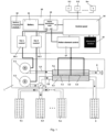
- a system for personal thermal comfort comprises a ventilation device (1) comprising air blowers (1.1, 1.2) for ambient air supply into the system for personal thermal comfort, thermoelectric elements (3.1, 3.2, 3.3), such which produce the Peltier effect, for generating heat or cold on one side and for generating cold or heat on opposite side of each of the thermoelectric elements (3.1, 3.2, 3.3), a first heatsink (4.1) for facilitating heat or cold dissipation from the heat or cold generating side of each of the thermoelectric elements (3.1, 3.2, 3.3), a second heatsink (4.2) for facilitating respectively cold or heat dissipation from the cold or heat generating side of each of the thermoelectric elements (3.1, 3.2, 3.3).
- the system for personal thermal comfort further comprises at least one first framework (5) of perforated 3D spacer textile channels (5.1, 5.2, 5.n) for distribution of ambient air flow for cooling and drying an area of a user's body, at least one second framework of perforated 3D spacer textile channels (6) for distribution of ambient, extra cooled or heated air flow for further cooling, extra cooling or heating an area of a user's body, an ambient air distribution valve (7) for controlling ambient air flow to the at least one first framework (5) of the perforated 3D spacer textile channels (5.1, 5.2, 5.n) and to the at least one second framework of the perforated 3D spacer textile channels (6), an exhaust conduit (8) for channelling the heated air from the ventilation device (1) and out of the system for personal thermal comfort, sensors (9.1, 9.2, 9.n) for measuring temperature of key areas of skin surface.
- the channels (5.1, 5.2, 5.n, 6) comprise an inner layer of 3D spacer textile material which is incorporated into an outer layer of air non-permeable laminate textile material with sealed seams.
- the outer layer of the air non-permeable textile material comprises perforations formed on one side of the channels (5.1, 5.2, 5.n, 6) next to a users' body, hereby creating direct air flow to the body surface.
- the system for personal thermal comfort further comprises an electronic control unit (10) comprising a battery (11) for powering the system for personal thermal comfort, a battery charging module (12) for charging the battery (11), a power distribution node (13) for distributing the power from the battery (11) to electric elements of the system for personal thermal comfort, a control panel (14) with a user interface to control system for personal thermal comfort, a Bluetooth module (15) for wireless data exchange with external devices, control units (16.1, 16.2) for the air blowers (1.1, 1.2).
- an electronic control unit (10) comprising a battery (11) for powering the system for personal thermal comfort, a battery charging module (12) for charging the battery (11), a power distribution node (13) for distributing the power from the battery (11) to electric elements of the system for personal thermal comfort, a control panel (14) with a user interface to control system for personal thermal comfort, a Bluetooth module (15) for wireless data exchange with external devices, control units (16.1, 16.2) for the air blowers (1.1, 1.2).
- the system for personal thermal comfort preferably comprises a first air blower (1.1) in fluid connection with the first heatsink (4.1), being in contact with the heat or cold generating side of each of the thermoelectric elements (3.1, 3.2, 3.3), via a conduit (2.1) for modification of temperature of the first heatsink (4.1) by forcing the hot air to flow out of the system for personal thermal comfort via an exhaust conduit (8).
- Efficiency of the first air blower (1.1) should be at least 38 m 3 /h.
- the system for personal thermal comfort further to the first air blower (1.1) preferably comprises a second air blower (1.2) in fluid connection with the second heatsink (4.2), being in contact with the cold or heat generating side of each of the thermoelectric elements (3.1, 3.2, 3.3), via a conduit (2.2) for relieving cold or heat from the surface of the extra cooling or heat generating side of each of the thermoelectric elements (3.1, 3.2, 3.3) and for forcing the ambient, extra cooled or heated air to flow in the second framework of the 3D spacer textile channels (6) for distribution of ambient, extra cooled or heated air flow.
- a second air blower (1.2) in fluid connection with the second heatsink (4.2), being in contact with the cold or heat generating side of each of the thermoelectric elements (3.1, 3.2, 3.3), via a conduit (2.2) for relieving cold or heat from the surface of the extra cooling or heat generating side of each of the thermoelectric elements (3.1, 3.2, 3.3) and for forcing the ambient, extra cooled or heated air to flow in the
- the second air blower (1.2) is used further for ambient air distribution through the first framework (5) of the perforated 3D spacer textile channels (5.1, 5.2, 5.n).
- the second air blower (1.2) is configured for gaining air pressure of at least 7.5 KPa for supplying air through the first and the second frameworks of the perforated 3D spacer textile channels (5.1, 5.2, 5.n, 6).
- the perforated 3D spacer textile channels (5.1, 5.2, 5.n) of the first framework (5) are disposed in such a way so to essentially cover entire area for even ventilation with cooling and drying effect using ambient air only.
- the perforated 3D spacer textile channels (6) of the second framework are disposed between the centre 3D spacer textile channels (5.1, 5.2) of the first framework (5). Additional ambient air, extra cooled or heated air flow channel (6) is located in parallel to the user's body area where sweat intensity is the highest for example parallel to a user's spine.
- Thermoelectric elements (3.1, 3.2, 3.3) are comprised of plurality of P-type and N-type thermoelectric couples, electrically connected in series between pair of thermally conductive substrates - heatsinks (4.1, 4.2). Application of a current through the thermoelectric elements (3.1, 3.2, 3.3) generates cold on one side and heat on another side.
- the heatsinks (4.1, 4.2) are in thermal contact with the cold generating surface and the heat generating surface and are positioned to receive an air flow there through.
- the heatsinks (4.1, 4.2) are designed hermetic - to achieve maximal transfer efficiency and to avoid air leakage to ensure sufficient air flow to the user.
- the performance efficiency of thermoelectric elements (3.1 , 3.2, 3.n) is maintained by monitoring temperatures of hot and cold sides. Efficiency is strongly dependent on distinction between these two temperatures - the lower is distinction the higher is efficiency.
- the exhaust conduit (8) is as short and as straight as possible to avoid air flow resistance to avoid overheating the thermoelectric elements (3.1, 3.2, 3.3).
- the ambient air distribution valve (7) is proportional valve for supply air distribution between two channels.
- the valve is developed in such manner that overall air conductivity is equal to or greater than outlet of the second air blower (1.2).
- Servomotor is employed for valve (7) control and actual positioning.
- thermocouples should be used, as for example thermo resistors, have sufficient idle current leakage and low accuracy. Thermocouples also are very small in comparison to another sensors, therefore could be positioned directly on a desired measurement point.
- the battery (11) for powering the system for personal thermal comfort is preferably a high energy density, rechargeable battery, or multiple batteries.
- the system for personal thermal comfort can also be powered by an alternative power source such as a 12V vehicle power plug whenever such a source is available.
- Battery management system BMS
- Capacity of the battery should be at least 10Ah.
- Li-Ion battery with integrated current controller Li-Ion battery with integrated current controller.
- the battery charging module (12), for charging the battery (11), is a Li-lon battery charger, with accuracy of charging voltage of ⁇ 0.1 V.
- the power distribution node (13) is used for distributing of power from the battery (11) to electric elements of the system for personal thermal comfort.
- the power distribution node (13) should employ DC-DC step-down converters for control panel and Bluetooth module (15) power supply to minimise conversion losses.
- a current controller with current and voltage feedback should be used for power supply for the thermoelectric elements (3.1, 3.2, 3.3). This is due Volt Ampere dependencies of Peltier effect producing thermoelectric elements (3.1, 3.2, 3.3) - they are temperature dependent, therefore actual power consumption should be monitored for proper operation.
- the control panel (14) with a user interface to control the system for personal thermal comfort is configured to control ventilation of a user's body part with cooling or heating and drying effect.
- a human body has asymmetric dynamics, cooling and heating should be executed with different parameters. Therefore, PI controllers with variable coefficients could be employed. In such applications, coefficients of controller are not locked like in conventional PI controller but are dependent on monitored data and operation mode under certain law.
- the Bluetooth module (15) for wireless data exchange with external devices is implemented for additional control and monitoring using any smart device such as a smartphone.
- the control units (16.1, 16.2) of each of the air blowers (1.1, 1.2) are configured so that: the second air blower (1.2) provides at least 7.5 kPa pressure, blower speed could reach up to 34000 RPM.
- the first air blower (1.1) is a general purpose, voltage-controlled DC fan. PWM technique could be employed for proper control.
- Control unit (17) of the thermoelectric elements (3.1, 3.2, 3.3) operates based on two main feedback parameters:
- the system for personal thermal comfort can operate in ambient cooling mode, in cooling mode with extra cooling and in heating mode.
- thermoelectric elements In ambient cooling mode the thermoelectric elements (3.1, 3.2, 3.3) are not active, the first air blower (1.1) does not operate and the second air blower (1.2) operates in combination with the ambient air distribution valve (7) in such a way that the air is allowed to flow only through the perforated 3D spacer textile channels (5.1, 5.2, 5.n) of the first framework (5), or only through the perforated 3D spacer textile channels (6) of the second framework, or through the perforated 3D spacer textile channels (5.1, 5.2, 5.n, 6) of the first and the second frameworks.
- the ambient air distribution valve (7) allows reducing power consumption of the system because extra air flow is being supplied only to the most demanding for cooling users' body part area in a more concentrated manner wherein the rest body part area intended for cooling is being supplied with ambient temperature air flow producing initial cooling effect, i.e. the cooling and drying effect is essentially enhanced and at least load on the second air blower (1.2) is reduced compared to cooling using only airflow forced through the perforated 3D spacer textile channels (5.1, 5.2, 5.n) of the first framework (5).
- the first air blower (1.1) forces ambient air to flow through the first heatsink (4.1) which draws heat from the thermoelectric elements (3.1, 3.2, 3.3) operating in such a way that electric current passing therethrough forces the thermoelectric elements (3.1, 3.2, 3.3) to generate heat on its surface in contact with the first heatsink (4.1).
- the second heatsink (4.2) is subjected to cooling effect of the opposite side of the thermoelectric elements (3.1, 3.2, 3.3).
- the second air blower (1.2) forces ambient air flow through the air distribution valve (7) which allows to distribute air flow to the perforated 3D spacer textile channels (5.1, 5.2, 5.n, 6) of the first and the second frameworks so that: first portion of ambient air having ambient air temperature is supplied to the perforated 3D spacer textile channels (5.1, 5.2, 5.n) of the first framework (5) for cooling of a part of a user's body using ambient air for cooling; second portion of ambient air is supplied to the second heatsink (4.2) to be cooled due to the cooling effect of the thermoelectric elements (3.1, 3.2, 3.3) having air temperature lower than that of the ambient air and is forced out of the second heatsink (4.2) to the perforated 3D spacer textile channels (6) of the second framework for extra cooling of a part of a users' body using air having temperature lower than that of the body part intended for cooling and lower than that of the ambient air.
- splitting ambient air flow in two separate flows by the ambient air distribution valve (7) allows reducing power consumption of the system for personal thermal comfort because extra cooled air is being supplied only to the most demanding for cooling users' body part area in a more concentrated manner than that of the ambient air wherein the rest body part area intended for cooling is being supplied with ambient temperature air producing initial cooling effect, i.e. load on the thermoelectric elements (3.1, 3.2, 3.3) is thus reduced (compared to cooling only using airflow forced through the thermoelectric elements (3.1, 3.2, 3.3)).
- the cooling effect is essentially enhanced compared with cooling by using only ambient air temperature air flow.
- the first air blower (1.1) does not operate.
- the second heatsink (4.2) is subjected to heating effect of the thermoelectric elements (3.1, 3.2, 3.3).
- the second air blower (1.2) forces ambient air flow through the air distribution valve (7) which allows to distribute air flow to the perforated 3D spacer textile channels (6) of the second framework so that heated air due to the heating effect of the thermoelectric elements (3.1, 3.2, 3.3) having air temperature higher than that of the ambient air is utilised for the body part area heating.
- the perforated 3D spacer textile channels (5.1, 5.2, 5.n, 6) of the first and the second frameworks are attached to the inside mesh structure of the whole garment.
- the perforated 3D spacer soft textile channels (5.1, 5.2, 5.n, 6) of the first and the second frameworks are attached through connecting hoses to the ventilation device (1).
- thermocouples (9) located in the front, chest, and back area, and at the spinal canal.
- skin temperature range is set to 34 - 36 °C.
- extra cooling is activated via the second framework of the perforated 3D spacer soft textile channel (6).
- the air blower (1.2) can generate a pressure of up to 7.5 kPa and supply an air flow of up to 15 m 3 /h.
Landscapes
- Engineering & Computer Science (AREA)
- Environmental & Geological Engineering (AREA)
- Health & Medical Sciences (AREA)
- General Health & Medical Sciences (AREA)
- Physical Education & Sports Medicine (AREA)
- Textile Engineering (AREA)
- General Engineering & Computer Science (AREA)
- Professional, Industrial, Or Sporting Protective Garments (AREA)
Claims (8)
- - Système pour le confort thermique personnel comprenant un dispositif de ventilation (1) comprenant des soufflantes d'air (1.1, 1.2) pour fournir de l'air ambiant dans le système pour le confort thermique personnel, des éléments thermoélectriques (3.1, 3.2, 3.3), tels que produisant l'effet Peltier, pour générer de la chaleur ou du froid sur un côté et pour générer du froid ou de la chaleur sur le côté opposé de chacun des éléments thermoélectriques (3.1, 3.2, 3.3), un premier dissipateur thermique (4.1) pour faciliter la dissipation de la chaleur ou du froid depuis le côté générateur de chaleur ou de froid de chacun des éléments thermoélectriques (3.1, 3.2, 3.3), un second dissipateur thermique (4.2) pour faciliter respectivement la dissipation du froid ou de la chaleur depuis le côté générateur de froid ou de chaleur de chacun des éléments thermoélectriques (3.1, 3.2, 3.3), le système pour le confort thermique personnel comprend en outre des canaux de distribution d'air (5.1, 5.2, 5.n, 6) pour fournir de l'air à une zone sur le corps d'un utilisateur, un conduit d'échappement (8) pour canaliser l'air chauffé du dispositif de ventilation (1), des capteurs (9.1, 9.2, 9.n) pour mesurer la température de zones clés et une unité de commande électronique (10) pour commander le fonctionnement du système caractérisé en ce que le système pour le confort thermique personnel comprend :une première ossature (5) de canaux textiles souples d'espacement 3D perforés (5.1, 5.2, 5.n) pour la distribution d'un flux d'air ambiant pour refroidir et sécher une zone du corps d'un utilisateur ;une seconde ossature de canaux textiles souples d'espacement 3D perforés (6) pour la distribution d'un flux d'air ambiant, extra-refroidi ou chauffé pour un refroidissement supplémentaire, un extra-refroidissement ou un chauffage d'une zone du corps d'un utilisateur ;une vanne de distribution d'air ambiant (7) pour commander le flux d'air ambiant vers la première ossature (5) des canaux textiles souples d'espacement 3D perforés (5.1, 5.2, 5.n) et vers la seconde ossature des canaux textiles souples d'espacement 3D perforés (6) ;une première soufflante d'air (1.1) en liaison fluidique avec le premier dissipateur thermique (4.1), en contact avec le côté générateur de chaleur ou de froid de chacun des éléments thermoélectriques (3.1, 3.2, 3.3), via un conduit (2.1) pour la modification de température du premier dissipateur thermique (4.1) ;une seconde soufflante d'air (1.2) en liaison fluidique avec le second dissipateur thermique (4.2), en contact avec le côté générateur de froid ou de chaleur de chacun des éléments thermoélectriques (3.1, 3.2, 3.3), via un conduit (2.2) pour décharger le froid ou la chaleur provenant de la surface du côté générateur d'extra-refroidissement ou de chaleur de chacun des éléments thermoélectriques (3.1, 3.2, 3.3) et pour forcer l'air ambiant, extra-refroidi ou chauffé à circuler dans la seconde ossature des canaux textiles souples d'espacement 3D perforés (6) pour la distribution du flux d'air ambiant, extra-refroidi ou chauffé.
- - Système selon la revendication 1, où la première ossature (5) des canaux textiles souples d'espacement 3D perforés (5.1, 5.2, 5.n) est disposée de manière à couvrir essentiellement toute la surface pour une ventilation uniforme avec un effet de refroidissement et de séchage en utilisant uniquement l'air ambiant et la seconde ossature des canaux textiles souples d'espacement 3D perforés (6) est disposée entre les canaux textiles souples d'espacement 3D centraux (5.1, 5.2) de la première ossature (5) des canaux textiles souples d'espacement 3D perforés (5.1 , 5.2, 5.n).
- - Système selon l'une quelconque des revendications précédentes où les canaux textiles souples d'espacement 3D (5.1, 5.2, 5.n, 6) des première et seconde ossatures comprennent une couche interne en matériau textile souple perméable à l'air et une couche externe en matériau textile souple non perméable à l'air, où la couche externe du matériau textile non perméable à l'air est formée sur la couche interne du matériau textile perméable à l'air et comprend des perforations formées sur un côté des canaux (5.1, 5.2, 5.n, 6) à côté du corps d'un utilisateur.
- - Système selon l'une quelconque des revendications précédentes où l'efficacité de la première soufflante d'air (1.1) est d'au moins 38 m3/h.
- - Système selon l'une quelconque des revendications précédentes où la seconde soufflante d'air (1.2) est adaptée pour gagner une pression d'air d'au moins 7,5 KPa pour fournir de l'air à travers les première et seconde ossatures des canaux textiles souples d'espacement 3D perforés (5.1, 5.2, 5.n, 6).
- - Système selon l'une quelconque des revendications précédentes où la vanne de distribution d'air ambiant (7) est une vanne proportionnelle pour la distribution d'air fourni entre la première et la seconde ossature des canaux textiles souples d'espacement 3D perforés (5.1, 5.2, 5.n, 6) dans lequel la conductivité globale de l'air est égale ou supérieure à la sortie de la seconde soufflante d'air (1.2).
- - Système selon l'une quelconque des revendications précédentes dans lequel l'unité de commande électronique (10) comprend :une batterie (11) pour alimenter électriquement le système pour le confort thermique personnel ;un module de charge de batterie (12) pour charger la batterie (11) ;un noeud de distribution d'énergie (13) pour distribuer l'énergie de la batterie (11) aux éléments électriques du système pour le confort thermique personnel ;un panneau de commande (14) avec une interface utilisateur pour commander le système pour le confort thermique personnel ;un module Bluetooth (15) pour l'échange de données sans fil avec des dispositifs externes ;des unités de commande (16.1, 16.2) pour les soufflantes d'air (1.1, 1.2).
- - Procédé de modification du microclimat personnel au moyen d'un système pour le confort thermique personnel comprenant des soufflantes d'air (1.1, 1.2) pour fournir de l'air ambiant dans le système pour le confort thermique personnel, des éléments thermoélectriques (3.1, 3.2, 3.3), tels que produisant l'effet Peltier, pour générer de la chaleur ou du froid sur un côté et pour générer du froid ou de la chaleur sur le côté opposé de chacun des éléments thermoélectriques (3.1, 3.2, 3.3), un premier dissipateur thermique (4.1) pour faciliter la dissipation de chaleur ou du froid depuis le côté générateur de chaleur ou de froid de chacun des éléments thermoélectriques (3.1, 3.2, 3.3), un second dissipateur thermique (4.2) pour faciliter respectivement la dissipation du froid ou de la chaleur depuis le côté générateur de froid ou de chaleur de chacun des éléments thermoélectriques (3.1, 3.2, 3.3), des canaux de distribution d'air (5.1, 5.2, 5.n, 6) pour fournir de l'air à une zone du corps d'un utilisateur, un conduit d'échappement (8) pour canaliser l'air chauffé du dispositif de ventilation (1), des capteurs (9.1, 9.2, 9.n) pour mesurer la température des zones clés et une unité de commande électronique (10) pour commander le fonctionnement du système pour le confort thermique personnel caractérisé en ce que le système pour le confort thermique personnel fonctionne sélectivement en mode de refroidissement ambiant ou en mode de refroidissement avec un mode d'extra-refroidissement ou de chauffage dans lequel :en mode refroidissement avec fonctionnement d'extra-refroidissement du système pour le confort thermique personnel, une première soufflante d'air (1.1) force l'air ambiant à circuler à travers le premier dissipateur thermique (4.1) puisant la chaleur de chacun des éléments thermoélectriques (3.1, 3.2, 3.3), un second dissipateur thermique (4.2) est soumis à un effet de refroidissement des côtés opposés de chacun des éléments thermoélectriques (3.1, 3.2, 3.3), et une seconde soufflante d'air (1.2) force le flux d'air ambiant à travers une vanne de distribution d'air (7) distribuant de manière commandée le flux d'air vers une première et vers une seconde ossature de canaux textiles souples d'espacement 3D perforés (5.1, 5.2, 5.n, 6) de sorte qu'une première partie d'air ambiant ayant la température de l'air ambiant est fournie à la première ossature (5) des canaux textiles souples d'espacement 3D perforés (5.1, 5.2, 5.n) pour le refroidissement d'une partie du corps d'un utilisateur en utilisant l'air ambiant pour le refroidissement, la seconde partie de l'air ambiant est fournie au second dissipateur thermique (4.2) pour être refroidie en raison de l'effet de refroidissement des éléments thermoélectriques (3.1, 3.2, 3.3) ayant une température d'air inférieure à celle de l'air ambiant et est expulsé du second dissipateur thermique (4.2) vers la seconde ossature des canaux textiles souples d'espacement 3D perforés (6) pour l'extra-refroidissement d'une partie du corps d'un utilisateur en utilisant de l'air ayant une température inférieure à celle de la partie du corps destinée au refroidissement et inférieure à celle de l'air ambiant ;en mode refroidissement ambiant chacun des éléments thermoélectriques (3.1, 3.2, 3.3) est inactif, la première soufflante d'air (1.1) ne fonctionne pas et la seconde soufflante d'air (1.2) fonctionne en combinaison avec la vanne de distribution d'air ambiant (7) de manière à ce que l'air ne puisse circuler qu'à travers la première ossature (5) des canaux textiles souples d'espacement 3D perforés (5.1, 5.2, 5.n) ou uniquement à travers la seconde ossature des canaux textiles souples d'espacement 3D perforés(6) ou à travers les première et seconde ossatures des canaux textiles souples d'espacement 3D perforés (5.1, 5.2, 5.n, 6) ;dans le fonctionnement en mode chauffage du système pour le confort thermique personnel, la première soufflante d'air (1.1) ne fonctionne pas, le second dissipateur thermique (4.2) est soumis à l'effet de chauffage de chacun des éléments thermoélectriques (3.1, 3.2, 3.3), la seconde soufflante d'air (1.2) force le flux d'air ambiant à travers la vanne de distribution d'air (7) en dirigeant le flux d'air vers la seconde ossature des canaux textiles souples d'espacement 3D perforés (6) de sorte que l'air chauffé en raison de l'effet de chauffage des éléments thermoélectriques (3.1, 3.2, 3.3) ayant une température de l'air supérieure à celle de l'air ambiant est utilisé pour le chauffage de la zone des parties du corps.
Priority Applications (1)
| Application Number | Priority Date | Filing Date | Title |
|---|---|---|---|
| EP21168055.8A EP4074206B1 (fr) | 2021-04-13 | 2021-04-13 | Système et procédé pour le confort thermique personnel |
Applications Claiming Priority (1)
| Application Number | Priority Date | Filing Date | Title |
|---|---|---|---|
| EP21168055.8A EP4074206B1 (fr) | 2021-04-13 | 2021-04-13 | Système et procédé pour le confort thermique personnel |
Publications (3)
| Publication Number | Publication Date |
|---|---|
| EP4074206A1 EP4074206A1 (fr) | 2022-10-19 |
| EP4074206B1 true EP4074206B1 (fr) | 2023-08-09 |
| EP4074206C0 EP4074206C0 (fr) | 2023-08-09 |
Family
ID=75497855
Family Applications (1)
| Application Number | Title | Priority Date | Filing Date |
|---|---|---|---|
| EP21168055.8A Active EP4074206B1 (fr) | 2021-04-13 | 2021-04-13 | Système et procédé pour le confort thermique personnel |
Country Status (1)
| Country | Link |
|---|---|
| EP (1) | EP4074206B1 (fr) |
Family Cites Families (4)
| Publication number | Priority date | Publication date | Assignee | Title |
|---|---|---|---|---|
| US6823678B1 (en) | 2003-12-22 | 2004-11-30 | Ferrotec (Usa) Corporation | Air conditioner system for flexible material-based devices |
| KR101341334B1 (ko) * | 2012-03-26 | 2013-12-13 | 주식회사 제펠 | 미세기후 조절기 |
| WO2013181398A2 (fr) | 2012-05-31 | 2013-12-05 | Safariland, Llc | Module refroidissant |
| US20180142924A1 (en) * | 2015-05-08 | 2018-05-24 | Eddy Limon | Protective vest apparatus and system |
-
2021
- 2021-04-13 EP EP21168055.8A patent/EP4074206B1/fr active Active
Also Published As
| Publication number | Publication date |
|---|---|
| EP4074206A1 (fr) | 2022-10-19 |
| EP4074206C0 (fr) | 2023-08-09 |
Similar Documents
| Publication | Publication Date | Title |
|---|---|---|
| US6823678B1 (en) | Air conditioner system for flexible material-based devices | |
| KR100519343B1 (ko) | 기능성 의복 | |
| US20180317572A1 (en) | Personal air-conditioning system | |
| KR101540477B1 (ko) | 온도조절 기능을 갖는 스마트 의복 | |
| US7186957B2 (en) | Temperature regulated clothing | |
| EP3350537B1 (fr) | Gilet protecteur avec mécanismes actifs et passifs de refroidissement | |
| CA2382928A1 (fr) | Vetement pour la thermoregulation | |
| EP3225120B1 (fr) | Vêtement respirant | |
| JP6080237B1 (ja) | 衣服用冷暖房ユニット | |
| JP2025066030A (ja) | ウェアラブル温度調節装置 | |
| CN107411317A (zh) | 冷暖双供式太阳能背包 | |
| JP3244984U (ja) | 送風機能付き衣服 | |
| US20240032621A1 (en) | Air Conditioning Cooling and Warming Clothing and Footwear for Humans and Domestic Mammals controlled by computer generated programmable .Thermostat | |
| EP4074206B1 (fr) | Système et procédé pour le confort thermique personnel | |
| WO2019229773A1 (fr) | Vêtement de confort global intelligent tous temps, système et procédé associés | |
| US20030098143A1 (en) | Fluid heat exchanger assembly and personal cooling device | |
| CN217565017U (zh) | 一种可调整冷热部位的空调服 | |
| WO2018034766A1 (fr) | Climatiseur personnel portable | |
| CN108784919A (zh) | 穿戴式体表温度恒定调节装置 | |
| CN209801857U (zh) | 可穿戴便捷式空气调节设备及系统 | |
| Vasilev et al. | Methods for personal cooling in hot environment used in clothing and wearables | |
| CN212378163U (zh) | 用于人体调节的温度调节器、温度调节服及抽气降温服 | |
| JP2006136628A (ja) | 携帯用冷風・温風装置 | |
| CN212754341U (zh) | 人体用模块化温度调节器、温度调节服及温度调节背包 | |
| CN210185818U (zh) | 一种穿戴式体表温度恒定调节装置 |
Legal Events
| Date | Code | Title | Description |
|---|---|---|---|
| PUAI | Public reference made under article 153(3) epc to a published international application that has entered the european phase |
Free format text: ORIGINAL CODE: 0009012 |
|
| STAA | Information on the status of an ep patent application or granted ep patent |
Free format text: STATUS: THE APPLICATION HAS BEEN PUBLISHED |
|
| AK | Designated contracting states |
Kind code of ref document: A1 Designated state(s): AL AT BE BG CH CY CZ DE DK EE ES FI FR GB GR HR HU IE IS IT LI LT LU LV MC MK MT NL NO PL PT RO RS SE SI SK SM TR |
|
| STAA | Information on the status of an ep patent application or granted ep patent |
Free format text: STATUS: REQUEST FOR EXAMINATION WAS MADE |
|
| 17P | Request for examination filed |
Effective date: 20221101 |
|
| GRAP | Despatch of communication of intention to grant a patent |
Free format text: ORIGINAL CODE: EPIDOSNIGR1 |
|
| STAA | Information on the status of an ep patent application or granted ep patent |
Free format text: STATUS: GRANT OF PATENT IS INTENDED |
|
| GRAS | Grant fee paid |
Free format text: ORIGINAL CODE: EPIDOSNIGR3 |
|
| INTG | Intention to grant announced |
Effective date: 20230313 |
|
| RIN1 | Information on inventor provided before grant (corrected) |
Inventor name: BUCAS, REMIGIJUS Inventor name: BASKYS, ALGIRDAS Inventor name: BLEIZGYS, VYTAUTAS Inventor name: DERVINIS, ALDAS Inventor name: SAPUROV, MARTYNAS Inventor name: KUBILIENE , DIANA Inventor name: ABRAITIENE , AUSRA |
|
| GRAA | (expected) grant |
Free format text: ORIGINAL CODE: 0009210 |
|
| STAA | Information on the status of an ep patent application or granted ep patent |
Free format text: STATUS: THE PATENT HAS BEEN GRANTED |
|
| AK | Designated contracting states |
Kind code of ref document: B1 Designated state(s): AL AT BE BG CH CY CZ DE DK EE ES FI FR GB GR HR HU IE IS IT LI LT LU LV MC MK MT NL NO PL PT RO RS SE SI SK SM TR |
|
| REG | Reference to a national code |
Ref country code: GB Ref legal event code: FG4D |
|
| REG | Reference to a national code |
Ref country code: CH Ref legal event code: EP |
|
| REG | Reference to a national code |
Ref country code: DE Ref legal event code: R096 Ref document number: 602021004079 Country of ref document: DE |
|
| REG | Reference to a national code |
Ref country code: IE Ref legal event code: FG4D |
|
| U01 | Request for unitary effect filed |
Effective date: 20230908 |
|
| U07 | Unitary effect registered |
Designated state(s): AT BE BG DE DK EE FI FR IT LT LU LV MT NL PT SE SI Effective date: 20230919 |
|
| PG25 | Lapsed in a contracting state [announced via postgrant information from national office to epo] |
Ref country code: GR Free format text: LAPSE BECAUSE OF FAILURE TO SUBMIT A TRANSLATION OF THE DESCRIPTION OR TO PAY THE FEE WITHIN THE PRESCRIBED TIME-LIMIT Effective date: 20231110 |
|
| PG25 | Lapsed in a contracting state [announced via postgrant information from national office to epo] |
Ref country code: IS Free format text: LAPSE BECAUSE OF FAILURE TO SUBMIT A TRANSLATION OF THE DESCRIPTION OR TO PAY THE FEE WITHIN THE PRESCRIBED TIME-LIMIT Effective date: 20231209 |
|
| PG25 | Lapsed in a contracting state [announced via postgrant information from national office to epo] |
Ref country code: RS Free format text: LAPSE BECAUSE OF FAILURE TO SUBMIT A TRANSLATION OF THE DESCRIPTION OR TO PAY THE FEE WITHIN THE PRESCRIBED TIME-LIMIT Effective date: 20230809 Ref country code: NO Free format text: LAPSE BECAUSE OF FAILURE TO SUBMIT A TRANSLATION OF THE DESCRIPTION OR TO PAY THE FEE WITHIN THE PRESCRIBED TIME-LIMIT Effective date: 20231109 Ref country code: IS Free format text: LAPSE BECAUSE OF FAILURE TO SUBMIT A TRANSLATION OF THE DESCRIPTION OR TO PAY THE FEE WITHIN THE PRESCRIBED TIME-LIMIT Effective date: 20231209 Ref country code: HR Free format text: LAPSE BECAUSE OF FAILURE TO SUBMIT A TRANSLATION OF THE DESCRIPTION OR TO PAY THE FEE WITHIN THE PRESCRIBED TIME-LIMIT Effective date: 20230809 Ref country code: GR Free format text: LAPSE BECAUSE OF FAILURE TO SUBMIT A TRANSLATION OF THE DESCRIPTION OR TO PAY THE FEE WITHIN THE PRESCRIBED TIME-LIMIT Effective date: 20231110 |
|
| PG25 | Lapsed in a contracting state [announced via postgrant information from national office to epo] |
Ref country code: PL Free format text: LAPSE BECAUSE OF FAILURE TO SUBMIT A TRANSLATION OF THE DESCRIPTION OR TO PAY THE FEE WITHIN THE PRESCRIBED TIME-LIMIT Effective date: 20230809 |
|
| PG25 | Lapsed in a contracting state [announced via postgrant information from national office to epo] |
Ref country code: ES Free format text: LAPSE BECAUSE OF FAILURE TO SUBMIT A TRANSLATION OF THE DESCRIPTION OR TO PAY THE FEE WITHIN THE PRESCRIBED TIME-LIMIT Effective date: 20230809 |
|
| PG25 | Lapsed in a contracting state [announced via postgrant information from national office to epo] |
Ref country code: SM Free format text: LAPSE BECAUSE OF FAILURE TO SUBMIT A TRANSLATION OF THE DESCRIPTION OR TO PAY THE FEE WITHIN THE PRESCRIBED TIME-LIMIT Effective date: 20230809 Ref country code: RO Free format text: LAPSE BECAUSE OF FAILURE TO SUBMIT A TRANSLATION OF THE DESCRIPTION OR TO PAY THE FEE WITHIN THE PRESCRIBED TIME-LIMIT Effective date: 20230809 Ref country code: ES Free format text: LAPSE BECAUSE OF FAILURE TO SUBMIT A TRANSLATION OF THE DESCRIPTION OR TO PAY THE FEE WITHIN THE PRESCRIBED TIME-LIMIT Effective date: 20230809 Ref country code: CZ Free format text: LAPSE BECAUSE OF FAILURE TO SUBMIT A TRANSLATION OF THE DESCRIPTION OR TO PAY THE FEE WITHIN THE PRESCRIBED TIME-LIMIT Effective date: 20230809 Ref country code: SK Free format text: LAPSE BECAUSE OF FAILURE TO SUBMIT A TRANSLATION OF THE DESCRIPTION OR TO PAY THE FEE WITHIN THE PRESCRIBED TIME-LIMIT Effective date: 20230809 |
|
| REG | Reference to a national code |
Ref country code: DE Ref legal event code: R097 Ref document number: 602021004079 Country of ref document: DE |
|
| U20 | Renewal fee for the european patent with unitary effect paid |
Year of fee payment: 4 Effective date: 20240429 |
|
| PLBE | No opposition filed within time limit |
Free format text: ORIGINAL CODE: 0009261 |
|
| STAA | Information on the status of an ep patent application or granted ep patent |
Free format text: STATUS: NO OPPOSITION FILED WITHIN TIME LIMIT |
|
| 26N | No opposition filed |
Effective date: 20240513 |
|
| PG25 | Lapsed in a contracting state [announced via postgrant information from national office to epo] |
Ref country code: MC Free format text: LAPSE BECAUSE OF FAILURE TO SUBMIT A TRANSLATION OF THE DESCRIPTION OR TO PAY THE FEE WITHIN THE PRESCRIBED TIME-LIMIT Effective date: 20230809 |
|
| PG25 | Lapsed in a contracting state [announced via postgrant information from national office to epo] |
Ref country code: MC Free format text: LAPSE BECAUSE OF FAILURE TO SUBMIT A TRANSLATION OF THE DESCRIPTION OR TO PAY THE FEE WITHIN THE PRESCRIBED TIME-LIMIT Effective date: 20230809 |
|
| REG | Reference to a national code |
Ref country code: CH Ref legal event code: PL |
|
| PG25 | Lapsed in a contracting state [announced via postgrant information from national office to epo] |
Ref country code: CH Free format text: LAPSE BECAUSE OF NON-PAYMENT OF DUE FEES Effective date: 20240430 |
|
| PG25 | Lapsed in a contracting state [announced via postgrant information from national office to epo] |
Ref country code: IE Free format text: LAPSE BECAUSE OF NON-PAYMENT OF DUE FEES Effective date: 20240413 |
|
| U20 | Renewal fee for the european patent with unitary effect paid |
Year of fee payment: 5 Effective date: 20250423 |
|
| PGFP | Annual fee paid to national office [announced via postgrant information from national office to epo] |
Ref country code: GB Payment date: 20250423 Year of fee payment: 5 |
|
| PG25 | Lapsed in a contracting state [announced via postgrant information from national office to epo] |
Ref country code: CY Free format text: LAPSE BECAUSE OF FAILURE TO SUBMIT A TRANSLATION OF THE DESCRIPTION OR TO PAY THE FEE WITHIN THE PRESCRIBED TIME-LIMIT; INVALID AB INITIO Effective date: 20210413 |
|
| PG25 | Lapsed in a contracting state [announced via postgrant information from national office to epo] |
Ref country code: HU Free format text: LAPSE BECAUSE OF FAILURE TO SUBMIT A TRANSLATION OF THE DESCRIPTION OR TO PAY THE FEE WITHIN THE PRESCRIBED TIME-LIMIT; INVALID AB INITIO Effective date: 20210413 |