EP4074384A1 - Système de batterie et procédé d'extinction d'incendie pour système de batterie - Google Patents
Système de batterie et procédé d'extinction d'incendie pour système de batterie Download PDFInfo
- Publication number
- EP4074384A1 EP4074384A1 EP20913294.3A EP20913294A EP4074384A1 EP 4074384 A1 EP4074384 A1 EP 4074384A1 EP 20913294 A EP20913294 A EP 20913294A EP 4074384 A1 EP4074384 A1 EP 4074384A1
- Authority
- EP
- European Patent Office
- Prior art keywords
- battery
- battery module
- fire extinguishing
- management system
- system bms
- Prior art date
- Legal status (The legal status is an assumption and is not a legal conclusion. Google has not performed a legal analysis and makes no representation as to the accuracy of the status listed.)
- Withdrawn
Links
- 238000000034 method Methods 0.000 title claims abstract description 83
- 238000001514 detection method Methods 0.000 claims abstract description 87
- 239000000779 smoke Substances 0.000 claims description 56
- 239000003795 chemical substances by application Substances 0.000 claims description 54
- 238000004891 communication Methods 0.000 claims description 40
- 239000007921 spray Substances 0.000 claims description 32
- 230000008569 process Effects 0.000 claims description 31
- 238000007599 discharging Methods 0.000 claims description 15
- 238000005507 spraying Methods 0.000 claims description 6
- 238000007726 management method Methods 0.000 description 108
- 239000007789 gas Substances 0.000 description 53
- 239000000178 monomer Substances 0.000 description 33
- 238000010586 diagram Methods 0.000 description 16
- 239000002360 explosive Substances 0.000 description 13
- 238000003860 storage Methods 0.000 description 13
- 238000012545 processing Methods 0.000 description 11
- 238000004146 energy storage Methods 0.000 description 10
- 230000006870 function Effects 0.000 description 9
- 238000004590 computer program Methods 0.000 description 8
- 230000007480 spreading Effects 0.000 description 8
- 238000003892 spreading Methods 0.000 description 8
- 239000000126 substance Substances 0.000 description 7
- 238000005516 engineering process Methods 0.000 description 6
- VNWKTOKETHGBQD-UHFFFAOYSA-N methane Chemical compound C VNWKTOKETHGBQD-UHFFFAOYSA-N 0.000 description 6
- WVSNNWIIMPNRDB-UHFFFAOYSA-N 1,1,1,3,3,4,4,5,5,6,6,6-dodecafluorohexan-2-one Chemical compound FC(F)(F)C(=O)C(F)(F)C(F)(F)C(F)(F)C(F)(F)F WVSNNWIIMPNRDB-UHFFFAOYSA-N 0.000 description 5
- 230000001960 triggered effect Effects 0.000 description 5
- CURLTUGMZLYLDI-UHFFFAOYSA-N Carbon dioxide Chemical compound O=C=O CURLTUGMZLYLDI-UHFFFAOYSA-N 0.000 description 4
- 239000000443 aerosol Substances 0.000 description 4
- 238000006243 chemical reaction Methods 0.000 description 4
- 230000007246 mechanism Effects 0.000 description 4
- UGFAIRIUMAVXCW-UHFFFAOYSA-N Carbon monoxide Chemical compound [O+]#[C-] UGFAIRIUMAVXCW-UHFFFAOYSA-N 0.000 description 3
- OTMSDBZUPAUEDD-UHFFFAOYSA-N Ethane Chemical compound CC OTMSDBZUPAUEDD-UHFFFAOYSA-N 0.000 description 3
- VGGSQFUCUMXWEO-UHFFFAOYSA-N Ethene Chemical compound C=C VGGSQFUCUMXWEO-UHFFFAOYSA-N 0.000 description 3
- 239000005977 Ethylene Substances 0.000 description 3
- HSFWRNGVRCDJHI-UHFFFAOYSA-N alpha-acetylene Natural products C#C HSFWRNGVRCDJHI-UHFFFAOYSA-N 0.000 description 3
- 229910002091 carbon monoxide Inorganic materials 0.000 description 3
- 230000008878 coupling Effects 0.000 description 3
- 238000010168 coupling process Methods 0.000 description 3
- 238000005859 coupling reaction Methods 0.000 description 3
- 125000002534 ethynyl group Chemical group [H]C#C* 0.000 description 3
- 239000001257 hydrogen Substances 0.000 description 3
- 229910052739 hydrogen Inorganic materials 0.000 description 3
- 125000004435 hydrogen atom Chemical class [H]* 0.000 description 3
- HBBGRARXTFLTSG-UHFFFAOYSA-N Lithium ion Chemical compound [Li+] HBBGRARXTFLTSG-UHFFFAOYSA-N 0.000 description 2
- 238000009825 accumulation Methods 0.000 description 2
- 239000001569 carbon dioxide Substances 0.000 description 2
- 229910002092 carbon dioxide Inorganic materials 0.000 description 2
- 238000002485 combustion reaction Methods 0.000 description 2
- 238000001816 cooling Methods 0.000 description 2
- 238000013500 data storage Methods 0.000 description 2
- 238000011161 development Methods 0.000 description 2
- 230000000694 effects Effects 0.000 description 2
- 230000005764 inhibitory process Effects 0.000 description 2
- 229910001416 lithium ion Inorganic materials 0.000 description 2
- 229910021645 metal ion Inorganic materials 0.000 description 2
- 239000003595 mist Substances 0.000 description 2
- 238000012544 monitoring process Methods 0.000 description 2
- 150000003254 radicals Chemical class 0.000 description 2
- 238000012549 training Methods 0.000 description 2
- 206010003497 Asphyxia Diseases 0.000 description 1
- IJGRMHOSHXDMSA-UHFFFAOYSA-N Atomic nitrogen Chemical compound N#N IJGRMHOSHXDMSA-UHFFFAOYSA-N 0.000 description 1
- WHXSMMKQMYFTQS-UHFFFAOYSA-N Lithium Chemical compound [Li] WHXSMMKQMYFTQS-UHFFFAOYSA-N 0.000 description 1
- 238000010521 absorption reaction Methods 0.000 description 1
- 230000009471 action Effects 0.000 description 1
- 238000013528 artificial neural network Methods 0.000 description 1
- 150000001768 cations Chemical class 0.000 description 1
- 238000013461 design Methods 0.000 description 1
- 238000004880 explosion Methods 0.000 description 1
- UKACHOXRXFQJFN-UHFFFAOYSA-N heptafluoropropane Chemical compound FC(F)C(F)(F)C(F)(F)F UKACHOXRXFQJFN-UHFFFAOYSA-N 0.000 description 1
- 238000009434 installation Methods 0.000 description 1
- 238000002955 isolation Methods 0.000 description 1
- 239000007788 liquid Substances 0.000 description 1
- 229910052744 lithium Inorganic materials 0.000 description 1
- 238000004519 manufacturing process Methods 0.000 description 1
- JCXJVPUVTGWSNB-UHFFFAOYSA-N nitrogen dioxide Inorganic materials O=[N]=O JCXJVPUVTGWSNB-UHFFFAOYSA-N 0.000 description 1
- 230000003287 optical effect Effects 0.000 description 1
- 230000002035 prolonged effect Effects 0.000 description 1
- 238000011160 research Methods 0.000 description 1
- 239000007787 solid Substances 0.000 description 1
- 230000003068 static effect Effects 0.000 description 1
- 238000012546 transfer Methods 0.000 description 1
- XLYOFNOQVPJJNP-UHFFFAOYSA-N water Substances O XLYOFNOQVPJJNP-UHFFFAOYSA-N 0.000 description 1
Images




Classifications
-
- H—ELECTRICITY
- H01—ELECTRIC ELEMENTS
- H01M—PROCESSES OR MEANS, e.g. BATTERIES, FOR THE DIRECT CONVERSION OF CHEMICAL ENERGY INTO ELECTRICAL ENERGY
- H01M10/00—Secondary cells; Manufacture thereof
- H01M10/42—Methods or arrangements for servicing or maintenance of secondary cells or secondary half-cells
- H01M10/48—Accumulators combined with arrangements for measuring, testing or indicating the condition of cells, e.g. the level or density of the electrolyte
- H01M10/486—Accumulators combined with arrangements for measuring, testing or indicating the condition of cells, e.g. the level or density of the electrolyte for measuring temperature
-
- A—HUMAN NECESSITIES
- A62—LIFE-SAVING; FIRE-FIGHTING
- A62C—FIRE-FIGHTING
- A62C37/00—Control of fire-fighting equipment
- A62C37/36—Control of fire-fighting equipment an actuating signal being generated by a sensor separate from an outlet device
- A62C37/44—Control of fire-fighting equipment an actuating signal being generated by a sensor separate from an outlet device only the sensor being in the danger zone
-
- H—ELECTRICITY
- H01—ELECTRIC ELEMENTS
- H01M—PROCESSES OR MEANS, e.g. BATTERIES, FOR THE DIRECT CONVERSION OF CHEMICAL ENERGY INTO ELECTRICAL ENERGY
- H01M10/00—Secondary cells; Manufacture thereof
- H01M10/42—Methods or arrangements for servicing or maintenance of secondary cells or secondary half-cells
- H01M10/44—Methods for charging or discharging
- H01M10/443—Methods for charging or discharging in response to temperature
-
- H—ELECTRICITY
- H01—ELECTRIC ELEMENTS
- H01M—PROCESSES OR MEANS, e.g. BATTERIES, FOR THE DIRECT CONVERSION OF CHEMICAL ENERGY INTO ELECTRICAL ENERGY
- H01M10/00—Secondary cells; Manufacture thereof
- H01M10/42—Methods or arrangements for servicing or maintenance of secondary cells or secondary half-cells
- H01M10/48—Accumulators combined with arrangements for measuring, testing or indicating the condition of cells, e.g. the level or density of the electrolyte
- H01M10/482—Accumulators combined with arrangements for measuring, testing or indicating the condition of cells, e.g. the level or density of the electrolyte for several batteries or cells simultaneously or sequentially
-
- H—ELECTRICITY
- H01—ELECTRIC ELEMENTS
- H01M—PROCESSES OR MEANS, e.g. BATTERIES, FOR THE DIRECT CONVERSION OF CHEMICAL ENERGY INTO ELECTRICAL ENERGY
- H01M50/00—Constructional details or processes of manufacture of the non-active parts of electrochemical cells other than fuel cells, e.g. hybrid cells
- H01M50/30—Arrangements for facilitating escape of gases
- H01M50/317—Re-sealable arrangements
-
- H—ELECTRICITY
- H01—ELECTRIC ELEMENTS
- H01M—PROCESSES OR MEANS, e.g. BATTERIES, FOR THE DIRECT CONVERSION OF CHEMICAL ENERGY INTO ELECTRICAL ENERGY
- H01M50/00—Constructional details or processes of manufacture of the non-active parts of electrochemical cells other than fuel cells, e.g. hybrid cells
- H01M50/30—Arrangements for facilitating escape of gases
- H01M50/383—Flame arresting or ignition-preventing means
Definitions
- This application relates to the field of energy storage systems, and in particular, to a battery system and a fire extinguishing method for the battery system.
- Cell monomers for example, lithium ion batteries form a battery system (also referred to as a battery energy storage system or an energy storage system) in series and parallel.
- the battery system is widely applied to various scenarios that require the battery energy storage system to provide power, for example, a plurality of scenarios such as electric vehicles, base station energy storage, and data center backup power.
- the cell monomer may undergo thermal runaway, that is, may be burned. In this case, the cell monomer releases a large amount of heat. If the cell monomer is not handled in a timely manner or properly, an overall battery system may be burned, or even an explosion may be triggered, which could easily cause losses of lives and property.
- the inventors find that an existing fire extinguishing manner cannot well suppress a problem of a battery fire, leading to relatively poor safety of the battery system.
- This application provides a battery system and a fire extinguishing method for the battery system, so as to well suppress a battery fire and reduce a burning probability of the battery system, thereby improving safety of the battery system.
- an embodiment of this application provides a battery system.
- the battery system includes a battery management system BMS and at least one battery module.
- the battery management system BMS includes a first detection apparatus.
- the battery management system BMS is configured to obtain a risk status of the battery module by using the first detection apparatus, and the battery management system BMS is further configured to perform fire extinguishing based on the risk status.
- the battery management system BMS determines the risk status of the battery module based on detection data that is obtained by the first detection apparatus (for example, the first detection apparatus may include a temperature sensor, a gas sensor, a smoke sensor, or the like), to implement monitoring of the battery module, thereby better suppressing a battery fire, reducing a burning probability of the battery system, and improving safety of the battery system.
- the first detection apparatus may include a temperature sensor, a gas sensor, a smoke sensor, or the like
- the battery system further includes at least one first fire extinguishing apparatus, and the first fire extinguishing apparatus establishes a communication connection to the battery management system BMS.
- the battery management system BMS is configured to send control information to the first fire extinguishing apparatus when the battery module is in a thermal runaway state, and the first fire extinguishing apparatus is configured to spray a fire extinguishing agent on the battery module based on the control information sent by the battery management system BMS.
- the first fire extinguishing apparatus sprays the fire extinguishing agent on the battery module under control of the battery management system BMS.
- both the battery management system BMS and the fire extinguishing apparatus include a detection apparatus, and the detection apparatus is configured to detect an operating status of the battery module.
- the detection apparatus is no longer disposed in the first fire extinguishing apparatus, the detection apparatus is integrated into the battery management system BMS, and the communication connection is established between the first fire extinguishing apparatus and the battery management system BMS.
- complexity of the battery system and total costs of the system can be reduced.
- the battery system further includes at least one second fire extinguishing apparatus.
- the second fire extinguishing apparatus is configured to spray the fire extinguishing agent on the battery module when the battery module is in a burning state.
- at least two fire extinguishing apparatuses are disposed in the battery system, and when the battery module is in the thermal runaway state, the first fire extinguishing apparatus is used to spray the fire extinguishing agent on the battery module.
- the second fire extinguishing apparatus is used to spray the fire extinguishing agent on the battery module.
- a battery fire can be well suppressed and a burning probability of the battery system can be reduced, thereby improving safety of the battery system.
- the battery management system BMS is specifically configured to interrupt a charging/discharging process of the battery module when a safety valve of the battery module is in an open state.
- early warning and fire extinguishing can be performed at an initial stage when a thermal runaway occurs in a battery, so as to well seize an optimal fire extinguishing occasion and reduce a burning probability of the battery system, thereby improving safety of the battery system.
- the battery management system BMS is specifically configured to: when the battery management system BMS detects, by using the first detection apparatus, that a concentration value of a flammable gas released by the battery module is greater than a first concentration value, and a value of smoke released by the battery module is greater than a first smoke value, determine that the safety valve of the battery module is in the open state.
- the battery management system BMS is further specifically configured to: when the battery management system BMS detects, by using the first detection apparatus, that the concentration value of the flammable gas released by the battery module is greater than a second concentration value, the value of smoke released by the battery module is greater than a second smoke value, and a temperature of the battery module is greater than a first temperature value, determine that the battery module is in the thermal runaway state.
- the second fire extinguishing apparatus includes a second detection apparatus.
- the second fire extinguishing apparatus is specifically configured to spray the fire extinguishing agent on the battery module when the second detection apparatus detects that a temperature of the battery module is greater than a second temperature value.
- the second fire extinguishing apparatus detects, by using the second detection apparatus (for example, the second detection apparatus may be a temperature detection apparatus) included in the second fire extinguishing apparatus, that the temperature of the battery module is greater than the second temperature value, and the second fire extinguishing apparatus sprays the fire extinguishing agent on the battery module, so as to prevent a burning phenomenon of the battery from continuously spreading, thereby improving safety of the battery system.
- the battery management system BMS includes a sending apparatus.
- the sending apparatus is configured to send the control information to the first fire extinguishing apparatus when the battery module is in a thermal runaway state.
- an embodiment of this application provides a fire extinguishing method for a battery system.
- the battery system includes a battery management system BMS and at least one battery module.
- the battery management system BMS includes a first detection apparatus.
- the method includes: The battery management system BMS obtains a risk status of the battery module by using the first detection apparatus, and the battery management system BMS performs fire extinguishing based on the risk status.
- the battery management system BMS determines the risk status of the battery module based on detection data that is obtained by the first detection apparatus (for example, the first detection apparatus may include a temperature sensor, a gas sensor, a smoke sensor, or the like), to implement monitoring of the battery module, thereby better suppressing a battery fire, reducing a burning probability of the battery system, and improving safety of the battery system.
- the first detection apparatus may include a temperature sensor, a gas sensor, a smoke sensor, or the like
- the battery system further includes a first fire extinguishing apparatus
- the method further includes: sending control information to the first fire extinguishing apparatus when the battery module is in a thermal runaway state, where the control information is used to control the first fire extinguishing apparatus to spray a fire extinguishing agent on the battery module.
- the battery system further includes a second fire extinguishing apparatus, and the method further includes: spraying the fire extinguishing agent on the battery module when the battery module is in a burning state.
- that the battery management system BMS performs fire extinguishing based on the risk status includes: interrupting a charging/discharging process of the battery module when a safety valve of the battery module is in an open state.
- that the battery management system BMS obtains a risk status of the battery module by using the first detection apparatus includes: when the battery management system BMS detects, by using the first detection apparatus, that a concentration value of a flammable gas released by the battery module is greater than a first concentration value, and a value of smoke released by the battery module is greater than a first smoke value, determining that the safety valve of the battery module is in the open state.
- that the battery management system BMS obtains a risk status of the battery module by using the first detection apparatus further includes: when the battery management system BMS detects, by using the first detection apparatus, that the concentration value of the flammable gas released by the battery module is greater than a second concentration value, the value of smoke released by the battery module is greater than a second smoke value, and a temperature of the battery module is greater than a first temperature value, determining that the battery module is in the thermal runaway state.
- the second fire extinguishing apparatus includes a second detection apparatus
- the spraying the fire extinguishing agent on the battery module when the battery module is in a burning state includes: spraying the fire extinguishing agent on the battery module when the second detection apparatus detects that a temperature of the battery module is greater than a second temperature value.
- the battery management system BMS includes a sending apparatus
- the sending control information to the first fire extinguishing apparatus when the battery module is in a thermal runaway state includes: the battery management system BMS sends, by using the sending apparatus, the control information to the first fire extinguishing apparatus when the battery module is in the thermal runaway state.
- an embodiment of this application provides a cabinet.
- the cabinet includes the battery system according to any one of the first aspect or the possible implementations of the first aspect.
- an embodiment of this application provides an electronic device.
- the electronic device includes the battery system according to any one of the first aspect or the possible implementations of the first aspect.
- ком ⁇ онент used in this specification are used to indicate computer-related entities, hardware, firmware, combinations of hardware and software, software, or software being executed.
- the component may be but is not limited to a process that runs on a processor, a processor, an object, an executable file, an execution thread, a program, and/or a computer.
- a computing device and an application that runs on the computing device may be components.
- One or more components may reside within a process and/or an execution thread, and a component may be located on one computer and/or distributed between two or more computers.
- these components may be executed by various computer-readable media that store various data structures.
- the components may communicate with each other by using a local and/or remote process and based on, for example, a signal having one or more data packets (for example, data from two components interacting with another component in a local system or a distributed system and/or across a network such as the internet interacting with other systems by using a signal).
- a signal having one or more data packets (for example, data from two components interacting with another component in a local system or a distributed system and/or across a network such as the internet interacting with other systems by using a signal).
- an entire process of the thermal runaway may be divided into the following processes: A battery is in the thermal runaway state and heat accumulates. ⁇ The battery reacts with the heat and generates a gas. ⁇ Heat accumulation of the battery is intensified, and a safety valve of the battery is ruptured. ⁇ A flammable and explosive gas inside the battery leaks outward. ⁇ The heat accumulates in the battery and the battery sprays sparks outward. ⁇ The heat accumulates in the battery, the battery sprays flame outward, and an external flammable and explosive gas explodes. ⁇ The battery continuously burns and sprays smoke. It should be noted that the thermal runaway phenomenon may spread so rapidly that the battery burns. The plurality of stages of the entire process of the thermal runaway used herein are of short duration.
- FIG. 1 a scenario of thermal runaway burning of a cell monomer may be shown in FIG. 1 .
- a battery system includes a plurality of cells (namely, cell monomers).
- a cell 6 is in a thermal runaway state, releasing a flammable gas, smoke, and the like.
- the flammable gas fills an entire housing of the battery system, and is mixed with air. If the flammable gas is not handled in a timely manner, the entire battery system may be burned or even exploded.
- a quantity of cell monomers included in the battery system shown in FIG. 1 is merely used as an example, and should not constitute a limitation.
- a battery module when a safety valve of a battery is in an open state or the battery is in a thermal runaway state, a battery module releases a gas.
- the gas generally includes hydrogen, methane, ethane, acetylene, ethylene, carbon dioxide, carbon monoxide, and the like.
- the flammable gas is a gas that is likely to be burned or exploded and that is released from the battery, for example, one or more of the hydrogen, the methane, the ethane, the acetylene, the ethylene, and the carbon monoxide.
- the gas sensor may be a single sensor, or may be a gas sensor group.
- the gas sensor group uses one or more of a hydrogen sensor, a methane sensor, an ethane sensor, an acetylene sensor, an ethylene sensor, and a carbon monoxide sensor to constitute a flammable and explosive gas sensor, to detect the flammable and explosive gas.
- the gas sensor may be used to monitor the flammable and explosive gas released by the battery.
- fire warning time can be earlier, and more sufficient processing time can be provided.
- steps of thermal runaway of the battery may include: 1. The battery is in the thermal runaway state and heat accumulates. ⁇ 2. The battery reacts with the heat and generates a gas. ⁇ 3. Heat accumulation of the battery is intensified, and a safety valve of the battery is ruptured. ⁇ 4. A flammable and explosive gas inside the battery leaks outward. ⁇ 5. The heat accumulates in the battery and the battery sprays sparks outward. ⁇ 6.
- the battery continuously burns and sprays smoke.
- the use of the flammable and explosive gas sensor can advance the early warning time from step 7 to step 4, so that the early warning time of fire can be earlier. In this implementation, the early warning time can be prolonged, and an optimal fire extinguishing occasion at an initial stage of burning can be seized, thereby greatly reducing a burning probability of the system.
- occurrence and development of burning need four necessary conditions (also referred to as four factors of burning), that is, a flammable substance, a combustion-supporting substance, an ignition source, and a free radical (chain reaction).
- a flammable substance also referred to as four factors of burning
- a combustion-supporting substance that is, a combustion-supporting substance, an ignition source, and a free radical (chain reaction).
- Different fire extinguishing agents have different fire extinguishing mechanisms.
- a speed of one or more stages of burning is suppressed by eliminating one or more of the four necessary conditions of burning.
- a source of a specific stage is cut off, or the chain reaction is interrupted, to stop generation of the free radical, thereby implementing fire extinguishing.
- the fire extinguishing mechanisms of the fire extinguishing agents may be classified into four categories: isolation, suffocation, cooling, and chemical inhibition.
- the fire extinguishing apparatus may control spray time of the fire extinguishing agent in the fire extinguishing apparatus in an electric control manner.
- the apparatus When the apparatus is started, a large amount of fire extinguishing agent can be instantaneously sprayed to suppress burning of the battery module.
- the fire extinguishing agent may be one or more of perfluorohexanone, heptafluoropropane, an aerosol, nitrogen, and carbon dioxide.
- the fire extinguishing mechanism of the fire extinguishing agent is chemical inhibition.
- the fire extinguishing apparatus may heat the aerosol.
- gasifying metal ions such as Sr, K, Mg, or an electron-losing cation
- the gasifying metal ions may have a plurality of chain reactions with active groups H, OH, and O in burning.
- non-burning solids such as SrO are formed. After multiple reactions, the active groups in the combustion are almost exhausted and their concentration is continuously reduced. In this way, the combustion is suppressed.
- the fire extinguishing mechanism of the fire extinguishing agent is cooling.
- the fire extinguishing apparatus may process liquid perfluorohexanone into a mist state, and pressurize and spray the perfluorohexanone in the mist state on an ignition point.
- the perfluorohexanone mainly relies on heat absorption to achieve a fire extinguishing effect.
- a first fire extinguishing apparatus may include a fire extinguishing agent and a communications apparatus.
- the communications apparatus is configured to establish a communication connection to a battery management system BMS.
- the communications apparatus may communicate with the battery management system BMS through a bus.
- the communications apparatus may communicate with the battery management system BMS in a wireless Bluetooth manner.
- the communications apparatus may include a microprocessor and a communications interface.
- the battery management system BMS may send control information to the communications apparatus, and the communications apparatus releases the fire extinguishing agent based on the control information, to perform fire extinguishing on the battery module.
- a second fire extinguishing apparatus may include a fire extinguishing agent and a second detection apparatus.
- the second detection apparatus may be a temperature detection apparatus.
- the temperature detection apparatus may include one of a heat sensitive line and a temperature sensitive line.
- the temperature detection apparatus may be the heat sensitive line.
- the heat sensitive line detects that a temperature of the battery module is greater than a second temperature value, for example, the second temperature value is 170°C
- the second fire extinguishing apparatus is triggered to release the fire extinguishing agent.
- the temperature detection apparatus may be a detection apparatus including the temperature sensitive line.
- the temperature sensitive line In a room temperature state, the temperature sensitive line is in an open-circuit state. In a high temperature state, the temperature sensitive line is in a short-circuit state, and the second fire extinguishing apparatus is triggered to release the fire extinguishing agent.
- the cell monomer In electric vehicle manufacturers, as an industrial product, the cell monomer usually has a specific fire probability due to a manufacturing process, quality management, and the like.
- the safety valve of the cell monomer in a battery pack When the safety valve of the cell monomer in a battery pack is opened, the cell monomer is in a thermal runaway state, or even the cell monomer is burned, if detection and control cannot be performed in a timely manner, the entire battery pack is burned or exploded when the cell monomer fire spreads to the entire battery pack. In this case, a driver may not have sufficient time to escape due to a lack of timely warning, resulting in casualties.
- a risk status of the cell monomer may be quickly detected, and different fire extinguishing policies may be executed based on different risk statuses. For example, when a safety valve of the battery module is in an open state, a charging/discharging process of the battery module is interrupted. In this implementation, a probability of thermal runaway of the battery module can be effectively avoided. For another example, when the battery module is in the thermal runaway state, the first fire extinguishing apparatus is used to perform fire extinguishing. In this implementation, flammable and explosive substances released by the battery module can be suppressed from being ignited.
- the second fire extinguishing apparatus when the battery module is in a burning state, the second fire extinguishing apparatus is used to perform fire extinguishing.
- the fire can be suppressed from spreading to the entire battery system, and a burning probability of the battery system can be reduced.
- communications base stations may be installed in various complex natural environments, and a short-circuit phenomenon caused by water leakage and rat damage occasionally occurs.
- the cell monomer When the cell monomer is short-circuited, the cell monomer is very likely to encounter a thermal runaway phenomenon. If the thermal runaway phenomenon is not effectively controlled, the cell monomer usually further encounters a fire phenomenon. With vigorous development of a network era, importance of the communications base station is self-evident. If a serious fire occurs in the communications base station, hundreds of thousands or even millions of economic losses may be easily caused.
- a risk status of the cell monomer may be quickly detected, and different fire extinguishing policies may be executed based on different risk statuses. For example, when a safety valve of the battery module is in an open state, a charging/discharging process of the battery module is interrupted. In this implementation, a probability of thermal runaway of the battery module can be effectively avoided. For another example, when the battery module is in the thermal runaway state, the first fire extinguishing apparatus is used to perform fire extinguishing. In this implementation, flammable and explosive substances released by the battery module can be suppressed from being ignited.
- the second fire extinguishing apparatus when the battery module is in a burning state, the second fire extinguishing apparatus is used to perform fire extinguishing.
- the fire can be suppressed from spreading to the entire battery system, and a burning probability of the battery system can be reduced.
- the battery system includes a plurality of cell monomers (namely, a cell and a battery), and the plurality of cell monomers form a battery module.
- a plurality of battery modules may form one battery pack (pack), and a plurality of battery packs form the battery system.
- Each battery module has a battery module housing, each battery pack has a battery pack housing, and the battery system has a battery system housing.
- the battery modules in the battery system may not form a battery pack, and the battery system may include one or more battery modules.
- a plurality of cell monomers are usually connected in series or in parallel to form a battery module, and then the battery modules are connected in series or in parallel to form a battery pack.
- the output voltage of the battery system falls within a range of 4 V to 1000 V, but is not limited to the voltage range.
- FIG. 2a is a schematic diagram of a structure of a battery system according to an embodiment of this application.
- the battery management system includes at least one battery module 201 and a battery management system BMS 202.
- the battery module 201 may include a plurality of cell monomers 2011.
- the battery management system BMS 202 may include a first detection apparatus 2021.
- the battery management system BMS 202 may further include a control apparatus 2022.
- one or more first detection apparatuses 2021 may be disposed inside the battery management system BMS. In an example, as shown in FIG. 2c , one or more first detection apparatuses 2021 may be alternatively disposed above the plurality of cell monomers 2011. This is not specifically limited in this embodiment of this application.
- the first detection apparatus 2021 is configured to detect data of the battery module.
- the data may include a voltage, a current, operating temperature information, concentration of a released flammable gas, released smoke, and the like.
- the control apparatus 2022 is configured to perform processing based on the data of the battery module obtained by the first detection apparatus 2021, and give a policy and an instruction for a next step.
- the first detection apparatus 2021 may include at least one of a temperature sensor, a gas sensor, and a smoke sensor.
- the temperature sensor is configured to detect a temperature of the battery module.
- the temperature sensor may detect the temperature of the battery module in real time.
- the gas sensor is configured to detect the concentration of a flammable and explosive gas released by the battery module.
- the smoke sensor is configured to detect a value of smoke released by the battery module.
- an implementation process in which the battery management system BMS 202 obtains a risk status of the battery module may include: when the battery management system BMS detects, by using the first detection apparatus, that a concentration value of the flammable gas released by the battery module is greater than a first concentration value, and the value of smoke released by the battery module is greater than a first smoke value, determining that a safety valve of the battery module is in an open state.
- the battery management system BMS determines that the safety valve of the battery module is in the open state.
- the battery management system BMS 202 may be configured to interrupt a charging/discharging process of the battery module when the safety valve of the battery module is in the open state. Specifically, the battery management system BMS 202 may selectively cut off a relay, and control, by controlling the relay, connection or disconnection of an external power supply line of the battery module or battery pack in danger. In this implementation, early warning and fire extinguishing can be performed at an initial stage when a thermal runaway occurs in a battery, so as to well seize an optimal fire extinguishing occasion and reduce a burning probability of the battery system, thereby improving safety of the battery system.
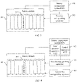
- FIG. 3 is a schematic diagram of a structure of another battery system according to an embodiment of this application.
- the battery system includes at least one battery module 301, a battery management system BMS 302, and a first fire extinguishing apparatus 303.
- a communication connection is established between the first fire extinguishing apparatus 303 and the battery management system 302.
- the first fire extinguishing apparatus 303 may communicate with the battery management system BMS 302 through a bus.
- the first fire extinguishing apparatus 303 may communicate with the battery management system BMS 302 in a wireless Bluetooth manner.
- the battery management system 303 may further supply power to the first fire extinguishing apparatus 303.
- the battery module 301 may include a plurality of cell monomers 3011.
- the battery management system BMS 302 may include a first detection apparatus 3021 and a control apparatus 3022.
- the first fire extinguishing apparatus 303 may include a fire extinguishing agent and a communications apparatus.
- the communications apparatus is configured to communicate with the battery management system BMS 302.
- the communications apparatus may include a microprocessor and a communications interface.
- the first detection apparatus 3021 may be disposed inside the battery management system BMS, or may be disposed above the plurality of cell monomers 3011. This is not specifically limited in this embodiment of this application.
- the battery management system BMS 302 may be configured to: determine a risk status of the battery module, where the risk status of the battery module may include at least one of the following: a safety valve of the battery module is in an open state and the battery module is in a thermal runaway state; and perform fire extinguishing based on the risk status of the battery module.
- an implementation process in which the battery management system BMS 302 obtains the risk status of the battery module may include: when the battery management system BMS detects, by using the first detection apparatus, that a concentration value of a flammable gas released by the battery module is greater than a first concentration value, and a value of smoke released by the battery module is greater than a first smoke value, determining that the safety valve of the battery module is in the open state; or when the battery management system BMS detects, by using the first detection apparatus, that the concentration value of the flammable gas released by the battery module is greater than a second concentration value, the value of smoke released by the battery module is greater than a second smoke value, and a temperature of the battery module is greater than a first temperature value, determining that the battery module is in the thermal runaway state.
- the battery management system BMS determines that the safety valve of the battery module is in the open state.
- the battery management system BMS determines that the battery module is in the thermal runaway state.
- an implementation process of executing a fire extinguishing policy based on the risk status of the battery module may include the following cases:
- the battery management system BMS 302 interrupts the charging/discharging process of the battery module.
- the battery management system BMS 302 may selectively cut off a relay, and control, by controlling the relay, connection or disconnection of an external power supply line of the battery module or battery pack in danger.
- early warning and fire extinguishing can be performed at an initial stage when a thermal runaway occurs in a battery, so as to well seize an optimal fire extinguishing occasion and reduce a burning probability of the battery system, thereby improving safety of the battery system.
- the battery management system BMS 302 sends control information to the first fire extinguishing apparatus, where the control information is used to indicate the first fire extinguishing apparatus 303 to spray the fire extinguishing agent on the battery module, so that the first fire extinguishing apparatus 303 may release the fire extinguishing agent based on the control information, to suppress the thermal runaway phenomenon from spreading further.
- the battery management system BMS 302 detects, by using the first detection apparatus 3021, that a cell monomer 6 is in a thermal runaway state. In this case, the battery management system BMS 302 sends control information to the first fire extinguishing apparatus 303.
- the control information includes "006, start fire extinguishing", so that the first fire extinguishing apparatus 303 can perform fire extinguishing on the cell monomer 6 based on the control information.
- the first fire extinguishing apparatus may be disposed outside the battery system, or may be disposed inside the battery system. This is not specifically limited in this embodiment of this application.
- the battery system includes a battery system housing.
- the first fire extinguishing apparatus may be disposed inside the battery system housing.
- FIG. 4 is a schematic diagram of a structure of still another battery system according to an embodiment of this application.
- the battery system includes at least one battery module 401, a battery management system BMS 402, at least one first fire extinguishing apparatus 403, and at least one second fire extinguishing apparatus 404.
- a communication connection is established between the first fire extinguishing apparatus 403 and the battery management system 402.
- the first fire extinguishing apparatus 403 may communicate with the battery management system BMS 402 through a bus.
- the first fire extinguishing apparatus 403 may communicate with the battery management system BMS 402 in a wireless Bluetooth manner.
- the battery management system 403 may further supply power to the first fire extinguishing apparatus 403.
- the battery module 401 may include a plurality of cell monomers 4011.
- the battery management system BMS 402 may include a first detection apparatus 4021 and a control apparatus 4022.
- the first fire extinguishing apparatus 403 may include a fire extinguishing agent and a communications apparatus.
- the communications apparatus is configured to communicate with the battery management system BMS 402.
- the second fire extinguishing apparatus 404 may include a fire extinguishing agent and a second detection apparatus.
- the first detection apparatus 4021 may be disposed inside the battery management system BMS, or may be disposed above the plurality of cell monomers 4011. This is not specifically limited in this embodiment of this application.
- the first detection apparatus 4021 is configured to detect data of the battery module, for example, the data may include a voltage, a current, operating temperature information, concentration of a released flammable gas, released smoke, and the like.
- the control apparatus 4022 is configured to perform processing based on the data of the battery module obtained by the first detection apparatus 4021, to obtain control information and/or an instruction.
- the control information may include: controlling the first fire extinguishing apparatus to spray the fire extinguishing agent on the battery module.
- the instruction may include: interrupting a charging/discharging process of the battery module.
- the first detection apparatus 4021 may include at least one of a temperature sensor, a gas sensor, and a smoke sensor.
- the temperature sensor is configured to detect a temperature of the battery module.
- the temperature sensor may detect the temperature of the battery module in real time.
- the gas sensor is configured to detect the concentration of a flammable and explosive gas released by the battery module.
- the smoke sensor is configured to detect a value of smoke released by the battery module.
- the battery management system BMS 402 may be configured to determine a risk status of the battery module, and execute a fire extinguishing policy based on the risk status of the battery module.
- an implementation process in which the battery management system BMS obtains the risk status of the battery module may include: if the battery management system BMS detects, by using the first detection apparatus, that a concentration value of the flammable gas released by the battery module is greater than a first concentration value, and a value of smoke released by the battery module is greater than a first smoke value, determining that a safety valve of the battery module is in an open state; or if the battery management system BMS detects, by using the first detection apparatus, that the concentration value of the flammable gas released by the battery module is greater than a second concentration value, the value of smoke released by the battery module is greater than a second smoke value, and a temperature of the battery module is greater than a first temperature value, determining that the battery module is in a thermal runaway state.
- the battery management system BMS determines that the safety valve of the battery module is in the open state.
- the battery management system BMS determines that the battery module is in the thermal runaway state.
- the implementation process of executing the fire extinguishing policy based on the risk status of the battery module may include the following case: For example, when the safety valve of the battery module is in the open state, the battery management system BMS 402 interrupts the charging/discharging process of the battery module. Specifically, the battery management system BMS 402 may selectively cut off a relay, and control, by controlling the relay, connection or disconnection of an external power supply line of the battery module or battery pack in danger. In this implementation, early warning and fire extinguishing can be performed at an initial stage when a thermal runaway occurs in a battery, so as to well seize an optimal fire extinguishing occasion and reduce a burning probability of the battery system, thereby improving safety of the battery system.
- the battery management system BMS 402 sends control information to the first fire extinguishing apparatus, where the control information is used to indicate the first fire extinguishing apparatus 403 to spray the fire extinguishing agent on the battery module, so that the first fire extinguishing apparatus 403 may release the fire extinguishing agent based on the control information, to suppress the thermal runaway phenomenon from spreading further.
- the second fire extinguishing apparatus 404 may be further used to control the fire.
- the second fire extinguishing apparatus 404 is configured to spray the fire extinguishing agent on the battery module when the battery module is in a burning state.
- the second fire extinguishing apparatus 404 includes the fire extinguishing agent and the second detection apparatus.
- the second detection apparatus may be a temperature detection apparatus.
- the temperature detection apparatus may include one of a heat sensitive line and a temperature sensitive line.
- the temperature detection apparatus may be the heat sensitive line.
- the heat sensitive line detects that the temperature of the battery module is greater than the second temperature value, for example, the second temperature value is 170°C
- the second fire extinguishing apparatus 404 is triggered to release the fire extinguishing agent.
- the fire can be suppressed from spreading to the entire battery system, and a burning probability of the battery system can be reduced.
- the temperature detection apparatus may be alternatively a detection apparatus including a temperature sensitive line.
- the detection apparatus may include a battery, an electric igniter, and a temperature sensitive line.
- the battery, the electric igniter, and the temperature sensitive line are connected in series.
- the temperature sensitive line In a room temperature state, the temperature sensitive line is in an open-circuit state.
- the temperature sensitive line In a high temperature state, the temperature sensitive line is in a short-circuit state, and the battery supplies power to the electric igniter, to trigger the second fire extinguishing apparatus 404 to release the fire extinguishing agent.
- the fire can be suppressed from spreading to the entire battery system, and a burning probability of the battery system can be reduced.
- the at least two fire extinguishing apparatuses may be disposed outside the battery system, or may be disposed inside the battery system. This is not specifically limited in this embodiment of this application.
- the battery system includes a battery system housing.
- the at least two fire extinguishing apparatuses may be disposed inside the battery system housing.
- the first fire extinguishing apparatus when the battery module is in a thermal runaway state, the first fire extinguishing apparatus is used to spray the fire extinguishing agent on the battery module.
- the second fire extinguishing apparatus is used to spray the fire extinguishing agent on the battery module.
- the battery fire can be well suppressed and the burning probability of the battery system can be reduced, thereby improving safety of the battery system.
- the battery system shown in FIG. 4 is used as an example.
- the battery system includes the battery management system BMS and the at least two fire extinguishing apparatuses.
- the at least two fire extinguishing apparatuses include at least one first fire extinguishing apparatus and at least one second fire extinguishing apparatus.
- the method steps shown in FIG. 5a should be understood as a plurality of fire extinguishing policies included in actual use of the battery system. Specifically, when the battery module is in different risk statuses, corresponding fire extinguishing policies are different. For example, when a safety valve of a battery module is in an open state, a battery management system BMS interrupts a charging/discharging process of the battery module. For another example, when the battery module is in a thermal runaway state, the battery management system BMS sends control information to the first fire extinguishing apparatus, where the control information is used to control a first fire extinguishing apparatus to spray a fire extinguishing agent on the battery module. For another example, when the battery module is in a burning state, a second fire extinguishing apparatus sprays a fire extinguishing agent on the battery module. The following describes details.
- the safety valve of the battery module is in the open state.
- the method is applied to the battery management system BMS. The method may include but is not limited to the following steps.
- Step S500a The battery management system BMS obtains a risk status of the battery module.
- Step S502a When the safety valve of the battery module is in the open state, interrupt the charging/discharging process of the battery module.
- the battery management system BMS includes a first detection apparatus and a control apparatus. Specifically, the battery management system BMS sends collected risk status data of the battery module to the control apparatus by using the first detection apparatus, and then the control apparatus receives the risk status data, and obtains the risk status of the battery module based on the risk status data.
- the safety valve of the battery module is in the open state, the charging/discharging process of the battery module is interrupted.
- step S500a to step S502a For specific implementation of step S500a to step S502a, refer to the foregoing description. Details are not described herein again. It may be understood that this method may be applied to the battery systems shown in FIG. 2a , FIG. 3, and FIG. 4 .
- early warning and fire extinguishing can be performed at an initial stage when a thermal runaway occurs in a battery, so as to well seize an optimal fire extinguishing occasion and reduce a burning probability of the battery system, thereby improving safety of the battery system.
- the battery module is in the thermal runaway state.
- the method may include but is not limited to the following steps.
- Step S500b The battery management system BMS obtains the risk status of the battery module.
- Step S502b When the battery module is in the thermal runaway state, the battery management system BMS sends the control information to the first fire extinguishing apparatus.
- Step S504b The first fire extinguishing apparatus receives the control information sent by the battery management system BMS.
- Step S506b The first fire extinguishing apparatus sprays the fire extinguishing agent on the battery module based on the control information.
- step S500b to step S506b For specific implementation of step S500b to step S506b, refer to the foregoing description. Details are not described herein again. It may be understood that this method may be applied to the battery system shown in FIG. 3 and FIG. 4 .
- the first fire extinguishing apparatus sprays the fire extinguishing agent on the battery module under control of the battery management system BMS.
- a thermal runaway phenomenon of the battery module can be well suppressed from continuously spreading, and safety of the battery system can be improved.
- both an existing battery management system BMS and the fire extinguishing apparatus include a detection apparatus, and the detection apparatus is configured to detect an operating state of the battery module.
- the detection apparatus is no longer disposed on the first fire extinguishing apparatus, the detection apparatus is integrated into the battery management system BMS, and the first fire extinguishing apparatus and the battery management system BMS are communicatively connected through a bus.
- complexity of the battery system and total costs of the system can be reduced.
- the battery module is in the burning state.
- the method may include but is not limited to the following steps.
- Step S500c When the battery module is in the burning state, the second fire extinguishing apparatus sprays the fire extinguishing agent on the battery module.
- the second fire extinguishing apparatus may include a second detection apparatus and a fire extinguishing agent.
- the second detection apparatus detects that a temperature of the battery module is greater than a second temperature value, it may be determined that the battery module is in the burning state, and the second fire extinguishing apparatus is triggered to release the fire extinguishing agent.
- the battery fire can be well suppressed and a burning probability of the battery system can be reduced, thereby improving safety of the battery system. It may be understood that this method may be applied to the battery system shown in FIG. 4 .
- the battery fire can be well suppressed and the burning probability of the battery system can be reduced, thereby improving safety of the battery system.
- FIG. 6 is a schematic diagram of a structure of a battery management system BMS according to an embodiment of this application.
- the battery management system BMS shown in FIG. 6 may include a memory 601, a processor 602, a communications interface 603, and a bus 604.
- the memory 601, the processor 602, and the communications interface 603 implement a communication connection between each other through the bus 604.
- the memory 601 may be a read only memory (Read Only Memory, ROM), a static storage device, a dynamic storage device, or a random access memory (Random Access Memory, RAM).
- the memory 601 may store a program.
- the processor 602 and the communications interface 603 are configured to perform steps performed by using the battery management system BMS in embodiments of this application.
- a risk status of a battery module is obtained by using a battery management system BMS.
- Control information is sent to a first fire extinguishing apparatus when the battery module is in a thermal runaway state.
- the control information is used to control the first fire extinguishing apparatus to spray a fire extinguishing agent on the battery module.
- the battery management system BMS interrupts the charging/discharging process of the battery module.
- the processor 602 may be a general-purpose central processing unit (Central Processing Unit, CPU), a microprocessor, an application-specific integrated circuit (Application Specific Integrated Circuit, ASIC), a graphics processing unit (graphics processing unit, GPU), or one or more integrated circuits, and is configured to execute a related program, to implement a function that needs to be performed by using the battery management system BMS in embodiments of this application, or perform the fire extinguishing method provided in the method embodiments of this application.
- CPU Central Processing Unit
- ASIC Application Specific Integrated Circuit
- GPU graphics processing unit
- the processor 602 may alternatively be an integrated circuit chip and has a signal processing capability. In an implementation process, the steps of the neural network training method in this application may be completed by using a hardware integrated logic circuit in the processor 602 or instructions in a form of software.
- the processor 602 may be a general-purpose processor, a digital signal processor (Digital Signal Processor, DSP), an application-specific integrated circuit (ASIC), a field programmable gate array (Field Programmable Gate Array, FPGA) or another programmable logic device, a discrete gate or transistor logic device, or a discrete hardware component.
- DSP Digital Signal Processor
- ASIC application-specific integrated circuit
- FPGA Field Programmable Gate Array
- the processing apparatus may implement or perform the methods, steps, and logical block diagrams that are disclosed in embodiments of this application.
- the general-purpose processor may be a microprocessor, or the processor may be any conventional processor, or the like. Steps of the method disclosed with reference to embodiments of this application may be directly executed and accomplished by a hardware decoding processor, or may be executed and accomplished by using a combination of hardware and software modules in a decoding processor.
- the software module may be located in a mature storage medium in the art, such as a random access memory, a flash memory, a read-only memory, a programmable read-only memory, an electrically erasable programmable memory, or a register.
- the storage medium is located in the memory 601, and the processor 602 reads information in the memory 601, and completes, in combination with hardware of the processor 602, a function that needs to be performed by the unit included in the battery management system in embodiments of this application, or performs the fire extinguishing method provided in the method embodiments of this application.
- the communications interface 603 uses a transceiver apparatus, for example but not for limitation, a transceiver, to implement communication between the apparatus 60 and another device or a communication network.
- a transceiver apparatus for example but not for limitation, a transceiver, to implement communication between the apparatus 60 and another device or a communication network.
- training data may be obtained through the communications interface 603 (for example, data of the battery module used in the method embodiments of this application).
- the bus 604 may include a channel through which information is transmitted between parts (for example, the memory 601, the processor 602, and the communications interface 603) of the apparatus 600.
- FIG. 7 is a schematic block diagram of a cabinet according to an embodiment of this application.
- the cabinet 70 may include a plurality of battery systems 701.
- the battery system 70 For a specific representation form of the battery system 70, refer to the foregoing description. Details are not described herein again.
- the battery system may perform different fire extinguishing policies when the battery module is in different risk statuses, thereby improving safety of the battery system.
- FIG. 8 is a schematic block diagram of an electronic device according to an embodiment of this application. As shown in FIG. 8 , the electronic device includes a battery system 800. Herein, for a specific representation form of the battery system 800, refer to the foregoing description. Details are not described herein again.
- the electronic device may be a charging apparatus in an electric vehicle, or may be an energy storage apparatus in a communications base station, or may be a lithium battery apparatus. This is not specifically limited in this embodiment of this application.
- An embodiment of this application further provides a computer-readable storage medium, where the computer-readable storage medium is configured to store a computer program for implementing the above-described fire extinguishing method for the battery system.
- the computer program enables the electronic device to perform some or all of the steps of any fire extinguishing method for the battery system described in the foregoing method embodiments.
- An embodiment of this application further provides a computer program product.
- the computer program product includes a non-transitory computer-readable storage medium storing a computer program.
- the computer program is operable to enable the electronic device to perform some or all of the steps of any convolution operation method described in the foregoing method embodiments.
- the computer-readable medium may include a computer-readable storage medium.
- the computer-readable storage medium corresponds to a tangible medium such as a data storage medium, or a communications medium including any medium that facilitates transfer of a computer program from one place to another place (for example, according to a communications protocol).
- the computer-readable medium may generally correspond to: (1) a non-transitory tangible computer-readable storage medium, or (2) a communication medium, for example, a signal or a carrier.
- the data storage medium may be any available medium that can be accessed by one or more computers or one or more processors to retrieve instructions, code, and/or data structures for implementing the technologies described in this application.
- a computer program product may include a computer-readable medium.
- the units described as separate components may or may not be physically separate, and components displayed as units may or may not be physical units.
- the components may be located at one position, or may be distributed on a plurality of network units. Some or all of the units may be selected based on actual requirements to achieve the objectives of the solutions of the embodiments.
- the functions When the functions are implemented in a form of a software functional unit and sold or used as an independent product, the functions may be stored in a computer-readable storage medium. Based on such an understanding, the technical solutions of this application essentially, or a part contributing to an existing technology, or some of the technical solutions may be implemented in a form of a software product.
- the computer software product is stored in a storage medium, and includes several instructions for instructing a computer device (which may be a personal computer, a server, or a network device) to perform all or some of the steps of the methods described in embodiments of this application.
- the foregoing storage medium includes any medium that can store program code, such as a USB flash drive, a removable hard disk, a read-only memory (Read-Only Memory, ROM), a random access memory (Random Access Memory, RAM), a magnetic disk, or an optical disc.
- program code such as a USB flash drive, a removable hard disk, a read-only memory (Read-Only Memory, ROM), a random access memory (Random Access Memory, RAM), a magnetic disk, or an optical disc.
Landscapes
- Chemical & Material Sciences (AREA)
- Chemical Kinetics & Catalysis (AREA)
- Electrochemistry (AREA)
- General Chemical & Material Sciences (AREA)
- Engineering & Computer Science (AREA)
- Manufacturing & Machinery (AREA)
- Health & Medical Sciences (AREA)
- Public Health (AREA)
- Business, Economics & Management (AREA)
- Emergency Management (AREA)
- Battery Mounting, Suspending (AREA)
- Secondary Cells (AREA)
- Fire Alarms (AREA)
Applications Claiming Priority (1)
| Application Number | Priority Date | Filing Date | Title |
|---|---|---|---|
| PCT/CN2020/072883 WO2021142812A1 (fr) | 2020-01-17 | 2020-01-17 | Système de batterie et procédé d'extinction d'incendie pour système de batterie |
Publications (2)
| Publication Number | Publication Date |
|---|---|
| EP4074384A1 true EP4074384A1 (fr) | 2022-10-19 |
| EP4074384A4 EP4074384A4 (fr) | 2023-02-22 |
Family
ID=76863295
Family Applications (1)
| Application Number | Title | Priority Date | Filing Date |
|---|---|---|---|
| EP20913294.3A Withdrawn EP4074384A4 (fr) | 2020-01-17 | 2020-01-17 | Système de batterie et procédé d'extinction d'incendie pour système de batterie |
Country Status (4)
| Country | Link |
|---|---|
| US (1) | US20220336921A1 (fr) |
| EP (1) | EP4074384A4 (fr) |
| CN (1) | CN114761091A (fr) |
| WO (1) | WO2021142812A1 (fr) |
Families Citing this family (12)
| Publication number | Priority date | Publication date | Assignee | Title |
|---|---|---|---|---|
| CN114768144A (zh) * | 2022-04-24 | 2022-07-22 | 阳光电源股份有限公司 | 一种储能系统及其消防控制方法、装置 |
| IL294100B2 (en) * | 2022-06-19 | 2024-10-01 | Yarok Advanced Solutions Ltd | Safe battery charging station mounted fire extinguishing facilitating apparatus |
| CN115105772B (zh) * | 2022-06-21 | 2022-12-27 | 中国电力科学研究院有限公司 | 一种用于储能系统的自动灭火方法及系统 |
| CN114824537B (zh) * | 2022-06-30 | 2022-09-13 | 深圳市明泰源科技有限公司 | 一种基于信息融合的磷酸铁锂电池热失控监测系统 |
| CN115487445A (zh) * | 2022-08-05 | 2022-12-20 | 南方电网调峰调频发电有限公司储能科研院 | 高压级联电池系统的消防预警方法和系统 |
| CN115337577B (zh) * | 2022-08-19 | 2023-10-13 | 江苏天合储能有限公司 | 一种液冷柜消防方法、系统及液冷柜 |
| CN115364405B (zh) * | 2022-08-24 | 2024-03-22 | 中国第一汽车股份有限公司 | 一种动力电池系统、动力电池灭火系统、方法及车辆 |
| CN115483474B (zh) * | 2022-10-24 | 2023-06-30 | 深圳市柏特瑞电子有限公司 | 一种电池充电监控系统 |
| CN115634402A (zh) * | 2022-10-25 | 2023-01-24 | 楚能新能源股份有限公司 | 一种电池消防管理系统与一种电池 |
| CN115621578B (zh) * | 2022-11-15 | 2023-03-31 | 深圳海润新能源科技有限公司 | 一种电池簇的联动控制系统及方法 |
| CN116808477A (zh) * | 2023-06-29 | 2023-09-29 | 宁夏宝丰昱能科技有限公司 | 电池舱灭火方法、系统和设备 |
| CN116706296B (zh) * | 2023-08-04 | 2023-10-27 | 江苏舒茨测控设备股份有限公司 | 一种电池系统热失控监测方法及装置 |
Family Cites Families (14)
| Publication number | Priority date | Publication date | Assignee | Title |
|---|---|---|---|---|
| DE102013006758A1 (de) * | 2013-04-19 | 2014-10-23 | Daimler Ag | Batterieanordnung und Verfahren zum Betreiben einer Batterieanordnung |
| CN106066457A (zh) * | 2016-05-25 | 2016-11-02 | 烟台创为新能源科技有限公司 | 一种电池热失控检测系统及其检测方法 |
| CN105904992B (zh) * | 2016-06-07 | 2018-08-24 | 烟台创为新能源科技有限公司 | 一种电动汽车的电池监控管理系统及其监控方法 |
| CN106345085A (zh) * | 2016-09-30 | 2017-01-25 | 江苏鸿鹄电子科技有限公司 | 一种新能源汽车动力电池安全系统 |
| CN106571503A (zh) * | 2016-11-11 | 2017-04-19 | 华中科技大学 | 一种电动汽车电池模组热失控安全消防系统及方法 |
| CN106581896A (zh) * | 2017-01-19 | 2017-04-26 | 安徽中涣防务装备技术股份有限公司 | 一种新能源动力电池箱灭火系统及其灭火方法 |
| KR102220902B1 (ko) * | 2017-01-26 | 2021-02-26 | 삼성에스디아이 주식회사 | 소화시스템을 포함하는 배터리 팩 |
| KR102437707B1 (ko) * | 2017-04-07 | 2022-08-29 | 현대자동차주식회사 | 차량용 배터리 화재 진화 시스템 및 제어방법 |
| CN109316687B (zh) * | 2017-07-31 | 2021-05-11 | 华为技术有限公司 | 一种电池系统的灭火方法及电池系统 |
| CN107768749B (zh) * | 2017-09-22 | 2020-02-14 | 北京精密机电控制设备研究所 | 一种具备自动灭火功能的电池箱 |
| EP3466494A1 (fr) * | 2017-10-05 | 2019-04-10 | aentron GmbH | Module de batterie doté d'un dispositif de protection contre l'incendie |
| CN109432634B (zh) * | 2018-10-08 | 2020-08-28 | 中国科学技术大学 | 一种集装箱式锂离子电池储能系统的消防方法 |
| CN109786867A (zh) * | 2018-12-07 | 2019-05-21 | 安徽理工大学 | 锂离子电池包液氮保护技术 |
| CN109985335A (zh) * | 2019-04-01 | 2019-07-09 | 北京工业大学 | 一种新能源汽车用锂离子电池的分离式自动灭火系统 |
-
2020
- 2020-01-17 WO PCT/CN2020/072883 patent/WO2021142812A1/fr not_active Ceased
- 2020-01-17 CN CN202080083135.2A patent/CN114761091A/zh active Pending
- 2020-01-17 EP EP20913294.3A patent/EP4074384A4/fr not_active Withdrawn
-
2022
- 2022-07-06 US US17/858,324 patent/US20220336921A1/en not_active Abandoned
Also Published As
| Publication number | Publication date |
|---|---|
| US20220336921A1 (en) | 2022-10-20 |
| EP4074384A4 (fr) | 2023-02-22 |
| CN114761091A (zh) | 2022-07-15 |
| WO2021142812A1 (fr) | 2021-07-22 |
Similar Documents
| Publication | Publication Date | Title |
|---|---|---|
| US20220336921A1 (en) | Battery system and fire extinguishing method for battery system | |
| EP4443616B1 (fr) | Système de stockage d'énergie et procédé de commande associé | |
| KR20220004854A (ko) | 소화장치를 포함하는 배터리 팩 | |
| US20250226502A1 (en) | Battery pack including fire suppression means | |
| US20200313245A1 (en) | Power battery pack safety prevention and control system for electric vehicle and control method | |
| CN110911772A (zh) | 一种动力锂离子电池热失控早期预警方法 | |
| CN110828935A (zh) | 一种锂离子电池电动汽车安全防护方法 | |
| CN114699676A (zh) | 储能系统及其控制方法 | |
| JP2016192261A (ja) | 蓄電システム、制御装置、二次電池の消火方法およびプログラム | |
| CN113809441A (zh) | 一种电池包热失控控制方法、装置、储能柜和存储介质 | |
| CN112768819A (zh) | 一种高消防安全的储能电池包与储能电池集装箱 | |
| Yan et al. | Research on overcharge mitigations and thermal runaway risk of 18650 lithium-ion batteries | |
| CN114191750A (zh) | 锂电池储能系统钝化灭火抑爆系统及方法 | |
| CN113488716A (zh) | 一种储能电站锂离子电池的降温灭火方法及装置 | |
| KR20200087956A (ko) | 화재확산 방지기능이 강화된 외장 컨테이너형 에너지저장장치시스템 | |
| CN115548480B (zh) | 电池系统及电池系统的控制方法 | |
| CN118925153A (zh) | 一种储能电站灭火控制方法 | |
| CN117547765A (zh) | 电池模组、电化学储能电站分布式自触发电池热失控抑制装置及方法 | |
| CN114377321A (zh) | 电池组件的消防方法、电池组件的消防装置和储能设备 | |
| TWM642058U (zh) | 多階段消防的儲能系統 | |
| CN206332134U (zh) | 一种新能源汽车动力电池安全系统 | |
| CN109088029B (zh) | 锂离子电池及应用锂离子电池的装置 | |
| CN207868322U (zh) | 电动车用动力电池组安全防控系统 | |
| Barelli et al. | Oxygen reduction approaches for fire protection to increase grid Li-ion BESS safety | |
| CN114028747B (zh) | 热失控抑制方法、装置、系统及存储介质 |
Legal Events
| Date | Code | Title | Description |
|---|---|---|---|
| STAA | Information on the status of an ep patent application or granted ep patent |
Free format text: STATUS: THE INTERNATIONAL PUBLICATION HAS BEEN MADE |
|
| PUAI | Public reference made under article 153(3) epc to a published international application that has entered the european phase |
Free format text: ORIGINAL CODE: 0009012 |
|
| STAA | Information on the status of an ep patent application or granted ep patent |
Free format text: STATUS: REQUEST FOR EXAMINATION WAS MADE |
|
| 17P | Request for examination filed |
Effective date: 20220714 |
|
| AK | Designated contracting states |
Kind code of ref document: A1 Designated state(s): AL AT BE BG CH CY CZ DE DK EE ES FI FR GB GR HR HU IE IS IT LI LT LU LV MC MK MT NL NO PL PT RO RS SE SI SK SM TR |
|
| A4 | Supplementary search report drawn up and despatched |
Effective date: 20230123 |
|
| RIC1 | Information provided on ipc code assigned before grant |
Ipc: H01M 50/383 20210101ALI20230117BHEP Ipc: A62C 3/07 20060101ALI20230117BHEP Ipc: H01M 10/48 20060101ALI20230117BHEP Ipc: A62C 3/16 20060101AFI20230117BHEP |
|
| DAV | Request for validation of the european patent (deleted) | ||
| DAX | Request for extension of the european patent (deleted) | ||
| STAA | Information on the status of an ep patent application or granted ep patent |
Free format text: STATUS: THE APPLICATION IS DEEMED TO BE WITHDRAWN |
|
| 18D | Application deemed to be withdrawn |
Effective date: 20230822 |