EP4074385B1 - Entraîneur elliptique réglable - Google Patents
Entraîneur elliptique réglable Download PDFInfo
- Publication number
- EP4074385B1 EP4074385B1 EP21193383.3A EP21193383A EP4074385B1 EP 4074385 B1 EP4074385 B1 EP 4074385B1 EP 21193383 A EP21193383 A EP 21193383A EP 4074385 B1 EP4074385 B1 EP 4074385B1
- Authority
- EP
- European Patent Office
- Prior art keywords
- sliding rail
- connecting piece
- elliptical trainer
- connection point
- adjustable elliptical
- Prior art date
- Legal status (The legal status is an assumption and is not a legal conclusion. Google has not performed a legal analysis and makes no representation as to the accuracy of the status listed.)
- Active
Links
Images


Classifications
-
- A—HUMAN NECESSITIES
- A63—SPORTS; GAMES; AMUSEMENTS
- A63B—APPARATUS FOR PHYSICAL TRAINING, GYMNASTICS, SWIMMING, CLIMBING, OR FENCING; BALL GAMES; TRAINING EQUIPMENT
- A63B22/00—Exercising apparatus specially adapted for conditioning the cardio-vascular system, for training agility or co-ordination of movements
- A63B22/06—Exercising apparatus specially adapted for conditioning the cardio-vascular system, for training agility or co-ordination of movements with support elements performing a rotating cycling movement, i.e. a closed path movement
- A63B22/0664—Exercising apparatus specially adapted for conditioning the cardio-vascular system, for training agility or co-ordination of movements with support elements performing a rotating cycling movement, i.e. a closed path movement performing an elliptic movement
-
- A—HUMAN NECESSITIES
- A63—SPORTS; GAMES; AMUSEMENTS
- A63B—APPARATUS FOR PHYSICAL TRAINING, GYMNASTICS, SWIMMING, CLIMBING, OR FENCING; BALL GAMES; TRAINING EQUIPMENT
- A63B22/00—Exercising apparatus specially adapted for conditioning the cardio-vascular system, for training agility or co-ordination of movements
- A63B22/0015—Exercising apparatus specially adapted for conditioning the cardio-vascular system, for training agility or co-ordination of movements with an adjustable movement path of the support elements
-
- A—HUMAN NECESSITIES
- A63—SPORTS; GAMES; AMUSEMENTS
- A63B—APPARATUS FOR PHYSICAL TRAINING, GYMNASTICS, SWIMMING, CLIMBING, OR FENCING; BALL GAMES; TRAINING EQUIPMENT
- A63B22/00—Exercising apparatus specially adapted for conditioning the cardio-vascular system, for training agility or co-ordination of movements
- A63B22/0002—Exercising apparatus specially adapted for conditioning the cardio-vascular system, for training agility or co-ordination of movements involving an exercising of arms
- A63B22/001—Exercising apparatus specially adapted for conditioning the cardio-vascular system, for training agility or co-ordination of movements involving an exercising of arms by simultaneously exercising arms and legs, e.g. diagonally in anti-phase
-
- A—HUMAN NECESSITIES
- A63—SPORTS; GAMES; AMUSEMENTS
- A63B—APPARATUS FOR PHYSICAL TRAINING, GYMNASTICS, SWIMMING, CLIMBING, OR FENCING; BALL GAMES; TRAINING EQUIPMENT
- A63B22/00—Exercising apparatus specially adapted for conditioning the cardio-vascular system, for training agility or co-ordination of movements
- A63B22/06—Exercising apparatus specially adapted for conditioning the cardio-vascular system, for training agility or co-ordination of movements with support elements performing a rotating cycling movement, i.e. a closed path movement
- A63B22/0664—Exercising apparatus specially adapted for conditioning the cardio-vascular system, for training agility or co-ordination of movements with support elements performing a rotating cycling movement, i.e. a closed path movement performing an elliptic movement
- A63B2022/0676—Exercising apparatus specially adapted for conditioning the cardio-vascular system, for training agility or co-ordination of movements with support elements performing a rotating cycling movement, i.e. a closed path movement performing an elliptic movement with crank and handles being on the same side of the exercising apparatus with respect to the frontal body-plane of the user, e.g. crank and handles are in front of the user
-
- A—HUMAN NECESSITIES
- A63—SPORTS; GAMES; AMUSEMENTS
- A63B—APPARATUS FOR PHYSICAL TRAINING, GYMNASTICS, SWIMMING, CLIMBING, OR FENCING; BALL GAMES; TRAINING EQUIPMENT
- A63B22/00—Exercising apparatus specially adapted for conditioning the cardio-vascular system, for training agility or co-ordination of movements
- A63B22/06—Exercising apparatus specially adapted for conditioning the cardio-vascular system, for training agility or co-ordination of movements with support elements performing a rotating cycling movement, i.e. a closed path movement
- A63B22/0664—Exercising apparatus specially adapted for conditioning the cardio-vascular system, for training agility or co-ordination of movements with support elements performing a rotating cycling movement, i.e. a closed path movement performing an elliptic movement
- A63B2022/0676—Exercising apparatus specially adapted for conditioning the cardio-vascular system, for training agility or co-ordination of movements with support elements performing a rotating cycling movement, i.e. a closed path movement performing an elliptic movement with crank and handles being on the same side of the exercising apparatus with respect to the frontal body-plane of the user, e.g. crank and handles are in front of the user
- A63B2022/0682—Exercising apparatus specially adapted for conditioning the cardio-vascular system, for training agility or co-ordination of movements with support elements performing a rotating cycling movement, i.e. a closed path movement performing an elliptic movement with crank and handles being on the same side of the exercising apparatus with respect to the frontal body-plane of the user, e.g. crank and handles are in front of the user with support elements being cantilevered, i.e. the elements being supported only on one side without bearing on tracks on the floor below the user
-
- A—HUMAN NECESSITIES
- A63—SPORTS; GAMES; AMUSEMENTS
- A63B—APPARATUS FOR PHYSICAL TRAINING, GYMNASTICS, SWIMMING, CLIMBING, OR FENCING; BALL GAMES; TRAINING EQUIPMENT
- A63B22/00—Exercising apparatus specially adapted for conditioning the cardio-vascular system, for training agility or co-ordination of movements
- A63B22/0015—Exercising apparatus specially adapted for conditioning the cardio-vascular system, for training agility or co-ordination of movements with an adjustable movement path of the support elements
- A63B22/0023—Exercising apparatus specially adapted for conditioning the cardio-vascular system, for training agility or co-ordination of movements with an adjustable movement path of the support elements the inclination of the main axis of the movement path being adjustable, e.g. the inclination of an endless band
-
- A—HUMAN NECESSITIES
- A63—SPORTS; GAMES; AMUSEMENTS
- A63B—APPARATUS FOR PHYSICAL TRAINING, GYMNASTICS, SWIMMING, CLIMBING, OR FENCING; BALL GAMES; TRAINING EQUIPMENT
- A63B22/00—Exercising apparatus specially adapted for conditioning the cardio-vascular system, for training agility or co-ordination of movements
- A63B22/20—Exercising apparatus specially adapted for conditioning the cardio-vascular system, for training agility or co-ordination of movements using rollers, wheels, castors or the like, e.g. gliding means, to be moved over the floor or other surface, e.g. guide tracks, during exercising
- A63B22/201—Exercising apparatus specially adapted for conditioning the cardio-vascular system, for training agility or co-ordination of movements using rollers, wheels, castors or the like, e.g. gliding means, to be moved over the floor or other surface, e.g. guide tracks, during exercising for moving a support element in reciprocating translation, i.e. for sliding back and forth on a guide track
- A63B22/205—Exercising apparatus specially adapted for conditioning the cardio-vascular system, for training agility or co-ordination of movements using rollers, wheels, castors or the like, e.g. gliding means, to be moved over the floor or other surface, e.g. guide tracks, during exercising for moving a support element in reciprocating translation, i.e. for sliding back and forth on a guide track in a substantially vertical plane, e.g. for exercising against gravity
-
- A—HUMAN NECESSITIES
- A63—SPORTS; GAMES; AMUSEMENTS
- A63B—APPARATUS FOR PHYSICAL TRAINING, GYMNASTICS, SWIMMING, CLIMBING, OR FENCING; BALL GAMES; TRAINING EQUIPMENT
- A63B2225/00—Miscellaneous features of sport apparatus, devices or equipment
- A63B2225/09—Adjustable dimensions
- A63B2225/096—Adjustable dimensions automatically adjusted according to anthropometric data of the user
Definitions
- the present disclosure relates to the technical field of sports fitness equipment, and in particular, to an adjustable elliptical trainer.
- a pedal lifting mechanism for use in an elliptical trainer includes a base, a lift bracket pivotally connected with the base for supporting pedals of the elliptical trainer thereon, and an inclination adjusting device mounted in front of the lift bracket.
- a driving rod of the inclination adjusting device is changed in its length by the driver, such that a frame of the inclination adjusting device, which is pivotally connected between the driving rod and the lift bracket, is driven by the driving rod to move the lift bracket upwards and downwards relative to the base.
- the inclination angle of each of two pedals of the elliptical trainer is adjusted to change the paths of the pedals of the elliptical trainer.
- Embodiments of the present disclosure provide an adjustable elliptical trainer including: a body; a sliding rail and a connecting piece, wherein, the sliding rail has one end rotatably connected to the body around an axis and an other end detachably connected to the body by the connecting piece along a longitudinal extension direction of the sliding rail; and a movement mechanism including a sliding part matched with the sliding rail, the sliding part being provided on the sliding rail and being slidable along the sliding rail; wherein the axis is perpendicular to the longitudinal extension direction of the sliding rail, a first connection point is provided at a joint between the connecting piece and the sliding rail, and a second connection point is provided at a joint between the connecting piece and the body, the connecting piece is configured to be movable relative to the sliding rail and/or the body to adjust a distance between the first connection point and the second connection point, so as to adjust an angle at which the sliding rail is inclined to the body; wherein the connecting piece is a fixing plate, one end of the fixing plate is fixedly connected
- the sliding rail and the fixing plate are integrally formed.
- the connecting piece is a telescopic rod
- the telescopic rod has a fixed end and a movable end
- the movable end is configured to be able to adjust a length that extends out of the fixed end
- the fixed end is connected to the body
- the movable end is connected to the sliding rail.
- it further includes: a motor configured to be able to drive the movable end to be extended and retracted relative to the fixed end.
- the body includes a fixing frame and an upright column inclined to the fixing frame, and the one end of the sliding rail is rotatably connected to one of the fixing frame and the upright column, and the other end of the sliding rail is connected to the other of the fixing frame and the upright column by the connecting piece.
- the movement mechanism includes a handle lever, a swing lever, and a crank, both ends of the crank are respectively rotatably connected to the fixing frame and the swing lever, and the handle lever is fixedly connected to the swing lever.
- the movement mechanism further includes a first link, and both ends of the first link are respectively rotatably connected to the upright column and the swing lever.
- the movement mechanism further includes a track plate and a slider, the track plate is fixedly connected to the upright column, a guide groove is formed on the track plate, one end of the slider is connected to the swing lever, and the an other end of the slider is received in the guide groove and is slidable along the guide groove.
- the movement mechanism further includes a second link, a stand pipe, and a pedal; one end of the second link is rotatably connected to the swing lever, and an other end of the second link is fixedly connected to the pedal; and, one end of the stand pipe is connected to the second link, and the sliding part is provided at an other end of the stand pipe.
- one end of the sliding rail is rotatably connected to the body and the other end of the sliding rail is detachably connected to the body by the connecting piece, the first connection point is provided at a joint between the connecting piece and the sliding rail and the second connection point is provided at a joint between the connecting piece and the body, and the connecting piece is movable relative to the sliding rail and/or the body to adjust a distance between the first connection point and the second connection point.
- the end of the slide rail connected to the connecting piece will rotate relative to the end of the slide rail connected to the body. In this way, the angle at which the slide rail is inclined to the body also changes.
- the adjustable elliptical trainer in the present disclosure has a simple structure, and the angle at which the slide rail is inclined to the body is easily adjusted, which can well meet the requirements of users with different exercise intensities.
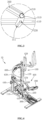
- FIG. 1 is a schematic diagram of an overall structure of an adjustable elliptical trainer provided by an embodiment of the present disclosure
- FIG. 2 is a schematic structural view of the adjustable elliptical trainer provided by an embodiment of the present disclosure from one perspective.
- an embodiment of the present disclosure provides an adjustable elliptical trainer 10.
- the adjustable elliptical trainer 10 includes a body 100, a sliding rail 200, a connecting piece 300, and a movement mechanism 400.
- the body 100 is fixed, and both ends of the sliding rail 200 are respectively fixed at different positions of the body 100.
- one end of the sliding rail 200 is rotatably connected to the body 100, and the other end of the sliding rail 200 is detachably connected to the body 100 by the connecting piece 300.
- the connecting piece 300 By adjusting the connecting piece 300, an angle at which the sliding rail 200 is inclined to the body 100 can be changed.
- the movement mechanism 400 includes a sliding part 410 that matches the sliding rail 200.
- the sliding part 410 is provided on the sliding rail 200 and is slidable along the sliding rail 200. In this way, the movement mechanism 400 will slide on the slide rail 200 along with the slide portion 410 when the user uses it.
- the angle at which the slide rail 200 is inclined to the body 100 changes, the motion trajectory of the motion mechanism 400 is also change, and the effect reflected to the user is that the exercise intensity has changed. As a result, it is possible to meet the exercise requirements of users with different exercise intensities by adjusting the angle at which the sliding rail 200 is inclined to the body 100.
- the body 100 is a fixed component in the adjustable elliptical trainer 10, and is used to install, locate, and connect other components or assemblies in the adjustable elliptical trainer 10, such as the sliding rail 200, the movement mechanism 400, and the like. Structure, shape and size of the body 100 are not limited, and can be flexibly adjusted according to the design requirements of the adjustable elliptical trainer 10.
- the sliding rail 200 is a component of the adjustable elliptical trainer 10 that matches with the movement mechanism 400.
- the user drives the movement mechanism 400 to move on the sliding rail 200 to achieve the effect of exercise. It is understandable that by adjusting the angle at which the sliding rail 200 is inclined to the body 100, the movement trajectory of the movement mechanism 400 is also changed, and the effect reflected to the user is that the exercise intensity has changed. Therefore, in the embodiments of the present disclosure, through this principle, the adjustable elliptical trainer 10 can meet the requirements of users with different exercise intensities.
- a first connection point 210 is provided at a joint between the connecting piece 300 and the sliding rail 200
- a second connection point 220 is provided at a joint between the connecting piece 300 and the body 100.
- the connecting piece 300 is configured to be movable relative to the sliding rail 200 and/or the body 100 to adjust the distance between the first connection point 210 and the second connection point 220, thereby adjusting the angle at which the sliding rail 200 is inclined to the body 100.
- the connecting piece 300 can be provided with multiple connection structures at different positions, and the position of the connecting piece 300 can be adjusted so that it is connected to the sliding rail 200 and the body 100 by the connection structures at different positions, and thus the distance between the first connection point 210 and the second connection point 220 will change.
- the connecting piece 300 includes two different units. One unit is connected to the sliding rail 200, and the other unit is connected to the body 100, and the two units are movable relative to each other. In this way, after the two units are moved relative to each other, the distance between the first connection point 210 and the second connection point 220 will change.
- the connecting piece 300 when the adjustable elliptical trainer 10 is in use, that is, when the movement mechanism 400 is in a motion state, the connecting piece 300 is fixedly connected to the sliding rail 200 and the body 100. At this time, the distance between the first connection point 210 and the second connection point 220 is also kept relatively fixed to maintain the stability of the sliding rail 200, to ensure that the movement mechanism 400 can move normally, and to ensure the safety of the user.
- the adjustable elliptical trainer 10 is in a disabled state, that is, when the movement mechanism 400 is in a non-motion state, the connecting piece 300 can be adjusted to change the distance between the first connection point 210 and the second connection point 220.
- one end of the sliding rail 200 is rotatably connected to the body 100 and the other end of the sliding rail 200 is detachably connected to the body 100 by the connecting piece 300, the first connection point 210 is provided at a joint between the connecting piece 300 and the sliding rail 200 and the second connection point 220 is provided at a joint between the connecting piece 300 and the body 100, and the connecting piece 300 is able to adjust a distance between the first connection point 210 and the second connection point 220.
- the end of the slide rail 200 connected to the connecting piece 300 will rotate relative to the end of the slide rail 200 connected to the body 100. In this way, the angle at which the slide rail 200 is inclined to the body 100 also changes.
- the adjustable elliptical trainer 10 in the present disclosure has a simple structure, and the angle at which the slide rail 200 is inclined to the body 100 is easily adjusted, which can well meet the requirements of users with different exercise intensities.
- FIG. 2 is a schematic structural view of an adjustable elliptical trainer 10 provided by an embodiment of the present disclosure from one perspective
- FIG. 3 is a partial enlarged schematic diagram at A in FIG. 2 .
- multiple connecting structures can be provided at different positions on the connecting piece 300, and the position of the connecting piece 300 can be adjusted so that it is respectively connected to the sliding rail 200 and the body 100 by the connecting structures at different positions, and thus the distance between the first connection point 210 and the second connection point 220 will change.
- the connecting piece 300 is a fixing plate 310, one end of the fixing plate 310 is fixedly connected to the sliding rail 200, and a plurality of fixing holes 311 are provided in the fixing plate 310, distances between each of the fixing holes 311 and the first connection point 210 are different, and the other end of the fixing plate 310 is detachably connected to the body 100 by respective fixing holes 311.
- the connection between the fixing plate 310 and the body 100 can be realized with the help of the connecting piece 300 such as a screw.
- threaded holes are provided on the body 100 at the positions respectively corresponding to the fixing holes 311, and screws pass through the respective fixing holes 311 and then are screwed into the threaded holes to achieve fixation.
- the number of fixing holes 311 can be flexibly set according to the number of gears that need to be adjusted, and it is not specifically limited here. The more the number of fixing holes 311, the smaller the angle change of the sliding rail 200 between two adjacent gears, and the finer the adjustment range. The smaller the number of fixing holes 311, the greater the angle change of the sliding rail 200 between two adjacent gears, and the greater the adjustment range.
- one end of the fixing plate 310 can be fixedly connected to the body 100, and the other end of the fixing plate 310 can be detachably connected to the sliding rail 200 by the respective fixing holes 311. At this time, the adjustment principle is the same and will not be repeated here.
- the fixing plate 310 and the sliding rail 200 can be connected by common connection manner used in the art including welding, riveting, and bonding.
- the sliding rail 200 and the fixing plate 310 may also be integrally formed.
- the integrally formed connection method is adopted to make the connection between the sliding rail 200 and the fixing member tighter, and the processing of the sliding rail 200 and the fixing member simpler and more convenient.
- the fixing plate 310 and the body 100 can also be integrally formed.
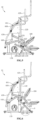
- FIG. 5 is a schematic structural diagram of an adjustable elliptical trainer provided by an embodiment of the present disclosure from another perspective, in which an angle between the sliding rail 200 and the body 100 is 30°;
- FIG. 6 is a schematic structural diagram of an adjustable elliptical trainer provided by an embodiment of the present disclosure from yet another perspective, in which an angle between the sliding rail 200 and the body 100 is 43°;
- FIG. 7 is a partial enlarged schematic diagram at B in FIG. 6 .
- the connecting piece 300 may also include two different units, one unit is connected to the sliding rail 200, and the other unit is connected to the body 100, and the two units are movable relative to each other. In this way, after the two units are moved relative to each other, the distance between the first connection point 210 and the second connection point 220 will change.
- the connecting piece 300 is a telescopic rod 320
- the telescopic rod 320 has a fixed end 321 and a movable end 322, the movable end 322 is configured to be able to adjust the length that extends out of the fixed end 321, and the fixed end 321 is connected to the body 100, and the movable end 322 is connected to the sliding rail 200.
- the telescopic rod 320 can adopt a structure such as a push rod and an oil cylinder. When the telescopic rod 320 is extended, the distance between the first connection point 210 and the second connection point 220 will increase, and the angle at which the sliding rail 200 is inclined to the body 100 will also increase.
- the length of the telescopic rod 320 can be continuously adjusted in multiple gears, and the angle at which the sliding rail 200 is inclined to the body 100 can be continuously adjusted within a certain range.
- the angle at which the sliding rail 200 is inclined to the body 100 can be continuously adjusted between 30° and 43°. In other embodiments, the angle at which the sliding rail 200 is inclined to the body 100 can be adjusted further within a larger or smaller range.
- the fixed end 321 may be connected to the sliding rail 200, and the movable end 322 may be connected to the body 100. At this time, the adjustment principle is the same and will not be repeated here.
- the adjustable elliptical trainer 10 also includes a motor, which is configured to drive the movable end 322 to be extended and retracted relative to fixed end 321. At this time, there is no need to manually adjust the length of the movable end 322 extending out of the fixed end 321, just control the motor to start or stop, and the telescopic rod 320 can be driven by the power of the motor to adjust the length, and then adjust the angle at which the sliding rail 200 is inclined to the body 100. The adjustment is simpler and more convenient.
- speed of the movable end 322 of the telescopic rod 320 can also be changed. If the power output of the motor is large, the movable end will extend and retract faster, and the angle at which the sliding rail 200 is inclined to the body 100 will be faster. If the power output of the motor is small, the movable end will extend and retract slowly, and the angle at which the sliding rail 200 is inclined to the body 100 will be slower. The control and adjustment are more precise.
- the body 100 includes a fixing frame 110 and an upright column 120 inclined to the fixing frame 110, one end of the sliding rail 200 is rotatably connected to one of the fixing frame 110 and the upright column 120, and the other end of the sliding rail 200 is connected to the other of the connecting piece 300 and the fixing frame 110 and the upright column 120 by the connecting piece 300.
- the sliding rail 200 adopts the sliding rail 200, which allows the movement mechanism 400 to slide along the sliding rail 200. As shown in FIGS.
- one end of the sliding rail 200 is rotatably connected to the upright column 120, and the other end of the sliding rail 200 is connected to the fixing frame 110 by the connecting piece 300.
- one end of the sliding rail 200 is rotatably connected to the fixing frame 110, and the other end of the sliding rail 200 is connected to the upright column 120 by the connecting piece 300.
- the movement mechanism 400 in order to allow the user to exercise normally, in some embodiments, includes a handle lever 420, a swing lever 430, and a crank 440. Both ends of the crank 440 are respectively rotatably connected to the fixing frame 110 and the swing lever 430, and the handle lever 420 is fixedly connected to the swing lever 430. Further, the movement mechanism 400 further includes a first link 450, and both ends of the first link 450 are respectively rotatably connected to the upright column 120 and the swing lever 430.
- the handle lever 420 is rotatably connected to the crank 440 by the swing lever 430, and the crank 440 is rotatably connected to the fixing frame 110, on the other hand, the swing lever 430 is rotatably connected to the upright column 120 by the first link 450. That is, the handle lever can drive the crank 440 and the fixing frame 110 to move relative to each other, and at the same time drive the first link 450 and the upright column 120 to move relative to each other. At this time, the user can reciprocate the handle lever back and forth to realize the exercise of the arm.
- the movement mechanism 400 further includes a track plate 460 and a slider.
- the track plate 460 is fixedly connected to the upright column 120, the track plate 460 is provided with a guide groove 461, and one end of the slider is connected to the swing lever 430, and the other end of the slider is received in the guide groove 461 and can slide along the guide groove 461.
- the handle lever 420 is rotatably connected to the crank 440 by the swing lever 430, and the crank 440 is rotatably connected to the fixing frame 110.
- the swing lever 430 is connected to the track plate 460 by the slider.
- the handle lever can drive the crank 440 and the fixing frame 110 to move relative to each other, and at the same time drive slider to slide in the guide groove 461 of the track plate 460. At this time, the user can reciprocate the handle lever back and forth to realize the exercise of the arm.
- the movement mechanism 400 further includes a second link 470, a stand pipe 480, and a pedal 490.
- One end of the second link 470 is rotatably connected to the swing lever 430, and the other end of the second link 470 is fixedly connected to the pedal 490, one end of the stand pipe 480 is connected to the second link 470, and the sliding part 410 is located at the other end of the stand pipe 480.
- the pedal 490 can drive the second link 470 and the swing lever 430 to move relative to each other, and at the same time drive the sliding part 410 to slide on the sliding rail 200. At this time, the user can step on the pedal 490 to perform back and forth reciprocating motions to exercise the legs.
- the number of structures such as the sliding rail 200, connecting piece 300 in the adjustable elliptical trainer 10, and the sliding part 410, handle lever 420, swing lever 430, crank 440, first link 450, track plate 460, second link 470, stand pipe 480, pedal 490 in the movement mechanism 400, etc. are two groups, and the two groups of the above-mentioned components are respectively arranged on both sides of the upright column 120, so that the user can exercise both hands and legs.
- the two groups of components are opposed to each other, that is, the movement between the two groups of components can be asynchronous, so that the user's hands and legs can perform asynchronous staggered movements during use.
- One end of the sliding rail 200 is rotatably connected to the body 100 around an axis, the other end of the sliding rail 200 is detachably connected to the body 100 by the connecting piece 300, the first connection point 210 is provided at a joint between the connecting piece 300 and the sliding rail 200 and the second connection point 220 is provided at a joint between the connecting piece 300 and the body 100, and the connecting piece 300 is movable relative to the sliding rail 200 and/or the body 100 so as to adjust a distance between the first connection point 210 and the second connection point 220.
- the end of the slide rail 200 connected to the connecting piece 300 will rotate relative to the end of the slide rail 200 connected to the body 100. In this way, the angle at which the slide rail 200 is inclined to the body 100 also changes.
- the relative positions between the various mechanisms can be flexibly adjusted, which facilitates the folding and storage by users, saves the space occupied by the adjustable elliptical trainer 10, maximizes space utilization, and facilitates storage and transportation.
Landscapes
- Health & Medical Sciences (AREA)
- Cardiology (AREA)
- Vascular Medicine (AREA)
- General Health & Medical Sciences (AREA)
- Physical Education & Sports Medicine (AREA)
- Rehabilitation Tools (AREA)
Claims (9)
- Appareil d'entraînement elliptique réglable, comprenant :un corps (100) ;un rail coulissant (200) et une pièce de liaison (300), dans lequel le rail coulissant a une extrémité reliée de manière rotative au corps autour d'un axe et une autre extrémité reliée de manière détachable au corps par la pièce de liaison le long d'une direction d'extension longitudinale du rail coulissant ; etun mécanisme de mouvement (400) comprenant une partie coulissante coïncidant avec le rail coulissant, la partie coulissante étant prévue sur le rail coulissant et pouvant coulisser le long du rail coulissant ;dans lequel l'axe est perpendiculaire à la direction d'extension longitudinale du rail coulissant, un premier point de liaison est prévu au niveau d'une articulation entre la pièce de liaison et le rail coulissant, et un deuxième point de liaison est prévu au niveau d'une articulation entre la pièce de liaison et le corps, la pièce de liaison est configurée pour être mobile par rapport au rail coulissant et/ou au corps pour régler une distance entre le premier point de liaison et le deuxième point de liaison, de manière à régler un angle auquel le rail coulissant est incliné vers le corps ;caractérisé en ce quela pièce de liaison est une plaque de fixation (310), une extrémité de la plaque de fixation est reliée de manière fixe au rail coulissant, et une pluralité de trous de fixation (311) sont prévus dans la plaque de fixation, et des distances entre chacun des trous de fixation et le premier point de liaison sont différentes, une autre extrémité de la plaque de fixation est reliée de manière détachable au corps par des trous de fixation respectifs.
- Appareil d'entraînement elliptique réglable selon la revendication 1, dans lequel le rail coulissant et la plaque de fixation sont formés d'un seul tenant.
- Appareil d'entraînement elliptique réglable selon la revendication 1, dans lequel la pièce de liaison est une tige télescopique (320), la tige télescopique a une extrémité fixe (321) et une extrémité mobile (322), et l'extrémité mobile est configurée pour être capable de régler une longueur qui s'étend hors de l'extrémité fixe, l'extrémité fixe est reliée au corps, et l'extrémité mobile est reliée au rail coulissant.
- Appareil d'entraînement elliptique réglable selon la revendication 3, comprenant en outre : un moteur configuré pour être capable d'entraîner l'extrémité mobile pour qu'elle soit étendue et rétractée par rapport à l'extrémité fixe.
- Appareil d'entraînement elliptique réglable selon la revendication 1, dans lequel le corps comprend un cadre de fixation (110) et une colonne droite (120) inclinée vers le cadre de fixation, et l'extrémité du rail coulissant est reliée de manière rotative à l'un parmi le cadre de fixation et la colonne droite, et l'autre extrémité du rail coulissant est reliée à l'autre parmi le cadre de fixation et la colonne droite par la pièce de liaison.
- Appareil d'entraînement elliptique réglable selon la revendication 5, dans lequel le mécanisme de mouvement comprend un levier de poignée (420), un levier pivotant (430) et une manivelle (440), les deux extrémités de la manivelle sont respectivement reliées de manière rotative au cadre de fixation et au levier pivotant, et le levier de poignée est relié de manière fixe au levier pivotant.
- Appareil d'entraînement elliptique réglable selon la revendication 6, dans lequel le mécanisme de mouvement comprend en outre une première liaison (450), et les deux extrémités de la première liaison sont respectivement reliées de manière rotative à la colonne droite et au levier pivotant.
- Appareil d'entraînement elliptique réglable selon la revendication 6, dans lequel le mécanisme de mouvement comprend en outre un patin (460) et une glissière, le patin est relié de manière fixe à la colonne droite, une rainure de guidage est formée sur le patin, une extrémité de la glissière est reliée au levier pivotant, et une autre extrémité de la glissière est reçue dans la rainure de guidage et peut coulisser le long de la rainure de guidage.
- Appareil d'entraînement elliptique réglable selon la revendication 7 ou 8, dans lequel le mécanisme de mouvement comprend en outre une deuxième liaison (470), un tube vertical (480) et une pédale (490) ; une extrémité de la deuxième liaison est reliée de manière rotative au levier pivotant, et une autre extrémité de la deuxième liaison est reliée de manière fixe à la pédale ; et une extrémité du tube vertical est reliée à la deuxième liaison, et la partie coulissante est prévue à une autre extrémité du tube vertical.
Applications Claiming Priority (2)
| Application Number | Priority Date | Filing Date | Title |
|---|---|---|---|
| CN202120784142.7U CN214860907U (zh) | 2021-04-16 | 2021-04-16 | 可调式踏步机 |
| CN202110414540.4A CN112933517A (zh) | 2021-04-16 | 2021-04-16 | 可调式踏步机 |
Publications (2)
| Publication Number | Publication Date |
|---|---|
| EP4074385A1 EP4074385A1 (fr) | 2022-10-19 |
| EP4074385B1 true EP4074385B1 (fr) | 2024-03-20 |
Family
ID=77520507
Family Applications (1)
| Application Number | Title | Priority Date | Filing Date |
|---|---|---|---|
| EP21193383.3A Active EP4074385B1 (fr) | 2021-04-16 | 2021-08-26 | Entraîneur elliptique réglable |
Country Status (2)
| Country | Link |
|---|---|
| US (1) | US12005303B2 (fr) |
| EP (1) | EP4074385B1 (fr) |
Family Cites Families (11)
| Publication number | Priority date | Publication date | Assignee | Title |
|---|---|---|---|---|
| US6024676A (en) * | 1997-06-09 | 2000-02-15 | Eschenbach; Paul William | Compact cross trainer exercise apparatus |
| US6422977B1 (en) * | 1997-06-09 | 2002-07-23 | Paul William Eschenbach | Compact elliptical exercise machine with adjustment |
| US5759136A (en) * | 1997-07-17 | 1998-06-02 | Chen; Paul | Exerciser having movable foot supports |
| US6551217B2 (en) * | 2001-07-10 | 2003-04-22 | Yuriy Kaganovsky | Combination exercise apparatus |
| US7494447B2 (en) * | 2002-11-26 | 2009-02-24 | Paul William Eschenbach | Elliptical exercise apparatus with adjustable crank |
| US9017223B2 (en) * | 2010-05-05 | 2015-04-28 | Paul William Eschenbach | Selective stride elliptical exercise apparatus |
| TW201336555A (zh) | 2012-03-06 | 2013-09-16 | Dyaco Int Inc | 橢圓機之踏板揚升機構 |
| TW201427746A (zh) * | 2013-01-07 | 2014-07-16 | Dyaco Int Inc | 可改變運動軌跡之橢圓機 |
| TW201427750A (zh) * | 2013-01-07 | 2014-07-16 | Dyaco Int Inc | 可改變運動軌跡之橢圓機 |
| TWM495864U (zh) | 2014-05-22 | 2015-02-21 | Dyaco Int Inc | 橢圓機 |
| TWI586406B (zh) | 2015-12-08 | 2017-06-11 | 力山工業股份有限公司 | 橢圓爬坡機 |
-
2021
- 2021-08-23 US US17/408,640 patent/US12005303B2/en active Active
- 2021-08-26 EP EP21193383.3A patent/EP4074385B1/fr active Active
Also Published As
| Publication number | Publication date |
|---|---|
| US20220331651A1 (en) | 2022-10-20 |
| EP4074385A1 (fr) | 2022-10-19 |
| US12005303B2 (en) | 2024-06-11 |
Similar Documents
| Publication | Publication Date | Title |
|---|---|---|
| RU2700962C1 (ru) | Спортивный тренажер с комбинированным движением | |
| US9446286B2 (en) | Foldable and track-changeable training chair for coordinated exercises of upper and lower limbs | |
| US7097591B2 (en) | Adjustable stride elliptical motion exercise machine and associated methods | |
| US6045488A (en) | Lift variable cross trainer exercise apparatus | |
| US5919118A (en) | Elliptical exercise methods and apparatus | |
| US5957814A (en) | Orbital exercise apparatus with arm exercise | |
| US7182714B2 (en) | Compact elliptical exercise machine with adjustable stride length | |
| US8628454B2 (en) | Sports training machine and control method thereof | |
| US6090014A (en) | Adjustable cross trainer exercise apparatus | |
| US9211433B2 (en) | Swimming resistance trainer | |
| US20140243157A1 (en) | Elliptical trainer with variable track | |
| US20130210578A1 (en) | Exercise device path traces | |
| US9914016B2 (en) | Elliptical climbing exercise apparatus | |
| US9802078B2 (en) | High knees exercise apparatus | |
| US11413494B1 (en) | Push pull rower | |
| CN103860359A (zh) | 一种肢体协调运动康健椅 | |
| US20150283425A1 (en) | Elliptical prone exerciser | |
| CN203763459U (zh) | 一种肢体协调运动康健椅 | |
| US20070021274A1 (en) | Compact elliptical exercise machine with adjustable stride length | |
| US20120322623A1 (en) | Exercise machine | |
| EP4074385B1 (fr) | Entraîneur elliptique réglable | |
| CN104800050B (zh) | 一种上肢锻炼器械 | |
| CN112933517A (zh) | 可调式踏步机 | |
| CN214860907U (zh) | 可调式踏步机 | |
| US20150087480A1 (en) | Simple harmonic motion exercise device |
Legal Events
| Date | Code | Title | Description |
|---|---|---|---|
| PUAI | Public reference made under article 153(3) epc to a published international application that has entered the european phase |
Free format text: ORIGINAL CODE: 0009012 |
|
| STAA | Information on the status of an ep patent application or granted ep patent |
Free format text: STATUS: REQUEST FOR EXAMINATION WAS MADE |
|
| 17P | Request for examination filed |
Effective date: 20210826 |
|
| AK | Designated contracting states |
Kind code of ref document: A1 Designated state(s): AL AT BE BG CH CY CZ DE DK EE ES FI FR GB GR HR HU IE IS IT LI LT LU LV MC MK MT NL NO PL PT RO RS SE SI SK SM TR |
|
| GRAP | Despatch of communication of intention to grant a patent |
Free format text: ORIGINAL CODE: EPIDOSNIGR1 |
|
| STAA | Information on the status of an ep patent application or granted ep patent |
Free format text: STATUS: GRANT OF PATENT IS INTENDED |
|
| INTG | Intention to grant announced |
Effective date: 20231117 |
|
| RIC1 | Information provided on ipc code assigned before grant |
Ipc: A63B 22/00 20060101AFI20231103BHEP |
|
| GRAS | Grant fee paid |
Free format text: ORIGINAL CODE: EPIDOSNIGR3 |
|
| GRAA | (expected) grant |
Free format text: ORIGINAL CODE: 0009210 |
|
| STAA | Information on the status of an ep patent application or granted ep patent |
Free format text: STATUS: THE PATENT HAS BEEN GRANTED |
|
| AK | Designated contracting states |
Kind code of ref document: B1 Designated state(s): AL AT BE BG CH CY CZ DE DK EE ES FI FR GB GR HR HU IE IS IT LI LT LU LV MC MK MT NL NO PL PT RO RS SE SI SK SM TR |
|
| REG | Reference to a national code |
Ref country code: GB Ref legal event code: FG4D |
|
| REG | Reference to a national code |
Ref country code: CH Ref legal event code: EP |
|
| REG | Reference to a national code |
Ref country code: DE Ref legal event code: R096 Ref document number: 602021010609 Country of ref document: DE |
|
| REG | Reference to a national code |
Ref country code: IE Ref legal event code: FG4D |
|
| PG25 | Lapsed in a contracting state [announced via postgrant information from national office to epo] |
Ref country code: LT Free format text: LAPSE BECAUSE OF FAILURE TO SUBMIT A TRANSLATION OF THE DESCRIPTION OR TO PAY THE FEE WITHIN THE PRESCRIBED TIME-LIMIT Effective date: 20240320 |
|
| REG | Reference to a national code |
Ref country code: LT Ref legal event code: MG9D |
|
| PG25 | Lapsed in a contracting state [announced via postgrant information from national office to epo] |
Ref country code: GR Free format text: LAPSE BECAUSE OF FAILURE TO SUBMIT A TRANSLATION OF THE DESCRIPTION OR TO PAY THE FEE WITHIN THE PRESCRIBED TIME-LIMIT Effective date: 20240621 |
|
| PG25 | Lapsed in a contracting state [announced via postgrant information from national office to epo] |
Ref country code: HR Free format text: LAPSE BECAUSE OF FAILURE TO SUBMIT A TRANSLATION OF THE DESCRIPTION OR TO PAY THE FEE WITHIN THE PRESCRIBED TIME-LIMIT Effective date: 20240320 Ref country code: RS Free format text: LAPSE BECAUSE OF FAILURE TO SUBMIT A TRANSLATION OF THE DESCRIPTION OR TO PAY THE FEE WITHIN THE PRESCRIBED TIME-LIMIT Effective date: 20240620 |
|
| REG | Reference to a national code |
Ref country code: NL Ref legal event code: MP Effective date: 20240320 |
|
| PG25 | Lapsed in a contracting state [announced via postgrant information from national office to epo] |
Ref country code: RS Free format text: LAPSE BECAUSE OF FAILURE TO SUBMIT A TRANSLATION OF THE DESCRIPTION OR TO PAY THE FEE WITHIN THE PRESCRIBED TIME-LIMIT Effective date: 20240620 Ref country code: NO Free format text: LAPSE BECAUSE OF FAILURE TO SUBMIT A TRANSLATION OF THE DESCRIPTION OR TO PAY THE FEE WITHIN THE PRESCRIBED TIME-LIMIT Effective date: 20240620 Ref country code: LT Free format text: LAPSE BECAUSE OF FAILURE TO SUBMIT A TRANSLATION OF THE DESCRIPTION OR TO PAY THE FEE WITHIN THE PRESCRIBED TIME-LIMIT Effective date: 20240320 Ref country code: HR Free format text: LAPSE BECAUSE OF FAILURE TO SUBMIT A TRANSLATION OF THE DESCRIPTION OR TO PAY THE FEE WITHIN THE PRESCRIBED TIME-LIMIT Effective date: 20240320 Ref country code: GR Free format text: LAPSE BECAUSE OF FAILURE TO SUBMIT A TRANSLATION OF THE DESCRIPTION OR TO PAY THE FEE WITHIN THE PRESCRIBED TIME-LIMIT Effective date: 20240621 Ref country code: FI Free format text: LAPSE BECAUSE OF FAILURE TO SUBMIT A TRANSLATION OF THE DESCRIPTION OR TO PAY THE FEE WITHIN THE PRESCRIBED TIME-LIMIT Effective date: 20240320 Ref country code: BG Free format text: LAPSE BECAUSE OF FAILURE TO SUBMIT A TRANSLATION OF THE DESCRIPTION OR TO PAY THE FEE WITHIN THE PRESCRIBED TIME-LIMIT Effective date: 20240320 |
|
| REG | Reference to a national code |
Ref country code: AT Ref legal event code: MK05 Ref document number: 1667337 Country of ref document: AT Kind code of ref document: T Effective date: 20240320 |
|
| PG25 | Lapsed in a contracting state [announced via postgrant information from national office to epo] |
Ref country code: SE Free format text: LAPSE BECAUSE OF FAILURE TO SUBMIT A TRANSLATION OF THE DESCRIPTION OR TO PAY THE FEE WITHIN THE PRESCRIBED TIME-LIMIT Effective date: 20240320 Ref country code: LV Free format text: LAPSE BECAUSE OF FAILURE TO SUBMIT A TRANSLATION OF THE DESCRIPTION OR TO PAY THE FEE WITHIN THE PRESCRIBED TIME-LIMIT Effective date: 20240320 |
|
| PG25 | Lapsed in a contracting state [announced via postgrant information from national office to epo] |
Ref country code: NL Free format text: LAPSE BECAUSE OF FAILURE TO SUBMIT A TRANSLATION OF THE DESCRIPTION OR TO PAY THE FEE WITHIN THE PRESCRIBED TIME-LIMIT Effective date: 20240320 |
|
| PG25 | Lapsed in a contracting state [announced via postgrant information from national office to epo] |
Ref country code: NL Free format text: LAPSE BECAUSE OF FAILURE TO SUBMIT A TRANSLATION OF THE DESCRIPTION OR TO PAY THE FEE WITHIN THE PRESCRIBED TIME-LIMIT Effective date: 20240320 |
|
| PG25 | Lapsed in a contracting state [announced via postgrant information from national office to epo] |
Ref country code: IS Free format text: LAPSE BECAUSE OF FAILURE TO SUBMIT A TRANSLATION OF THE DESCRIPTION OR TO PAY THE FEE WITHIN THE PRESCRIBED TIME-LIMIT Effective date: 20240720 |
|
| PG25 | Lapsed in a contracting state [announced via postgrant information from national office to epo] |
Ref country code: PT Free format text: LAPSE BECAUSE OF FAILURE TO SUBMIT A TRANSLATION OF THE DESCRIPTION OR TO PAY THE FEE WITHIN THE PRESCRIBED TIME-LIMIT Effective date: 20240722 Ref country code: SM Free format text: LAPSE BECAUSE OF FAILURE TO SUBMIT A TRANSLATION OF THE DESCRIPTION OR TO PAY THE FEE WITHIN THE PRESCRIBED TIME-LIMIT Effective date: 20240320 |
|
| PG25 | Lapsed in a contracting state [announced via postgrant information from national office to epo] |
Ref country code: ES Free format text: LAPSE BECAUSE OF FAILURE TO SUBMIT A TRANSLATION OF THE DESCRIPTION OR TO PAY THE FEE WITHIN THE PRESCRIBED TIME-LIMIT Effective date: 20240320 |
|
| PG25 | Lapsed in a contracting state [announced via postgrant information from national office to epo] |
Ref country code: EE Free format text: LAPSE BECAUSE OF FAILURE TO SUBMIT A TRANSLATION OF THE DESCRIPTION OR TO PAY THE FEE WITHIN THE PRESCRIBED TIME-LIMIT Effective date: 20240320 Ref country code: CZ Free format text: LAPSE BECAUSE OF FAILURE TO SUBMIT A TRANSLATION OF THE DESCRIPTION OR TO PAY THE FEE WITHIN THE PRESCRIBED TIME-LIMIT Effective date: 20240320 |
|
| PG25 | Lapsed in a contracting state [announced via postgrant information from national office to epo] |
Ref country code: AT Free format text: LAPSE BECAUSE OF FAILURE TO SUBMIT A TRANSLATION OF THE DESCRIPTION OR TO PAY THE FEE WITHIN THE PRESCRIBED TIME-LIMIT Effective date: 20240320 |
|
| PG25 | Lapsed in a contracting state [announced via postgrant information from national office to epo] |
Ref country code: PL Free format text: LAPSE BECAUSE OF FAILURE TO SUBMIT A TRANSLATION OF THE DESCRIPTION OR TO PAY THE FEE WITHIN THE PRESCRIBED TIME-LIMIT Effective date: 20240320 |
|
| PG25 | Lapsed in a contracting state [announced via postgrant information from national office to epo] |
Ref country code: SK Free format text: LAPSE BECAUSE OF FAILURE TO SUBMIT A TRANSLATION OF THE DESCRIPTION OR TO PAY THE FEE WITHIN THE PRESCRIBED TIME-LIMIT Effective date: 20240320 |
|
| PG25 | Lapsed in a contracting state [announced via postgrant information from national office to epo] |
Ref country code: SM Free format text: LAPSE BECAUSE OF FAILURE TO SUBMIT A TRANSLATION OF THE DESCRIPTION OR TO PAY THE FEE WITHIN THE PRESCRIBED TIME-LIMIT Effective date: 20240320 Ref country code: SK Free format text: LAPSE BECAUSE OF FAILURE TO SUBMIT A TRANSLATION OF THE DESCRIPTION OR TO PAY THE FEE WITHIN THE PRESCRIBED TIME-LIMIT Effective date: 20240320 Ref country code: RO Free format text: LAPSE BECAUSE OF FAILURE TO SUBMIT A TRANSLATION OF THE DESCRIPTION OR TO PAY THE FEE WITHIN THE PRESCRIBED TIME-LIMIT Effective date: 20240320 Ref country code: PT Free format text: LAPSE BECAUSE OF FAILURE TO SUBMIT A TRANSLATION OF THE DESCRIPTION OR TO PAY THE FEE WITHIN THE PRESCRIBED TIME-LIMIT Effective date: 20240722 Ref country code: PL Free format text: LAPSE BECAUSE OF FAILURE TO SUBMIT A TRANSLATION OF THE DESCRIPTION OR TO PAY THE FEE WITHIN THE PRESCRIBED TIME-LIMIT Effective date: 20240320 Ref country code: IS Free format text: LAPSE BECAUSE OF FAILURE TO SUBMIT A TRANSLATION OF THE DESCRIPTION OR TO PAY THE FEE WITHIN THE PRESCRIBED TIME-LIMIT Effective date: 20240720 Ref country code: ES Free format text: LAPSE BECAUSE OF FAILURE TO SUBMIT A TRANSLATION OF THE DESCRIPTION OR TO PAY THE FEE WITHIN THE PRESCRIBED TIME-LIMIT Effective date: 20240320 Ref country code: EE Free format text: LAPSE BECAUSE OF FAILURE TO SUBMIT A TRANSLATION OF THE DESCRIPTION OR TO PAY THE FEE WITHIN THE PRESCRIBED TIME-LIMIT Effective date: 20240320 Ref country code: CZ Free format text: LAPSE BECAUSE OF FAILURE TO SUBMIT A TRANSLATION OF THE DESCRIPTION OR TO PAY THE FEE WITHIN THE PRESCRIBED TIME-LIMIT Effective date: 20240320 Ref country code: AT Free format text: LAPSE BECAUSE OF FAILURE TO SUBMIT A TRANSLATION OF THE DESCRIPTION OR TO PAY THE FEE WITHIN THE PRESCRIBED TIME-LIMIT Effective date: 20240320 |
|
| PG25 | Lapsed in a contracting state [announced via postgrant information from national office to epo] |
Ref country code: IT Free format text: LAPSE BECAUSE OF FAILURE TO SUBMIT A TRANSLATION OF THE DESCRIPTION OR TO PAY THE FEE WITHIN THE PRESCRIBED TIME-LIMIT Effective date: 20240320 |
|
| REG | Reference to a national code |
Ref country code: DE Ref legal event code: R097 Ref document number: 602021010609 Country of ref document: DE |
|
| PG25 | Lapsed in a contracting state [announced via postgrant information from national office to epo] |
Ref country code: IT Free format text: LAPSE BECAUSE OF FAILURE TO SUBMIT A TRANSLATION OF THE DESCRIPTION OR TO PAY THE FEE WITHIN THE PRESCRIBED TIME-LIMIT Effective date: 20240320 |
|
| PG25 | Lapsed in a contracting state [announced via postgrant information from national office to epo] |
Ref country code: DK Free format text: LAPSE BECAUSE OF FAILURE TO SUBMIT A TRANSLATION OF THE DESCRIPTION OR TO PAY THE FEE WITHIN THE PRESCRIBED TIME-LIMIT Effective date: 20240320 |
|
| PLBE | No opposition filed within time limit |
Free format text: ORIGINAL CODE: 0009261 |
|
| STAA | Information on the status of an ep patent application or granted ep patent |
Free format text: STATUS: NO OPPOSITION FILED WITHIN TIME LIMIT |
|
| PG25 | Lapsed in a contracting state [announced via postgrant information from national office to epo] |
Ref country code: DK Free format text: LAPSE BECAUSE OF FAILURE TO SUBMIT A TRANSLATION OF THE DESCRIPTION OR TO PAY THE FEE WITHIN THE PRESCRIBED TIME-LIMIT Effective date: 20240320 |
|
| 26N | No opposition filed |
Effective date: 20241223 |
|
| REG | Reference to a national code |
Ref country code: CH Ref legal event code: PL |
|
| PG25 | Lapsed in a contracting state [announced via postgrant information from national office to epo] |
Ref country code: LU Free format text: LAPSE BECAUSE OF NON-PAYMENT OF DUE FEES Effective date: 20240826 |
|
| PG25 | Lapsed in a contracting state [announced via postgrant information from national office to epo] |
Ref country code: SI Free format text: LAPSE BECAUSE OF FAILURE TO SUBMIT A TRANSLATION OF THE DESCRIPTION OR TO PAY THE FEE WITHIN THE PRESCRIBED TIME-LIMIT Effective date: 20240320 Ref country code: CH Free format text: LAPSE BECAUSE OF NON-PAYMENT OF DUE FEES Effective date: 20240831 Ref country code: MC Free format text: LAPSE BECAUSE OF FAILURE TO SUBMIT A TRANSLATION OF THE DESCRIPTION OR TO PAY THE FEE WITHIN THE PRESCRIBED TIME-LIMIT Effective date: 20240320 |
|
| REG | Reference to a national code |
Ref country code: BE Ref legal event code: MM Effective date: 20240831 |
|
| PG25 | Lapsed in a contracting state [announced via postgrant information from national office to epo] |
Ref country code: BE Free format text: LAPSE BECAUSE OF NON-PAYMENT OF DUE FEES Effective date: 20240831 |
|
| PG25 | Lapsed in a contracting state [announced via postgrant information from national office to epo] |
Ref country code: IE Free format text: LAPSE BECAUSE OF NON-PAYMENT OF DUE FEES Effective date: 20240826 |
|
| PGFP | Annual fee paid to national office [announced via postgrant information from national office to epo] |
Ref country code: DE Payment date: 20250723 Year of fee payment: 5 |
|
| PGFP | Annual fee paid to national office [announced via postgrant information from national office to epo] |
Ref country code: FR Payment date: 20250728 Year of fee payment: 5 |
|
| PG25 | Lapsed in a contracting state [announced via postgrant information from national office to epo] |
Ref country code: CY Free format text: LAPSE BECAUSE OF FAILURE TO SUBMIT A TRANSLATION OF THE DESCRIPTION OR TO PAY THE FEE WITHIN THE PRESCRIBED TIME-LIMIT; INVALID AB INITIO Effective date: 20210826 |
|
| PG25 | Lapsed in a contracting state [announced via postgrant information from national office to epo] |
Ref country code: HU Free format text: LAPSE BECAUSE OF FAILURE TO SUBMIT A TRANSLATION OF THE DESCRIPTION OR TO PAY THE FEE WITHIN THE PRESCRIBED TIME-LIMIT; INVALID AB INITIO Effective date: 20210826 |