EP4074420A1 - Séparation de la matière dans un séparateur à force centrifuge - Google Patents
Séparation de la matière dans un séparateur à force centrifuge Download PDFInfo
- Publication number
- EP4074420A1 EP4074420A1 EP21168568.0A EP21168568A EP4074420A1 EP 4074420 A1 EP4074420 A1 EP 4074420A1 EP 21168568 A EP21168568 A EP 21168568A EP 4074420 A1 EP4074420 A1 EP 4074420A1
- Authority
- EP
- European Patent Office
- Prior art keywords
- weight
- separated
- zks
- compulsory
- conveying device
- Prior art date
- Legal status (The legal status is an assumption and is not a legal conclusion. Google has not performed a legal analysis and makes no representation as to the accuracy of the status listed.)
- Withdrawn
Links
Images
Classifications
-
- B—PERFORMING OPERATIONS; TRANSPORTING
- B03—SEPARATION OF SOLID MATERIALS USING LIQUIDS OR USING PNEUMATIC TABLES OR JIGS; MAGNETIC OR ELECTROSTATIC SEPARATION OF SOLID MATERIALS FROM SOLID MATERIALS OR FLUIDS; SEPARATION BY HIGH-VOLTAGE ELECTRIC FIELDS
- B03B—SEPARATING SOLID MATERIALS USING LIQUIDS OR USING PNEUMATIC TABLES OR JIGS
- B03B5/00—Washing granular, powdered or lumpy materials; Wet separating
- B03B5/28—Washing granular, powdered or lumpy materials; Wet separating by sink-float separation
- B03B5/30—Washing granular, powdered or lumpy materials; Wet separating by sink-float separation using heavy liquids or suspensions
- B03B5/32—Washing granular, powdered or lumpy materials; Wet separating by sink-float separation using heavy liquids or suspensions using centrifugal force
- B03B5/34—Applications of hydrocyclones
-
- B—PERFORMING OPERATIONS; TRANSPORTING
- B03—SEPARATION OF SOLID MATERIALS USING LIQUIDS OR USING PNEUMATIC TABLES OR JIGS; MAGNETIC OR ELECTROSTATIC SEPARATION OF SOLID MATERIALS FROM SOLID MATERIALS OR FLUIDS; SEPARATION BY HIGH-VOLTAGE ELECTRIC FIELDS
- B03B—SEPARATING SOLID MATERIALS USING LIQUIDS OR USING PNEUMATIC TABLES OR JIGS
- B03B11/00—Feed or discharge devices integral with washing or wet-separating equipment
Definitions
- the invention relates to a method for separating material to be separated in a centrifugal force separator (ZKS) and a device for carrying out this method.
- ZKS centrifugal force separator
- ZKS enable the separation of particles according to their density in relation to the density of a separation medium. Originally developed for coal processing, ZKS are now used for a wide variety of sorting tasks.
- ZKS typically comprise cylindrical housings, the longitudinal axis of which is usually oriented at an angle, for example between 20° and 40°, to the horizontal during operation.
- Separating medium is usually introduced through an involute-shaped inlet in the housing jacket in a lower area of the ZKS, so that a turbulent flow with an air core is generated along the longitudinal axis of the ZKS and the separating medium exits again through an involute-shaped outlet in the upper area of the housing jacket.
- Material to be separated is introduced through an inlet which is usually arranged centrally on an upper end face of the cylindrical housing.
- Low-density particles float at the interface between the separation medium and the air core and are carried by gravity along the longitudinal axis of the ZKS to an outlet centrally located at the lower rear of the cylindrical housing.
- the particles contained in the material to be separated can thus be sorted according to their density in relation to the density of the separation medium.
- ZKS are, among other things, under the designations dense media separator (DMS), cylindrical cyclone separator (cylindrical cyclone separator), dynamic separator (English dynamic separator); or known under the product names Dyna Whirlpool Separator, TriFlo Separator and LAR-CODEMS (large coal dense media separator).
- DMS dense media separator
- CMS cylindrical cyclone separator
- dynamic separator Edinburgh dynamic separator
- Suitable ZKS are for example in the DE 198 47 229 A1 and in the WO 02/00352 A1 disclosed.
- One object of the present invention can be seen as alleviating or eliminating at least individual disadvantages of the prior art.
- An object of the present invention can also be seen as enabling an efficient separation process with high stability and high throughput for different types of material to be separated.
- An exemplary embodiment of the invention provides a method for separating material to be separated in a centrifugal force separator (ZKS), with a separating medium being introduced into the ZKS in such a way that a vortex with an air core is generated inside the ZKS, with the material to be separated via at least one compulsory conveying device is introduced into the ZKS.
- ZKS centrifugal force separator
- Another exemplary embodiment of the invention provides a device for carrying out the method described above, the device having a ZKS with a separation material inlet for introducing separation material and a separation medium inlet for introducing a separation medium, the device having at least one forced conveying device connected to the separation material inlet.
- the material to be separated is typically introduced solely by gravity.
- the particles slide, for example, from a funnel into a hose or pipe, which ends in the ZKS.
- flushing in the material to be separated as a suspension is also known.
- At least one forced conveying device is connected to the inlet for the material to be separated in such a way that forced conveyance of the material to be separated into the ZKS is made possible.
- the compulsory conveying device is flanged directly to the separation material inlet of the ZKS.
- a flange can, for example, be provided with a flat gasket, flexible sealing compound or an O-ring and tightened, whereby a tight connection can be achieved.
- the compulsory conveying device can be connected to the ZKS, for example, via a sleeve with sealing lips or, if the separation material inlet is designed as a piece of pipe (lining pipe), via an annular space seal or press ring seal.
- the compulsory conveying device is connected to the inlet for the material to be separated via a compensator. This has the advantage that, for example, shrinkage can be absorbed and compensated for.
- the forced conveying device can be, for example, a tube in which there is a rotating screw or spiral that ensures the forced conveyance of the material to be separated. It is preferred if the material to be separated is introduced via a screw conveyor or spiral conveyor provided as a compulsory conveying device. According to a preferred embodiment, the compulsory conveying device is therefore a screw conveyor or a spiral conveyor.
- the introduction via the compulsory conveying device can be regulated, preferably steplessly, via a drive unit.
- the compulsory conveying device therefore has a drive unit that is preferably infinitely variable. This enables precise material feed control, ensuring high throughput without overloading the ZKS.
- the separation process can be flexibly adapted to the type of material to be separated by controlling the conveying speed.
- the compulsory conveying device is therefore preferably driven by a motor whose speed can be infinitely adjusted.
- the material to be separated is introduced into the compulsory conveying device from a storage container with an agitator.
- the compulsory conveying device is therefore preferably connected to a reservoir containing an agitator.
- the agitator allows material bridges to be reduced when loading the compulsory conveyor system, which further increases the efficiency and stability of the input of the material to be separated.
- the material to be separated is introduced into the compulsory conveying device from a storage container with a discharge floor.
- the compulsory conveying device is therefore preferably connected to a storage container having a discharge floor.
- the discharge floor is preferably a moving floor, for example a screw discharge floor.
- the bottom of the storage tank is at least partially, preferably completely, formed by snails what enables a particularly uniform loading of the compulsory conveying device.
- the formation of material bridges can be reduced particularly effectively.
- the flow of separated material can also be varied over a wide range by changing the rotational speed of the screws.
- the ZKS has an essentially cylindrical housing for accommodating the separating medium and the material to be separated.
- the ZKS therefore preferably has a housing with a front side and a rear side, which are connected via a substantially cylindrical housing jacket.
- the front and rear can also be referred to as the cover and base of the ZKS.
- Particularly preferred are ZKS, as in the DE 198 47 229 A1 and the WO 02/00352 A1 are revealed.
- the ZKS preferably has at least one inlet for the material to be separated and at least one inlet for the separation medium.
- the inlet for the material to be separated and the inlet for the separation medium are preferably separate inlets, and it is preferable for the material to be separated and the medium for separation to be introduced into the ZKS separately from one another.
- Also known in the prior art are separating systems in which the material to be separated and the separating medium are introduced together.
- the separate introduction has the advantage, among other things, that the flow of the separating medium is easier to control.
- the material to be separated is preferably introduced at the front of the ZKS.
- the material to be separated is introduced essentially into the center of the end face of the ZKS.
- the separated material inlet is therefore preferably arranged on the face side of the ZKS, in particular essentially centrally on the face side of the ZKS.
- the material to be separated is preferably introduced essentially in the direction of the longitudinal axis of the ZKS.
- the longitudinal axis of the compulsory conveying device is therefore preferably essentially aligned with the longitudinal axis of the ZKS.
- the longitudinal axis of the compulsory conveying device it is also possible for the longitudinal axis of the compulsory conveying device to be angled is aligned with the longitudinal axis of the ZKS, especially when more than one compulsory conveying device is connected to the ZKS.
- the ZKS preferably has a light material outlet, which is preferably arranged on the rear side of the ZKS opposite the end face, in particular essentially centrally on the rear side.
- low-density material can thus migrate from a separation material inlet at the front through an air column forming along the longitudinal axis of the ZKS to the light material outlet at the rear of the ZKS, where it can be recovered as a light material fraction.
- the separating medium inlet of the device according to the invention is preferably an involute-shaped inlet on the preferably essentially cylindrical housing jacket of the ZKS. It is favorable if the separating medium inlet is arranged on the housing shell adjacent to the back of the ZKS, in particular if the separating medium inlet is adjacent to the back of the ZKS.
- the separating medium inlet is preferably arranged essentially in the tangential direction to an essentially cylindrical housing jacket of the ZKS.
- the separating medium is preferably introduced through such a separating medium inlet.
- the separating medium is therefore preferably introduced adjacent to the rear side of the ZKS.
- the separating medium is preferably introduced essentially tangentially to the envelope of the separating medium flow.
- the material to be separated is introduced into the ZKS via at least one further compulsory conveying device.
- the device according to the invention therefore preferably has at least one further compulsory conveying device connected to the inlet for the material to be separated.
- the inlet for the material to be separated can also comprise a number of adjacent openings, to which a compulsory conveying device is connected in each case.
- the material to be separated is introduced into the ZKS via at least two, in particular at least three, compulsory conveying devices; or if the device according to the invention has at least two, in particular at least has three compulsory conveying devices connected to the separation material inlet.
- the provision of several compulsory conveying devices enables even greater flexibility when introducing the material to be separated.
- different material to be separated for example in relation to the composition or the size distribution, can be introduced via separate compulsory conveying devices.
- the forced conveying devices can be operated with conveying speeds that differ from one another. In this way, the conveying speed can be adapted to the material to be separated and a high throughput can be guaranteed without overloading the ZKS.
- the ratio in which the different materials to be separated are brought into the ZKS can be regulated.
- the introduction preferably takes place via the compulsory conveying devices in different directions, which deviate from the longitudinal axis of the ZKS.
- the compulsory conveying devices are arranged at an angle to one another.
- the compulsory conveying devices therefore preferably each have a longitudinal axis, with the longitudinal axes being arranged at an angle to one another.
- the longitudinal axis of a compulsory conveying device is essentially aligned with the longitudinal axis of the ZKS, while the longitudinal axis of at least one further compulsory conveying device is preferably aligned at an angle to the longitudinal axis of the ZKS between 5° and 80°, more preferably between 10° and 60°, especially between 15° and 45°.
- the introduction takes place via compulsory conveying devices, the longitudinal axes of which are at an angle of between 10° and 120°, preferably between 20° and 100°, even more preferably between 30° and 80°, most preferably between 40° and 60° to one another are arranged.
- the introduction preferably takes place via at least three forced conveying devices, with the angle between the longitudinal axes of each pair of forced conveying devices being between 10° and 120°, preferably between 20° and 100°, even more preferably between 30° and 80°, most preferably between 40° and is 60°.
- the angle between the longitudinal axes of the compulsory conveying devices is between 10° and 120°, preferably between 20° and 100°, even more preferably between 30° and 80°, most preferably between 40° and is 60°.
- the device has at least three forced conveying devices, the angle between the longitudinal axes of each pair of forced conveying devices being between 10° and 120°, preferably between 20° and 100°, even more preferably between 30° and 80°, most preferably between 40° and is 60°.
- the arrangements described make it possible to operate several forced conveying devices simultaneously in an efficient manner and to enter the material to be separated from each forced conveying device into the air column forming in the ZKS.
- the method according to the invention and the device according to the invention are suitable for separating a wide variety of types of material to be separated, for example minerals, coal and waste of any kind, in particular post-consumer waste or post-industrial waste.
- the use of the method according to the invention for plastic waste or old plastic is particularly advantageous. Waste, in particular old plastic, very easily leads to blockages in ZKS, as used in the prior art, due to their shape, volume and low weight. Flat particle collectives in particular, eg plastic films, can easily get caught and agglomerate.
- the material to be separated therefore includes plastics.
- the method according to the invention and the device according to the invention are excellently suited for the separation of such materials, as the forced conveyance prevents or significantly reduces blockages.
- the proportion of plastics in the material to be separated is preferably at least 5% by weight, preferably at least 10% by weight, even more preferably at least 25% by weight, even more preferably at least 50% by weight, in particular at least 75% by weight. .
- the proportion of plastics in the material to be separated can preferably be up to 90% by weight, preferably up to 100% by weight.
- the plastics are preferably selected from polyethylene (PE), polypropylene (PP), polyvinyl chloride (PVC), polyethylene terephthalate (PET) and polystyrene (PS), or mixtures thereof.
- the plastics are preferably polyolefins, in particular PE and/or PP. Polyolefins are particularly suitable for plastics recycling in thermal-chemical conversion plants.
- the proportion of polyolefins, in particular the proportion of PE and/or PP, in the material to be separated is at least 1% by weight, preferably at least 5% by weight, more preferably at least 10% by weight, in particular at least 20 % by weight.
- the material to be separated is moistened before it is introduced into the ZKS. It has been shown that the use of wet or moist material to be separated can lead to a particularly efficient separation process, since the transfer of material from the air column into the separation medium can be facilitated. For example, the transfer of hydrophobic plastics contained in the material to be separated from the air core into water as the separating medium can be facilitated.
- the material to be separated is preferably moistened with the same liquid that is also used as the separating medium.
- the material to be separated into the ZKS preferably contains at least 0.1% by weight of separation medium, preferably at least 0.5% by weight, even more preferably at least 1% by weight, in particular at least 5% by weight.
- the material to be separated which is introduced into the ZKS preferably contains less than 80% by weight of separation medium, preferably less than 50% by weight, even more preferably less than 25% by weight, in particular less than 15% by weight.
- the material to be separated into the ZKS preferably contains between 0.1 and 80% by weight of separating medium, preferably between 0.2 and 50% by weight, or even more preferably between 0.5 and 25% by weight, even more preferably between 1 and 20% by weight, in particular between 5 and 15% by weight of separation medium.
- the separating medium preferably contains water, in particular the separating medium consists of water, above all if the material to be separated contains plastics, in particular polyolefins. Polyolefins with a lower density than water can thus be efficiently separated from other materials with a higher density.
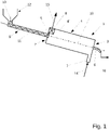
- the device has a ZKS 1 with a cylindrical housing 4, in which a front side 2 and an opposite rear side 3 are connected to one another via a substantially cylindrical housing jacket 4'.
- the ZKS 1 also has a separation material inlet 5 arranged essentially centrally on the end face 2 and a light material outlet 6 arranged essentially centrally on the rear side.
- the essentially cylindrical housing casing 4 ′ has an involute-shaped separating medium inlet 7 adjoining the rear side 3 of the ZKS and an involute-shaped separating medium outlet 8 adjoining the end face 2 of the ZKS 1 .
- the device shown also has a compulsory conveying device 9 connected to the inlet 5 for the material to be separated.
- the longitudinal axis 10 of the ZKS 1 is essentially aligned with the longitudinal axis 11 of the compulsory conveying device 9 aligned.
- the forced conveying device 9 is connected to a storage container 12 which has an agitator 13 .
- separating medium 14 is introduced into the separating medium inlet 7, preferably by a pump with a variable speed (not shown), so that a turbulent flow with an air core is generated along the longitudinal axis 10 of the ZKS 1 and that Separating medium exits the ZKS again through the separating medium outlet 8.
- Separating material is forcibly conveyed from the storage container 12 through the compulsory conveying device 9 into the separation material inlet 5 on the end face 2 of the ZKS 1 and is thus introduced essentially in the direction of the longitudinal axis 10 of the ZKS 1 .
- Low-density material floats at the interface between the separation medium and the air core and is conveyed along the longitudinal axis 10 of the ZKS 1 to the light material outlet 6 at the rear 3, where it emerges as a light material fraction 16.
- the longitudinal axis 10 of the ZKS 1 is preferably aligned at an angle of 20° to 40° to the horizontal, so that the transport of the low-density material from the separation material inlet 5 to the light material outlet 6 is ensured by gravity.
- material of higher density passes from the air core into the separation medium, is pushed radially outwards by the centrifugal force and leaves the ZKS 1 together with the separation medium through the separation medium outlet 8 as a heavy fraction 15.
- the direction of movement of the separation medium and the material to be separated are of lower density ie opposite in the embodiment shown.
- the separating medium flows in a turbulent path from the rear 3 of the ZKS 1 towards the front 2, while particles with low density move from the separation material inlet 5 on the front 2 to the light material outlet 6 on the rear 3 of the ZKS.
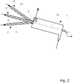
- the ZKS 1 essentially corresponds to the ZKS 1 in 1 embodiment shown.
- the in 2 The embodiment shown has three compulsory conveying devices 9, 9′, 9′′, which are connected to the separation material inlet 5 of the ZKS 1.
- the longitudinal axes 11, 11′, 11′′ of the forced conveying devices 9, 9', 9" are arranged at an angle to one another and to the longitudinal axis 10 of the ZKS.
- the forced conveying devices 9, 9', 9" can in turn be connected to storage containers (not shown), preferably having agitators or discharge trays.
- the method according to an exemplary embodiment of the invention may be substantially analogous to that referred to above in relation to FIG 1 described procedures are carried out.
- the material to be separated in the in 2 shown embodiment is introduced into the ZKS 1 via three separate compulsory conveying devices 9, 9', 9".
- different material to be separated e.g. in relation to the composition or the size distribution, can be introduced via the separate compulsory conveying devices 9, 9', 9".
- the compulsory conveying devices 9, 9′, 9′′ can be operated at different conveying speeds, which are adapted to the respective material to be separated.
Landscapes
- Centrifugal Separators (AREA)
- Combined Means For Separation Of Solids (AREA)
Priority Applications (10)
| Application Number | Priority Date | Filing Date | Title |
|---|---|---|---|
| EP21168568.0A EP4074420A1 (fr) | 2021-04-15 | 2021-04-15 | Séparation de la matière dans un séparateur à force centrifuge |
| US18/555,488 US20240198354A1 (en) | 2021-04-15 | 2022-04-14 | Separation of material to be separated in a centrifugal force separator |
| PL22723095.0T PL4323120T3 (pl) | 2021-04-15 | 2022-04-14 | Rozdzielanie materiału rozdzielanego w separatorze odśrodkowym |
| EP22723095.0A EP4323120B1 (fr) | 2021-04-15 | 2022-04-14 | Séparation de la matière dans un séparateur à force centrifuge |
| RS20250844A RS67149B1 (sr) | 2021-04-15 | 2022-04-14 | Odvajanje materijala za separaciju u centrifugalnom separatoru |
| ES22723095T ES3038248T3 (en) | 2021-04-15 | 2022-04-14 | Separation of separation material in a centrifugal separator |
| CA3215527A CA3215527A1 (fr) | 2021-04-15 | 2022-04-14 | Separation d'un produit a separer dans un separateur centrifuge |
| HUE22723095A HUE072400T2 (hu) | 2021-04-15 | 2022-04-14 | Elválasztandó anyag szétválasztása egy centrifugális erõvel mûködõ szeparátorban |
| PCT/EP2022/060085 WO2022219141A1 (fr) | 2021-04-15 | 2022-04-14 | Séparation d'un produit à séparer dans un séparateur centrifuge |
| HRP20250988TT HRP20250988T1 (hr) | 2021-04-15 | 2022-04-14 | Razdvajanje materijala za odvajanje u centrifugalnom separatoru |
Applications Claiming Priority (1)
| Application Number | Priority Date | Filing Date | Title |
|---|---|---|---|
| EP21168568.0A EP4074420A1 (fr) | 2021-04-15 | 2021-04-15 | Séparation de la matière dans un séparateur à force centrifuge |
Publications (1)
| Publication Number | Publication Date |
|---|---|
| EP4074420A1 true EP4074420A1 (fr) | 2022-10-19 |
Family
ID=75562533
Family Applications (2)
| Application Number | Title | Priority Date | Filing Date |
|---|---|---|---|
| EP21168568.0A Withdrawn EP4074420A1 (fr) | 2021-04-15 | 2021-04-15 | Séparation de la matière dans un séparateur à force centrifuge |
| EP22723095.0A Active EP4323120B1 (fr) | 2021-04-15 | 2022-04-14 | Séparation de la matière dans un séparateur à force centrifuge |
Family Applications After (1)
| Application Number | Title | Priority Date | Filing Date |
|---|---|---|---|
| EP22723095.0A Active EP4323120B1 (fr) | 2021-04-15 | 2022-04-14 | Séparation de la matière dans un séparateur à force centrifuge |
Country Status (9)
| Country | Link |
|---|---|
| US (1) | US20240198354A1 (fr) |
| EP (2) | EP4074420A1 (fr) |
| CA (1) | CA3215527A1 (fr) |
| ES (1) | ES3038248T3 (fr) |
| HR (1) | HRP20250988T1 (fr) |
| HU (1) | HUE072400T2 (fr) |
| PL (1) | PL4323120T3 (fr) |
| RS (1) | RS67149B1 (fr) |
| WO (1) | WO2022219141A1 (fr) |
Citations (7)
| Publication number | Priority date | Publication date | Assignee | Title |
|---|---|---|---|---|
| EP0876847A2 (fr) * | 1997-05-09 | 1998-11-11 | Baker Hughes (Deutschland) GmbH | Procédé pour séparer un mélange de matières plastiques |
| DE19847229A1 (de) | 1997-11-17 | 1999-05-20 | John Mcculloch | Verfahren und Vorrichtung zum Trennen von Mineralien |
| WO2002000352A1 (fr) | 2000-06-26 | 2002-01-03 | Ecomin Srl | Procede et dispositif d'alimentation pour separateurs dynamiques |
| JP2014230498A (ja) * | 2013-05-28 | 2014-12-11 | オリンパス株式会社 | 組織細片分離装置 |
| CN106861896A (zh) * | 2017-04-11 | 2017-06-20 | 钱兆鑫 | 叠加泵、增减压自身密度二产品旋流选煤装置 |
| CN109701732A (zh) * | 2019-01-14 | 2019-05-03 | 乌拉特中旗毅腾矿业有限责任公司 | 一种精煤清洁利用生产方法 |
| CN208928368U (zh) * | 2018-09-04 | 2019-06-04 | 安徽华星选矿科技有限公司 | 一种重介质旋流器的进料装置 |
Family Cites Families (13)
| Publication number | Priority date | Publication date | Assignee | Title |
|---|---|---|---|---|
| US2723750A (en) * | 1955-11-15 | Hydrocyclone | ||
| DE2645137C2 (de) * | 1976-10-06 | 1978-05-03 | Kraftwerk Union Ag, 4330 Muelheim | Einrichtung zur Gewinnung von Ölprodukten aus ölsanden |
| IT1086466B (it) * | 1977-09-06 | 1985-05-28 | Guarascio Massimo | Apparecchio separatore cilindrico per la separazione di miscele di solidi di differente perso specifico,particolarmente per l'industria mineraria |
| US4399027A (en) * | 1979-11-15 | 1983-08-16 | University Of Utah Research Foundation | Flotation apparatus and method for achieving flotation in a centrifugal field |
| GB8429933D0 (en) * | 1984-11-27 | 1985-01-03 | Coal Industry Patents Ltd | Cyclone separator means |
| FI111229B (fi) * | 2000-02-08 | 2003-06-30 | Fortum Oyj | Menetelmä ja laitteisto kiintoaineen erottamiseksi kaasuista |
| US7293657B1 (en) * | 2000-05-02 | 2007-11-13 | Krebs International | Hydrocyclone and method for liquid-solid separation and classification |
| US6540087B2 (en) * | 2001-01-25 | 2003-04-01 | Inter-Source Recovery Systems, Inc. | Part separator having multiple inlets and method of supplying wet chips through multiple inlets |
| NZ602606A (en) * | 2010-03-29 | 2014-04-30 | Newcastle Innovation Ltd | Enhanced gravity separation device using closely spaced channels |
| US20230078550A1 (en) * | 2020-02-10 | 2023-03-16 | Eastman Chemical Company | Centrifugal density separation of waste plastic |
| CA3186652A1 (fr) * | 2020-07-21 | 2022-01-27 | Gerard Melling | Appareil pour separer des composants d'une suspension |
| JP7767421B2 (ja) * | 2020-11-19 | 2025-11-11 | ライフ テクノロジーズ コーポレイション | 生体成分を分離するための遠心分離機及びスキッド並びに使用方法 |
| EP4696417A1 (fr) * | 2024-08-13 | 2026-02-18 | MANN+HUMMEL Ventures Pte. Ltd. | Agencement de séparateur centrifuge, système et procédé de collecte d'énergie dans un agencement de séparateur centrifuge |
-
2021
- 2021-04-15 EP EP21168568.0A patent/EP4074420A1/fr not_active Withdrawn
-
2022
- 2022-04-14 PL PL22723095.0T patent/PL4323120T3/pl unknown
- 2022-04-14 HR HRP20250988TT patent/HRP20250988T1/hr unknown
- 2022-04-14 HU HUE22723095A patent/HUE072400T2/hu unknown
- 2022-04-14 WO PCT/EP2022/060085 patent/WO2022219141A1/fr not_active Ceased
- 2022-04-14 CA CA3215527A patent/CA3215527A1/fr active Pending
- 2022-04-14 RS RS20250844A patent/RS67149B1/sr unknown
- 2022-04-14 EP EP22723095.0A patent/EP4323120B1/fr active Active
- 2022-04-14 ES ES22723095T patent/ES3038248T3/es active Active
- 2022-04-14 US US18/555,488 patent/US20240198354A1/en active Pending
Patent Citations (7)
| Publication number | Priority date | Publication date | Assignee | Title |
|---|---|---|---|---|
| EP0876847A2 (fr) * | 1997-05-09 | 1998-11-11 | Baker Hughes (Deutschland) GmbH | Procédé pour séparer un mélange de matières plastiques |
| DE19847229A1 (de) | 1997-11-17 | 1999-05-20 | John Mcculloch | Verfahren und Vorrichtung zum Trennen von Mineralien |
| WO2002000352A1 (fr) | 2000-06-26 | 2002-01-03 | Ecomin Srl | Procede et dispositif d'alimentation pour separateurs dynamiques |
| JP2014230498A (ja) * | 2013-05-28 | 2014-12-11 | オリンパス株式会社 | 組織細片分離装置 |
| CN106861896A (zh) * | 2017-04-11 | 2017-06-20 | 钱兆鑫 | 叠加泵、增减压自身密度二产品旋流选煤装置 |
| CN208928368U (zh) * | 2018-09-04 | 2019-06-04 | 安徽华星选矿科技有限公司 | 一种重介质旋流器的进料装置 |
| CN109701732A (zh) * | 2019-01-14 | 2019-05-03 | 乌拉特中旗毅腾矿业有限责任公司 | 一种精煤清洁利用生产方法 |
Also Published As
| Publication number | Publication date |
|---|---|
| EP4323120B1 (fr) | 2025-05-28 |
| CA3215527A1 (fr) | 2022-10-20 |
| HUE072400T2 (hu) | 2025-11-28 |
| EP4323120C0 (fr) | 2025-05-28 |
| HRP20250988T1 (hr) | 2025-10-24 |
| EP4323120A1 (fr) | 2024-02-21 |
| PL4323120T3 (pl) | 2025-09-29 |
| RS67149B1 (sr) | 2025-09-30 |
| US20240198354A1 (en) | 2024-06-20 |
| ES3038248T3 (en) | 2025-10-10 |
| WO2022219141A1 (fr) | 2022-10-20 |
Similar Documents
| Publication | Publication Date | Title |
|---|---|---|
| EP3274112B1 (fr) | Dispositif de refroidissement de sable de moulage | |
| AT243721B (de) | Vorrichtung zum Sortieren oder Klassieren fester, körniger Stoffe | |
| EP2465617B1 (fr) | Procédé et dispositif de séparation de fines particules à partir de produits en vrac en forme de granulés dans une conduite tubulaire | |
| DE3210972A1 (de) | Trennanlage | |
| DE2332948A1 (de) | Verfahren und vorrichtung zum mischen von feststoffen | |
| EP4168168A1 (fr) | Silo de mélange pour matériau en vrac, installation de production dotée d'un tel silo de mélange, et procédé de fonctionnement d'un tel silo de mélange | |
| EP0557816A2 (fr) | Procédé et installation pour séparer des matières plastiques broyées de composition chimique dissemblable et à densité différente | |
| DE102019000604A1 (de) | Verfahren und Vorrichtung zur flüssigkeitsarmen mechanischen Rohmaterialbeschickung von Durchlauftrennzentrifugen oder anderen Rotationsmaschinen und deren möglicher Entschickung über Siebmäntel oder einfachem Naßaustrag | |
| EP0555784A1 (fr) | Dispositif de triage des mélanges de solides | |
| DE2539960A1 (de) | Verfahren zur abtrennung und wiedergewinnung von kunststoffen aus kunststoffe enthaltenden abfaellen | |
| EP4323120B1 (fr) | Séparation de la matière dans un séparateur à force centrifuge | |
| EP0012461B1 (fr) | Installation de gazéification de charbon | |
| WO2024115253A1 (fr) | Appareil et procédé de séparation continue d'un mélange de matières plastiques | |
| DE1782428A1 (de) | Vollmantel-Schneckenzentrifuge | |
| DE19981222C1 (de) | Anlage und Verfahren zur Trennung von Stoffgemischen unterschiedlicher Dichte | |
| DE4329270A1 (de) | Anlage zur Trennung zerkleinerter Kunststoffe verschiedener chemischer Zusammensetzung und unterschiedlicher spezifischer Dichte und Verfahren zu seiner Durchführung | |
| DE1179881B (de) | Verfahren und Vorrichtung zum Sortieren von Mineralgemischen in einem Wasserzyklon | |
| EP0672455B1 (fr) | Dispositif de séparation par voie humide | |
| DE19750983B4 (de) | Anlage und Verfahren zur Trennung von Stoffgemischen unterschiedlicher Dichte | |
| DE19923600A1 (de) | Verfahren zur Aufbereitung von mineralischen Rohstoffen, insbesondere von Steinkohle | |
| DE3871992T2 (de) | Rotierende verarbeitungsmaschine fuer kunststoff- und polymermaterial mit ausgleich von betriebsschwankungen. | |
| DE19508050A1 (de) | Verfahren und Vorrichtung zur Trennung von Mischgütern insbesondere von körnigen und/oder plattenförmigen Kunststoffen bzw. Kunststoffolien | |
| DE1203734B (de) | Anlage zur Extraktion von loeslichen Stoffen aus festen pflanzlichen, tierischen oder anorganischen Stoffen im Gegenstrom | |
| DE899931C (de) | Verfahren und Vorrichtung zur Klassierung von Gemischen nach Fallgeschwindigkeit im aufsteigenden Fluessigkeitsstrom | |
| DE3716035C2 (fr) |
Legal Events
| Date | Code | Title | Description |
|---|---|---|---|
| PUAI | Public reference made under article 153(3) epc to a published international application that has entered the european phase |
Free format text: ORIGINAL CODE: 0009012 |
|
| STAA | Information on the status of an ep patent application or granted ep patent |
Free format text: STATUS: THE APPLICATION HAS BEEN PUBLISHED |
|
| AK | Designated contracting states |
Kind code of ref document: A1 Designated state(s): AL AT BE BG CH CY CZ DE DK EE ES FI FR GB GR HR HU IE IS IT LI LT LU LV MC MK MT NL NO PL PT RO RS SE SI SK SM TR |
|
| STAA | Information on the status of an ep patent application or granted ep patent |
Free format text: STATUS: THE APPLICATION IS DEEMED TO BE WITHDRAWN |
|
| 18D | Application deemed to be withdrawn |
Effective date: 20230420 |