EP4074445A2 - Foret étagé - Google Patents
Foret étagé Download PDFInfo
- Publication number
- EP4074445A2 EP4074445A2 EP22170818.3A EP22170818A EP4074445A2 EP 4074445 A2 EP4074445 A2 EP 4074445A2 EP 22170818 A EP22170818 A EP 22170818A EP 4074445 A2 EP4074445 A2 EP 4074445A2
- Authority
- EP
- European Patent Office
- Prior art keywords
- steps
- drill bit
- cutting edge
- degrees
- approximately
- Prior art date
- Legal status (The legal status is an assumption and is not a legal conclusion. Google has not performed a legal analysis and makes no representation as to the accuracy of the status listed.)
- Pending
Links
Images



Classifications
-
- B—PERFORMING OPERATIONS; TRANSPORTING
- B23—MACHINE TOOLS; METAL-WORKING NOT OTHERWISE PROVIDED FOR
- B23B—TURNING; BORING
- B23B51/00—Tools for drilling machines
- B23B51/009—Stepped drills
-
- B—PERFORMING OPERATIONS; TRANSPORTING
- B23—MACHINE TOOLS; METAL-WORKING NOT OTHERWISE PROVIDED FOR
- B23B—TURNING; BORING
- B23B51/00—Tools for drilling machines
- B23B51/02—Twist drills
-
- B—PERFORMING OPERATIONS; TRANSPORTING
- B23—MACHINE TOOLS; METAL-WORKING NOT OTHERWISE PROVIDED FOR
- B23B—TURNING; BORING
- B23B2251/00—Details of tools for drilling machines
- B23B2251/04—Angles, e.g. cutting angles
-
- B—PERFORMING OPERATIONS; TRANSPORTING
- B23—MACHINE TOOLS; METAL-WORKING NOT OTHERWISE PROVIDED FOR
- B23B—TURNING; BORING
- B23B2251/00—Details of tools for drilling machines
- B23B2251/04—Angles, e.g. cutting angles
- B23B2251/043—Helix angles
-
- B—PERFORMING OPERATIONS; TRANSPORTING
- B23—MACHINE TOOLS; METAL-WORKING NOT OTHERWISE PROVIDED FOR
- B23B—TURNING; BORING
- B23B2251/00—Details of tools for drilling machines
- B23B2251/04—Angles, e.g. cutting angles
- B23B2251/043—Helix angles
- B23B2251/046—Variable
-
- B—PERFORMING OPERATIONS; TRANSPORTING
- B23—MACHINE TOOLS; METAL-WORKING NOT OTHERWISE PROVIDED FOR
- B23B—TURNING; BORING
- B23B2251/00—Details of tools for drilling machines
- B23B2251/14—Configuration of the cutting part, i.e. the main cutting edges
-
- B—PERFORMING OPERATIONS; TRANSPORTING
- B23—MACHINE TOOLS; METAL-WORKING NOT OTHERWISE PROVIDED FOR
- B23B—TURNING; BORING
- B23B2251/00—Details of tools for drilling machines
- B23B2251/24—Overall form of drilling tools
- B23B2251/241—Cross sections of the diameter of the drill
- B23B2251/242—Cross sections of the diameter of the drill increasing in a direction towards the shank from the tool tip
Definitions
- the present invention relates to power tool accessories. More specifically, the present invention relates to step drill bits.
- Step drill bits are used in a variety of applications and industries where a user may need to drill holes through a thin-walled work piece.
- a step drill bit allows a user to drill holes in a progressive range of sizes with a single bit.
- Step drill bits can be coupled to a power tool such as a drill or an impact driver. In cases where a step drill bit is used with an impact driver, a cutting edge of the step drill edge is more prone to chipping.
- a first aspect of the invention provides a step drill bit comprising: a shank extending along a bit axis; a body having a proximal end adjacent the shank and a distal end opposite the proximal end, the body defining a plurality of axially stacked, progressively sized steps including a first step at the distal end, a terminal step at the proximal end, and a plurality of intermediate steps having incrementally increasing diameters disposed between the first and terminal steps; a flute in the body, the flute defining an elongated groove that extends from the distal end to the proximal end; and a plurality of cutting edges formed in the body, each cutting edge disposed along one of the plurality of steps, each cutting edge defining a helix angle and a rake angle; wherein the helix angle of the cutting edge at the terminal step is greater than the helix angle of the cutting edge at the first step; and wherein the rake angle of the cutting edge at the terminal step is greater than
- the plurality of intermediate steps may include at least four steps.
- a diameter of the terminal step may define a max diameter of the drill bit.
- the method may further comprise a transition portion between the body and the shank, the transition portion having a diameter that is smaller than the diameter of the terminal step.
- the flute may be a first flute, and the drill bit may further comprise a second flute on a diametrically opposite side of the bit axis from the first flute.
- the body may include a core depth defined between the first and second flutes and extending through the bit axis. The core depth may increase from the first step to the terminal step. Adjacent steps of the plurality of steps may be connected by a step chamfer.
- Each step chamfer may define a ramp angle between a surface of the step chamfer and a plane extending perpendicular to the bit axis. Each ramp angle may be between approximately 40 degrees and approximately 50 degrees.
- the body may include a bit tip adjacent the first step.
- the bit tip may include a primary tip angle measured through the bit axis between approximately 130 degrees and approximately 140 degrees.
- Each helix angle may be between approximately 5 degrees and approximately 30 degrees.
- Each rake angle may be between approximately 5 degrees and approximately 35 degrees.
- a second aspect of the present invention provides a step drill bit comprising: a shank extending along a bit axis; a body having a proximal end adjacent the shank and a distal end opposite the proximal end, the body defining a plurality of axially stacked, progressively sized steps including a first step at the distal end, a terminal step at the proximal end, and a plurality of intermediate steps having incrementally increasing diameters disposed between the first and terminal steps; a flute in the body extending from the distal end to the proximal end; and a plurality of cutting edges formed in the body, each cutting edge disposed along one of the plurality of steps, each cutting edge defining a helix angle and a rake angle; wherein the rake angle of the cutting edge at the terminal step is greater than the rake angle of the cutting edge at the first step.
- Each rake angle may be between approximately 5 degrees and approximately 35 degrees.
- the plurality of intermediate steps may include at least four steps.
- the rake angle of the cutting edge at the terminal step may increase by at least 40 percent relative to the rake angle of the cutting edge at the first step.
- a third aspect of the present invention provides a step drill bit comprising: a shank extending along a bit axis; a body having a proximal end adjacent the shank and a distal end opposite the proximal end, the body defining a plurality of axially stacked, progressively sized steps including a first step at the distal end, a terminal step at the proximal end, and a plurality of intermediate steps having incrementally increasing diameters disposed between the first and terminal steps; a flute in the body extending from the distal end to the proximal end; and a plurality of cutting edges formed in the body, each cutting edge disposed along one of the plurality of steps, each cutting edge defining a helix angle and a rake angle; wherein the helix angle of the cutting edge at the terminal step is greater than the helix angle of the cutting edge at the first step.
- Each helix angle may be between approximately 5 degrees and approximately 30 degrees.
- the plurality of intermediate steps may include at least four steps.
- the helix angle of the cutting edge at the terminal step may increase by at least 70 percent relative to the helix angle of the cutting edge at the first step.
- the invention provides a drill bit including a shank extending along a bit axis and a body with a proximal end adjacent the shank and a distal end opposite the proximal end.
- the body defines a plurality of axially stacked, progressively sized steps including a first step at the distal end and a terminal step at the proximal end.
- the drill bit also includes a flute in the body. The flute defines an elongated groove that extends from the distal end to the proximal end.
- the drill bit further includes a plurality of cutting edges formed in the body. Each cutting edge is disposed along one of the plurality of steps and defines a helix angle and a rake angle.
- the helix angle of the cutting edge at the terminal step is greater than the helix angle of the cutting edge at the first step.
- a ratio of the helix angle to the rake angle of the cutting edge at the first step is in a range from 0.5 to 2.4, and a ratio of the helix angle to the rake angle of the cutting edge at the terminal step is in a range of 0.9 to 1.7.
- the plurality of steps may include at least six steps.
- a diameter of the terminal step may define a max diameter of the drill bit.
- the drill bit may further comprise a transition portion between the body and the shank, the transition portion having a diameter that is smaller than the diameter of the terminal step.
- the flute may be a first flute, and the drill bit may further comprise a second flute on a diametrically opposite side of the bit axis from the first flute.
- the body may include a core depth defined between the first and second flutes and extending through the bit axis, the core depth increasing from the first step to the distal step.
- Adjacent steps of the plurality of steps may be connected by a step chamfer.
- Each step chamfer may define a ramp angle between a surface of the step chamfer and a plane extending perpendicular to the bit axis.
- Each ramp angle may be between approximately 40 degrees and approximately 50 degrees.
- the body may include a bit tip adjacent the first step.
- the bit tip may include a primary tip angle measured through the bit axis between approximately 130 degrees and approximately 140 degrees.
- Each helix angle may be between approximately 5 degrees and approximately 30 degrees.
- Each rake angle may be between approximately 5 degrees and approximately 35 degrees.
- the invention provides a drill bit including a shank extending along a bit axis and a body with a proximal end adjacent the shank and a distal end opposite the proximal end.
- the body defines a plurality of axially stacked, progressively sized steps including a first step at the distal end and a terminal step at the proximal end.
- the drill bit also includes a flute in the body. The flute defines an elongated groove that extends from the distal end to the proximal end.
- the drill bit further includes a plurality of cutting edges formed in the body. Each cutting edge is disposed along one of the plurality of steps and defines a helix angle and a rake angle.
- the helix angle of the cutting edge at the terminal step is greater than the helix angle of the cutting edge at the first step.
- the rake angle of the cutting edge at the terminal step is greater than the rake angle of the cutting edge at the first step.
- the plurality of steps may include at least six steps.
- Each helix angle may be between approximately 5 degrees and approximately 30 degrees.
- Each rake angle may between approximately 5 degrees and approximately 35 degrees.
- the invention provides a drill bit including a shank extending along a bit axis and a body with a proximal end adjacent the shank and a distal end opposite the proximal end.
- the body defines a plurality of axially stacked, progressively sized steps including a first step at the distal end and a terminal step at the proximal end.
- the drill bit also includes at least one flute in the body. Each flute defines an elongated groove that extends from the distal end to the proximal end.
- the drill bit further includes a plurality of cutting edges formed in the body. Each cutting edge is disposed along one of the plurality of steps and defines a helix angle and a rake angle.
- the helix angle of the cutting edge at the terminal step increases by at least 70 percent relative to the helix angle of the cutting edge at the first step.
- the rake angle of the cutting edge at the terminal step increases by at least 40 percent relative to the rake angle of the cutting edge at the first step.
- the helix angle may increase from the first step to the terminal step within a range between 70 and 450 percent.
- the rake angle may increase from the first step to the terminal step within a range between 40 and 500 percent
- the plurality of steps may include at least six steps.
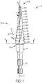
- FIGS. 1-7 illustrate a step drill bit 10 for use with a power tool, such as, for example, a drill, a driver drill, an impact driver, and the like.
- the step drill bit 10 may be used to cut holes or drill into a workpiece such as sheet metal, wood, and the like.
- the illustrated step drill bit 10 comes in a variety of sizes that correspond to the type of hole to be drilled.
- FIGS. 1 and 2 illustrate a step drill bit 10 including a shank 12, a transition portion 16, and a body 18.
- the shank 12 is configured to engage a power tool for rotation of the step drill bit 10 about a bit axis 14.
- the illustrated bit axis 14 is a central longitudinal axis of the step drill bit 10.
- the transition portion 16 is defined between the shank 12 and the body 18.
- the body 18 includes a first or proximate end 19A adjacent the shank 12 and a second or distal end 19B opposite the proximate end 19A.
- the body 18 defines axially stacked, progressively sized steps 20A-20M between a bit tip 21 and the transition portion 16.
- the steps 20A-20M are axially stacked in that the steps 20A-20M are coaxially arranged along the bit axis 14.
- the steps 20A-20M are progressively sized in that the steps 20A-20M incrementally increase in size (e.g., diameter) from the bit tip 21, or the distal end 19B, of the body 18 to the transition portion 16, or proximate end 19A.
- the body 18 includes thirteen steps 20A-20M. In other embodiments, the body 18 may include fewer or more steps.
- the shank 12 may be a hex-shaped shaft, a round shaped shank, a 3-flat type shank, or any other shank 12 that is configured to be coupled to a power tool.
- the shank 12 has a diameter between of approximately 0.125 inches to 0.3 inches.
- an indication band may be located on the shank 12.
- the indication band may indicate to a user the type of the step drill bit 10.
- the step drill bit 10 may include laser engravings that indicate to a user the size or type of step drill bit.
- the indication band may be a variety of colors such as red, green, blue, purple, orange, yellow, etc.
- each of the steps 20A-20M of the body 18 has a step height 56A-56M.
- the step heights 56A-56M are not required to be the same for all steps.
- steps that correspond to commonly-used drill diameters e.g., 0.5 inch, 0.75 inch, etc.
- steps that correspond to commonly-used drill diameters may have larger heights to allow a user to more easily control the step drill bit 10 to stop at those corresponding steps.
- the illustrated steps include a first step 20A at the distal end 19B of the body 18 and a terminal step 20M coupled to the transition portion 16.
- the first step 20A has a diameter of approximately 0.125 inches
- the terminal step 20M has a diameter of approximately 0.505 inches.
- the diameter of the terminal step 20M defines a max diameter of the step drill bit 10.
- the diameter of the terminal step 20M is greater than a diameter of the transition portion 16.
- the intermediate steps 20B-20L located between the first and terminal steps 20A, 20M have incrementally increasing diameters within the range of 0.125 inches and 0.505 inches.
- the body 18 may include fewer or more steps, and/or each step 20A-20M may have a different diameter.
- a step chamfer 58 is formed between each pair of adjacent steps 20A-20M.
- the step chamfer 58 connects two adjacent steps at a ramp angle 60 to provide a smoother transition between the adjacent steps.
- the ramp angle 60 is measured between a surface of the corresponding step chamfer 58 and a plane 61 extending perpendicular to the bit axis 14.
- the ramp angle 60 for all of the step chamfers 58 is between approximately 40 degrees and approximately 50 degrees, and more specifically, approximately 45 degrees.
- the ramp angle 60 may be relatively larger or smaller, or the step chamfers 58 may be omitted.
- the ramp angle 60 is the same for all the steps 20. In other embodiments, the ramp angle 60 may vary per step 20
- the bit tip 21 has a primary tip angle 22 measured through the bit axis 14. In some embodiments, the tip angle 22 is between approximately 130 degrees and approximately 140 degrees. In the illustrated embodiment, the tip angle 22 is approximately 135 degrees. As shown in FIG. 5 , the bit tip 21 includes a dual-relief tip having two first chisel surfaces 24 and two second chisel surfaces 26. Each first chisel surface 24 is located on an opposite side of a chisel edge 28 of the bit tip 21 from a corresponding second chisel surface 26. The bit tip 21 defines a chisel width 30 measured between cutting edges 32 of the chisel surfaces 24, 26.
- the chisel width 30 is between approximately 0.02 inches and 0.03 inches. In other embodiments, the chisel width 30 is between approximately 0.022 inches and approximately 0.028 inches. In the illustrated embodiment, the chisel width 30 is approximately 0.025 inches. In further embodiments, the primary tip angle 22 and/or the chisel width 30 may be relatively larger or smaller.
- the body 18 defines two body flutes 46 disposed on diametrically opposite sides of the bit axis 14. Each of the flutes 46 is helically wrapped around the body 18 and extends from the first step 20A to the transition portion 16. Each flute 46 defines a groove 48 between two edges 50A-B in the body 18.
- the step drill bit 10 includes two flutes 46. In other embodiments, the step drill bit 10 may include a single flute 46 or more than two flutes 46.
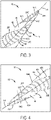
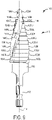
- each of the steps 20A-20M includes a leading cutting edge (e.g., cutting edges 64A labeled in FIG. 3 , cutting edge 64C labeled in FIGS. 3 and 4 , and cutting edge 64M labeled in FIG. 6 ).
- the leading cutting edges are defined on the edge 50A of the groove 48 of the flute 46.
- Each cutting edge forms a rake angle between the outer periphery of a respective step 20A-20M and the surface of the groove 48 (e.g., rake angle 66C labeled in FIG. 4 and rake angle 66M labeled in FIG. 6 ).
- the rake angle at the first step 20A is approximately 5 degrees and the rake angle at the terminal step 20M is approximately 25 degrees.
- the intermediate steps 20B-20L have incrementally increasing rake angles that are within a range from 5 degrees and 25 degrees. In some embodiments, the increase to the rake angles may be linear or non-linear. In other embodiments, the rake angles may be smaller than 5 degrees or bigger than 25 degrees.
- each cutting edge defines a helix angle that is measured between the cutting edge 64A-64M and the bit axis 14 (e.g., helix 68C labeled in FIG. 3 ).
- the helix angle at the first step 20A is approximately 12 degrees and the helix angle at the terminal step 20M is approximately 22 degrees.
- the intermediate steps 20B-20L have incrementally increasing helix angles that are within a range from 12 degrees to 22 degrees. In some embodiments, the increase to the helix angles may be linear or non-linear. In other embodiments, the helix angles may be smaller than 12 degrees or larger than 22 degrees.
- a ratio between the helix angle and the rake angle for the first step 20A is approximately 2.4, and the ratio between the helix angle and the rake angle for the terminal step 20M is approximately 0.9.
- a core depth 52 of the step drill bit 10 is defined between the two flutes 46 of the body 18 extending through the bit axis 14.
- the core depth 52 increases from the distal end 19B of the body 18 to the proximal end 19B of the body. As such, the core depth 52 increases every step 20A-20M from the first step 20A to the terminal step 20M.
- the core depth 52 may be in a range from 0.05 inches to 0.6 inches.
- the thirteen steps 20A-20M of the step drill bit 10 each include three types of reliefs: an axial relief 74 ( FIG. 7 ), a diametral relief 76 ( FIG. 7 ), and a radial relief 78 ( FIG. 5 ).
- the axial relief 74 of each step 20A-20M is the amount by which an upper edge 80 of the step (i.e., the edge of the step closest to the distal end of the body 18) translates along the bit axis 14 toward the distal end as the upper edge 80 nears a leading cutting edge 64C of the step (i.e., the edge of the step at the body flute 46).
- the axial relief 74 of each step 20A-20M is between approximately 0.002 inches and approximately 0.01 inches. In the illustrated embodiment, the axial relief 74 is approximately 0.005 inches. In other embodiments, the axial relief 74 may be relatively larger or smaller.
- the diametral relief 76 of each step 20A-20M is the amount by which an outer circumferential surface 84 of the step tapers radially inward or outward along the bit axis 14.
- the diametral relief 76 of each step 20A-20M is between approximately -1 degree and approximately 1 degree.
- the diametral relief 76 may be omitted (i.e., may be 0 degrees).
- the diametral relief 76 may be a relatively greater positive degree or a relatively greater negative degree.
- the radial relief 78 is the amount by which a radius 86 of the steps 20A-20M decreases as the outer surface of the step 20A-20M moves away from the leading edge 82. More particularly, a constant diameter circle 88 is illustrated in FIG. 5 in broken lines, representing the nominal diameter of the third step 201.
- the radial relief 78 continuously increases along a radial relief angle 34 from the leading edge 82 of the step to a point at which the radial relief 78 has reached its maximum value or amount.
- the "radial relief' is the maximum amount that the radius 86 of the step 201 decreases radially inward from the nominal diameter 88.
- the radial relief 78 of each step 20A-20M is between approximately 0.002 inches and approximately 0.01 inches. In the illustrated embodiment, the radial relief 78 is approximately 0.005 inches. In addition, the radial relief angle 34 of each step 20A-20M is between approximately 40 degrees and approximately 50 degrees from the leading edge 82. In the illustrated embodiment, the radial relief angle 34 is approximately 45 degrees. In other embodiments, the radial relief 78 and/or the radial relief angle 34 may be relatively larger or smaller.
- FIGS. 8-9 illustrate a step drill bit 110 according to another embodiment of the invention.
- the step drill bit 110 includes features similar to the step drill bit 10 of FIGS. 1-7 , and like features have been given like reference numbers plus 100.
- the step drill bit 110 may include any combination of features, dimensions, or range of dimensions from the preceding or subsequent embodiments, but only features of the step drill bit 110 not yet discussed with respect to the previous embodiment are detailed below.
- the step drill bit 110 includes two flutes 146 and twelve axially stacked, progressively sized steps 120A-120L.
- a first step 120A has a diameter of approximately 0.188 inches
- a terminal step 120L has a diameter of approximately 0.88 inches.
- Each of the steps 120A-120L include a leading cutting edge 164A-164L.
- Each cutting edge 164A-164L forms a rake angle (e.g., rake angle 166G labeled in FIG. 9 ) between the outer periphery of a respective step 120A-120L and the surface of a flute 146 and a helix angle (e.g., helix angle 1681 labeled in FIG. 8 ) that is measured between the cutting edge 164A-164L and a bit axis 114.
- the rake angle at the first step 120A is approximately 5 degrees
- the rake angle at the terminal step 20L is approximately 18 degrees.
- the intermediate steps 120B-120K have incrementally increasing rake angles that are within a range from 5 degrees and 18 degrees.
- the increase to the rake angles may be linear or non-linear.
- the rake angles may be smaller than 5 degrees or bigger than 18 degrees.
- the helix angle at the first step 120A is approximately 7 degrees
- the helix angle at the terminal step 120L is approximately 29 degrees
- the intermediate steps 120B-220K have incrementally increasing helix angles that are within a range from 7 degrees to 29 degrees.
- the increase to the helix angles may be linear or non-linear.
- the helix angles may be smaller than 7 degrees or larger than 29 degrees.
- a ratio between the helix angle and the rake angle for the first step 120A is approximately 1.4
- the ratio between the helix angle and the rake angle for the terminal step 120L is approximately 1.6.
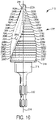
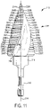
- FIGS. 10-11 illustrate a step drill bit 210 according to another embodiment of the invention.
- the step drill bit 210 includes features similar to the step drill bit 10 of FIGS. 1-7 , and like features have been given like reference numbers plus 100.
- the step drill bit 210 may include any combination of features, dimensions, or range of dimensions from the preceding or subsequent embodiments, but only features of the step drill bit 210 not yet discussed with respect to the previous embodiment are detailed below.
- the step drill bit 210 includes two flutes 246 and twenty axially stacked, progressively sized steps 220A-220T.
- a first step 220A has a diameter of approximately 0.188 inches
- a terminal step 220T has a diameter of approximately 1.13 inches.
- Each of the steps 220A-220T includes a leading cutting edge 264A-264T.
- Each cutting edge 264A-264T forms a rake angle (e.g., rake angle 266L labeled in FIG. 10 ) between the outer periphery of a respective step 220A-220T and the surface of a flute 246 and a helix angle (e.g., helix angle 268L labeled in FIG. 11 ) that is measured between the cutting edge 264A-264T and a bit axis 214.
- the rake angle at the first step 220A is approximately 20 degrees
- the rake angle at the terminal step 20L is approximately 12 degrees
- the intermediate steps 220B-220S have incrementally decreasing rake angles that are within a range from 12 degrees and 20 degrees.
- the decrease to the rake angles may be linear or non-linear.
- the rake angles may be smaller than 12 degrees or bigger than 20 degrees.
- the helix angle at the first step 220A is approximately 10 degrees
- the helix angle at the terminal step 220T is approximately 18 degrees.
- the intermediate steps 220B-220S have incrementally increasing helix angles that are within a range from 10 degrees to 18 degrees. In some embodiments, the increase to the helix angles may be linear or non-linear. In other embodiments, the helix angles may be smaller than 10 degrees or larger than 18 degrees. In the illustrated embodiment, a ratio between the helix angle and the rake angle for the first step 220A is approximately 0.5, and the ratio between the helix angle and the rake angle for the terminal step 220T is approximately 1.5.
- the step drill bit 10, 110, 210 may include any number of steps 20, 120, 220 with any range of diameters that incrementally increase from the first step 20 to the terminal step 20. As shown in Table 1 below, for a particular minimum diameter to maximum diameter and number of steps of a step drill bit 10, 110, 210 the ratio between the first step 20 and the terminal step 20 may vary depending on the type of step drill bit 10, 110, 210. Helix Angle/Rake Angle Min. Diameter (in) Max.
- the percent the rake angle and the helix angle change from the first step 20 and the terminal step 20 may vary depending on the type of step drill bit 10, 110, 120.
- Table 2 below shows the percent of change between the first step 20 and the terminal step 20.
- the helix angle of the cutting edge at the terminal step of a drill bit 10, 110, 210 may increase by at least 70 percent relative to the helix angle of the cutting edge at the first step of the drill bit 10, 110, 210.
- the rake angle of the cutting edge at the terminal step of the drill bit 10, 110, 210 may increase by at least 40 percent relative to the rake angle of the cutting edge at the first step of the drill bit 10, 110, 210.
- the helix angle increases from the first step to the terminal step within a range between 70 and 450 percent
- the rake angle increases from the first step to the terminal step within a range between 40 and 500 percent.
- the percent change may be positive indicating the rake angle or helix angle increased from the first step 20 to the terminal step 20. In other embodiments, the percent change may be negative indicating the rake angle or helix angle decreased from the first step 20 to the terminal step 20. Helix Angle Rake Angle Max.
- the step drill bit 10, 110, 210 may include laser etchings on an outside surface of the steps 20 indicating to a user the diameter of a hole the particular step 20 would drill in a workpiece.
- the step drill bit 10,110, 210 may be coated in a protective coating with properties that increase wear resistance.
- the step drill bit 10, 110, 210 may be coated in a titanium aluminum nitride coating (i.e., TiAIN) that is 2-5 microns thick.
- the step drill bit 10, 110, 210 may be coated in a titanium nitride coating (i.e., TiN) that is 2-5 microns thick.
- step drill bit 10,110, 210 may be coated in an aluminum titanium nitride (i.e., AlTiN).
- step drill bits 10, 110, 210 with TiAIN, TiN, or AlTiN coatings may be heat treated and tempered. In other embodiments, the step drill bit may only be heat treated and tempered.
- Optimizing the ratio between a helix angle and a rake angle on the cutting edges of steps on a step drill bit advantageously increases the speed and life of the step drill bit.
- a helix angle that is too high at a distal end of the step drill bit will provide poor hole quality.
- a helix angle that is too low at a distal end will cause the step drill bit to be slower during operation.
- a helix angle that is too high at the proximate end of a step drill bit will jam during operation.
- a helix angle that is too low at the proximate end of a step drill bit will be slower during operation and lessen the life of the step drill bit.
- a rake angle that is too high at the front and back of the step drill bit will cause the cutting edge to chip.
- a rake angle that is too low at the front and back of the step drill bit will be slow and produce poor hole quality.
- providing a step drill bit with a ratio between the helix angle and the rake angle between 0.5 and 2.4 ensures that the step drill bit cuts workpieces in a fast and clean manner while prolonging the life. Additionally, adding a wear resistance coating to the step drill bit will prolong the life of the step drill bit further.
Landscapes
- Engineering & Computer Science (AREA)
- Mechanical Engineering (AREA)
- Drilling Tools (AREA)
Applications Claiming Priority (2)
| Application Number | Priority Date | Filing Date | Title |
|---|---|---|---|
| US201862662857P | 2018-04-26 | 2018-04-26 | |
| EP19171221.5A EP3560643B1 (fr) | 2018-04-26 | 2019-04-25 | Foret étagé |
Related Parent Applications (2)
| Application Number | Title | Priority Date | Filing Date |
|---|---|---|---|
| EP19171221.5A Division-Into EP3560643B1 (fr) | 2018-04-26 | 2019-04-25 | Foret étagé |
| EP19171221.5A Division EP3560643B1 (fr) | 2018-04-26 | 2019-04-25 | Foret étagé |
Publications (2)
| Publication Number | Publication Date |
|---|---|
| EP4074445A2 true EP4074445A2 (fr) | 2022-10-19 |
| EP4074445A3 EP4074445A3 (fr) | 2023-03-01 |
Family
ID=66323688
Family Applications (2)
| Application Number | Title | Priority Date | Filing Date |
|---|---|---|---|
| EP22170818.3A Pending EP4074445A3 (fr) | 2018-04-26 | 2019-04-25 | Foret étagé |
| EP19171221.5A Active EP3560643B1 (fr) | 2018-04-26 | 2019-04-25 | Foret étagé |
Family Applications After (1)
| Application Number | Title | Priority Date | Filing Date |
|---|---|---|---|
| EP19171221.5A Active EP3560643B1 (fr) | 2018-04-26 | 2019-04-25 | Foret étagé |
Country Status (3)
| Country | Link |
|---|---|
| US (3) | US11273501B2 (fr) |
| EP (2) | EP4074445A3 (fr) |
| CN (1) | CN211464929U (fr) |
Cited By (1)
| Publication number | Priority date | Publication date | Assignee | Title |
|---|---|---|---|---|
| EP4527528A1 (fr) * | 2023-09-22 | 2025-03-26 | Shajeng Hardware Co., Ltd. | Foret étagé |
Families Citing this family (16)
| Publication number | Priority date | Publication date | Assignee | Title |
|---|---|---|---|---|
| US11007583B2 (en) | 2016-02-14 | 2021-05-18 | Hongjia Wang | Twist drill |
| USD882794S1 (en) * | 2018-01-31 | 2020-04-28 | Beijing Smtp Technology Co., Ltd. | Ultrasonic cutter head |
| USD980979S1 (en) * | 2018-11-30 | 2023-03-14 | Shukla Medical | Nail extractor |
| WO2020165378A1 (fr) * | 2019-02-15 | 2020-08-20 | Colt Technologies Gmbh | Foret comprenant une pointe de centrage |
| CN110802259B (zh) * | 2019-11-28 | 2021-07-06 | 上海钰工机电有限公司 | 麻花钻 |
| EP4185431A4 (fr) * | 2020-07-23 | 2024-11-06 | Milwaukee Electric Tool Corporation | Foret étagé |
| US20220371105A1 (en) * | 2021-05-19 | 2022-11-24 | Black & Decker Inc. | Step drill bits |
| USD1050206S1 (en) * | 2022-01-12 | 2024-11-05 | Zonghong Li | Drill bit with sleeve |
| US20230347422A1 (en) * | 2022-04-28 | 2023-11-02 | Milwaukee Electric Tool Corporation | Accessory tools |
| USD1033191S1 (en) * | 2022-08-10 | 2024-07-02 | Black & Decker Inc. | Step drill bit |
| US20240051040A1 (en) * | 2022-08-10 | 2024-02-15 | Black & Decker Inc. | Step drill bit |
| CN117655377A (zh) * | 2022-08-24 | 2024-03-08 | 上海钰工工具有限公司 | 阶梯钻和利用阶梯钻对工件进行钻孔切削的方法 |
| AU2022475626A1 (en) | 2022-08-24 | 2025-03-20 | Tec-Spiral Enterprises Tools Co., Ltd | Step drill and method for drilling a workpiece by using a step drill |
| DE102022211783A1 (de) * | 2022-11-08 | 2024-05-08 | Robert Bosch Gesellschaft mit beschränkter Haftung | Metallbohrer |
| USD1061646S1 (en) * | 2023-04-26 | 2025-02-11 | Hongdan Qu | Drill bit |
| USD1069871S1 (en) * | 2023-09-01 | 2025-04-08 | Shajeng Hardware Co., Ltd. | Step drill |
Citations (1)
| Publication number | Priority date | Publication date | Assignee | Title |
|---|---|---|---|---|
| DE19526686B4 (de) * | 1994-09-09 | 2010-11-04 | Dürr Präzisionswerkzeuge GmbH | Mehrstufenbohrer |
Family Cites Families (143)
| Publication number | Priority date | Publication date | Assignee | Title |
|---|---|---|---|---|
| US213937A (en) | 1879-04-01 | Improvement in reamers | ||
| US347864A (en) | 1886-08-24 | Screw tap | ||
| US499098A (en) | 1893-06-06 | Pipe-burr-removing implement | ||
| DE246060C (fr) | ||||
| US550190A (en) | 1895-11-19 | Reamer-bit | ||
| US716557A (en) | 1902-09-03 | 1902-12-23 | Seward R Seybold | Tubular auger. |
| US938484A (en) | 1908-03-09 | 1909-11-02 | Pratt & Whitney Co | Taper-roughing tool. |
| GB155004A (en) * | 1919-09-06 | 1920-12-06 | Thomas Robertson | An improved spirally fluted drill |
| US1620536A (en) | 1926-03-29 | 1927-03-08 | Gairing Tool Company | Interchangeable boring and counterboring tool |
| US2193186A (en) | 1938-06-06 | 1940-03-12 | Herbert G Hard | Twist drill |
| US2276532A (en) | 1940-05-29 | 1942-03-17 | Bethlehem Steel Corp | Drill |
| GB540073A (en) | 1940-07-22 | 1941-10-03 | Ferranti Ltd | Improvements in or relating to metal drills |
| US2389909A (en) | 1944-01-17 | 1945-11-27 | Hofbauer Frank | Rotary cutting tool |
| US2555746A (en) | 1945-12-28 | 1951-06-05 | Horsky Milo | Drill |
| US2607562A (en) | 1951-03-19 | 1952-08-19 | Phipps Orville | Self-piloted rotary drill bit |
| US2786373A (en) | 1953-12-14 | 1957-03-26 | Patton William Kenneth | Straight flute drilling cutter |
| DE1041324B (de) | 1954-12-21 | 1958-10-16 | Rohde & Doerrenberg | Stufenbohrer oder -senker |
| US2855181A (en) | 1955-12-19 | 1958-10-07 | Ole K Olsen | Drill bits |
| US2897696A (en) | 1956-01-13 | 1959-08-04 | Henry R Tisserant | Sheet metal panel drill |
| DE1063878B (de) | 1958-07-11 | 1959-08-20 | Schuette Fa Alfred H | In axialer Richtung hinterschnittener, in einem Halter eingeklemmter Schaftformstahl |
| US3076356A (en) | 1960-09-19 | 1963-02-05 | Simich Emil | Cutting tool |
| GB1202086A (en) | 1967-10-10 | 1970-08-12 | Barworth Flockton Ltd | Improved drill |
| FR2029963A5 (fr) | 1969-03-19 | 1970-10-23 | Petroles Cie Francaise | |
| US3645640A (en) | 1970-06-11 | 1972-02-29 | Michael F Zukas | Rotary cutter tool |
| FR2135053B1 (fr) | 1971-05-04 | 1974-08-19 | Petroles Cie Francaise | |
| US3758222A (en) | 1971-12-30 | 1973-09-11 | H Oakes | Drill bit |
| US3836278A (en) | 1972-12-14 | 1974-09-17 | Int Research & Dev Co Ltd | Tapered drill bit |
| US4032251A (en) | 1975-05-05 | 1977-06-28 | The Weldon Tool Company | Countersinking and deburring tool |
| US4189266A (en) | 1975-08-01 | 1980-02-19 | George Koslow | Rotary drill bit for hand-held power drills |
| US4073354A (en) | 1976-11-26 | 1978-02-14 | Christensen, Inc. | Earth-boring drill bits |
| SE417680B (sv) | 1977-02-04 | 1981-04-06 | Vnii Mekhanizirovannogo I Ruch | Roterbart verktyg for upptagande av hal |
| FR2385883A1 (fr) | 1977-03-31 | 1978-10-27 | Petroles Cie Francaise | Outil de forage a haut rendement a attaque rapide de la carotte |
| US4098363A (en) | 1977-04-25 | 1978-07-04 | Christensen, Inc. | Diamond drilling bit for soft and medium hard formations |
| US4127355A (en) | 1977-09-06 | 1978-11-28 | Oakes Harry C | Wood bit |
| US4244432A (en) | 1978-06-08 | 1981-01-13 | Christensen, Inc. | Earth-boring drill bits |
| US4351401A (en) | 1978-06-08 | 1982-09-28 | Christensen, Inc. | Earth-boring drill bits |
| DE2921190C2 (de) | 1979-05-25 | 1985-05-09 | Rothenberger GmbH & Co Werkzeuge-Maschinen KG, 6000 Frankfurt | Blechschälbohrer, insbesondere zum Herstellen von Öffnungen in Karosserieteilen zur Hohlraumkonservierung |
| US4662803A (en) | 1979-10-18 | 1987-05-05 | Rockwell International Corporation | Reamer with unequally spaced flutes |
| US4360069A (en) | 1980-07-21 | 1982-11-23 | Kenneth Davis | Diamond drill bits |
| SE426148B (sv) | 1981-10-12 | 1982-12-13 | Hugo Linden | Byggbart borr |
| US4582458A (en) | 1984-08-09 | 1986-04-15 | American Saw & Mfg. Company | Stepped drill construction |
| JPS6316912A (ja) | 1986-07-10 | 1988-01-23 | Gotou Matsue | 多段ドリル |
| US5288183A (en) | 1986-08-18 | 1994-02-22 | Black & Decker Inc. | Self-centering drill bit with pilot tip |
| US4815902A (en) | 1987-07-01 | 1989-03-28 | Petersen Manufacturing Co., Inc. | Stepped fluted drill |
| DE3805727A1 (de) | 1988-02-24 | 1989-08-31 | Krauss Fa H Willy | Bohr- oder reibwerkzeug |
| FR2668087A1 (fr) | 1990-10-22 | 1992-04-24 | Aerospatiale | Outil et dispositif de percage a evacuation de copeaux perfectionnee. |
| US5273380A (en) | 1992-07-31 | 1993-12-28 | Musacchia James E | Drill bit point |
| DE9403827U1 (de) | 1993-05-14 | 1994-11-03 | Geberit Technik Ag, Jona | Werkzeug zum Kalibrieren und Entgraten von Rohrenden |
| US5326196A (en) | 1993-06-21 | 1994-07-05 | Noll Robert R | Pilot drill bit |
| JP2792017B2 (ja) | 1993-12-06 | 1998-08-27 | 日本軽金属株式会社 | 複合パネルの穿孔方法 |
| US5452971A (en) | 1994-03-08 | 1995-09-26 | Nevills; Alva D. | Rotary end cutting tool |
| US5466100A (en) | 1994-10-24 | 1995-11-14 | Alfa Manufacturing Industries, Inc. | Multi-stepped power drill bit having handle chuck adaptor |
| US5622462A (en) | 1995-04-11 | 1997-04-22 | Credo Tool Company | Twist drill bit |
| JP2922448B2 (ja) | 1995-10-06 | 1999-07-26 | 株式会社ミヤナガ | 多段ビット |
| JP3165636B2 (ja) | 1996-01-31 | 2001-05-14 | キヤノン株式会社 | 画像形成装置 |
| DE29603475U1 (de) | 1996-02-27 | 1996-04-18 | Giess & Quanz GmbH, 42859 Remscheid | Bohrwerkzeug |
| JPH09285907A (ja) | 1996-04-22 | 1997-11-04 | Nissho Koki Kk | 多段式ドリル及び電気ドリル |
| JP2922847B2 (ja) | 1996-06-05 | 1999-07-26 | 株式会社ミヤナガ | 多段ビット用ストッパー |
| GB2318072A (en) | 1996-09-21 | 1998-04-15 | Plansee Tizit Gmbh | Masonry bit |
| US5807039A (en) | 1997-02-13 | 1998-09-15 | Credo Tool Company | Drill bit |
| ES2201412T3 (es) | 1997-05-29 | 2004-03-16 | Black & Decker Inc. | Broca helicoidal. |
| DE19806864A1 (de) | 1998-02-19 | 1999-08-26 | Beck August Gmbh Co | Reibwerkzeug und Verfahren zu dessen Herstellung |
| JP4014720B2 (ja) | 1998-02-23 | 2007-11-28 | 大見工業株式会社 | ステップドリル |
| DE19903276A1 (de) | 1999-01-28 | 2000-08-10 | Maier Kg Andreas | Spanabhebendes Werkzeug und Verfahren zu seiner Herstellung |
| DE29904042U1 (de) | 1999-03-05 | 1999-07-29 | Dähn & Klein GmbH, 67823 Obermoschel | Stufenbohrer |
| WO2001010587A1 (fr) | 1999-08-11 | 2001-02-15 | Andre Jurgens | Trepans |
| USD449627S1 (en) | 1999-10-01 | 2001-10-23 | Kabushiki Kaisha Shinei Selsakusho | Cutter |
| JP3269812B2 (ja) * | 1999-10-01 | 2002-04-02 | 秋雄 武和 | 段付き回転切削工具 |
| DE19950390A1 (de) | 1999-10-11 | 2001-04-12 | Adam Krecisz | Bohrer zur Herstellung von Löcher mit begrenzter Tiefe |
| US6428250B2 (en) | 2000-02-02 | 2002-08-06 | Karl-Heinz Giebmanns | Drill bit for wood drilling |
| DE20015550U1 (de) | 2000-09-08 | 2000-10-26 | Quanz, Reiner, 42859 Remscheid | Stufenbohrer |
| WO2002055231A2 (fr) | 2001-01-12 | 2002-07-18 | Asar Group | Ensemble rivet auto-polissable et auto-taraudeur |
| EP1340573B1 (fr) | 2002-02-28 | 2006-07-12 | Robert Bosch Gmbh | Procédé de fabrication pour un foret ou une fraise |
| KR20030084082A (ko) | 2002-04-24 | 2003-11-01 | 고성림 | 버형성을 최소화하기 위한 스텝 드릴 |
| DE20212852U1 (de) | 2002-08-16 | 2002-12-12 | RUKO GmbH Präzisionswerkzeuge, 71088 Holzgerlingen | Mehrstufen-Bohrwerkzeug |
| US6890133B2 (en) | 2002-10-18 | 2005-05-10 | Irwin Industrial Tool Company | Stepped drill bit having split tip |
| AU2003289784A1 (en) | 2003-01-02 | 2004-07-29 | Ross M. Colquhoun | Cutting tool with depth of cut markings |
| DE20303656U1 (de) | 2003-03-06 | 2003-05-08 | Quanz, Reiner, 42859 Remscheid | Stufenbohrer |
| DE20304580U1 (de) | 2003-03-21 | 2004-08-12 | Gühring, Jörg, Dr. | Bohrer |
| US8215206B2 (en) | 2003-04-25 | 2012-07-10 | Combined Products Co. #1 Inc. | Damaged bolt and screw removing devices |
| MXPA05011401A (es) | 2003-04-25 | 2007-05-23 | Eazypower Corp | Dispositivos removedores de pernos y tornillos danados. |
| CN2623387Y (zh) | 2003-04-26 | 2004-07-07 | 嘉兴恒锋工具有限公司 | 等螺旋角阶梯钻 |
| US7048477B2 (en) | 2003-06-30 | 2006-05-23 | I.D.M.S., L.L.C. | Drill measurement stops |
| GB2405820A (en) | 2003-09-10 | 2005-03-16 | Bradford Tool Group | Stepped drill bit with spiral fluting |
| DE20318529U1 (de) | 2003-11-29 | 2005-04-07 | Ruko Gmbh Praez Swerkzeuge | Mehrstufenbohrer mit bestimmten Schneidkantenwinkeln in den Übergangsbereichen zwischen den zylinderähnlichen Abschnitten unterschiedlichen Durchmessers |
| JP2006082420A (ja) | 2004-09-16 | 2006-03-30 | Sumitomo Forestry Co Ltd | 多段穴開けドリル |
| US20060085005A1 (en) | 2004-10-01 | 2006-04-20 | Kenealy James N Iii | Bone drill system with highly visible depth markings |
| GB0423942D0 (en) | 2004-10-28 | 2004-12-01 | J & G Hall Ltd | Drills |
| US20060150780A1 (en) | 2005-01-10 | 2006-07-13 | Mark Chen | Tool for removing screws with damaged heads |
| USD526670S1 (en) | 2005-04-13 | 2006-08-15 | Ibey Jerry A | Step drill bit with stop |
| JP4418408B2 (ja) | 2005-07-04 | 2010-02-17 | オーエスジー株式会社 | 段付ドリル |
| CN1891383A (zh) | 2005-07-06 | 2007-01-10 | 益壮企业有限公司 | 具多阶钻孔的孔钻 |
| US20070020057A1 (en) | 2005-07-25 | 2007-01-25 | Yih Troun Enterprise Co., Ltd. | Drill bit with multiple stepped cutting edges |
| CN2822839Y (zh) | 2005-08-08 | 2006-10-04 | 上海锐晟五金工具有限公司 | 复合型阶梯钻 |
| US7455485B2 (en) | 2005-08-31 | 2008-11-25 | Robert Bosch Gmbh | Cutout bit for use with rotary tool |
| CN2820394Y (zh) | 2005-09-14 | 2006-09-27 | 江苏天工工具股份有限公司 | 一种分屑强力钻 |
| JP2007203396A (ja) | 2006-01-31 | 2007-08-16 | Jefcom Kk | ステップドリル |
| US7357606B1 (en) | 2006-02-03 | 2008-04-15 | United States Of America As Represented By The Administrator Of The National Aeronautics And Space Administration | Self-advancing step-tap tool |
| US20070264094A1 (en) | 2006-05-09 | 2007-11-15 | Seeley Scott C | Unibit with replacement blade |
| US20080029311A1 (en) | 2006-05-09 | 2008-02-07 | Seeley Scott C | Unibit with replacement blade |
| US20080085488A1 (en) | 2006-08-29 | 2008-04-10 | Sargon Lazarof | Universal one-step drill |
| US7458646B2 (en) | 2006-10-06 | 2008-12-02 | Kennametal Inc. | Rotatable cutting tool and cutting tool body |
| WO2008046520A1 (fr) | 2006-10-13 | 2008-04-24 | Kennametal Inc. | Pointe d'outil de perçage |
| US8029215B2 (en) | 2007-01-05 | 2011-10-04 | Greenlee Textron Inc. | Spiral drill bit and method of forming same |
| CN201020559Y (zh) | 2007-01-29 | 2008-02-13 | 张琦 | 宝塔钻 |
| CN101007358A (zh) | 2007-01-29 | 2007-08-01 | 张琦 | 单槽宝塔钻 |
| CN201012402Y (zh) | 2007-01-29 | 2008-01-30 | 张琦 | 单槽宝塔钻 |
| CN201012404Y (zh) | 2007-02-16 | 2008-01-30 | 张琦 | 单槽宝塔钻 |
| US7871224B2 (en) | 2007-09-26 | 2011-01-18 | Robert Bosch Gmbh | Drill bit and reamer |
| US8388280B1 (en) | 2007-10-04 | 2013-03-05 | Orlo Ison | Step drill bit |
| DE102007050050A1 (de) | 2007-10-17 | 2009-04-23 | Kennametal Inc. | Rundlaufwerkzeug, insbesondere Bohrer |
| CN201151004Y (zh) | 2007-12-03 | 2008-11-19 | 岳八金 | 可换头阶梯钻 |
| DE202008000368U1 (de) | 2008-01-09 | 2008-03-13 | RUKO GmbH Präzisionswerkzeuge | Mehrstufenbohrer mit Bohranschlag |
| US8070398B2 (en) | 2008-02-19 | 2011-12-06 | Irwin Industrial Tool Company | Multi-blade self feed bit |
| US8070397B2 (en) | 2008-02-19 | 2011-12-06 | Irwin Industrial Tool Company | Self feed bit |
| JP2011514263A (ja) | 2008-03-19 | 2011-05-06 | リー、シーチン | らせん状差込バイト |
| CN101288912A (zh) | 2008-06-12 | 2008-10-22 | 岳八金 | 可换头阶梯钻 |
| KR101236094B1 (ko) | 2008-08-29 | 2013-02-21 | 오에스지 가부시키가이샤 | 스로어웨이식 절삭 회전 공구 |
| US8740515B2 (en) | 2008-09-03 | 2014-06-03 | Black & Decker Inc. | Metal cutting drill bit |
| JP5603924B2 (ja) * | 2009-03-30 | 2014-10-08 | グーリング オーハーゲー | 回転駆動されるマルチベベルステップ工具 |
| SE533679C2 (sv) | 2009-04-07 | 2010-11-30 | Sandvik Intellectual Property | Solid stegborr |
| US8622666B2 (en) | 2009-08-11 | 2014-01-07 | Combined Producers Co. #1 Inc. | Adjustable step drill bit |
| CN201565643U (zh) | 2009-11-06 | 2010-09-01 | 上海钰工机电有限公司 | 一种二次背阶梯钻 |
| CN201579463U (zh) | 2009-12-04 | 2010-09-15 | 周安善 | 多圆弧刃多刃尖麻花钻 |
| CA2798110C (fr) | 2010-04-30 | 2018-02-20 | Robert Bosch Gmbh | Foret multifonctions a cannelure o |
| DE202010006336U1 (de) | 2010-05-03 | 2010-08-05 | RUKO GmbH Präzisionswerkzeuge | Mehrstufenbohrer mit besonderem Verlauf der Span-Nut |
| US8784017B2 (en) | 2010-09-09 | 2014-07-22 | Robert Bosch Gmbh | Drill bit |
| US20120195704A1 (en) | 2011-01-31 | 2012-08-02 | White Christopher L | Drill bit |
| US8764355B2 (en) | 2011-02-15 | 2014-07-01 | Irwin Industrial Tool Company | Step drill bit |
| JP5828217B2 (ja) | 2011-04-15 | 2015-12-02 | 三菱マテリアル株式会社 | ドリル |
| EP2799171B1 (fr) | 2011-12-27 | 2017-02-01 | Sumitomo Electric Industries, Ltd. | Foret |
| WO2014015140A1 (fr) | 2012-07-18 | 2014-01-23 | Milwaukee Electric Tool Corporation | Accessoire de machine électrique |
| JP6011849B2 (ja) | 2012-09-11 | 2016-10-19 | 株式会社不二越 | 段付きドリル |
| GB2579514B (en) | 2013-06-06 | 2020-12-16 | Milwaukee Electric Tool Corp | Step drill bit |
| US9687915B2 (en) | 2013-06-14 | 2017-06-27 | Irwin Industrial Tool Company | Step drill |
| DE102014010922B4 (de) * | 2014-07-28 | 2023-10-19 | Sundwiger Drehtechnik Gmbh | Gelöteter Konturbohrer für bleifreie und bleiarme Werkstoffe |
| JP6383603B2 (ja) * | 2014-08-18 | 2018-08-29 | 有限会社辰野目立加工所 | ドリル |
| US10058929B2 (en) * | 2015-11-10 | 2018-08-28 | Irwin Industrial Tool Company | Step drill bit with variable helical flute |
| TWM553673U (zh) | 2015-12-10 | 2018-01-01 | 米沃奇電子工具公司 | 輔助工具 |
| US10245656B2 (en) | 2017-07-27 | 2019-04-02 | Greenlee Tools, Inc. | Step bit |
| US10328500B2 (en) | 2017-08-03 | 2019-06-25 | Greenlee Tools, Inc. | Cutting and deburring tool |
| USD872783S1 (en) | 2018-04-27 | 2020-01-14 | Milwaukee Electric Tool Corporation | Step drill bit |
| DE102018115624A1 (de) * | 2018-06-28 | 2020-01-02 | RUKO GmbH Präzisionswerkzeuge | Stufenbohrer |
-
2019
- 2019-04-18 US US16/387,621 patent/US11273501B2/en active Active
- 2019-04-25 EP EP22170818.3A patent/EP4074445A3/fr active Pending
- 2019-04-25 EP EP19171221.5A patent/EP3560643B1/fr active Active
- 2019-04-26 CN CN201920592560.9U patent/CN211464929U/zh active Active
-
2021
- 2021-06-23 US US17/355,500 patent/US11691203B2/en active Active
-
2023
- 2023-06-02 US US18/328,181 patent/US20230302550A1/en active Pending
Patent Citations (1)
| Publication number | Priority date | Publication date | Assignee | Title |
|---|---|---|---|---|
| DE19526686B4 (de) * | 1994-09-09 | 2010-11-04 | Dürr Präzisionswerkzeuge GmbH | Mehrstufenbohrer |
Cited By (1)
| Publication number | Priority date | Publication date | Assignee | Title |
|---|---|---|---|---|
| EP4527528A1 (fr) * | 2023-09-22 | 2025-03-26 | Shajeng Hardware Co., Ltd. | Foret étagé |
Also Published As
| Publication number | Publication date |
|---|---|
| CN211464929U (zh) | 2020-09-11 |
| US11273501B2 (en) | 2022-03-15 |
| EP3560643B1 (fr) | 2022-06-29 |
| US20230302550A1 (en) | 2023-09-28 |
| EP3560643A1 (fr) | 2019-10-30 |
| US11691203B2 (en) | 2023-07-04 |
| EP4074445A3 (fr) | 2023-03-01 |
| US20190329331A1 (en) | 2019-10-31 |
| US20210316375A1 (en) | 2021-10-14 |
Similar Documents
| Publication | Publication Date | Title |
|---|---|---|
| EP3560643B1 (fr) | Foret étagé | |
| JP4623975B2 (ja) | 止まり穴内にねじ山を切るためのねじ切りタップ、およびその製造方法 | |
| US12138694B2 (en) | Accessory tool | |
| CA1279212C (fr) | Foret helicoidal | |
| US4815902A (en) | Stepped fluted drill | |
| CA2556663C (fr) | Foret helicoidal | |
| EP2213397B1 (fr) | Foret hélicoïdal | |
| EP3444059B1 (fr) | Foret à petit diamètre | |
| US20210154749A1 (en) | Drill bit | |
| US7367754B1 (en) | Variable helix rotary cutting tool | |
| WO2012017645A1 (fr) | Foret | |
| US20190030620A1 (en) | Step bit | |
| JP7256947B2 (ja) | 硬質皮膜被覆ドリル | |
| US20110200404A1 (en) | Spiral tap | |
| CN108188453B (zh) | 长屑切削多阶梯修正非共槽钻头 | |
| CN102348525B (zh) | 螺旋槽丝锥及其制造方法 | |
| US20230278113A1 (en) | Step drill bit | |
| JP2009255211A (ja) | めねじ加工工具及びそれを用いためねじの加工方法 | |
| CN109963678A (zh) | 螺纹铣刀 | |
| CN211162088U (zh) | 一种加工高温合金阶梯钻 | |
| CN223876227U (zh) | 丝锥 | |
| JP7235627B2 (ja) | エンドミルおよびその製造方法 | |
| JP2535644Y2 (ja) | ドリル | |
| CN219026198U (zh) | 不锈钢用丝锥 | |
| JP2003039218A (ja) | 深穴用ドリル |
Legal Events
| Date | Code | Title | Description |
|---|---|---|---|
| PUAI | Public reference made under article 153(3) epc to a published international application that has entered the european phase |
Free format text: ORIGINAL CODE: 0009012 |
|
| STAA | Information on the status of an ep patent application or granted ep patent |
Free format text: STATUS: THE APPLICATION HAS BEEN PUBLISHED |
|
| AC | Divisional application: reference to earlier application |
Ref document number: 3560643 Country of ref document: EP Kind code of ref document: P |
|
| AK | Designated contracting states |
Kind code of ref document: A2 Designated state(s): AL AT BE BG CH CY CZ DE DK EE ES FI FR GB GR HR HU IE IS IT LI LT LU LV MC MK MT NL NO PL PT RO RS SE SI SK SM TR |
|
| PUAL | Search report despatched |
Free format text: ORIGINAL CODE: 0009013 |
|
| AK | Designated contracting states |
Kind code of ref document: A3 Designated state(s): AL AT BE BG CH CY CZ DE DK EE ES FI FR GB GR HR HU IE IS IT LI LT LU LV MC MK MT NL NO PL PT RO RS SE SI SK SM TR |
|
| RIC1 | Information provided on ipc code assigned before grant |
Ipc: B23B 51/02 20060101ALI20230124BHEP Ipc: B23B 51/00 20060101AFI20230124BHEP |
|
| STAA | Information on the status of an ep patent application or granted ep patent |
Free format text: STATUS: REQUEST FOR EXAMINATION WAS MADE |
|
| 17P | Request for examination filed |
Effective date: 20230607 |
|
| RBV | Designated contracting states (corrected) |
Designated state(s): AL AT BE BG CH CY CZ DE DK EE ES FI FR GB GR HR HU IE IS IT LI LT LU LV MC MK MT NL NO PL PT RO RS SE SI SK SM TR |
|
| STAA | Information on the status of an ep patent application or granted ep patent |
Free format text: STATUS: EXAMINATION IS IN PROGRESS |
|
| 17Q | First examination report despatched |
Effective date: 20250730 |