EP4074499A1 - Procédés de réparation de matériaux composites utilisant des bouchons prédurcis - Google Patents
Procédés de réparation de matériaux composites utilisant des bouchons prédurcis Download PDFInfo
- Publication number
- EP4074499A1 EP4074499A1 EP22164482.6A EP22164482A EP4074499A1 EP 4074499 A1 EP4074499 A1 EP 4074499A1 EP 22164482 A EP22164482 A EP 22164482A EP 4074499 A1 EP4074499 A1 EP 4074499A1
- Authority
- EP
- European Patent Office
- Prior art keywords
- plug
- composite laminate
- tapered
- conical
- composite
- Prior art date
- Legal status (The legal status is an assumption and is not a legal conclusion. Google has not performed a legal analysis and makes no representation as to the accuracy of the status listed.)
- Pending
Links
Images




Classifications
-
- B—PERFORMING OPERATIONS; TRANSPORTING
- B29—WORKING OF PLASTICS; WORKING OF SUBSTANCES IN A PLASTIC STATE IN GENERAL
- B29C—SHAPING OR JOINING OF PLASTICS; SHAPING OF MATERIAL IN A PLASTIC STATE, NOT OTHERWISE PROVIDED FOR; AFTER-TREATMENT OF THE SHAPED PRODUCTS, e.g. REPAIRING
- B29C73/00—Repairing of articles made from plastics or substances in a plastic state, e.g. of articles shaped or produced by using techniques covered by this subclass or subclass B29D
- B29C73/04—Repairing of articles made from plastics or substances in a plastic state, e.g. of articles shaped or produced by using techniques covered by this subclass or subclass B29D using preformed elements
- B29C73/06—Repairing of articles made from plastics or substances in a plastic state, e.g. of articles shaped or produced by using techniques covered by this subclass or subclass B29D using preformed elements using plugs sealing in the hole
-
- B—PERFORMING OPERATIONS; TRANSPORTING
- B64—AIRCRAFT; AVIATION; COSMONAUTICS
- B64F—GROUND OR AIRCRAFT-CARRIER-DECK INSTALLATIONS SPECIALLY ADAPTED FOR USE IN CONNECTION WITH AIRCRAFT; DESIGNING, MANUFACTURING, ASSEMBLING, CLEANING, MAINTAINING OR REPAIRING AIRCRAFT, NOT OTHERWISE PROVIDED FOR; HANDLING, TRANSPORTING, TESTING OR INSPECTING AIRCRAFT COMPONENTS, NOT OTHERWISE PROVIDED FOR
- B64F5/00—Designing, manufacturing, assembling, cleaning, maintaining or repairing aircraft, not otherwise provided for; Handling, transporting, testing or inspecting aircraft components, not otherwise provided for
- B64F5/40—Maintaining or repairing aircraft
-
- B—PERFORMING OPERATIONS; TRANSPORTING
- B29—WORKING OF PLASTICS; WORKING OF SUBSTANCES IN A PLASTIC STATE IN GENERAL
- B29C—SHAPING OR JOINING OF PLASTICS; SHAPING OF MATERIAL IN A PLASTIC STATE, NOT OTHERWISE PROVIDED FOR; AFTER-TREATMENT OF THE SHAPED PRODUCTS, e.g. REPAIRING
- B29C73/00—Repairing of articles made from plastics or substances in a plastic state, e.g. of articles shaped or produced by using techniques covered by this subclass or subclass B29D
- B29C73/04—Repairing of articles made from plastics or substances in a plastic state, e.g. of articles shaped or produced by using techniques covered by this subclass or subclass B29D using preformed elements
- B29C73/10—Repairing of articles made from plastics or substances in a plastic state, e.g. of articles shaped or produced by using techniques covered by this subclass or subclass B29D using preformed elements using patches sealing on the surface of the article
-
- B—PERFORMING OPERATIONS; TRANSPORTING
- B29—WORKING OF PLASTICS; WORKING OF SUBSTANCES IN A PLASTIC STATE IN GENERAL
- B29C—SHAPING OR JOINING OF PLASTICS; SHAPING OF MATERIAL IN A PLASTIC STATE, NOT OTHERWISE PROVIDED FOR; AFTER-TREATMENT OF THE SHAPED PRODUCTS, e.g. REPAIRING
- B29C73/00—Repairing of articles made from plastics or substances in a plastic state, e.g. of articles shaped or produced by using techniques covered by this subclass or subclass B29D
- B29C73/24—Apparatus or accessories not otherwise provided for
- B29C73/26—Apparatus or accessories not otherwise provided for for mechanical pretreatment
-
- B—PERFORMING OPERATIONS; TRANSPORTING
- B29—WORKING OF PLASTICS; WORKING OF SUBSTANCES IN A PLASTIC STATE IN GENERAL
- B29C—SHAPING OR JOINING OF PLASTICS; SHAPING OF MATERIAL IN A PLASTIC STATE, NOT OTHERWISE PROVIDED FOR; AFTER-TREATMENT OF THE SHAPED PRODUCTS, e.g. REPAIRING
- B29C73/00—Repairing of articles made from plastics or substances in a plastic state, e.g. of articles shaped or produced by using techniques covered by this subclass or subclass B29D
- B29C73/24—Apparatus or accessories not otherwise provided for
- B29C73/26—Apparatus or accessories not otherwise provided for for mechanical pretreatment
- B29C2073/262—Apparatus or accessories not otherwise provided for for mechanical pretreatment for polishing, roughening, buffing or sanding the area to be repaired
-
- B—PERFORMING OPERATIONS; TRANSPORTING
- B29—WORKING OF PLASTICS; WORKING OF SUBSTANCES IN A PLASTIC STATE IN GENERAL
- B29C—SHAPING OR JOINING OF PLASTICS; SHAPING OF MATERIAL IN A PLASTIC STATE, NOT OTHERWISE PROVIDED FOR; AFTER-TREATMENT OF THE SHAPED PRODUCTS, e.g. REPAIRING
- B29C73/00—Repairing of articles made from plastics or substances in a plastic state, e.g. of articles shaped or produced by using techniques covered by this subclass or subclass B29D
- B29C73/24—Apparatus or accessories not otherwise provided for
- B29C73/26—Apparatus or accessories not otherwise provided for for mechanical pretreatment
- B29C2073/264—Apparatus or accessories not otherwise provided for for mechanical pretreatment for cutting out or grooving the area to be repaired
-
- B—PERFORMING OPERATIONS; TRANSPORTING
- B29—WORKING OF PLASTICS; WORKING OF SUBSTANCES IN A PLASTIC STATE IN GENERAL
- B29C—SHAPING OR JOINING OF PLASTICS; SHAPING OF MATERIAL IN A PLASTIC STATE, NOT OTHERWISE PROVIDED FOR; AFTER-TREATMENT OF THE SHAPED PRODUCTS, e.g. REPAIRING
- B29C73/00—Repairing of articles made from plastics or substances in a plastic state, e.g. of articles shaped or produced by using techniques covered by this subclass or subclass B29D
- B29C73/24—Apparatus or accessories not otherwise provided for
- B29C73/26—Apparatus or accessories not otherwise provided for for mechanical pretreatment
- B29C2073/268—Apparatus or accessories not otherwise provided for for mechanical pretreatment for drilling holes in the area to be repaired
-
- B—PERFORMING OPERATIONS; TRANSPORTING
- B29—WORKING OF PLASTICS; WORKING OF SUBSTANCES IN A PLASTIC STATE IN GENERAL
- B29L—INDEXING SCHEME ASSOCIATED WITH SUBCLASS B29C, RELATING TO PARTICULAR ARTICLES
- B29L2031/00—Other particular articles
- B29L2031/30—Vehicles, e.g. ships or aircraft, or body parts thereof
- B29L2031/3076—Aircrafts
Definitions
- the present disclosure generally relates to techniques for repairing areas of a structure made of composite material (e.g., fiber- reinforced plastic (FRP)), and more particularly relates to production and installation of patches and plugs used to repair areas of composite structures.
- FRP fiber- reinforced plastic
- composite laminate means a cured stack of adhesively bonded plies, each ply consisting of parallel fibers embedded in an epoxy resin (hereinafter “epoxy”) matrix.
- epoxy epoxy resin
- the plies in a stack typically have fiber orientations with varying angles (e.g., 0, 45, 90, and -45 degrees) relative to a reference axis.
- Composite structures sometimes include localized areas that may not conform to product and/or performance specifications for any of a variety of reasons. Localized non-conformities may be reduced or eliminated by reworking the structure. Composite parts and composite structure may also develop discrepancies and require repairs.
- the rework/repair process may involve removing one or more plies of material from the structure and then replacing the removed material with a composite patch that is adhesively bonded to the structure. As used hereinafter, the term "repair" means repair or rework.
- Composite laminates are susceptible to damage due to stress, including wear and tear and impacts.
- the laminated edges of honeycomb panels are susceptible to edge band damage either at fastener locations due to wear and tear or poor installation or on the edge itself due to impact or foreign object debris.
- the greatest drawback with existing repair techniques is related to the use of green state or wet layup malleable material. Trying to install small plies of green state material in a step-tapered hole is a complex process that is difficult to complete without introducing bond line flaws or porosity. Green state pre-impregnated material also has a shelf life.
- the green state repair method is also complicated by the need to accurately install fabric that moves around in a hole prior to and during curing.
- accurately sanding tapers into a laminate is a complex process. For example, it is difficult to obtain consistent taper ratios. A combination of the foregoing issues may result in a time-consuming repair.
- the subject matter disclosed herein is directed to methods for restoring the structural and functional capabilities of damaged composite laminate skin in a fast and efficient manner.
- the basic concept of this repair is to machine out (remove) the damaged portion of the composite material using a tapered router bit, thereby forming a tapered cavity (e.g., a conical hole, a conical recess or a tapered slot) having a predefined shape and taper angle.
- the next step is to create a tapered plug that matches the cavity using pre-cured shim stock made of similar material (e.g., FRP having fibers made of the same material as the structure under repair).
- the repair plug can be either machined down from stock conical repair material to the correct thickness and diametric profile or machined specifically for a particular cavity. After machining, the repair plug is bonded in the cavity using glue or adhesive (paste or film). The resulting repair may restore the bearing and pull-through capabilities of the joint as well as the bypass load bearing capability and stiffness.
- a thin pre-cured repair patch (overlying and extending beyond the pre-cured plug) may be bonded to the pre-cured plug and to the surrounding portion of the outer mold line (OML) surface of the original composite structure to provide additional retention force to the final installed repair.
- This additional overlay patch may or may not be needed depending on the specific requirements of the particular application.
- the method proposed herein eliminates issues such as shelf-life problems with pre-impregnated green state material and the difficulty of dealing with wet layup fabrics.
- the final repair should also be stronger and produce a greater quality repair due to the use of rigid autoclave-cooked material that is free of porosity and bond line flaws.
- the overall footprint of the repair may be reduced due to potentially improved bond line strength and steeper tapers.
- a pre-cured plug with steeper taper ratios, if designed correctly, may be used to restore a damaged fastener hole with unique pull-through and bearing requirements.
- One aspect of the subject matter disclosed in detail below is a method for repairing a composite structure comprising: (a) removing composite material from a first composite laminate to form a cavity bounded by a first tapered internal surface that extends from an opening at an outer mold line surface of the first composite laminate; (b) machining a second composite laminate to form a plug having a tapered surface; (c) placing the plug so that the tapered surface of the plug opposes the first tapered internal surface of the first composite laminate; and (d) bonding the tapered surface of the plug to the first tapered internal surface of the first composite laminate.
- a method for repairing a composite structure comprising: (a) removing composite material from a first composite laminate to form a cavity bounded by a conical internal surface that extends from a first opening at an outer mold line surface to a second opening at an inner mold line surface of the first composite laminate; (b) placing a plug in the cavity such that a conical surface of the plug opposes the conical internal surface of the first composite laminate and respective projecting portions of the plug project beyond the outer and inner mold line surfaces of the first composite laminate, the plug comprising a second composite laminate; (c) machining the respective projecting portions of the plug to reduce the respective distances by which the plug projects beyond the outer and inner mold line surfaces of the first composite laminate; (d) bonding the conical surface of the plug to the conical internal surface of the first composite laminate; and (e) sanding the projecting portions of the plug so that first and second exposed surfaces of the plug are flush with the outer and inner mold line surfaces of the first composite laminate respectively.
- a further aspect of the subject matter disclosed in detail below is a method for repairing a composite structure comprising: (a) removing composite material from a first composite laminate to form a cavity partly bounded by a first conical internal surface that extends from a first opening at an outer mold line surface and partly bounded by a second conical internal surface that extends from a second opening at an inner mold line surface of the first composite laminate, wherein the first and second conical internal surfaces intersect at an intersection; (b) placing a first plug in the cavity such that a conical surface of the first plug opposes the first conical internal surface of the first composite laminate and a projecting portion of the first plug projects above the outer mold line surface of the first composite laminate, the first plug comprising a second composite laminate; (c) placing a second plug in the cavity such that a conical surface of the second plug opposes the second conical internal surface of the first composite laminate and a projecting portion of the second plug projects below the inner mold line surface of the first composite laminate, the second plug comprising a third
- the embodiments disclosed below relate to methods of repairing or reworking an area of a composite structure in order to eliminate discrepancies in the structure and/or to change physical characteristics of localized areas of the structure.
- the methodology proposed herein may be used to rework a composite workpiece in process or to repair a composite component which has been removed from service.
- the terms "repair” and "repairing” are intended to include repairs made to and rework done on a discrepant region of a composite structure.
- FIGS. 1 and 5 show the repair of a composite laminate that forms an edge band of a honeycomb panel comprising a low-density core sandwiched between two facesheets made of laminated composite material, it should be appreciated that the methods proposed herein are equally applicable to panels consisting of a stack of fiber-reinforced plies without a low-density core.
- FIG. 1 is a diagram representing a sectional view of an assembly 10 comprising a honeycomb panel 12 having an edge band 1 which is fastened to a part 14.
- the honeycomb panel 12 includes an upper facesheet 22, a lower facesheet 26, and a low-density core 20 which is sandwiched between upper facesheet 22 and lower facesheet 26 in a central region.
- the edge band 1 may surround the core 20 (not shown in FIG. 1 ).
- Each facesheet comprises a respective stack of fiber-reinforced plies 32, which stacks extend to and are joined together in the edge band 1 to form a composite laminate 2.
- the edge 30 of composite laminate 2 forms the outer boundary of edge band 1.
- the external surface of upper facesheet 22 forms the OML surface 24 of honeycomb panel 12; the external surface of lower facesheet 26 forms the IML surface 28 of honeycomb panel 12.
- the composite laminate 2 is fastened to a flange 14a of part 14 by means of a fastener assembly.
- the fastener assembly includes a bolt 16 and a nut 18 which is threadably coupled to a threaded shaft (threads not shown) of bolt 16.
- Other types of fasteners such as rivets, screws, and pin/swaged collar assemblies may be used instead of a bolt/nut assembly.
- the composite laminate 2 includes a damaged area 8 (indicated by a pair of vertical dashed lines in FIG. 1 ) which occupies a volume of space surrounding bolt 16.
- the bolt 16 is seated in a countersunk through hole 3 having a conical chamfer 5 for receiving a tapered head of bolt 16.
- a fastener through hole may be configured with a counterbore for receiving a socket head cap screw or may be a circular cylindrical bore in which the shaft of a rivet or bolt is seated.
- the fasteners are unfastened and then the honeycomb panel 12 is removed from the aircraft and transported to a panel repair facility.
- the first step in the repair process is to remove any coating (e.g., paint) from the OML of the damaged area 8.
- the damaged portion of the composite material is removed by machining.
- a tapered router bit is used to form a conical cavity having a predefined shape and taper angle.
- the next step is to create a conical plug having a size and shape which match the size and shape of the conical cavity using pre-cured shim stock made of similar material (e.g., FRP having fibers made of the same material as the fibers of the composite structure under repair). More specifically, the size of the conical plug is slightly smaller than the size of the conical cavity to enable the conical plug to fit in the conical cavity.
- the repair plug can be either machined down from stock conical repair material to the correct thickness and diametric profile or machined specifically for a particular cavity. After machining, the conical plug is bonded in the conical cavity using glue or adhesive (paste or film).
- the original damaged area 8 included a fastener through hole
- a fastener through hole having the same configuration as the original fastener through hole is drilled in the conical plug after installation. Thereafter, a new coating is applied on the OML of the conical plug and surrounding OML surface of the honeycomb panel 12. The finished honeycomb panel 12 is then transported to the location of the aircraft and reinstalled on the aircraft using fasteners.
- a thin pre-cured repair patch (overlying and extending beyond the pre-cured plug) may be bonded to the pre-cured plug and to the surrounding portion of the OML surface of the original composite structure to provide additional retention force to the final installed repair.
- the new coating is applied on the OML of the pre-cured repair patch.
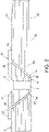
- FIG. 2 is a diagram representing a sectional view of a completed single-sided pre-cured plug repair that entailed machining of a conical cavity 6a in a composite laminate 2 followed by installation of a conical pre-cured plug 4 (hereinafter "conical plug 4") in the conical cavity 6a.
- conical cavity means a through hole or partial-depth recess having the shape of a truncated cone (e.g., a frustum).
- the term “conical plug” means a plug having the shape of a truncated cone. In the example depicted in FIG.
- the conical plug 4 has a countersunk through hole 3 with a chamfer 5 for receiving the tapered head of a fastener (not shown).
- the conical cavity 6a is bounded by a conical internal surface 36 that extends from a first opening at the OML surface 24 to a second opening at the IML surface 28 of the composite laminate 2.
- the conical plug 4 is a composite laminate comprising a stack of fiber-reinforced plies 32 having different fiber orientations. More specifically, each fiber-reinforced ply 32 comprises a respective plurality of mutually parallel fibers embedded in an epoxy matrix.
- the fibers of conical plug 4 are made of the same material (e.g., carbon or fiberglass) as the material of the fibers of the composite laminate 2.
- the OML and IML surfaces of conical plug 4 are respectively flush with the OML and IML surfaces 24 and 28 of the composite laminate 2.
- the conical plug 4 has a conical surface 38 which opposes and is surrounded by the conical internal surface 36 of the composite laminate 2.
- the conical surface 38 of conical plug 4 is bonded to the conical internal surface 36 of the composite laminate 2 by adhesive 7a.
- a pre-cured patch 34 is shown bonded by adhesive 7b to the OML surface of conical plug 4 and to the OML surface 24 of composite laminate 2.
- the pre-cured patch 34 is optional.
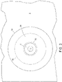
- FIG. 3 is a diagram representing a top view of the assembly depicted in FIG. 2 .
- the pre-cured patch 34 is circular.
- the conical internal surface 36 which bounds the conical cavity 6a, extends from a circular opening 48 (indicated by a dashed circle in FIG. 3 ) at the OML surface 24 of composite laminate 2 to a circular opening 50 (indicated by a dashed circle in FIG. 3 ) at the IML surface 28 of composite laminate 2.
- the circular opening 50 at the IML surface 28 has a radius which is less than the radius of the circular opening 48 at the OML surface 24.
- the conical cavity may be a conical recess that does not extend through the entire depth of the composite laminate 2, in which case the height of the conical plug may be reduced.
- the damaged area 8 is removed from the edge band 1 of composite laminate 2 by machining a double-conical cavity instead of a simple conical cavity.
- This process involves machining one side of the composite laminate 2 using a tapered router bit and then machining the other side of the composite laminate 2 using the same tapered router bit.
- double-conical cavity means a cavity having the shape of two truncated cones (e.g., two frustums) sharing a common plane of truncation.
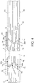
- FIG. 4 is a diagram representing a sectional view of a completed double-sided pre-cured plug repair which entailed machining a double- conical cavity 6b in a composite laminate 2 followed by installation of a pair of conical pre-cured plugs 4a and 4b (hereinafter "conical plugs 4a and 4b") in respective spaces of the double-conical cavity 6b.
- the upper space of the double-conical cavity 6b is bounded by a first conical internal surface 36a that extends from an opening at the OML surface 24 of composite laminate 2; the lower space of the double-conical cavity 6b is bounded by a second conical internal surface 36b that extends from an opening at the IML surface 28 of composite laminate 2.
- the conical plugs 4a and 4b are respective composite laminates, each composite laminate comprising a stack of fiber-reinforced plies 32 as previously described.
- the conical plugs 4a and 4b have respective portions of a countersunk through hole 3 with a chamfer 5 for receiving the tapered head of a fastener (not shown).
- the OML surface of conical plug 4a is flush with the OML surface 24 of composite laminate 2; the IML surface of conical plug 4b is flush with the IML surface 28 of composite laminate 2. As seen in FIG.
- the conical plug 4a has a conical surface 38a which opposes and is surrounded by the conical internal surface 36a of composite laminate 2;
- the conical plug 4b has a conical surface 38b which opposes and is surrounded by the conical internal surface 36b of composite laminate 2
- the conical surface 38a of conical plug 4a is bonded to the conical internal surface 36a of composite laminate 2 by adhesive 7a
- the conical surface 38b of conical plug 4b is bonded to the conical internal surface 36b of composite laminate 2 by adhesive 7c.
- the opposing surfaces of conical plugs 4a and 4b are bonded to each other by adhesive 7d. All of the adhesive 7a, 7c, and 7d is cured at the same time.
- the pre-cured patch 34 is bonded by adhesive 7b to the OML surface of conical plug 4a and to the OML surface 24 of composite laminate 2.
- the damaged area 8 is removed from the edge band 1 of composite laminate 2 by machining a tapered slot which extends all the way to the edge 30. This process involves machining one side of the composite laminate 2 using a tapered router bit.
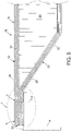
- FIG. 5 is a diagram representing a sectional view of an assembly 10 comprising a honeycomb panel 12 having an edge band 1 which is fastened to a part 14 by fasteners not shown. Whereas the assembly 10 depicted in FIG. 1 was sectioned in a plane that intersected a fastener, FIG. 5 shows an assembly which has been sectioned in an edge band area disposed between two adjacent fasteners.
- the honeycomb panel 12 includes an upper facesheet 22, a lower facesheet 26, and a low-density core 20.
- the plies 32 of upper facesheet 22 and lower facesheet 26 form the composite laminate 2.
- the edge 30 of composite laminate 2 forms the outer boundary of edge band 1.
- the external surface of upper facesheet 22 forms the OML surface 24 of honeycomb panel 12; the external surface of lower facesheet 26 forms the IML surface 28 of honeycomb panel 12.
- the composite laminate 2 includes a damaged area 8 which extends from the vertical dashed line to the edge 30 of composite laminate 2.
- any coating e.g., paint
- the damaged portion of the composite material is removed by machining.
- a tapered router bit is used to form a tapered slot having a predefined shape and taper angle, which tapered slot extends all the way to the edge 30 and through the entire depth of the composite laminate.
- a tapered slot that does not extend to the edge 30 may be used in place of a conical cavity. Instead of a full-depth tapered slot, the damaged material may be removed by machining a partial-depth tapered recess.
- the next step is to create a tapered plug having a size and shape which match the size and shape of the tapered slot using pre-cured shim stock made of similar material. More specifically, the size of the tapered plug is slightly smaller than the size of the tapered slot to enable the tapered plug to fit in the tapered slot.
- the tapered plug can be either machined down from stock repair material to the correct thickness and profile or machined specifically for a particular slot. After machining, the tapered plug is bonded in the tapered slot using glue or adhesive (paste or film). If the original damaged area 8 included a fastener through hole, then a fastener through hole having the same configuration as the original fastener through hole is drilled in the tapered plug after installation. Thereafter, a new coating is applied on the OML of the tapered plug and surrounding OML surface of the honeycomb panel 12. The finished honeycomb panel 12 is then transported to the location of the aircraft and reinstalled on the aircraft using fasteners.
- a thin pre-cured repair patch (overlying and extending beyond the pre-cured plug) may be bonded to the pre-cured plug and to the surrounding portion of the OML surface of composite laminate 2 to provide additional retention force to the final installed repair.
- the new coating is applied on the OML of the pre-cured repair patch.
- FIG. 6 is a diagram representing a sectional view of a completed single-sided pre-cured plug repair that entailed machining of a tapered slot 42a in a composite laminate 2 followed by installation of a pre-cured tapered plug 40 (hereinafter "tapered plug 40") in the tapered slot 42a.
- the tapered slot 42a is bounded by a tapered internal surface 44 that extends to the edge 30.
- the tapered slot 42a is a composite laminate comprising a stack of fiber-reinforced plies 32 having different fiber orientations, as previously described.
- the tapered plug 40 has a tapered surface 46 which opposes the tapered internal surface 44 of the composite laminate 2.
- tapered surface 46 of tapered plug 40 is bonded to the tapered internal surface 44 of composite laminate 2 by adhesive 7a.
- a pre-cured patch 34 is shown bonded by adhesive 7b to the OML surface of tapered plug 40 and to the OML surface 24 of composite laminate 2.
- FIG. 7 is a diagram representing a top view of the assembly depicted in FIG. 6 .
- tapered internal surface 44 which bounds the tapered slot 42a, extends from an opening 52 (indicated by a dashed line in FIG. 7 ) at the OML surface 24 of composite laminate 2 to an opening 54 (indicated by a dash-dot line in FIG. 7 ) at the IML surface 28 of composite laminate 2.
- the opening 54 at the IML surface 28 has a width and a radius which are respectively less than the width and radius of the opening 52 at the OML surface 24.
- the damaged area 8 depicted in FIG. 5 is removed from the edge band 1 of composite laminate 2 by machining a double-tapered slot instead of a simple tapered slot.
- This process involves machining one side of the composite laminate 2 using a tapered router bit and then machining the other side of the composite laminate 2 using the same tapered router bit.
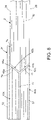
- FIG. 8 is a diagram representing a sectional view of a completed double-sided pre-cured plug repair achieved by first machining a double-tapered slot 42b in composite laminate 2 and then installing a pair of tapered pre-cured plugs 40a and 40b (hereinafter "tapered plugs 40a and 40b") in respective spaces of the double-tapered slot 42b.
- the upper space of the double-tapered slot 42b is bounded by a first tapered internal surface 44a that extends from an opening at the OML surface 24 of composite laminate 2; the lower space of the double-tapered slot 42b is bounded by a second tapered internal surface 44b that extends from an opening at the IML surface 28 of composite laminate 2.
- the tapered plugs 40a and 40b are respective composite laminates, each composite laminate comprising a stack of fiber-reinforced plies 32 as previously described.
- the tapered plug 40a has a tapered surface 46a which opposes and is bonded to the tapered internal surface 44a of composite laminate 2; the tapered plug 40b has a tapered surface 46b which opposes and is bonded to the tapered internal surface 44b of composite laminate 2
- the tapered surface 46a of tapered plug 40a is bonded to the tapered internal surface 44a of composite laminate 2 by adhesive 7a, while the tapered surface 46b of tapered plug 40b is bonded to the tapered internal surface 44b of composite laminate 2 by adhesive 7c.
- the opposing surfaces of tapered plugs 40a and 40b are bonded to each other by adhesive 7d. All of the adhesive 7a, 7c, and 7d is cured at the same time.
- the pre-cured patch 34 is bonded by adhesive 7b to the OML surface of tapered plug 40a and to the OML surface 24 of composite laminate 2.
- FIG. 9 is a diagram identifying steps of a method 100 for repairing a composite structure using a pre-cured conical plug of the type depicted in FIG. 2 .
- Method 100 begins by removing paint and primer from above the area of the composite structure to be repaired (step 102). Then a cone-shaped custom router bit is used to remove material from the area to be repaired and machine a tapered internal surface (step 104).
- composite material is removed from the composite laminate to form a conical cavity bounded by a conical internal surface that extends from one opening at the OML surface to the other opening at the IML surface of the composite laminate.
- a conical plug is fitted into the conical cavity such that a conical surface of the plug opposes the conical internal surface of the machined composite laminate and then the projecting portions of the plug are machined to reduce the respective distances by which the plug projects beyond the OML and IML surfaces of the composite laminate skin (step 106).
- the conical plug may be rough trimmed so that a 0.1-inch thickness of plug material protrudes from both sides (OML and IML) of the composite laminate skin.
- the conical plug is then removed from conical cavity and wrapped with film adhesive (step 108). Thereafter, the plug with adhesive is inserted back into the cavity (step 110).
- the conical surface of the plug is then bonded to the conical internal surface of the composite laminate.
- a heat blanket repair stack is placed over the large side (OML) of the conical plug (including a layer of bleeder material between the heat blanket and the plug) and then covered with a vacuum bag (step 112).
- the other side (IML) of the plug is bagged using the same vacuum source (step 114). Thereafter, vacuum pressure and heat are applied to cure the adhesive in accordance with adhesive manufacturer specifications (step 116).
- the plug is sanded flush with the OML and IML surfaces of the composite laminate (step 118). Then a pre-cured overlay ply or patch is applied to the OML of the plug and surrounding portion of the composite laminate (step 120).
- An overlay patch may be applied by placing adhesive between the patch and plug and then curing the adhesive.
- the finishes are then restored (step 122).
- the material removed in step 104 included a through hole for a fastener, a new through hole may be drilled in the plug after sanding and before the finishes are restored.
- the plug may be made of the same composite material that is being repaired (i.e., the same fibers, same epoxy resin, and same distribution of fibers in the epoxy matrix). More specifically, the thicknesses and fiber orientations of the plies of the patch may match the thicknesses and fiber orientations of the plies of the composite material. The fiber orientations in the portions of the plies removed may have different orientations. Each ply may have an orientation that is selected to achieve a particular property or properties. For example, the orientations may be selected to provide properties such as a desired strength, durability, and other suitable features. Preferably, the plies installed have the same orientation, thickness, and materials as the plies removed.
- any alphabetic ordering of steps is for the sole purpose of enabling subsequent short-hand references to antecedent steps and not for the purpose of limiting the scope of the claim to require that the method steps be performed in alphabetic order.
- composite laminate refers to a composite laminate that has been cured or pre-cured, while the term “tapered” excludes stepped.
Landscapes
- Engineering & Computer Science (AREA)
- Mechanical Engineering (AREA)
- Manufacturing & Machinery (AREA)
- Transportation (AREA)
- Aviation & Aerospace Engineering (AREA)
Applications Claiming Priority (1)
| Application Number | Priority Date | Filing Date | Title |
|---|---|---|---|
| US202163174490P | 2021-04-13 | 2021-04-13 |
Publications (1)
| Publication Number | Publication Date |
|---|---|
| EP4074499A1 true EP4074499A1 (fr) | 2022-10-19 |
Family
ID=80952321
Family Applications (1)
| Application Number | Title | Priority Date | Filing Date |
|---|---|---|---|
| EP22164482.6A Pending EP4074499A1 (fr) | 2021-04-13 | 2022-03-25 | Procédés de réparation de matériaux composites utilisant des bouchons prédurcis |
Country Status (5)
| Country | Link |
|---|---|
| US (1) | US12134240B2 (fr) |
| EP (1) | EP4074499A1 (fr) |
| JP (1) | JP2022162971A (fr) |
| CN (1) | CN115196037A (fr) |
| CA (1) | CA3153316A1 (fr) |
Families Citing this family (3)
| Publication number | Priority date | Publication date | Assignee | Title |
|---|---|---|---|---|
| US11661905B1 (en) * | 2022-01-17 | 2023-05-30 | Florida Turbine Technologies, Inc. | 2D variable-area plug nozzle |
| US20240342842A1 (en) * | 2023-04-12 | 2024-10-17 | The Boeing Company | Composite structure repair system |
| CN117212605A (zh) * | 2023-09-19 | 2023-12-12 | 国电环境保护研究院有限公司 | 管道切割取样后内压反向密封固定修复方法 |
Citations (6)
| Publication number | Priority date | Publication date | Assignee | Title |
|---|---|---|---|---|
| US5190611A (en) * | 1991-02-13 | 1993-03-02 | The Boeing Company | Bearing load restoration method for composite structures |
| US6174392B1 (en) * | 1999-03-04 | 2001-01-16 | Northrop Grumman Corporation | Composite structure repair process |
| US20160159057A1 (en) * | 2014-12-05 | 2016-06-09 | The Boeing Company | Forming of staged thermoset composite materials |
| US20170274485A1 (en) * | 2014-08-28 | 2017-09-28 | Safran Aircraft Engines | Repair of an assembly comprising a main body and a reinforcement |
| FR3092787A1 (fr) * | 2019-02-18 | 2020-08-21 | Safran Aircraft Engines | Réparation ou reprise de fabrication d’une pièce en matériau composite à renfort fibreux tissé tridimensionnel |
| EP3750698A1 (fr) * | 2018-09-12 | 2020-12-16 | Mitsubishi Heavy Industries, Ltd. | Timbre de réparation, procédé de moulage de timbre de réparation et procédé de réparation pour matériau composite |
Family Cites Families (12)
| Publication number | Priority date | Publication date | Assignee | Title |
|---|---|---|---|---|
| US8209838B2 (en) | 2008-12-19 | 2012-07-03 | The Boeing Company | Repairing composite structures |
| CN102649342A (zh) * | 2011-02-24 | 2012-08-29 | 成都飞机工业(集团)有限责任公司 | 一种碳纤维增强树脂基层压板局部损伤挖补修补方法 |
| JP5818700B2 (ja) * | 2012-01-19 | 2015-11-18 | 三菱航空機株式会社 | ハニカムサンドイッチ構造体の補修方法及び補修構造 |
| US9849640B2 (en) | 2012-03-28 | 2017-12-26 | Bell Helicopter Textron Inc. | Processes for repairing complex laminated composites |
| JP2014188996A (ja) * | 2013-03-28 | 2014-10-06 | Mitsubishi Aircraft Corp | ハニカムコアサンドイッチ構造体の修理方法および修理結果物 |
| US9539798B2 (en) | 2014-02-17 | 2017-01-10 | The Boeing Company | Verifiable quick patch repair for composite structures |
| US9545782B2 (en) * | 2014-05-13 | 2017-01-17 | The Boeing Company | Method and apparatus for repairing composite materials |
| US10213964B2 (en) * | 2015-05-08 | 2019-02-26 | The Boeing Company | Methods and apparatus for repairing composite materials |
| US10744747B2 (en) * | 2015-07-27 | 2020-08-18 | The Boeing Company | Repairing a contoured composite panel |
| US10293576B2 (en) * | 2017-04-26 | 2019-05-21 | The Boeing Company | Repair patch for composite structure and associated method |
| US10710352B2 (en) | 2017-07-11 | 2020-07-14 | The Boeing Company | Structural pre-cured repair patch for repair to highly loaded primary and secondary structural components |
| US10589505B2 (en) | 2017-11-29 | 2020-03-17 | The Boeing Company | Structural rework of cellular core panels |
-
2022
- 2022-03-05 US US17/687,618 patent/US12134240B2/en active Active
- 2022-03-09 JP JP2022036089A patent/JP2022162971A/ja active Pending
- 2022-03-18 CA CA3153316A patent/CA3153316A1/fr active Pending
- 2022-03-25 EP EP22164482.6A patent/EP4074499A1/fr active Pending
- 2022-04-12 CN CN202210380529.5A patent/CN115196037A/zh active Pending
Patent Citations (6)
| Publication number | Priority date | Publication date | Assignee | Title |
|---|---|---|---|---|
| US5190611A (en) * | 1991-02-13 | 1993-03-02 | The Boeing Company | Bearing load restoration method for composite structures |
| US6174392B1 (en) * | 1999-03-04 | 2001-01-16 | Northrop Grumman Corporation | Composite structure repair process |
| US20170274485A1 (en) * | 2014-08-28 | 2017-09-28 | Safran Aircraft Engines | Repair of an assembly comprising a main body and a reinforcement |
| US20160159057A1 (en) * | 2014-12-05 | 2016-06-09 | The Boeing Company | Forming of staged thermoset composite materials |
| EP3750698A1 (fr) * | 2018-09-12 | 2020-12-16 | Mitsubishi Heavy Industries, Ltd. | Timbre de réparation, procédé de moulage de timbre de réparation et procédé de réparation pour matériau composite |
| FR3092787A1 (fr) * | 2019-02-18 | 2020-08-21 | Safran Aircraft Engines | Réparation ou reprise de fabrication d’une pièce en matériau composite à renfort fibreux tissé tridimensionnel |
Also Published As
| Publication number | Publication date |
|---|---|
| CA3153316A1 (fr) | 2022-10-13 |
| JP2022162971A (ja) | 2022-10-25 |
| US20220324186A1 (en) | 2022-10-13 |
| US12134240B2 (en) | 2024-11-05 |
| CN115196037A (zh) | 2022-10-18 |
Similar Documents
| Publication | Publication Date | Title |
|---|---|---|
| EP4074499A1 (fr) | Procédés de réparation de matériaux composites utilisant des bouchons prédurcis | |
| CA2831084C (fr) | Methode de reparation, de raccordement, de jointage, d'usinage et de stabilisation d'une alveole au moyen d'une mousse structuree versable et structure integrant celle-ci | |
| US9393768B2 (en) | Discretely tailored multi-zone bondline for fail-safe structural repair | |
| US20170028670A1 (en) | Composite structure | |
| CA2831088A1 (fr) | Methode de reparation, de raccordement, de jointage, d'usinage et de stabilisation d'une alveole au moyen d'une mousse structuree versable et structure integrant celle-ci | |
| US20050006526A1 (en) | Method fo forming and indirect testing of a bond on or in an aircraft component | |
| CA2831097C (fr) | Methode de reparation, de raccordement, de jointage, d'usinage et de stabilisation d'une alveole au moyen d'une mousse structuree versable et structure integrant celle-ci | |
| US20230158759A1 (en) | Locking hole plug for sealing holes in composite structures | |
| JP7036694B2 (ja) | 修理パッチ及び複合材の修理方法 | |
| EP3009259B1 (fr) | Procédé de réparation d'une structure raidie par un noyau | |
| US20150064393A1 (en) | Laminate for joining parts, and method and system for joining parts | |
| US11440277B2 (en) | Method of repairing composite sandwich panels | |
| US11673644B2 (en) | Composite spars with integrated sacrificial surfaces | |
| US20140119930A1 (en) | Method of Repairing, Splicing, Joining, Machining, and Stabilizing Honeycomb Core Using Pourable Structural Foam and a Structure Incorporating the Same | |
| JP2019072947A (ja) | 修理パッチ、修理パッチの成形方法、複合材の修理方法及び成形治具 | |
| KR102038297B1 (ko) | 복합재 일체형 연료탱크의 수리 방법 | |
| US11981426B2 (en) | Composite spars with integrated sacrificial surfaces | |
| US9333684B2 (en) | Method of repairing, splicing, joining, machining, and stabilizing honeycomb core using pourable structural foam and a structure incorporating the same | |
| EP4559667A1 (fr) | Procédé de réparation d'un élément en matériau composite | |
| US20150136308A1 (en) | Field repair kits for structural panel | |
| CN120553138A (zh) | 飞机机翼蒙皮的修补方法 |
Legal Events
| Date | Code | Title | Description |
|---|---|---|---|
| PUAI | Public reference made under article 153(3) epc to a published international application that has entered the european phase |
Free format text: ORIGINAL CODE: 0009012 |
|
| STAA | Information on the status of an ep patent application or granted ep patent |
Free format text: STATUS: THE APPLICATION HAS BEEN PUBLISHED |
|
| AK | Designated contracting states |
Kind code of ref document: A1 Designated state(s): AL AT BE BG CH CY CZ DE DK EE ES FI FR GB GR HR HU IE IS IT LI LT LU LV MC MK MT NL NO PL PT RO RS SE SI SK SM TR |
|
| RAP3 | Party data changed (applicant data changed or rights of an application transferred) |
Owner name: THE BOEING COMPANY |
|
| STAA | Information on the status of an ep patent application or granted ep patent |
Free format text: STATUS: REQUEST FOR EXAMINATION WAS MADE |
|
| 17P | Request for examination filed |
Effective date: 20230401 |
|
| RBV | Designated contracting states (corrected) |
Designated state(s): AL AT BE BG CH CY CZ DE DK EE ES FI FR GB GR HR HU IE IS IT LI LT LU LV MC MK MT NL NO PL PT RO RS SE SI SK SM TR |
|
| STAA | Information on the status of an ep patent application or granted ep patent |
Free format text: STATUS: EXAMINATION IS IN PROGRESS |
|
| 17Q | First examination report despatched |
Effective date: 20250910 |