EP4074583B1 - Dispositif formant roue auxiliaire pour engins de traction et système d'engin de traction - Google Patents
Dispositif formant roue auxiliaire pour engins de traction et système d'engin de traction Download PDFInfo
- Publication number
- EP4074583B1 EP4074583B1 EP21000106.1A EP21000106A EP4074583B1 EP 4074583 B1 EP4074583 B1 EP 4074583B1 EP 21000106 A EP21000106 A EP 21000106A EP 4074583 B1 EP4074583 B1 EP 4074583B1
- Authority
- EP
- European Patent Office
- Prior art keywords
- auxiliary wheel
- tractor
- wheel
- auxiliary
- suspension
- Prior art date
- Legal status (The legal status is an assumption and is not a legal conclusion. Google has not performed a legal analysis and makes no representation as to the accuracy of the status listed.)
- Active
Links
Images


Classifications
-
- B—PERFORMING OPERATIONS; TRANSPORTING
- B62—LAND VEHICLES FOR TRAVELLING OTHERWISE THAN ON RAILS
- B62D—MOTOR VEHICLES; TRAILERS
- B62D49/00—Tractors
- B62D49/08—Tractors having means for preventing overturning or tipping
-
- B—PERFORMING OPERATIONS; TRANSPORTING
- B62—LAND VEHICLES FOR TRAVELLING OTHERWISE THAN ON RAILS
- B62D—MOTOR VEHICLES; TRAILERS
- B62D61/00—Motor vehicles or trailers, characterised by the arrangement or number of wheels, not otherwise provided for, e.g. four wheels in diamond pattern
- B62D61/12—Motor vehicles or trailers, characterised by the arrangement or number of wheels, not otherwise provided for, e.g. four wheels in diamond pattern with variable number of ground engaging wheels, e.g. with some wheels arranged higher than others, or with retractable wheels
-
- A—HUMAN NECESSITIES
- A01—AGRICULTURE; FORESTRY; ANIMAL HUSBANDRY; HUNTING; TRAPPING; FISHING
- A01B—SOIL WORKING IN AGRICULTURE OR FORESTRY; PARTS, DETAILS, OR ACCESSORIES OF AGRICULTURAL MACHINES OR IMPLEMENTS, IN GENERAL
- A01B3/00—Ploughs with fixed plough-shares
- A01B3/46—Ploughs supported partly by tractor and partly by their own wheels
Definitions
- the present invention relates to an auxiliary wheel device for tractors and a tractor system.
- Support and transport wheels for mounted reversible plows are state of the art.
- Support wheels are usually arranged at the end of a plow on its frame and swing automatically from one working position to another when the plow is turned. At the end of a field or during transport, such support wheels remain on the frame and are raised with the plow.
- support wheels are used to control the depth of the plow body during plowing.
- Transport wheels are particularly well-known in multi-furrow mounted reversible plows in order to support part of the weight of the raised multi-furrow mounted reversible plow during transport.
- a pendulum feeler and transport wheel for multi-blade three-point reversible plows is known.
- the pendulum feeler and transport wheel is arranged at the rear of the plow frame.
- a ploughing depth can be adjusted by adjusting the pendulum feeler and transport wheel relative to the plow frame.
- the pendulum feeler and transport wheel automatically changes to a new working position when the three-point reversible plow is lifted and turned by a tractor hydraulic system.
- the pendulum feeler and transport wheel can be locked in a transport position for road transport.
- a support wheel attachment with a support wheel is known, which is detachably attached to a plough frame by means of a fastening plate and supports the plough on the ground.
- the support wheel is pivoted about an axis arranged on the frame.
- the pivoting range of the support wheel is limited to 180° by stops on the plough side.
- the support wheel attachment has a clamping device by means of which a height adjustment of the
- the support wheel attachment also has a support wheel fork that can rotate freely about a rotation axis. This free rotation is desirable for a transport position of the support wheel, in which the pivoting of the support wheel about the axis is switched off by means of a locking device.
- the object of the invention is therefore to provide an improved auxiliary wheel device and in particular an improved auxiliary wheel device for tractors and tractor systems with heavy attachments.
- an auxiliary wheel device for tractors according to claim 1 is proposed.
- the auxiliary wheel device according to the invention comprises in particular at least a first auxiliary wheel and a wheel suspension.
- the wheel suspension can have a first axis of rotation about which the first auxiliary wheel is rotatably mounted.
- the wheel suspension can have a second axis of rotation about which the first auxiliary wheel is steerably mounted.
- the auxiliary wheel device according to the invention comprises a fastening device for detachable fastening to the tractor.
- a tractor generally means a motor-driven land-based towing vehicle, e.g. a tractor, for towing wagons, trailers, low-loaders, semi-trailers, agricultural implements, ballasts and other non-powered vehicles.
- a tractor with at least one attached wagon, trailer, low-loader, semi-trailer, agricultural implement, ballasts or other non-powered vehicle is hereinafter referred to as a combination.
- Tractors are generally characterized by various connection points or attachment points, also called trailer couplings, for pulling or driving agricultural attachments.
- Agricultural attachments include, for example, ploughs, harrows, cultivators, sowing machines, rakes, mowers, etc.
- the attachment points include, for example, trailer couplings at the front and rear by means of bolts, drawbars, Hitch hook, Piton-Fix, ball head coupling, three-point hydraulics, quick coupling triangle, fifth wheel coupling and/or coupling rail or towing bracket.
- Attachments and ballast can affect the driving characteristics of a tractor.
- permissible axle loads a maximum permissible total weight and a tire load capacity of the tractor must not be exceeded when driving on the road.
- a front axle of the tractor should be loaded with at least 20% of the tractor's unladen weight in order to ensure sufficient steering effect of the front axle even with attachments attached to the rear. Exceeding this limit may be permissible during field use if a tractor manufacturer specifies higher technical axle loads or a higher technical total weight.
- Heavy attachments are in particular those which, when attached to the rear of the tractor in field use, for example a plough in a working position, relieve the load on the front axle to such an extent that less than 20% of the unladen weight is on the front axle.
- ballast was traditionally arranged on the front of the tractor and/or the heavy attachments were equipped with a fixed, i.e. non-removable, supporting support wheel and/or transport wheel.
- a heavy attachment may have to be lifted in order to turn the tractor and the attachment.
- a conventional support wheel can no longer fulfill its supporting function precisely when it is particularly necessary to maintain the tractor's ability to steer.
- the auxiliary wheel device according to the invention is preferably attached directly to the tractor, in particular to a rear of the tractor, so that it does not have to be lifted together with the heavy attachment, for example at one end of the field. Rather, the auxiliary wheel device according to the invention can support the front axle in such a way, i.e. load it with at least 20% of the tractor's empty weight, that the tractor's ability to steer is maintained.
- auxiliary wheel device makes it possible to transport the heavy attachment, in particular without coupling to an articulated trailer coupling, but simply by lifting or unlifting the heavy attachment, whereby the auxiliary wheel device according to the invention can passively steer the tractor when cornering, simultaneously relieving the rear axle of the towing vehicle and loading the front axle of the towing vehicle.
- the fastening device can comprise a trailer device. It can also be preferred that the fastening device comprises a slide plate for fastening to a trailer bracket of the tractor.
- the design of the fastening device as a trailer device essentially has the advantage of universal compatibility with tractors from different manufacturers.
- the design as a slide plate for fastening to a trailer bracket or a slide guide of the tractor essentially enables the simultaneous use of other trailer devices of the tractor.
- the auxiliary wheel device according to the invention can be attached to the trailer bracket and at the same time a mounted reversible plow can be attached to the three-point hydraulics of the tractor.
- the slide plate can be mounted on the slide guide in a height-adjustable manner, for example in order to individually adjust the auxiliary wheel device according to the invention to a tractor.
- the slide plate engages in the slide guide in particular in a form-fitting manner.
- the slide plate and the slide guide can be detachably connected to one another by means of one or more bolts or screw bolts.
- the wheel suspension can comprise a steering column that supports the first auxiliary wheel so that it can be steered about the second axis of rotation.
- the wheel suspension can also comprise a steering axle, at the distal end of which the auxiliary wheel can be arranged so that it can rotate about the first axis of rotation.
- the steering axle engages the steering column at its proximal end so that it can rotate about the second axis of rotation.
- the wheel suspension can also comprise a friction element that engages the steering axle in a frictional manner.
- a helical tension spring is arranged in particular eccentrically at the proximal end and so that it engages the wheel suspension in order to preload the friction element against the steering axle.
- the wheel suspension essentially comprises at least one first swing arm, also called a longitudinal control arm, which movably suspends the first auxiliary wheel.
- the swing arm can be hinged at one end to the fastening device. At its other end, the swing arm can be arranged on the steering column.
- the wheel suspension can comprise at least one second and/or third and/or fourth swing arm, which movably suspend the first auxiliary wheel.
- the swing arms can be hinged at one end to the fastening device and at their other ends connected to one another and/or connected in an articulated manner via one or more struts.
- the fastening device, the rockers and/or the one or more struts can preferably form a closed kinematic chain.
- the wheel suspension further comprises an actuator for moving the first auxiliary wheel relative to a surface.
- the actuator comprises in particular a linear motor, a hydraulic cylinder or the like.
- the hydraulic cylinder can be articulated at one end to the fastening device or at one end of the at least one swing arm and at its other end to another end of the second swing arm, to a strut or to the steering column.
- the hydraulic cylinder can raise or lower the first auxiliary wheel relative to the tractor or relative to the surface.
- the hydraulic cylinder can be controlled in particular from the driver's cab of the tractor.
- the contact pressure of the first auxiliary wheel on the surface can be adjusted by means of a pressure relief valve and/or a pressure accumulator for hydraulic fluid.
- the first and second axes of rotation are preferably arranged in relation to one another in such a way that they cause the first auxiliary wheel to caster.
- the component of a vector from a wheel contact point to a point through which the steering axis or second axis of rotation passes through the road surface in the direction of an intersection line between the wheel center plane and the road is generally referred to as caster or caster distance.
- the wheel contact point is preferably located behind the point through which the steering axis or second axis of rotation passes in the direction of travel, also referred to as positive caster, so that the first auxiliary wheel follows the second axis of rotation.
- the caster can generate a torque when cornering that is directed opposite to this as a restoring torque. This causes the auxiliary wheel device to steer back automatically to a straight-ahead position. Caster generally improves the straight-ahead travel of the first auxiliary wheel.
- the auxiliary wheel device can have a second auxiliary wheel, which is arranged in particular at an acute angle to the first auxiliary wheel in order to effect a toe-in.
- a tractor system according to claim 8 which in particular comprises a tractor and the auxiliary wheel device according to the invention.
- the auxiliary wheel device 100 comprises a first 102, a second auxiliary wheel 104, a wheel suspension 106 and a slide plate 108.
- the slide plate 108 serves for the removable attachment of the auxiliary wheel device 100 to a trailer bracket with slide guides (see Fig. 2 ), whereby the trailer bracket is arranged at the rear of a tractor.
- the carriage plate 108 comprises four bolts 110 which engage in corresponding holes in the carriage guides.
- the wheel suspension 106 further comprises a steering column 112 and a steering axle 114.
- the steering axle 114 engages at one end in the steering column 112 so as to be rotatable about an axis of rotation 116.
- the auxiliary wheels 102, 104 are arranged on both sides so as to be rotatable about an axis of rotation 118.
- the wheel suspension 106 also includes a first 120 and a second U-shaped swing arm 122.
- the first U-shaped swing arm 120 is hinged at one end to the slide plate 108.
- the second U-shaped swing arm 122 is also hinged at one end to the slide plate 108.
- the articulations of the U-shaped swing arms 120, 122 on the slide plate 108 are spaced apart from one another.
- the wheel suspension 106 also includes a V-shaped strut 124.
- the first U-shaped swing arm 120 is hinged at its other end to one end of the V-shaped strut 124.
- the second U-shaped swing arm 122 is hinged at its other end to the other end of the V-shaped strut 124.
- the slide plate 108, the two U-shaped rockers 120, 122 and the V-shaped strut 124 form a closed kinematic chain and resemble a parallelogram with joints at the corners.
- a yoke-like strut 126 is arranged at the other end of the second U-shaped swing arm 122 and reinforces an open side of the U of the U-shaped swing arm 122.
- Two double-acting hydraulic cylinders 128, 130 are arranged on both sides of the wheel suspension 106. First ends of the hydraulic cylinders 128, 130 are each hinged on both sides of the first end of the first U-shaped swing arm 120. Other ends of the hydraulic cylinders 128, 130 are each hinged to the ends of the yoke-like strut 126.
- the hydraulic cylinders 128, 130 are arranged similar to a parallelogram diagonal.
- double-acting hydraulic cylinders 128, 130 retract, they move the parallelogram or the wheel suspension in such a way that the auxiliary wheels 102, 104 are lifted off a surface 136 (see Fig. 1B ) are raised. If the double-acting hydraulic cylinders 128, 130 extend, they move the parallelogram or the wheel suspension in such a way that the auxiliary wheels 102, 104 rest on the ground 136 (see Fig. 1B ) can be lowered.
- Attachments and ballast can affect the driving characteristics of the tractor.
- the permissible axle loads, the maximum permissible total weight and the tractor's tire load capacity must not be exceeded when driving on the road.
- the front axle of the tractor should be loaded with at least 20% of the tractor's unladen weight in order to ensure sufficient steering of the front axle even with attachments attached to the rear. Exceeding this limit may be permissible when used in the field if a tractor manufacturer specifies higher technical axle loads or a higher technical total weight.
- Heavy attachments are those in particular which, when attached to the rear of the tractor in the field, for example a plough in a working position, relieve the load on the front axle to such an extent that less than 20% of the unladen weight is on the front axle.
- ballasting was traditionally arranged on the front of the tractor and/or the heavy attachments were equipped with a fixed, i.e. non-removable, supporting support wheel and/or transport wheel.
- a heavy attachment may have to be lifted in order to turn the tractor and the attachment.
- a conventional support wheel can no longer fulfill its supporting function precisely when maintaining the tractor's steerability is particularly necessary.
- the auxiliary wheel device 100 can be connected directly to the tractor, in particular attached to a rear of the tractor, so that it does not have to be lifted together with the heavy attachment, for example at the end of the field. Instead, the auxiliary wheel device 100 can always support the front axle, i.e. load it with at least 20% of the tractor's empty weight, so that the tractor's steerability is maintained.
- Conventional transport wheels of heavy attachments for tractors normally do not have a steering axle, but are unsteered, so that the heavy attachment must be pulled on an articulated trailer coupling for transport to and from the field, while the heavy attachment is typically attached to the three-point hydraulics in the working position.
- the pivot axis 116 of the auxiliary wheel device 100 makes it possible to transport the heavy attachment in particular without coupling to an articulated trailer coupling, but simply by lifting or unlifting the heavy attachment, with the auxiliary wheel device 100 passively steering when the tractor corners, simultaneously relieving the load on the rear axle of the tractor and loading the front axle of the towing vehicle.
- the axis of rotation 116 and the axis of rotation 118 are arranged in such a way that they cause a caster of the auxiliary wheels 102, 104.
- the caster or caster distance is the component of a vector from a wheel contact point to a point where the axis of rotation 116 penetrates the ground 136 (see Fig. 1B ) in the direction of an intersection line between the wheel centre plane and the ground 136 (see Fig. 1B ).
- the wheel contact point is preferably located behind the point of intersection when viewed in the direction of travel, also referred to as positive caster, so that the auxiliary wheels 102, 104 follow the axis of rotation 116.
- the caster can generate a torque when cornering that is directed opposite to this as a restoring torque.
- the auxiliary wheel device 100 automatically steers back to a straight-ahead position. Caster generally improves the straight-ahead travel of the auxiliary wheels 102, 104.
- the auxiliary wheel 102 is arranged at an acute angle to the auxiliary wheel 104 in order to bring about a toe-in.
- the acute angle is, for example, in a range of 1 - 20°, wherein the second auxiliary wheel 104 has a further axis of rotation which is arranged at a correspondingly obtuse angle to the axis of rotation 118.
- the wheel suspension 106 comprises a Friction element 132 which frictionally engages the steering axle 114.
- a helical tension spring 134 is arranged eccentrically at one end of the steering axle 114 and engaging the wheel suspension 106 in order to preload the friction element 132 against the steering axle 114.
- a trailer bracket 200 is shown.
- the trailer bracket has two parallel slide guides 202, each of which has several holes 204.
- a slide plate can be mounted in the slide guides 202 so that it is height-adjustable in order to individually adjust an auxiliary wheel device to a tractor.
- the slide plate engages in the slide guides 202 in a form-fitting manner.
- the slide plate and the slide guides 202 can be detachably connected to one another by means of one or more bolts or screw bolts.
- the trailer bracket 200 is welded or screwed to the tractor at the rear.
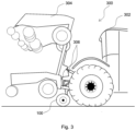
- the towing vehicle system 300 comprises a tractor 302, the auxiliary wheel device 100 and a heavy attachment 304 which is attached to a three-point hydraulic system 306 of the tractor 302.
- the heavy attachment 304 is shown in a raised state or transport state.
- the attachment 304 is so heavy that it would relieve a front axle of the tractor 300 to such an extent that the tractor 302 would no longer have sufficient steering capability.
- the auxiliary wheel device 100 is lowered onto a base 308 and supports the front axle in such a way that the steering capability of the tractor 302 is restored.
Landscapes
- Engineering & Computer Science (AREA)
- Chemical & Material Sciences (AREA)
- Combustion & Propulsion (AREA)
- Transportation (AREA)
- Mechanical Engineering (AREA)
- Vehicle Body Suspensions (AREA)
Claims (8)
- Dispositif à roues auxiliaires (100) conçu pour des tracteurs (302) comportant :au moins une première roue auxiliaire (102, 104) etune suspension de roue (106),dans lequel la suspension de roue (106) présente un premier axe de rotation (118) autour duquel la première roue auxiliaire (102, 104) est montée de manière à pouvoir tourner, etdans lequel la suspension de roue (106) présente un second axe de rotation (116) autour duquel la première roue auxiliaire (102, 104) est montée de manière à pouvoir être dirigée ; etun dispositif de fixation (108) conçu pour la fixation de manière amovible sur le tracteur (302),caractérisé en ce quela suspension de roue (106) comprend un actionneur (128, 130) conçu pour déplacer la première roue auxiliaire (102, 104) par rapport à un sol à l'état monté du dispositif à roues auxiliaires (100).
- Dispositif à roues auxiliaires (100) selon la revendication 1
caractérisé en ce que
le dispositif de fixation (108) comprend un dispositif d'attelage (108). - Dispositif à roues auxiliaires (100) selon la revendication 1 ou 2
caractérisé en ce que
le dispositif de fixation (108) comprend une plaque glissière (108) pour la fixation à un chevalet d'attelage (200) du tracteur (302). - Dispositif à roues auxiliaires (100) selon l'une des revendications précédentes
caractérisé en ce que
la suspension de roue (106) comprend une colonne de direction (112) qui supporte la première roue auxiliaire (102, 104) de manière à pouvoir la diriger autour du second axe de rotation (116). - Dispositif à roues auxiliaires (100) selon l'une des revendications précédentes
caractérisé en ce que
la suspension de roue (106) comprend au moins une première bielle (120, 122) qui suspend de manière mobile la première roue auxiliaire (102, 104). - Dispositif à roues auxiliaires (100) selon l'une des revendications précédentes
caractérisé en ce que
le premier (118) et le second (116) axe de rotation sont disposés l'un par rapport à l'autre de telle sorte qu'ils provoquent une chasse de la première roue auxiliaire (102, 104). - Dispositif à roues auxiliaires (100) selon l'une des revendications précédentes
caractérisé en ce que
le dispositif à roues auxiliaires (104) présente une seconde roue auxiliaire (104) qui est disposée à un angle aigu par rapport à la première roue auxiliaire (102) pour effectuer un pincement. - Système de tracteur (300) comportantun tracteur (302) etun dispositif à roues auxiliaires (100) selon l'une des revendications précédentes.
Priority Applications (1)
| Application Number | Priority Date | Filing Date | Title |
|---|---|---|---|
| EP21000106.1A EP4074583B1 (fr) | 2021-04-16 | 2021-04-16 | Dispositif formant roue auxiliaire pour engins de traction et système d'engin de traction |
Applications Claiming Priority (1)
| Application Number | Priority Date | Filing Date | Title |
|---|---|---|---|
| EP21000106.1A EP4074583B1 (fr) | 2021-04-16 | 2021-04-16 | Dispositif formant roue auxiliaire pour engins de traction et système d'engin de traction |
Publications (3)
| Publication Number | Publication Date |
|---|---|
| EP4074583A1 EP4074583A1 (fr) | 2022-10-19 |
| EP4074583C0 EP4074583C0 (fr) | 2024-12-04 |
| EP4074583B1 true EP4074583B1 (fr) | 2024-12-04 |
Family
ID=75581353
Family Applications (1)
| Application Number | Title | Priority Date | Filing Date |
|---|---|---|---|
| EP21000106.1A Active EP4074583B1 (fr) | 2021-04-16 | 2021-04-16 | Dispositif formant roue auxiliaire pour engins de traction et système d'engin de traction |
Country Status (1)
| Country | Link |
|---|---|
| EP (1) | EP4074583B1 (fr) |
Families Citing this family (1)
| Publication number | Priority date | Publication date | Assignee | Title |
|---|---|---|---|---|
| CN119744579B (zh) * | 2025-02-11 | 2025-06-27 | 江苏金秆农业装备有限公司 | 一种液压翻转犁悬挂装置 |
Family Cites Families (11)
| Publication number | Priority date | Publication date | Assignee | Title |
|---|---|---|---|---|
| DE7014464U (de) | Bayerische Pflugfab Gmbh | Pendeltast- und Transportrad für Dreipunkt-Drehpflüge | ||
| FR1150495A (fr) * | 1956-05-07 | 1958-01-14 | Const Mecaniques Chenard Et Wa | Tracteur, notamment pour outils aratoires |
| DE2362151A1 (de) | 1973-12-14 | 1975-06-26 | Krone Bernhard Gmbh Maschf | Stuetzradbefestigung fuer einen anbaudrehpflug |
| DE4031504C2 (de) | 1990-01-26 | 2003-07-03 | Lemken Gmbh & Co Kg | Aufsatteldrehpflug mit variabler Arbeitsbreiteneinstellung |
| DE29815053U1 (de) | 1998-08-24 | 1998-11-12 | Rabewerk Gmbh + Co, 49152 Bad Essen | Drehpflug mit einem von einem Stabilisator gehaltenen Stützrad |
| FR2783129B1 (fr) | 1998-09-16 | 2000-11-24 | Kuhn Huard Sa | Machine agricole comportant un support de roue directionnel |
| FR2851407B1 (fr) | 2003-02-21 | 2006-03-17 | Naud | Dispositif de fixation d'une roue de terrage au chassis d'une charrue a socs reversibles |
| RU2528484C2 (ru) | 2009-03-21 | 2014-09-20 | Лемкен Гмбх Унд Ко. Кг | Механизм для ведения по глубине оборотного плуга |
| DE102010048287B4 (de) | 2010-10-14 | 2012-06-06 | Lemken Gmbh & Co. Kg | Schwenkstützrad für Anbaudrehpflug |
| DE102014109605B4 (de) | 2014-07-09 | 2018-05-30 | Lemken Gmbh & Co. Kg | Schwenkstützrad zum Anbau an einen Pflugrahmen |
| BE1022805B1 (nl) * | 2015-02-18 | 2016-09-09 | Cnh Industrial Belgium Nv | Steunframe voor landbouwvoertuig |
-
2021
- 2021-04-16 EP EP21000106.1A patent/EP4074583B1/fr active Active
Also Published As
| Publication number | Publication date |
|---|---|
| EP4074583A1 (fr) | 2022-10-19 |
| EP4074583C0 (fr) | 2024-12-04 |
Similar Documents
| Publication | Publication Date | Title |
|---|---|---|
| DE3711317C1 (de) | Landwirtschaftliches Anhaengegeraet | |
| EP4074583B1 (fr) | Dispositif formant roue auxiliaire pour engins de traction et système d'engin de traction | |
| EP3251480B1 (fr) | Remorque et ensemble attelé comprenant un véhicule tracteur et une remorque | |
| EP4101275B1 (fr) | Appareil accessoire destiné au traitement du sol | |
| EP4019301A1 (fr) | Dispositif d'essieu à écartement de la voie variable, véhicule spécial et son utilisation | |
| EP1336549A1 (fr) | Machine agricole remorquée | |
| EP0795265B1 (fr) | Dispositif d'attelage | |
| DE202018000854U1 (de) | Funktionslaufwerk zum Anbau an Off Road Fahrzeuge | |
| EP4074156A1 (fr) | Dispositif timon pour une machine agricole tractée | |
| EP4014708A1 (fr) | Pulvérisateur agricole | |
| DE2948900C2 (de) | Gerätekupplungsvorrichtung für einen Schlepper | |
| EP1714538B1 (fr) | Outil de travail | |
| DE102023106546A1 (de) | Fahrzeuganordnung, Verbindungselement für eine Fahrzeuganordnung und Verfahren zum Betreiben einer Fahrzeuganordnung | |
| DE4208787C2 (de) | Kehrpflug | |
| DE102024119271A1 (de) | Aufsatteldrehpflug | |
| DE69400825T2 (de) | Insbesondere landwirtschaftliches Fahrzeug, umfassend von einem Untergestell getragene Arbeitsorgane und einen Rädersatz, sowie Verbindungsmittel zwischen Untergestell und Rädersatz | |
| EP1623616B1 (fr) | Remorque pour outil agricole de travail du sol | |
| EP1782674B1 (fr) | Faucheuse | |
| DE1151968B (de) | Stuetzstrebe fuer die unteren Hubwerkslenker von Ackerschleppern | |
| DE2618892C3 (de) | Anhänge-Drehpflug für neben der Vorfurche fahrende Schlepper | |
| AT402813B (de) | Zugvorrichtung für einachsige anhänger | |
| DE102024106291A1 (de) | Anhänger | |
| EP1095551A1 (fr) | Machine agricole | |
| DE102004051642A1 (de) | Kopplungs- und Hebevorrichtung für Zugmaschinen, insbesondere Traktoren | |
| DE102006047890A1 (de) | Bodenbearbeitungsgerät mit großer Arbeitsbreite |
Legal Events
| Date | Code | Title | Description |
|---|---|---|---|
| STAA | Information on the status of an ep patent application or granted ep patent |
Free format text: STATUS: UNKNOWN |
|
| PUAI | Public reference made under article 153(3) epc to a published international application that has entered the european phase |
Free format text: ORIGINAL CODE: 0009012 |
|
| STAA | Information on the status of an ep patent application or granted ep patent |
Free format text: STATUS: THE APPLICATION HAS BEEN PUBLISHED |
|
| AK | Designated contracting states |
Kind code of ref document: A1 Designated state(s): AL AT BE BG CH CY CZ DE DK EE ES FI FR GB GR HR HU IE IS IT LI LT LU LV MC MK MT NL NO PL PT RO RS SE SI SK SM TR |
|
| STAA | Information on the status of an ep patent application or granted ep patent |
Free format text: STATUS: REQUEST FOR EXAMINATION WAS MADE |
|
| 17P | Request for examination filed |
Effective date: 20230328 |
|
| RBV | Designated contracting states (corrected) |
Designated state(s): AL AT BE BG CH CY CZ DE DK EE ES FI FR GB GR HR HU IE IS IT LI LT LU LV MC MK MT NL NO PL PT RO RS SE SI SK SM TR |
|
| GRAP | Despatch of communication of intention to grant a patent |
Free format text: ORIGINAL CODE: EPIDOSNIGR1 |
|
| STAA | Information on the status of an ep patent application or granted ep patent |
Free format text: STATUS: GRANT OF PATENT IS INTENDED |
|
| RIC1 | Information provided on ipc code assigned before grant |
Ipc: A01B 3/46 20060101ALN20240417BHEP Ipc: B62D 49/08 20060101ALI20240417BHEP Ipc: B62D 61/12 20060101AFI20240417BHEP |
|
| INTG | Intention to grant announced |
Effective date: 20240506 |
|
| GRAS | Grant fee paid |
Free format text: ORIGINAL CODE: EPIDOSNIGR3 |
|
| GRAA | (expected) grant |
Free format text: ORIGINAL CODE: 0009210 |
|
| STAA | Information on the status of an ep patent application or granted ep patent |
Free format text: STATUS: THE PATENT HAS BEEN GRANTED |
|
| AK | Designated contracting states |
Kind code of ref document: B1 Designated state(s): AL AT BE BG CH CY CZ DE DK EE ES FI FR GB GR HR HU IE IS IT LI LT LU LV MC MK MT NL NO PL PT RO RS SE SI SK SM TR |
|
| REG | Reference to a national code |
Ref country code: CH Ref legal event code: EP |
|
| REG | Reference to a national code |
Ref country code: DE Ref legal event code: R096 Ref document number: 502021005965 Country of ref document: DE |
|
| REG | Reference to a national code |
Ref country code: IE Ref legal event code: FG4D Free format text: LANGUAGE OF EP DOCUMENT: GERMAN |
|
| U01 | Request for unitary effect filed |
Effective date: 20241231 |
|
| U07 | Unitary effect registered |
Designated state(s): AT BE BG DE DK EE FI FR IT LT LU LV MT NL PT RO SE SI Effective date: 20250114 |
|
| PG25 | Lapsed in a contracting state [announced via postgrant information from national office to epo] |
Ref country code: HR Free format text: LAPSE BECAUSE OF FAILURE TO SUBMIT A TRANSLATION OF THE DESCRIPTION OR TO PAY THE FEE WITHIN THE PRESCRIBED TIME-LIMIT Effective date: 20241204 |
|
| PG25 | Lapsed in a contracting state [announced via postgrant information from national office to epo] |
Ref country code: ES Free format text: LAPSE BECAUSE OF FAILURE TO SUBMIT A TRANSLATION OF THE DESCRIPTION OR TO PAY THE FEE WITHIN THE PRESCRIBED TIME-LIMIT Effective date: 20241204 |
|
| PG25 | Lapsed in a contracting state [announced via postgrant information from national office to epo] |
Ref country code: NO Free format text: LAPSE BECAUSE OF FAILURE TO SUBMIT A TRANSLATION OF THE DESCRIPTION OR TO PAY THE FEE WITHIN THE PRESCRIBED TIME-LIMIT Effective date: 20250304 |
|
| PG25 | Lapsed in a contracting state [announced via postgrant information from national office to epo] |
Ref country code: GR Free format text: LAPSE BECAUSE OF FAILURE TO SUBMIT A TRANSLATION OF THE DESCRIPTION OR TO PAY THE FEE WITHIN THE PRESCRIBED TIME-LIMIT Effective date: 20250305 |
|
| PG25 | Lapsed in a contracting state [announced via postgrant information from national office to epo] |
Ref country code: RS Free format text: LAPSE BECAUSE OF FAILURE TO SUBMIT A TRANSLATION OF THE DESCRIPTION OR TO PAY THE FEE WITHIN THE PRESCRIBED TIME-LIMIT Effective date: 20250304 |
|
| U20 | Renewal fee for the european patent with unitary effect paid |
Year of fee payment: 5 Effective date: 20250424 |
|
| PG25 | Lapsed in a contracting state [announced via postgrant information from national office to epo] |
Ref country code: SM Free format text: LAPSE BECAUSE OF FAILURE TO SUBMIT A TRANSLATION OF THE DESCRIPTION OR TO PAY THE FEE WITHIN THE PRESCRIBED TIME-LIMIT Effective date: 20241204 |
|
| PG25 | Lapsed in a contracting state [announced via postgrant information from national office to epo] |
Ref country code: PL Free format text: LAPSE BECAUSE OF FAILURE TO SUBMIT A TRANSLATION OF THE DESCRIPTION OR TO PAY THE FEE WITHIN THE PRESCRIBED TIME-LIMIT Effective date: 20241204 |
|
| PG25 | Lapsed in a contracting state [announced via postgrant information from national office to epo] |
Ref country code: IS Free format text: LAPSE BECAUSE OF FAILURE TO SUBMIT A TRANSLATION OF THE DESCRIPTION OR TO PAY THE FEE WITHIN THE PRESCRIBED TIME-LIMIT Effective date: 20250404 |
|
| PG25 | Lapsed in a contracting state [announced via postgrant information from national office to epo] |
Ref country code: SK Free format text: LAPSE BECAUSE OF FAILURE TO SUBMIT A TRANSLATION OF THE DESCRIPTION OR TO PAY THE FEE WITHIN THE PRESCRIBED TIME-LIMIT Effective date: 20241204 |
|
| PG25 | Lapsed in a contracting state [announced via postgrant information from national office to epo] |
Ref country code: CZ Free format text: LAPSE BECAUSE OF FAILURE TO SUBMIT A TRANSLATION OF THE DESCRIPTION OR TO PAY THE FEE WITHIN THE PRESCRIBED TIME-LIMIT Effective date: 20241204 |
|
| PLBE | No opposition filed within time limit |
Free format text: ORIGINAL CODE: 0009261 |
|
| STAA | Information on the status of an ep patent application or granted ep patent |
Free format text: STATUS: NO OPPOSITION FILED WITHIN TIME LIMIT |
|
| REG | Reference to a national code |
Ref country code: CH Ref legal event code: L10 Free format text: ST27 STATUS EVENT CODE: U-0-0-L10-L00 (AS PROVIDED BY THE NATIONAL OFFICE) Effective date: 20251015 |
|
| 26N | No opposition filed |
Effective date: 20250905 |
|
| REG | Reference to a national code |
Ref country code: CH Ref legal event code: H13 Free format text: ST27 STATUS EVENT CODE: U-0-0-H10-H13 (AS PROVIDED BY THE NATIONAL OFFICE) Effective date: 20251125 |
|
| PG25 | Lapsed in a contracting state [announced via postgrant information from national office to epo] |
Ref country code: MC Free format text: LAPSE BECAUSE OF FAILURE TO SUBMIT A TRANSLATION OF THE DESCRIPTION OR TO PAY THE FEE WITHIN THE PRESCRIBED TIME-LIMIT Effective date: 20241204 |
|
| GBPC | Gb: european patent ceased through non-payment of renewal fee |
Effective date: 20250416 |
|
| PG25 | Lapsed in a contracting state [announced via postgrant information from national office to epo] |
Ref country code: GB Free format text: LAPSE BECAUSE OF NON-PAYMENT OF DUE FEES Effective date: 20250416 |
|
| PG25 | Lapsed in a contracting state [announced via postgrant information from national office to epo] |
Ref country code: CH Free format text: LAPSE BECAUSE OF NON-PAYMENT OF DUE FEES Effective date: 20250430 |
|
| PG25 | Lapsed in a contracting state [announced via postgrant information from national office to epo] |
Ref country code: IE Free format text: LAPSE BECAUSE OF NON-PAYMENT OF DUE FEES Effective date: 20250416 |