EP4074585B1 - Véhicule utilitaire - Google Patents
Véhicule utilitaire Download PDFInfo
- Publication number
- EP4074585B1 EP4074585B1 EP21168573.0A EP21168573A EP4074585B1 EP 4074585 B1 EP4074585 B1 EP 4074585B1 EP 21168573 A EP21168573 A EP 21168573A EP 4074585 B1 EP4074585 B1 EP 4074585B1
- Authority
- EP
- European Patent Office
- Prior art keywords
- utility vehicle
- section
- vehicle according
- crank
- wheel
- Prior art date
- Legal status (The legal status is an assumption and is not a legal conclusion. Google has not performed a legal analysis and makes no representation as to the accuracy of the status listed.)
- Active
Links
Images




Classifications
-
- B—PERFORMING OPERATIONS; TRANSPORTING
- B62—LAND VEHICLES FOR TRAVELLING OTHERWISE THAN ON RAILS
- B62K—CYCLES; CYCLE FRAMES; CYCLE STEERING DEVICES; RIDER-OPERATED TERMINAL CONTROLS SPECIALLY ADAPTED FOR CYCLES; CYCLE AXLE SUSPENSIONS; CYCLE SIDECARS, FORECARS, OR THE LIKE
- B62K7/00—Freight- or passenger-carrying cycles
- B62K7/02—Frames
- B62K7/04—Frames having a carrying platform
-
- B—PERFORMING OPERATIONS; TRANSPORTING
- B62—LAND VEHICLES FOR TRAVELLING OTHERWISE THAN ON RAILS
- B62K—CYCLES; CYCLE FRAMES; CYCLE STEERING DEVICES; RIDER-OPERATED TERMINAL CONTROLS SPECIALLY ADAPTED FOR CYCLES; CYCLE AXLE SUSPENSIONS; CYCLE SIDECARS, FORECARS, OR THE LIKE
- B62K5/00—Cycles with handlebars, equipped with three or more main road wheels
- B62K5/02—Tricycles
- B62K5/06—Frames for tricycles
-
- B—PERFORMING OPERATIONS; TRANSPORTING
- B62—LAND VEHICLES FOR TRAVELLING OTHERWISE THAN ON RAILS
- B62K—CYCLES; CYCLE FRAMES; CYCLE STEERING DEVICES; RIDER-OPERATED TERMINAL CONTROLS SPECIALLY ADAPTED FOR CYCLES; CYCLE AXLE SUSPENSIONS; CYCLE SIDECARS, FORECARS, OR THE LIKE
- B62K5/00—Cycles with handlebars, equipped with three or more main road wheels
- B62K5/10—Cycles with handlebars, equipped with three or more main road wheels with means for inwardly inclining the vehicle body on bends
-
- B—PERFORMING OPERATIONS; TRANSPORTING
- B62—LAND VEHICLES FOR TRAVELLING OTHERWISE THAN ON RAILS
- B62M—RIDER PROPULSION OF WHEELED VEHICLES OR SLEDGES; POWERED PROPULSION OF SLEDGES OR SINGLE-TRACK CYCLES; TRANSMISSIONS SPECIALLY ADAPTED FOR SUCH VEHICLES
- B62M6/00—Rider propulsion of wheeled vehicles with additional source of power, e.g. combustion engine or electric motor
- B62M6/40—Rider propelled cycles with auxiliary electric motor
- B62M6/45—Control or actuating devices therefor
- B62M6/50—Control or actuating devices therefor characterised by detectors or sensors, or arrangement thereof
-
- B—PERFORMING OPERATIONS; TRANSPORTING
- B62—LAND VEHICLES FOR TRAVELLING OTHERWISE THAN ON RAILS
- B62M—RIDER PROPULSION OF WHEELED VEHICLES OR SLEDGES; POWERED PROPULSION OF SLEDGES OR SINGLE-TRACK CYCLES; TRANSMISSIONS SPECIALLY ADAPTED FOR SUCH VEHICLES
- B62M6/00—Rider propulsion of wheeled vehicles with additional source of power, e.g. combustion engine or electric motor
- B62M6/40—Rider propelled cycles with auxiliary electric motor
- B62M6/60—Rider propelled cycles with auxiliary electric motor power-driven at axle parts
-
- B—PERFORMING OPERATIONS; TRANSPORTING
- B62—LAND VEHICLES FOR TRAVELLING OTHERWISE THAN ON RAILS
- B62M—RIDER PROPULSION OF WHEELED VEHICLES OR SLEDGES; POWERED PROPULSION OF SLEDGES OR SINGLE-TRACK CYCLES; TRANSMISSIONS SPECIALLY ADAPTED FOR SUCH VEHICLES
- B62M9/00—Transmissions characterised by use of an endless chain, belt, or the like
- B62M9/02—Transmissions characterised by use of an endless chain, belt, or the like of unchangeable ratio
-
- B—PERFORMING OPERATIONS; TRANSPORTING
- B62—LAND VEHICLES FOR TRAVELLING OTHERWISE THAN ON RAILS
- B62J—CYCLE SADDLES OR SEATS; AUXILIARY DEVICES OR ACCESSORIES SPECIALLY ADAPTED TO CYCLES AND NOT OTHERWISE PROVIDED FOR, e.g. ARTICLE CARRIERS OR CYCLE PROTECTORS
- B62J45/00—Electrical equipment arrangements specially adapted for use as accessories on cycles, not otherwise provided for
- B62J45/40—Sensor arrangements; Mounting thereof
- B62J45/41—Sensor arrangements; Mounting thereof characterised by the type of sensor
- B62J45/411—Torque sensors
-
- B—PERFORMING OPERATIONS; TRANSPORTING
- B62—LAND VEHICLES FOR TRAVELLING OTHERWISE THAN ON RAILS
- B62K—CYCLES; CYCLE FRAMES; CYCLE STEERING DEVICES; RIDER-OPERATED TERMINAL CONTROLS SPECIALLY ADAPTED FOR CYCLES; CYCLE AXLE SUSPENSIONS; CYCLE SIDECARS, FORECARS, OR THE LIKE
- B62K15/00—Collapsible or foldable cycles
- B62K2015/001—Frames adapted to be easily dismantled
Definitions
- the disclosure relates to a utility vehicle.
- Tricycles such as tricycles with a battery-operated support motor are becoming increasingly popular.
- Tricycles exist in which the frame is partly tiltable to support turning or leaning into corners.
- a front section of the vehicle is joined to a rear section through a bearing which allows the sections to rotate relative to each other.
- Disadvantages of the existing vehicles include the complexity of the bearing not least relative to assembly and disassembly of a vehicle, relative to maintenance, and relative to durability of the vehicle.
- Other disadvantages relate to the stability of the vehicle when the front section can tilt relative to the rear section, particularly when the vehicle is a tricycle with two rear wheels and a single front wheel.
- JP H08142966 , KR20120040850 , and EP3205564 disclose different versions of vehicles with pedals and/or electrical motors. and describes various mechanical solutions for enhancing stability and usefulness.
- JP2019077287 and KR100758311 each disclose a vehicle according to the preamble of claim 1.
- a utility vehicle according to the invention is provided in independent claim 1.
- Preferred embodiments of the invention are provided in the dependent claims.
- the utility vehicle is provided with a rear section and a front
- the rear and front sections define a lengthwise direction in which the front section is in front of the rear section.
- the front section forms a seat, at least one front wheel rotatable about a wheel axis, and a steering handle operatively connected to the front wheel, the rear section forming at least two rear wheels, a powered drive, and a utility bed.
- the front section is joined to the rear section in a bearing structure providing a combined radial and axial bearing suspension allowing rotation of the front section relative to the rear section about a rotation axis.
- the bearing structure also allows transfer of axial force between the front section and the rear section.
- the utility vehicle may particularly form a tricycle with a manual drive input e.g. via pedals.
- the utility bed serves as a means for cargo transport.
- the front section may form a seat comparable to the seat of a bicycle, i.e. attached to form a continuation of a post extending upright from a crank shaft.
- the front wheel is rotatable about a wheel axis, e.g. formed by a hub of the kind known from front wheels of bikes.
- the front wheel may further include a brake, and it may be connected to the steering handle via a dampened suspension structure, e.g. gas dampened.
- the rear section forms at least two rear wheels and it comprises a powered drive in the form of an electric motor arranged to drive one or both rear wheels.
- it may form a platform surrounded at least partly by a fence reducing the risk of sliding of the carried load.
- the bearing structure provides a combined radial and axial bearing suspension.
- the bearing structure is releasably attached both to the front section and to the rear section. This allows shipping of the vehicle, e.g. on a single EU pallet or similar standard pallet, and subsequently the user to assemble the vehicle which is shipped in two separate sections. It further allows the user to disassemble the vehicle and replace the front section, the rear section, or the bearing structure.
- the bearing structure may be attached by known assembly structures such as bolts or rivets etc.
- the bearing structure is a closed assembly comprising two parts, herein referred to as a rotor and a stator part.
- the two parts being rotationally joined, e.g. by traditional roller or ball bearing structures.
- One of the two parts is attached to the front section and the other of the two parts is attached to the rear section.
- the bearing assembly is configured not to facilitate separation of the rotor part from the stator part.
- the two parts may be fixed in a water and dust proof manner, and maintenance may be reduced to complete replacement of the bearing structure. Such a replacement is facilitated by the releasable attachment of the bearing structure to the front and rear sections and can be carried out by the user.
- a particularly good balance may be obtained if the rotation axis is located between the seat and the wheel axis when viewed in a projection onto a vertical plane perpendicular to the rotation axis. The location of the rotation axis becomes above the wheel axis in a use situation.
- the utility vehicle may comprise a manual drive input comprising a crank structure connected to at least one of the rear wheels via a manual transmission.
- the crank structure may comprise a crank arm attached for rotating a crank shaft about a crank axis and it may define a rotor field passed by the arm in a full rotation of the crank shaft.
- a good balance may be obtained if the rotation axis intersects a projection of the rotor field on a center plane perpendicular to the crank axis.
- the rotation axis is within the zone in which the pedals are rotated, and that provides a safe and comfortable feeling for the user.
- the crank axis is perpendicular to the rotation axis, and the crank axis and rotation axis may intersect.
- the user may ride the vehicle like a normal bike.
- the motor is started and provides additional power.
- the active rotation of the pedals may be stopped, and that will automatically deactivate the motor.
- the utility vehicle may comprise a power transmission connecting the powered drive to each of the at least two rear wheels.
- the power transmission may comprise a first belt pulley wheel connected to a first drive shaft via a first coupling, and a second belt pulley wheel connected to a second drive shaft via a second coupling.
- the first drive shaft may be connected to a first of the at least two rear wheels
- the second drive shaft is connected to a second of the at least two rear wheels.
- the rear wheels are separated all the way to the belt pulleys which may be driven by the motor.
- the first and second coupling may provide freewheeling meaning that the coupling transfers torque only in one direction. This allow the vehicle to freewheel without transferring torque to the motor.
- the system may act like an open differential with up to 100% torque transfer to highest path of resistance, i.e. to the wheel with most tire fiction.
- Typical open differential transfers tongue to the path of least resistance, i.e. to the wheel with least amount of traction.
- a damper structure particularly a damper having no spring effect, but only dampening effect may be arranged to act between the first and second section. This may prevent self-oscillation of the front section relative to the rear section and increase safety.
- the damper structure may comprise at least a first and a second separate damper, e.g. a pneumatic or hydraulic damper, e.g. of the kind known for dampening wheels movement in a car or front fork of a mountain bike.
- the damper may particularly extend between attachment points of the front section and the rear section such that the damper intersects a vertical plane in the lengthwise direction and extending through the rotation axis of the bearing structure.
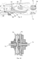
- Fig. 4 illustrates an enlarged view of the bearing structure.
- the bearing structure is configured with a front-end plate 40 and a rear-end plate 41.
- the front-end plate is formed with bearing front bolt holes 42 for receiving fixing bolts when enter front bolt holes 20 in the front section.
- the rear-end plate is provided with either external treaded studs or internal threads 21.
- the front-end plate 40 and the rear-end plate 41 are joined by the bearing section 43 forming in one combined unit both a radial and an axial bearing. This bearing section is sealed and therefore protected independent of the front section and the rear section of the vehicle.
- the drive pulley wheels 73 or the belt pulley wheels 70 are attached to freewheel, and the pedals may be free to drive the vehicle without rotating the electric motor.
- the combined manual transmission and power transmission solution illustrated in Figs. 7-8 provides a compact and very efficient means of allowing the driven axle wheels to spin with different velocity, while providing mechanical traction control aid on slippery surfaces.
- Fig. 8 further illustrates an electronic switch 87 arranged between the second intermediate chain wheel 84 and the crank chain wheel 85.
- the second chain further drives via a chain tension wheel 88.
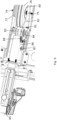
- Fig. 10 illustrates further details of the transmission structure connecting the powered drive and the manual drive to one or each of the at least two rear wheels.
- Fig. 12 illustrates details of the utility bed 15.
- the utility bed is designed to carry cargo for transportation, and it forms a load platform 120 for carrying items in one level over ground.
- a recessed forklift utility portion 121 is at a lower level than the platform and forms elongated tracks.
- the forklift utility portion allows access for a forklift to enter below items carried by the platform.
- the elongated tracks are parallelly disposed and extend in the lengthwise direction to allow loading or emptying of the utility bed from behind the vehicle.
- the tracks could also be sideways arranged.
- the load platform forms an intermediate section 122 between two outer sections 123.
- the intermediate and outer sections are separated by the forklift utility portion.
- the electric motor 16, the pulley wheels 73, the chain wheel 80, the intermediate chain wheels 81, 84 and the first chain 82 are located in the compartment formed underneath the intermediate section and the intermediate section and the sidewalls extending between the intermediate section 122 and the forklift utility portion 121 thereby protect the drive structure.
- the outer sections 123 of the load platform 120 comprises through holes 124. These are explained further relative to Fig. 13 and provides spacing for wheels of containers to be transported on the utility bed 15.
- Fig. 13 illustrates the vehicle with a container 130 loaded on the load platform and clearly illustrates the spacing for a forklift provided by the recessed forklift utility portion 121.
- the container wheels 131 are fixed on the container and used for rolling the container when it is not loaded onto the utility bed 15.
- the through holes 124 in the outer sections 123 of the load platform 120 allow the wheels 131 to extend through the outer section and thus the container to rest with its lower surface on the utility bed.
Landscapes
- Engineering & Computer Science (AREA)
- Mechanical Engineering (AREA)
- Chemical & Material Sciences (AREA)
- Combustion & Propulsion (AREA)
- Transportation (AREA)
- Automatic Cycles, And Cycles In General (AREA)
Claims (13)
- Véhicule utilitaire (1) comprenant une section arrière (2) et une section avant (3) disposée devant la section arrière dans une direction longitudinale, la section avant formant un siège (5), au moins une roue avant pouvant tourner autour d'un axe de roue (8), et une poignée de direction (7) reliée de manière fonctionnelle à la roue avant, la section arrière formant au moins deux roues arrière (13, 14), un entraînement alimenté en puissance comprenant un moteur (16), et un plateau utilitaire (15), dans lequel la section avant (3) est jointe à la section arrière (2) dans une structure de palier (4) fournissant une suspension combinée de palier radial et axial permettant la rotation de la section avant par rapport à la section arrière autour d'un axe de rotation (18) et permettant le transfert de la force axiale entre la section avant (3) et la section arrière (2), dans lequel la structure de palier (4) est fixée de manière amovible à la fois à la section avant et à la section arrière, caractérisé en ce que la structure de palier (4) est une unité scellée de manière permanente et pré-lubrifiée qui est étanche à la poussière et à l'eau.
- Véhicule utilitaire selon la revendication 1, dans lequel la structure de palier (4) est un palier fermé.
- Véhicule utilitaire selon l'une quelconque des revendications précédentes, dans lequel l'axe de rotation (18) est situé entre le siège (5) et l'axe de roue (8) dans une projection sur un plan vertical perpendiculaire à l'axe de rotation (18).
- Véhicule utilitaire selon la revendication 1, comprenant une entrée d'entraînement manuel (11) comprenant une structure de manivelle (11) reliée à au moins une des roues arrière par l'intermédiaire d'une transmission manuelle.
- Véhicule utilitaire selon la revendication 4, dans lequel la structure de manivelle (11) comprend un bras de manivelle fixé pour faire tourner un arbre de manivelle autour d'un axe de manivelle et définir un champ de rotor traversé par le bras de manivelle lors d'une rotation complète de l'arbre de manivelle, et dans lequel l'axe de rotation (18) coupe une projection du champ de rotor sur un plan central perpendiculaire à l'axe de manivelle.
- Véhicule utilitaire selon la revendication 5, dans lequel l'axe de manivelle est perpendiculaire à l'axe de rotation (18).
- Véhicule utilitaire selon l'une quelconque des revendications 4 à 6, dans lequel la transmission manuelle met en fonctionnement l'entraînement alimenté en puissance entre un état activé et un état non activé.
- Véhicule utilitaire selon l'une quelconque des revendications précédentes, comprenant une transmission de puissance reliant l'entraînement alimenté en puissance à chacune parmi l'au moins deux roues arrière (13, 14), la transmission de puissance comprenant :- une première roue de poulie à courroie (70) reliée à un premier arbre d'entraînement (71) par l'intermédiaire d'un premier accouplement, et- une seconde roue de poulie à courroie (70) reliée à un second arbre d'entraînement (71) par l'intermédiaire d'un second accouplement ;dans lequel le premier arbre d'entraînement (71) est relié à une première roue parmi l'au moins deux roues arrière (13), le second arbre d'entraînement (71) est relié à une seconde roue parmi l'au moins deux roues arrière (14).
- Véhicule utilitaire selon les revendications 4 et 8, dans lequel la transmission manuelle est reliée à la structure de manivelle (11) par une structure de roue à chaîne permettant une roue libre par rapport aux arbres d'entraînement (71).
- Véhicule utilitaire selon l'une quelconque des revendications précédentes, comprenant une structure d'amortissement (110) n'ayant pas d'effet ressort et agissant entre la première et la seconde section pour amortir le mouvement de la section avant (3) par rapport à la section arrière (2) autour de l'axe de rotation (18).
- Véhicule utilitaire selon la revendication 10, dans lequel la structure d'amortisseur (110) comprend au moins un premier et un second amortisseur séparé.
- Véhicule utilitaire selon l'une quelconque des revendications précédentes, le plateau utilitaire formant une plate-forme (120) pour transporter des articles et formant une partie utilitaire pour chariot élévateur (121) se trouvant à un niveau inférieur à la plate-forme (120) et permettant l'accès à un chariot élévateur pour entrer sous les articles transportés par la plate-forme.
- Véhicule utilitaire selon la revendication 12, dans lequel la partie utilitaire de chariot élévateur (121) définit au moins deux pistes allongées et disposées parallèlement s'étendant dans la direction longitudinale.
Priority Applications (2)
| Application Number | Priority Date | Filing Date | Title |
|---|---|---|---|
| EP21168573.0A EP4074585B1 (fr) | 2021-04-15 | 2021-04-15 | Véhicule utilitaire |
| ES21168573T ES3035666T3 (en) | 2021-04-15 | 2021-04-15 | A utility vehicle |
Applications Claiming Priority (1)
| Application Number | Priority Date | Filing Date | Title |
|---|---|---|---|
| EP21168573.0A EP4074585B1 (fr) | 2021-04-15 | 2021-04-15 | Véhicule utilitaire |
Publications (3)
| Publication Number | Publication Date |
|---|---|
| EP4074585A1 EP4074585A1 (fr) | 2022-10-19 |
| EP4074585C0 EP4074585C0 (fr) | 2025-07-02 |
| EP4074585B1 true EP4074585B1 (fr) | 2025-07-02 |
Family
ID=75539168
Family Applications (1)
| Application Number | Title | Priority Date | Filing Date |
|---|---|---|---|
| EP21168573.0A Active EP4074585B1 (fr) | 2021-04-15 | 2021-04-15 | Véhicule utilitaire |
Country Status (2)
| Country | Link |
|---|---|
| EP (1) | EP4074585B1 (fr) |
| ES (1) | ES3035666T3 (fr) |
Citations (2)
| Publication number | Priority date | Publication date | Assignee | Title |
|---|---|---|---|---|
| KR100758311B1 (ko) * | 2007-06-19 | 2007-09-12 | 이두원 | 후륜완충구를 갖는 삼륜자전거 |
| JP2019077287A (ja) * | 2017-10-23 | 2019-05-23 | 株式会社イケヤフォ−ミュラ | 小型車両 |
Family Cites Families (3)
| Publication number | Priority date | Publication date | Assignee | Title |
|---|---|---|---|---|
| JPH08142966A (ja) * | 1994-11-17 | 1996-06-04 | Yamaha Motor Co Ltd | パワーアシスト三輪自転車 |
| KR101197628B1 (ko) * | 2010-10-20 | 2012-11-07 | 구성득 | 삼륜 전기 자전거 |
| EP3205564B1 (fr) * | 2016-01-21 | 2019-06-19 | Herbert Weber | Vélo cargo |
-
2021
- 2021-04-15 EP EP21168573.0A patent/EP4074585B1/fr active Active
- 2021-04-15 ES ES21168573T patent/ES3035666T3/es active Active
Patent Citations (2)
| Publication number | Priority date | Publication date | Assignee | Title |
|---|---|---|---|---|
| KR100758311B1 (ko) * | 2007-06-19 | 2007-09-12 | 이두원 | 후륜완충구를 갖는 삼륜자전거 |
| JP2019077287A (ja) * | 2017-10-23 | 2019-05-23 | 株式会社イケヤフォ−ミュラ | 小型車両 |
Also Published As
| Publication number | Publication date |
|---|---|
| ES3035666T3 (en) | 2025-09-08 |
| EP4074585A1 (fr) | 2022-10-19 |
| EP4074585C0 (fr) | 2025-07-02 |
Similar Documents
| Publication | Publication Date | Title |
|---|---|---|
| US20200195090A1 (en) | Hub motor arrangement or vehicle with hub motor arrangement | |
| US9051019B2 (en) | Transport vehicle having a three-wheel chassis | |
| US4611684A (en) | Front-wheel drive motor vehicle | |
| US7610979B1 (en) | Reverse drive system for a three-wheeled vehicle | |
| US4682668A (en) | Go-cart | |
| US9162557B2 (en) | Drive unit for a vehicle wheel | |
| JP2002503174A (ja) | 単一または複軌道の電気モータ駆動車両用揺動腕動力ユニット | |
| JP7650084B2 (ja) | 車両動力補助駆動システム | |
| WO2005066015A1 (fr) | Bicyclette et differentiel pour bicyclette | |
| CN107848600B (zh) | 轮毂马达装置或具有轮毂马达装置的车辆 | |
| US5685385A (en) | Electrically driven cart | |
| US20110295452A1 (en) | Two wheeled vehicle with all wheel drive system | |
| US20100071983A1 (en) | Three wheel vehicle rear suspension | |
| EP1334023B1 (fr) | Vehicule a deux roues et a deux roues motrices | |
| US12344348B2 (en) | Electric vehicle with swing arm for independently articulating wheels | |
| US20100320023A1 (en) | Four wheel vehicle having a rotatable body section and method therefor | |
| WO2019162714A1 (fr) | Tricycle pour transport de passagers et de marchandises | |
| US20080115995A1 (en) | Anti-lock brake | |
| US9493200B2 (en) | Couplable drive unit and steering unit | |
| EP4074585B1 (fr) | Véhicule utilitaire | |
| JP7122683B2 (ja) | 電動3輪自転車 | |
| EP4074586A1 (fr) | Véhicule utilitaire | |
| EP4074588A1 (fr) | Véhicule utilitaire | |
| CN219668402U (zh) | 车辆 | |
| CN212861610U (zh) | 独立转向机构及采用该机构的货物运输车 |
Legal Events
| Date | Code | Title | Description |
|---|---|---|---|
| PUAI | Public reference made under article 153(3) epc to a published international application that has entered the european phase |
Free format text: ORIGINAL CODE: 0009012 |
|
| STAA | Information on the status of an ep patent application or granted ep patent |
Free format text: STATUS: THE APPLICATION HAS BEEN PUBLISHED |
|
| AK | Designated contracting states |
Kind code of ref document: A1 Designated state(s): AL AT BE BG CH CY CZ DE DK EE ES FI FR GB GR HR HU IE IS IT LI LT LU LV MC MK MT NL NO PL PT RO RS SE SI SK SM TR |
|
| STAA | Information on the status of an ep patent application or granted ep patent |
Free format text: STATUS: REQUEST FOR EXAMINATION WAS MADE |
|
| 17P | Request for examination filed |
Effective date: 20230419 |
|
| RBV | Designated contracting states (corrected) |
Designated state(s): AL AT BE BG CH CY CZ DE DK EE ES FI FR GB GR HR HU IE IS IT LI LT LU LV MC MK MT NL NO PL PT RO RS SE SI SK SM TR |
|
| STAA | Information on the status of an ep patent application or granted ep patent |
Free format text: STATUS: EXAMINATION IS IN PROGRESS |
|
| 17Q | First examination report despatched |
Effective date: 20230802 |
|
| GRAP | Despatch of communication of intention to grant a patent |
Free format text: ORIGINAL CODE: EPIDOSNIGR1 |
|
| STAA | Information on the status of an ep patent application or granted ep patent |
Free format text: STATUS: GRANT OF PATENT IS INTENDED |
|
| RIC1 | Information provided on ipc code assigned before grant |
Ipc: B62J 45/411 20200101ALN20250120BHEP Ipc: B62K 15/00 20060101ALN20250120BHEP Ipc: B62M 6/50 20100101ALI20250120BHEP Ipc: B62M 9/02 20060101ALI20250120BHEP Ipc: B62M 6/60 20100101ALI20250120BHEP Ipc: B62K 5/06 20060101ALI20250120BHEP Ipc: B62K 7/04 20060101ALI20250120BHEP Ipc: B62K 5/10 20130101AFI20250120BHEP |
|
| INTG | Intention to grant announced |
Effective date: 20250212 |
|
| GRAS | Grant fee paid |
Free format text: ORIGINAL CODE: EPIDOSNIGR3 |
|
| GRAA | (expected) grant |
Free format text: ORIGINAL CODE: 0009210 |
|
| STAA | Information on the status of an ep patent application or granted ep patent |
Free format text: STATUS: THE PATENT HAS BEEN GRANTED |
|
| AK | Designated contracting states |
Kind code of ref document: B1 Designated state(s): AL AT BE BG CH CY CZ DE DK EE ES FI FR GB GR HR HU IE IS IT LI LT LU LV MC MK MT NL NO PL PT RO RS SE SI SK SM TR |
|
| REG | Reference to a national code |
Ref country code: GB Ref legal event code: FG4D |
|
| REG | Reference to a national code |
Ref country code: CH Ref legal event code: EP |
|
| REG | Reference to a national code |
Ref country code: DE Ref legal event code: R096 Ref document number: 602021033174 Country of ref document: DE |
|
| REG | Reference to a national code |
Ref country code: IE Ref legal event code: FG4D |
|
| U01 | Request for unitary effect filed |
Effective date: 20250729 |
|
| U07 | Unitary effect registered |
Designated state(s): AT BE BG DE DK EE FI FR IT LT LU LV MT NL PT RO SE SI Effective date: 20250804 |
|
| REG | Reference to a national code |
Ref country code: ES Ref legal event code: FG2A Ref document number: 3035666 Country of ref document: ES Kind code of ref document: T3 Effective date: 20250908 |
|
| PG25 | Lapsed in a contracting state [announced via postgrant information from national office to epo] |
Ref country code: IS Free format text: LAPSE BECAUSE OF FAILURE TO SUBMIT A TRANSLATION OF THE DESCRIPTION OR TO PAY THE FEE WITHIN THE PRESCRIBED TIME-LIMIT Effective date: 20251102 |
|
| PG25 | Lapsed in a contracting state [announced via postgrant information from national office to epo] |
Ref country code: NO Free format text: LAPSE BECAUSE OF FAILURE TO SUBMIT A TRANSLATION OF THE DESCRIPTION OR TO PAY THE FEE WITHIN THE PRESCRIBED TIME-LIMIT Effective date: 20251002 |
|
| PG25 | Lapsed in a contracting state [announced via postgrant information from national office to epo] |
Ref country code: HR Free format text: LAPSE BECAUSE OF FAILURE TO SUBMIT A TRANSLATION OF THE DESCRIPTION OR TO PAY THE FEE WITHIN THE PRESCRIBED TIME-LIMIT Effective date: 20250702 |
|
| PG25 | Lapsed in a contracting state [announced via postgrant information from national office to epo] |
Ref country code: GR Free format text: LAPSE BECAUSE OF FAILURE TO SUBMIT A TRANSLATION OF THE DESCRIPTION OR TO PAY THE FEE WITHIN THE PRESCRIBED TIME-LIMIT Effective date: 20251003 |
|
| PG25 | Lapsed in a contracting state [announced via postgrant information from national office to epo] |
Ref country code: CZ Free format text: LAPSE BECAUSE OF FAILURE TO SUBMIT A TRANSLATION OF THE DESCRIPTION OR TO PAY THE FEE WITHIN THE PRESCRIBED TIME-LIMIT Effective date: 20250702 |
|
| PG25 | Lapsed in a contracting state [announced via postgrant information from national office to epo] |
Ref country code: PL Free format text: LAPSE BECAUSE OF FAILURE TO SUBMIT A TRANSLATION OF THE DESCRIPTION OR TO PAY THE FEE WITHIN THE PRESCRIBED TIME-LIMIT Effective date: 20250702 |
|
| PG25 | Lapsed in a contracting state [announced via postgrant information from national office to epo] |
Ref country code: RS Free format text: LAPSE BECAUSE OF FAILURE TO SUBMIT A TRANSLATION OF THE DESCRIPTION OR TO PAY THE FEE WITHIN THE PRESCRIBED TIME-LIMIT Effective date: 20251002 |
|
| PG25 | Lapsed in a contracting state [announced via postgrant information from national office to epo] |
Ref country code: SM Free format text: LAPSE BECAUSE OF FAILURE TO SUBMIT A TRANSLATION OF THE DESCRIPTION OR TO PAY THE FEE WITHIN THE PRESCRIBED TIME-LIMIT Effective date: 20250702 |
|
| PG25 | Lapsed in a contracting state [announced via postgrant information from national office to epo] |
Ref country code: SK Free format text: LAPSE BECAUSE OF FAILURE TO SUBMIT A TRANSLATION OF THE DESCRIPTION OR TO PAY THE FEE WITHIN THE PRESCRIBED TIME-LIMIT Effective date: 20250702 |