EP4074603A1 - Système de dégivrage, profil aérodynamique et aéronef comportant un tel système et procédé de dégivrage - Google Patents
Système de dégivrage, profil aérodynamique et aéronef comportant un tel système et procédé de dégivrage Download PDFInfo
- Publication number
- EP4074603A1 EP4074603A1 EP21168678.7A EP21168678A EP4074603A1 EP 4074603 A1 EP4074603 A1 EP 4074603A1 EP 21168678 A EP21168678 A EP 21168678A EP 4074603 A1 EP4074603 A1 EP 4074603A1
- Authority
- EP
- European Patent Office
- Prior art keywords
- heating
- leading edge
- edge portion
- predetermined breaking
- icing
- Prior art date
- Legal status (The legal status is an assumption and is not a legal conclusion. Google has not performed a legal analysis and makes no representation as to the accuracy of the status listed.)
- Granted
Links
Images



Classifications
-
- B—PERFORMING OPERATIONS; TRANSPORTING
- B64—AIRCRAFT; AVIATION; COSMONAUTICS
- B64D—EQUIPMENT FOR FITTING IN OR TO AIRCRAFT; FLIGHT SUITS; PARACHUTES; ARRANGEMENT OR MOUNTING OF POWER PLANTS OR PROPULSION TRANSMISSIONS IN AIRCRAFT
- B64D15/00—De-icing or preventing icing on exterior surfaces of aircraft
- B64D15/12—De-icing or preventing icing on exterior surfaces of aircraft by electric heating
- B64D15/14—De-icing or preventing icing on exterior surfaces of aircraft by electric heating controlled cyclically along length of surface
-
- B—PERFORMING OPERATIONS; TRANSPORTING
- B64—AIRCRAFT; AVIATION; COSMONAUTICS
- B64D—EQUIPMENT FOR FITTING IN OR TO AIRCRAFT; FLIGHT SUITS; PARACHUTES; ARRANGEMENT OR MOUNTING OF POWER PLANTS OR PROPULSION TRANSMISSIONS IN AIRCRAFT
- B64D15/00—De-icing or preventing icing on exterior surfaces of aircraft
-
- B—PERFORMING OPERATIONS; TRANSPORTING
- B64—AIRCRAFT; AVIATION; COSMONAUTICS
- B64D—EQUIPMENT FOR FITTING IN OR TO AIRCRAFT; FLIGHT SUITS; PARACHUTES; ARRANGEMENT OR MOUNTING OF POWER PLANTS OR PROPULSION TRANSMISSIONS IN AIRCRAFT
- B64D15/00—De-icing or preventing icing on exterior surfaces of aircraft
- B64D15/20—Means for detecting icing or initiating de-icing
- B64D15/22—Automatic initiation by icing detector
-
- B—PERFORMING OPERATIONS; TRANSPORTING
- B64—AIRCRAFT; AVIATION; COSMONAUTICS
- B64C—AEROPLANES; HELICOPTERS
- B64C2230/00—Boundary layer controls
- B64C2230/22—Boundary layer controls by using a surface having multiple apertures of relatively small openings other than slots
-
- B—PERFORMING OPERATIONS; TRANSPORTING
- B64—AIRCRAFT; AVIATION; COSMONAUTICS
- B64C—AEROPLANES; HELICOPTERS
- B64C2230/00—Boundary layer controls
- B64C2230/26—Boundary layer controls by using rib lets or hydrophobic surfaces
Definitions
- the invention relates to a de-icing system and a de-icing method.
- the invention further relates to an airfoil and an aircraft having the de-icing system.
- flight ice may accumulate on exposed portions of aircraft, such as leading edges of wings, horizontal and vertical tail planes, and high-lift devices, in particular if the aircraft, such as an airplane, flies through a cloud containing supercooled water droplets or if droplets impact on a supercooled airframe structure.
- ice protection system on commercial airliners mainly includes pneumatically operated systems employing bleed air heating or expanding inflatable rubber boots.
- the known systems are usually rather energy inefficient or are not suitable for new aircraft types that are envisioned as a more electrified aircraft system architecture.
- a commercial transport aircraft with a more electric system aircraft architecture was recently introduced to the market using an electro-thermal ice protection system. This system still uses continuous operation (so-called anti-icing mode) and rather heavy metallic heaters.
- microperforated leading edges such as a vertical tail plane leading edge.
- the microperforations improve laminarity of the aerodynamic boundary layer.
- the boundary layer of air can be sucked in through the microperforations.
- a negative pressure on the in-facing side of the leading edge allows the aerodynamic boundary layer from the out-facing surface to be controlled such that the result is an increase of laminar boundary length around the tail plane, reduction of drag, and improvement of fuel-efficiency.
- WO 2013 / 091 601 A2 and EP 1 644 450 B1 disclose superhydrophobic coatings to further reduce the adhesiveness of ice and simplify its removal.
- the invention provides a de-icing system configured for preventing the formation of and/or removing ice on a leading edge portion of an airfoil of an aircraft, the de-icing system comprising a heating foil that is adhesively bondable to the leading edge portion and that has a plurality of heating elements that are configured to be selectively energized for heating, an ice detecting device configured for detecting the presence of ice on the leading edge portion, and a control device configured for periodically and selectively energizing the heating elements based on the ice presence measured by the ice detecting device.
- the ice detecting device is integrated within the heating foil.
- the ice detecting device includes a temperature sensor, preferably a thermocouple.
- the heating elements include carbon based material or a carbon based thin film configured to produce heat when energized.
- the carbon based material or the carbon based thin film include any one of graphite, graphene and graphene related materials (GRM), or carbon nano tubes (CNT).
- control device is further configured to energize a first group of the heating elements such that a first linear heating pattern parallel to the leading edge portion is formed, in order to create a predetermined breaking line.
- control device is further configured to cyclically energize and de-energize the first group.
- control device is further configured to energize a third group of the heating elements such that a plurality of second linear heating pattern that are parallel to each other and orthogonal to the first heating line are formed.
- control device is further configured to cyclically energize and de-energize the third group.
- control device is further configured to energize a second group of the heating elements such that a square heating pattern arranged adjacent to a predetermined breaking line of the leading edge portion is formed.
- control device is further configured to energize a second group of the heating elements such that a U shaped heating pattern that has its opening facing towards a predetermined breaking line of the leading edge portion is formed.
- control device is further configured to energize a second group of the heating elements such that a T shaped heating pattern that has its stem adjacent to a predetermined breaking line of the leading edge portion is formed.
- control device is further configured to energize a second group of the heating elements such that a triangular heating pattern that has its base adjacent to a predetermined breaking line of the leading edge portion is formed.
- the heating triangle pattern is interposed between two consecutive third groups of heating elements.
- control device is further configured to energize a second group of the heating elements such that a V shaped heating pattern that has its tip facing away from the predetermined breaking line of the leading edge portion is formed.
- the heating V shaped pattern is interposed between two consecutive third groups of heating elements.
- control device is further configured to energize a second group of the heating elements such that a triangular heating pattern that has a tip arranged with a distance from and facing a predetermined breaking line of the leading edge portion is formed.
- control device is further configured to energize a second group of the heating elements such that a heating pattern having a pair of heating columns that extend orthogonal to a predetermined breaking line of the leading edge portion is formed, wherein in one of the columns extends further than the other column.
- control device is further configured to energize a second group of the heating elements such that a row heating pattern that extends parallel to a pre-determined breaking line of the leading edge portion is formed.
- control device is further configured to energize a second group of the heating elements such that a heating pattern of a plurality of heating rows that extend parallel to a predetermined breaking line of the leading edge portion, wherein the heating rows extend between the third group of heating elements.
- control device is further configured to cyclically energize and de-energize the second group.
- control device is configured to cyclically energize and de-energize the heating elements.
- control device is configured to progressively energize and de-energize the heating elements, preferably the second group, so as to transition between different heating patterns in such a manner the heating elements are energized progressively further away from the predetermined breaking line and/or along the predetermined breaking line.
- one or more heating patterns, a specific heating pattern or all heating patterns are repeated along the predetermined breaking line.
- the heating patterns on one side of the predetermined breaking line are offset along the predetermined breaking line relative to the heating patterns on the other side of the predetermined breaking line.
- the de-icing system further comprises a superhydrophobic coating that is applicable to the leading edge portion, wherein the superhydrophobic coating comprises a silicone nanofilament network.
- the invention provides an airfoil for an aircraft comprising a leading edge portion and a preferred de-icing system, wherein the heating foil is arranged at, preferably adhesively bonded to, an inner side of the leading edge portion, wherein the ice detecting device is arranged so as to allow for detection of ice on an outer side of the leading edge portion.
- the leading edge portion includes a plurality of microperforations configured for preserving laminarity of an aerodynamic boundary layer adjacent to the airfoil, wherein a superhydrophobic coating that has a silicone nanofilament network is arranged on an outer surface of the leading edge portion and/or a side wall portion of the microperforations.
- the airfoil is configured as a horizontal tail plane, a vertical tail plane, a high-lift device or a rotor blade.
- the invention provides an airfoil for an aircraft comprising a leading edge portion that includes a plurality of microperforations configured for preserving laminarity of an aerodynamic boundary layer adjacent to the airfoil, wherein a superhydrophobic coating that has a silicone nanofilament network is arranged on an outer surface of the leading edge portion and/or a side wall portion of the microperforations.
- the airfoil includes a preferred de-icing system, wherein the heating foil is arranged at, preferably adhesively bonded to, an inner side of the leading edge portion, wherein the ice detecting device is arranged so as to allow for detection of ice on an outer side of the leading edge portion.
- the airfoil is configured as a horizontal tail plane, a vertical tail plane, a wing or a high-lift device.
- the invention provides an aircraft comprising a preferred de-icing system and/or a preferred airfoil.
- the invention provides a de-icing method for de-icing a leading edge portion of an airfoil of an aircraft using a heating foil attached to the leading edge portion, the heat foil having a plurality of heating elements, the method comprising the steps of:
- the de-icing method further comprises the step of: c) energizing a third group of heating elements such that a plurality of second heating lines that are parallel to each other and orthogonal to the first heating line are formed.
- Standard heating systems e.g. bleed air or metallic heating wires
- bleed air or metallic heating wires enable anti-icing operations on e.g. the wing.
- the surface e.g. wing
- heating foils can exhibit a higher power density and a quicker response which enables operation in de-icing mode.
- de-icing mode ice may grow until a critical thickness is reached. Then, the heating foils are turned on and due to thermal shock, cracks are generated in the ice layer and the ice is shed off. Turning the heating foil on and off can be done automatically by using ice detection sensors and thermocouples preferably implemented into the heating foil.
- De-icing mode also prevents run back ice contrary to the anti-icing mode.
- the constant heating forms liquid water which may freeze again behind the heated surface.
- a commercially available (printed) heating foil foil + heatable ink + foil
- a high power density e.g. > 5 W/cm 2
- the thin film heaters are based on graphite, carbon nanotubes (CNT) or graphene and related materials (GRM), which can be much lighter and more energy efficient than conventional metallic heaters.
- the heaters are cyclically heated.
- This technology can also be used for microperforated surfaces used for hybrid laminar flow control (HLFC) systems.
- the heating foil is preferably attached to the backside of the micro-perforated skin (pore diameter of approx. 50 ⁇ m) with a corresponding perforation.
- Another preferred use case is the implementation of a heating system on top of drones' rotor blades e.g. with a battery as a power supply attached to the middle section of the rotor blade holder.
- a superhydrophobic coating which is preferably arranged not only on the outer surface but also within the microperforations, allows both for air to pass through the microperforations and from contaminants, in particular ice, from getting stuck over and inside of the microperforations.
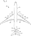
- the aircraft 10 includes a fuselage 12.
- a pair of wings 14 are attached to the fuselage 12, in a manner known per se.
- the wing 14 may include one or more high-lift devices 16.
- the aircraft 10 further comprises a horizontal tail plane 18 and a vertical tail plane 20.
- the wing 14, the high-lift devices 16, and the horizontal and vertical tail plane 18, 20 are examples of an airfoil 22.
- the airfoil 22 may comprise a separate leading edge member or an integrated leading edge member, collectively described herein as a leading edge portion 24.
- the aircraft 10 includes a de-icing system 26.
- the de-icing system 26 comprises a heating foil 28.
- the heating foil 28 is arranged on an inward facing side of the leading edge portion 24.
- the de-icing system 26 further comprises an ice detecting device 30 that is preferably integrated into the heating foil 28.
- the ice detecting device 30 includes a thermocouple 32 that is arranged on the inward facing side of the leading edge portion 24.
- the ice detecting device 30 may alternatively or additionally include an optical sensor with or without optical fibers, an acoustic sensor for detecting surface acoustic waves, and/or a pressure sensor.
- the de-icing system 26 further comprises a control device 34.
- the control device 34 is connected to the heating foil 28 and the ice detecting device 30 in order to control a de-icing process.
- the heating foil 28 includes a plurality of heating elements 36.
- the heating elements 36 are preferably of a carbon-based material, such as graphite, graphene and related materials (GRM) or carbon nanotubes (CNT).
- GEM graphite, graphene and related materials
- CNT carbon nanotubes
- the heating elements 36 are configured as a thin film and preferably sandwiched in between electrically isolating thin foils.
- the heating foil 28 is configured such that individual heating elements 36 may be energized by the control device 34 depending on the detection of ice by the ice detecting device 30.
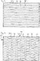
- the heating elements 36 may be configured as heating stripes 38 that are arranged substantially in parallel to the leading edge portion 24.
- the heating elements 36 may be configured as heating rectangles 40.
- the heating elements 36 are arranged in a plurality of heating rows 42 and heating columns 44.
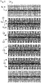
- a first group 46 of the heating elements 36 is energized.
- the first group 46 forms a first linear heating pattern 48.
- the first linear heating pattern 48 is parallel to the leading edge portion 24.
- the first linear heating pattern 48 generates a pre-determined breaking line for ice that has accumulated on the airfoil 22.
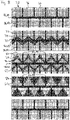
- the control device 34 energizes a second group 50 of the heating elements 36.
- the second group 50 is configured as a square heating pattern 52.
- the square heating pattern 52 is arranged adjacent to the first group 46.
- the square heating pattern 52 is repeated multiple times along the extension of the first group 46.
- the square heating patterns 52 above the first linear heating pattern 48 are offset along the direction of the leading edge portion 24 relative to the square heating patterns 52 below the first linear heating pattern 48.
- the control device 34 further energizes heating elements such that the energized heating elements are progressively further away from the first group 46.
- the second group 50 is energized such that a U shaped heating pattern 54 is generated.
- the opening of the U is facing the first group 46.
- leg portions 56 of the U shaped heating pattern 54 are arranged adjacent to the first group 46.
- the U shaped heating patterns 54 are offset along the extension of the first linear heating pattern 48 and depending on whether the U shaped heating pattern 54 is above or below the first linear heating pattern 48.
- the U shaped heating patterns 54 are arranged such that a meandering heating pattern 58 is generated.
- the second group 50 is energized by the control device 34 such that a T shaped heating pattern 60 is generated.
- a stem portion 62 of the T shaped heating pattern 60 is arranged adjacent to the first linear heating pattern 48.
- the stem portion 62 extends orthogonally relative to the first linear heating pattern 48.
- a plurality of T shaped heating patterns 60 is offset along the first linear heating pattern 48.
- the T shaped heating pattern 60 are arranged such that each stem portion 62 is adjacent to the first linear heating pattern 48 and a crossbar portion 64 connects the respective stem portions 62 on one side of the first linear heating pattern 48.
- all heating elements 36 with the exception of a rectangular de-energized portion 66 are energized.
- the second group 50 is de-energized, while the first group 46 is kept energized.
- de-icing cycle is identical to the previously described de-icing cycle.
- the second group 50 is configured as a pair of heating columns 68.
- the heating columns 68 extend orthogonal to the first group 46.
- One of the heating columns 68 is shorter than the other one of the heating columns 68.
- the heating columns 68 are energized and de-energized such that the heating columns 68 seem to progress along the direction of the leading edge portion 24 from left to right. It should be noted that a progression in the opposite direction is also possible.
- the first group 46 is energized in the same way as in the previously described embodiments.
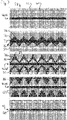
- the second group 50 is energized by the control device 34 such that a triangular heating pattern 70 is generated.
- the triangular heating pattern 70 is preferably configured as an isosceles triangle.
- the triangular heating pattern 70 is arranged such that a base portion 72 is arranged adjacent to the first group 46, whereas a tip portion 74 is facing away from the first group 46.
- the triangular heating pattern 70 are again offset along the direction of the first linear heating pattern 48 and preferably have a different offset depending on whether the triangular heating pattern 70 is above or below the first linear heating pattern 48.
- the triangular heating pattern 70 are preferably arranged such that a meandering heating pattern 76 is created.
- control device 34 energizes the second group 50 such that a V shaped heating pattern 78 is created.
- leg portions 80 of the V shaped heating pattern 78 are arranged adjacent to the first linear heating pattern 48.
- a tip portion 82 of the V shaped heating pattern 78 is facing away from the first linear heating pattern 48.
- the second group 50 is again energized in a triangular heating pattern 84, however, the base portion 72 and the tip portion 74 are flipped.
- control device 34 energized the heating elements 36 such that the heating elements 36 are progressively energized further away from the first linear heating pattern 48, whereby none of the heating elements 36 is energized twice during progression of the de-icing cycle.
- FIG. 8 another embodiment of a de-icing cycle is depicted, which is a variant of the de-icing cycle according to Fig. 7 .
- a third group 86 of heating elements is energized.
- the third group 86 creates a second linear heating pattern 88 that extends orthogonally from the first linear heating pattern 48.
- the first group 46 and third group 86 are permanently energized.
- the second group 50 is energized such that the respective patterns are formed between two neighboring second linear heating patterns 88.
- the third group 86 is arranged such that it forms a symmetry line of the triangular heating pattern 84.
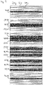
- the heating foil 28 is configured as having the heating stripe 38.
- the first group 46 again forms a first linear heating pattern 48 that extends substantially in parallel to the leading edge portion 24.
- the second group 50 is energized so as to form a row heating pattern 90 that extends parallel to the first linear heating pattern 48.
- the control device 34 is configured such that the heating stripes 38 are energized progressively away from the first linear heating pattern 48. In other words, the patterns are created such that the heat seems to move away from the first linear heating pattern 48.
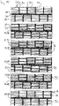
- the heating foil 28 in addition to the heating stripes 38 further comprises of orthogonal heating stripes 92 that orthogonally extend from the first group 46.
- the orthogonal heating stripes 92 form the third group 86 in this embodiment.
- the second group 50 is energized by the control device 34 such that the heating stripes 38 are energized progressively moving outward from the first group 46, where in the second group 50 is arranged between two neighboring orthogonal heating stripes 92.
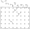
- the leading edge portion 24 includes microperforations 94.
- the microperforations 94 are part of a hybrid laminar flow control (HLFC) system.
- HLFC hybrid laminar flow control
- the leading edge portion 24 includes a superhydrophobic coating 98.
- the superhydrophobic coating 98 is only arranged on the skin of the leading edge portion 24.
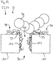
- a cross section through the leading edge portion 24 is depicted.
- the superhydrophobic coating 98 is not only arranged on the skin of the leading edge portion but also on a sidewall 102 of the microperforations 94. It should be noted that in this embodiment, a flow channel 104 is kept free of the superhydrophobic coating 98.
- a further embodiment of the leading edge portion 24 that is similar to the embodiment depicted in Fig. 12 is depicted.
- the superhydrophobic coating 98 is arranged on the skin 100, the sidewall 102, and within the entire volume of the microperforation 94.
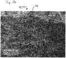
- the superhydrophobic coating 98 is sufficiently porous so as to not impede the function of the microperforations 94 in the HLFC system (see microscopic image depicted in Fig. 14 ).
- Silicone nanofilament (SNF) networks 99 grown on surfaces have been shown to have water-repelling properties. When the SNF networks 99 are fluorinated, they also show oil-repelling properties.
- the superhydrophobic coating 98 includes a silicone nanofilament network 99, which has in and of itself water-repelling properties.
- the superhydrophobic coating 98 may also be configured as a superoleophobic coating, if the silicone nanofilament networks are fluorinated and thus additionally exhibit oil-repelling properties.
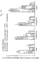
- Fig. 15 shows the interfacial adhesion strength of four different types of impact ice (ice formed by impacting supercooled water droplets in-flight) on three different surfaces.
- the first surface is the native oxide layer on a metal alloy whose primary component is titanium (Ti6AI4V).
- the second surface is that described in WO 2013 / 091 601A2 , specifically, the same alloy anodized such that the oxide layer grew in the shape of nanotubes, and which was subsequently fluorinated using a commercial perfluoropolyether solution.
- the last surface is the same as the second, except instead of fluorinating it using the commercial solution, SNFs 99 were grown on the nanotubes and subsequently fluorinated using the method described below.
- fluorinated SNFs 99 and the commercially fluorinated nanotubes showed lower ice adhesion strength than the "bare" native oxide surface.
- the experiments show that fluorinated SNF networks 99 in general also exhibit ice-phobic properties and are durable enough to endure several icing/de-icing cycles.
- the silicone nanofilaments cover the surface of the micropores but do not bridge the diameter ( Fig. 12 ). Due to the small pore size and the amphiphobicity of the fluorinated silicone nanofilament network, droplets of water and oil greater than the micropore diameter are completely repelled, while smaller droplets are hindered in their passage through the microperforations.
- the sidewalls 102 are coated, so the effective diameter accessible to a droplet is slightly decreased; from a probabilistic point of view, the coating on the rims and on the "entrance" of the walls reduces the number of configurations (in terms of impact point and trajectory) that can result in a droplet going through the hole.
- the silicone nanofilament network 99 bridges the entire diameter of the micropores ( Fig. 13 ). Due to the porous nature of the nanofilament network, gases such as air can easily pass through the pores, thus retaining the intended functionality of the permeable drag reduction device.
- the network of SNFs effectively blocks any contaminants of passing through the pores of the micro-perforated plate; liquid contaminants simply bounce off.
- the method consists of growing superhydrophobic Silicone Nanofilaments (SNFs) on the surface of the microperforated airfoil 22 through a gas phase silanization process known in the art.
- SNFs superhydrophobic Silicone Nanofilaments
- SNFs cover the micro-perforation walls and fill them in the radial direction, creating a porous structure with spacings one or two orders of magnitude lower than the micro-perforation diameter.
- a subsequent fluorination makes the SNFs oleophobic or superoleophobic and therefore reduces the adhesion that both liquid and particulate contaminants have to the surface.
- the combined silanization and fluorination treatments reduce the adhesion of ice to the surface.
- Typical airfoils such as the VTP comprise a metal alloy containing primarily Ti, and possibly containing additional elements such as V, Fe, Sn, Ni, Nb, Mo, Zr, Y, Hf, Ta, Ce, Tb , Nd, Gd, Dy, Ho and Er and/or additionally at least one further element selected from the group comprising Zn, Mn, Ag, Li, Cu, Si, Al or Ca.
- the metallic plate is anodized in order to produce a nanoporous layer comprising nanotubes including titanium dioxide using a process described in WO 2013 / 091 601 A2 .
- the resulting nanotubes have diameters in the range of 30 nm to 600 nm.
- microperforated airfoils Prior to silanization, microperforated airfoils are pre-treated with an alkaline solution which may contain surface active compounds.
- an alkaline solution which may contain surface active compounds.
- One example of such treatment is sonication for 15 minutes in a 10%v/v aqueous solution of Deconex 11 universal (by Borer Chemie AG), after which samples are rinsed with deionized water and dried with N 2 gas flow.
- the process employs a silanizing mixture comprised of at least one component of formula I and at least one component of formula II:
- X 1 and X 2 are hydrolysable groups, where X 1 is a halogen, such as chlorine or fluorine, and X 2 is an alkoxy group.
- the micro-perforations walls are completely covered with a layer of SNFs with diameter in the range 50 nm - 200 nm.
- the so-obtained porous coating has a thickness in the order of micrometre to tens of micrometres, which can partly or completely fill the micro-perforations in the radial direction.
- This gas phase process is particularly suited to coat surfaces with complex shapes at the sub-millimetre range, such as the airfoil microperforations 94, when compared to conventional liquid- or spray-based processes. Moreover, scale-up of this process to coat large (1 m 2 ) substrates has been demonstrated ( Artus, G. and Seeger, S. (2012). Ind. Eng. Chem. Res., 51, 2631 ).
- Fluorination can be carried out either as a solvent phase or vapour phase process, as described in the art ( Zimmermann, J. et al. (2008). Soft Matter, 4(3), 450. doi:10.1039/b717734h ; Bhushan, B. et al. (2006). J. Vac. Sci. Technol. A, 24(4), 1197 ).
- R c Si(X 3 ) 3 where R c is a perfluorinated or polyfluorinated alkyl chain C (1-24) , X 3 is a hydrolysable group, such a as a halogen or alkoxy group.
- This process introduces fluorine-containing groups that are covalently linked to the surface. As such, it is superior in quality and stability to conventional treatments with perfluoropolyether (PFPE) compounds that are instead only bound to the surface through weak interactions.
- PFPE perfluoropolyether
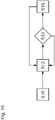
- FIG. 16 an embodiment of a de-icing method is described in more detail.
- the de-icing method includes a sensing step S10.
- the ice detecting device 30 detects, whether there is ice formation on the airfoil 22.
- the de-icing method further includes a measuring step S12.
- the measuring step S12 is executed after the sensing step S10.
- the control device 34 based on the data of the detecting device 30 determines the intensity of ice formation, e.g. as thickness increase per time unit in arbitrary units.
- the de-icing method further includes a comparing step S14.
- the comparing step S14 is executed after the measuring step S12.
- the intensity of ice formation that was determined in the measuring step S12 is compared with a predetermined threshold of an acceptable ice formation intensity.
- the de-icing method is continued in the measuring step S12.
- the de-icing method is continued in a de-icing step S16.
- the heating foil 28 is energized by the control device 34 such that any of the previously described heating patterns is generated or any of the previously described de-icing cycles is performed.
- the de-icing system (26) comprises a thin film heating foil (28) that is adhesively bonded to the leading edge portion (24).
- the heating foil (28) comprises a plurality of heating elements (36).
- an ice detecting device (30) is provided, which is able to detect the presence of ice on the leading edge portion (24) by optical, acoustical or thermal means.
- the de-icing system (26) has a control device (34), which is configured for periodically and selectively energizing the heating elements (36).
- a silicone nanofilament network (SNF) is added as a superhydrophobic coating (98) on a microperforated skin (100) and within the microperforations (94).
Landscapes
- Engineering & Computer Science (AREA)
- Aviation & Aerospace Engineering (AREA)
- Control Of Resistance Heating (AREA)
Priority Applications (1)
| Application Number | Priority Date | Filing Date | Title |
|---|---|---|---|
| EP21168678.7A EP4074603B1 (fr) | 2021-04-15 | 2021-04-15 | Système de dégivrage, profil aérodynamique et aéronef comportant un tel système et procédé de dégivrage |
Applications Claiming Priority (1)
| Application Number | Priority Date | Filing Date | Title |
|---|---|---|---|
| EP21168678.7A EP4074603B1 (fr) | 2021-04-15 | 2021-04-15 | Système de dégivrage, profil aérodynamique et aéronef comportant un tel système et procédé de dégivrage |
Publications (2)
| Publication Number | Publication Date |
|---|---|
| EP4074603A1 true EP4074603A1 (fr) | 2022-10-19 |
| EP4074603B1 EP4074603B1 (fr) | 2025-07-23 |
Family
ID=75539235
Family Applications (1)
| Application Number | Title | Priority Date | Filing Date |
|---|---|---|---|
| EP21168678.7A Active EP4074603B1 (fr) | 2021-04-15 | 2021-04-15 | Système de dégivrage, profil aérodynamique et aéronef comportant un tel système et procédé de dégivrage |
Country Status (1)
| Country | Link |
|---|---|
| EP (1) | EP4074603B1 (fr) |
Cited By (1)
| Publication number | Priority date | Publication date | Assignee | Title |
|---|---|---|---|---|
| WO2025201641A1 (fr) | 2024-03-27 | 2025-10-02 | Aeomiq Gmbh | Élément chauffant pour un système de protection contre la glace ; pièces équipées de celui-ci et procédé de fonctionnement |
Citations (11)
| Publication number | Priority date | Publication date | Assignee | Title |
|---|---|---|---|---|
| WO2011087412A1 (fr) * | 2010-01-14 | 2011-07-21 | Saab Ab | Système de dégivrage/antigivrage multifonctionnel |
| WO2013091601A2 (fr) | 2011-12-22 | 2013-06-27 | Eads Deutschland Gmbh | Surfaces autonettoyantes et superhydrophobes à base de nanotubes en tio2 |
| US8864082B2 (en) | 2009-05-20 | 2014-10-21 | Airbus Operations Gmbh | Device for reducing the aerodynamic drag of a leading surface of an aircraft |
| EP1644450B1 (fr) | 2003-06-23 | 2015-08-19 | University Of Zurich | Revêtement superhydrophobe |
| US9193443B2 (en) | 2010-09-02 | 2015-11-24 | Airbus Operations Gmbh | Air sucking vehicle tail section component or wing section component, method for producing an air sucking vehicle tail section component and a wing section component and a vehicle, especially an aircraft, with an air sucking vehicle tail section component or wing section component |
| EP3012187A1 (fr) * | 2014-10-23 | 2016-04-27 | The Boeing Company | Surfaces superhydrophobes activement contrôlées |
| CN108327913A (zh) * | 2017-12-29 | 2018-07-27 | 西北工业大学 | 一种基于超疏水电热蒙皮的防除冰控制方法 |
| US20180215476A1 (en) * | 2017-01-31 | 2018-08-02 | Anaya | Carbon nanotube anti-icing and de-icing means for aircraft |
| EP3450320A1 (fr) * | 2017-09-01 | 2019-03-06 | Bell Helicopter Textron Inc. | Système de protection contre le givre d'une pale de rotor personnalisé |
| EP3473595A1 (fr) * | 2017-10-20 | 2019-04-24 | Goodrich Corporation | Microperforations pour chauffages cnt |
| US20190248501A1 (en) * | 2018-02-15 | 2019-08-15 | Booz Allen Hamilton Inc. | Ice formation detection and removal system for an aerial vehicle and method |
Family Cites Families (2)
| Publication number | Priority date | Publication date | Assignee | Title |
|---|---|---|---|---|
| EP1873060B1 (fr) * | 2006-06-26 | 2010-04-07 | Honeywell International Inc. | Système hybride de dégivrage électrique et un procédé avec un mode d'économie d'énergie |
| JP4865644B2 (ja) * | 2007-06-25 | 2012-02-01 | セイコープレシジョン株式会社 | アクチュエータ及びコイル枠 |
-
2021
- 2021-04-15 EP EP21168678.7A patent/EP4074603B1/fr active Active
Patent Citations (11)
| Publication number | Priority date | Publication date | Assignee | Title |
|---|---|---|---|---|
| EP1644450B1 (fr) | 2003-06-23 | 2015-08-19 | University Of Zurich | Revêtement superhydrophobe |
| US8864082B2 (en) | 2009-05-20 | 2014-10-21 | Airbus Operations Gmbh | Device for reducing the aerodynamic drag of a leading surface of an aircraft |
| WO2011087412A1 (fr) * | 2010-01-14 | 2011-07-21 | Saab Ab | Système de dégivrage/antigivrage multifonctionnel |
| US9193443B2 (en) | 2010-09-02 | 2015-11-24 | Airbus Operations Gmbh | Air sucking vehicle tail section component or wing section component, method for producing an air sucking vehicle tail section component and a wing section component and a vehicle, especially an aircraft, with an air sucking vehicle tail section component or wing section component |
| WO2013091601A2 (fr) | 2011-12-22 | 2013-06-27 | Eads Deutschland Gmbh | Surfaces autonettoyantes et superhydrophobes à base de nanotubes en tio2 |
| EP3012187A1 (fr) * | 2014-10-23 | 2016-04-27 | The Boeing Company | Surfaces superhydrophobes activement contrôlées |
| US20180215476A1 (en) * | 2017-01-31 | 2018-08-02 | Anaya | Carbon nanotube anti-icing and de-icing means for aircraft |
| EP3450320A1 (fr) * | 2017-09-01 | 2019-03-06 | Bell Helicopter Textron Inc. | Système de protection contre le givre d'une pale de rotor personnalisé |
| EP3473595A1 (fr) * | 2017-10-20 | 2019-04-24 | Goodrich Corporation | Microperforations pour chauffages cnt |
| CN108327913A (zh) * | 2017-12-29 | 2018-07-27 | 西北工业大学 | 一种基于超疏水电热蒙皮的防除冰控制方法 |
| US20190248501A1 (en) * | 2018-02-15 | 2019-08-15 | Booz Allen Hamilton Inc. | Ice formation detection and removal system for an aerial vehicle and method |
Non-Patent Citations (4)
| Title |
|---|
| ARTUS, G.SEEGER, S., IND. ENG. CHEM. RES., vol. 51, 2012, pages 2631 |
| BHUSHAN, B. ET AL., J. VAC. SCI. TECHNO!. A, vol. 24, no. 4, 2006, pages 1197 |
| LAROCHE ET AL., SILICONE NANOFILAMENTS GROWN ON AIRCRAFT ALLOYS FOR LOW ICE ADHESION |
| ZIMMERMANN, J. ET AL., SOFT MATTER, vol. 4, no. 3, 2008, pages 450 |
Cited By (1)
| Publication number | Priority date | Publication date | Assignee | Title |
|---|---|---|---|---|
| WO2025201641A1 (fr) | 2024-03-27 | 2025-10-02 | Aeomiq Gmbh | Élément chauffant pour un système de protection contre la glace ; pièces équipées de celui-ci et procédé de fonctionnement |
Also Published As
| Publication number | Publication date |
|---|---|
| EP4074603B1 (fr) | 2025-07-23 |
Similar Documents
| Publication | Publication Date | Title |
|---|---|---|
| EP3012187B1 (fr) | Surfaces superhydrophobes activement contrôlées | |
| CA2575197C (fr) | Materiau super-hydrophobe, nanostructure, composite | |
| US7150904B2 (en) | Composite, ordered material having sharp surface features | |
| US10442540B2 (en) | Device and method for deicing and/or preventing ice formation and profile element and aircraft having such a device | |
| JP6466185B2 (ja) | 受動除氷のためのシステムおよび方法 | |
| US20090210103A1 (en) | Controlling aircraft aerial movements, defeating icing on aircraft surfaces, aiding decontamination, and damping turbulence effects on aircraft by the method of micro-perforated airfoil coordinated precision flow management | |
| EP2370316B1 (fr) | Systeme et procede de reduction de la force visqueuse entre un fluide et une surface | |
| JP2010234989A (ja) | 着氷防止構造を有する翼構造体 | |
| EP4074603B1 (fr) | Système de dégivrage, profil aérodynamique et aéronef comportant un tel système et procédé de dégivrage | |
| Hu et al. | Comparative study of using superhydrophobic and icephobic surface coatings for aircraft icing mitigation | |
| Han et al. | An experimental investigation to assess the effectiveness of various anti-icing coatings for UAV propeller icing mitigation | |
| Belaud et al. | Development of nanostructured icephobic aluminium oxide surfaces for aeronautic applications | |
| Strobl et al. | Development of a hybrid ice protection system based on nanostructured hydrophobic surfaces | |
| CN112935571B (zh) | 一种防冰功能性结构及其制备方法和应用 | |
| Dhulipalla et al. | An experimental study on aerodynamic performance degradation of a drone propeller due to rainfall | |
| US12091160B2 (en) | Actively controlled surfaces | |
| Hu et al. | An experimental study on ice accretion and anti-/de-icing of a pitot tube | |
| Zhang et al. | Perspective Chapter: Challenges in the Durability of Superhydrophobic Coatings Pertinent to Unmanned Aerial Vehicle (UAV) Icing Mitigation | |
| Saeed et al. | Hybrid airfoil design method to simulate full-scale ice accretion throughout a given a range | |
| Keley | Super–Hydrophobic Surfaces Based On Fluorinated Carbon And Its Application On Avoiding Ice–Accretion | |
| Mora et al. | Could superhydrophobic surfaces be a realistic solution for running-wet areas? | |
| Muhammed et al. | Experimental study of superhydrophobic coating effects on dynamic ice accretion ice accretion process along S-1223 airfoil | |
| EP3916135A1 (fr) | Procédé de modification d'une surface métallique, telle qu'une partie de bord d'attaque d'une surface portante | |
| JP2016028953A (ja) | 翼構造体、航空機の翼及び風力タービンブレード | |
| Guo et al. | Review of Surface Dielectric Barrier Discharge in Anti-icing and De-icing for Aircraft |
Legal Events
| Date | Code | Title | Description |
|---|---|---|---|
| PUAI | Public reference made under article 153(3) epc to a published international application that has entered the european phase |
Free format text: ORIGINAL CODE: 0009012 |
|
| STAA | Information on the status of an ep patent application or granted ep patent |
Free format text: STATUS: THE APPLICATION HAS BEEN PUBLISHED |
|
| AK | Designated contracting states |
Kind code of ref document: A1 Designated state(s): AL AT BE BG CH CY CZ DE DK EE ES FI FR GB GR HR HU IE IS IT LI LT LU LV MC MK MT NL NO PL PT RO RS SE SI SK SM TR |
|
| STAA | Information on the status of an ep patent application or granted ep patent |
Free format text: STATUS: REQUEST FOR EXAMINATION WAS MADE |
|
| 17P | Request for examination filed |
Effective date: 20230419 |
|
| RBV | Designated contracting states (corrected) |
Designated state(s): AL AT BE BG CH CY CZ DE DK EE ES FI FR GB GR HR HU IE IS IT LI LT LU LV MC MK MT NL NO PL PT RO RS SE SI SK SM TR |
|
| STAA | Information on the status of an ep patent application or granted ep patent |
Free format text: STATUS: EXAMINATION IS IN PROGRESS |
|
| 17Q | First examination report despatched |
Effective date: 20231222 |
|
| GRAP | Despatch of communication of intention to grant a patent |
Free format text: ORIGINAL CODE: EPIDOSNIGR1 |
|
| STAA | Information on the status of an ep patent application or granted ep patent |
Free format text: STATUS: GRANT OF PATENT IS INTENDED |
|
| INTG | Intention to grant announced |
Effective date: 20250217 |
|
| GRAS | Grant fee paid |
Free format text: ORIGINAL CODE: EPIDOSNIGR3 |
|
| GRAA | (expected) grant |
Free format text: ORIGINAL CODE: 0009210 |
|
| STAA | Information on the status of an ep patent application or granted ep patent |
Free format text: STATUS: THE PATENT HAS BEEN GRANTED |
|
| AK | Designated contracting states |
Kind code of ref document: B1 Designated state(s): AL AT BE BG CH CY CZ DE DK EE ES FI FR GB GR HR HU IE IS IT LI LT LU LV MC MK MT NL NO PL PT RO RS SE SI SK SM TR |
|
| REG | Reference to a national code |
Ref country code: GB Ref legal event code: FG4D |
|
| REG | Reference to a national code |
Ref country code: CH Ref legal event code: EP |
|
| REG | Reference to a national code |
Ref country code: DE Ref legal event code: R081 Ref document number: 602021034468 Country of ref document: DE Owner name: AIRBUS DEFENCE AND SPACE GMBH, DE Free format text: FORMER OWNER: ANMELDERANGABEN UNKLAR / UNVOLLSTAENDIG, 80297 MUENCHEN, DE Ref country code: DE Ref legal event code: R081 Ref document number: 602021034468 Country of ref document: DE Owner name: AIRBUS OPERATIONS GMBH, DE Free format text: FORMER OWNER: ANMELDERANGABEN UNKLAR / UNVOLLSTAENDIG, 80297 MUENCHEN, DE Ref country code: DE Ref legal event code: R081 Ref document number: 602021034468 Country of ref document: DE Owner name: UNIVERSITY OF ZUERICH, CH Free format text: FORMER OWNER: ANMELDERANGABEN UNKLAR / UNVOLLSTAENDIG, 80297 MUENCHEN, DE |
|
| REG | Reference to a national code |
Ref country code: IE Ref legal event code: FG4D |
|
| REG | Reference to a national code |
Ref country code: DE Ref legal event code: R096 Ref document number: 602021034468 Country of ref document: DE |
|
| REG | Reference to a national code |
Ref country code: DE Ref legal event code: R081 Ref document number: 602021034468 Country of ref document: DE Owner name: AIRBUS DEFENCE AND SPACE GMBH, DE Free format text: FORMER OWNERS: AIRBUS DEFENCE AND SPACE GMBH, 85521 OTTOBRUNN, DE; AIRBUS OPERATIONS GMBH, 21129 HAMBURG, DE; UNIVERSITY OF ZUERICH, ZUERICH, CH Ref country code: DE Ref legal event code: R081 Ref document number: 602021034468 Country of ref document: DE Owner name: AIRBUS OPERATIONS GMBH, DE Free format text: FORMER OWNERS: AIRBUS DEFENCE AND SPACE GMBH, 85521 OTTOBRUNN, DE; AIRBUS OPERATIONS GMBH, 21129 HAMBURG, DE; UNIVERSITY OF ZUERICH, ZUERICH, CH Ref country code: DE Ref legal event code: R081 Ref document number: 602021034468 Country of ref document: DE Owner name: UNIVERSITY OF ZUERICH, CH Free format text: FORMER OWNERS: AIRBUS DEFENCE AND SPACE GMBH, 85521 OTTOBRUNN, DE; AIRBUS OPERATIONS GMBH, 21129 HAMBURG, DE; UNIVERSITY OF ZUERICH, ZUERICH, CH |
|
| REG | Reference to a national code |
Ref country code: NL Ref legal event code: MP Effective date: 20250723 |
|
| PG25 | Lapsed in a contracting state [announced via postgrant information from national office to epo] |
Ref country code: PT Free format text: LAPSE BECAUSE OF FAILURE TO SUBMIT A TRANSLATION OF THE DESCRIPTION OR TO PAY THE FEE WITHIN THE PRESCRIBED TIME-LIMIT Effective date: 20251124 |
|
| PG25 | Lapsed in a contracting state [announced via postgrant information from national office to epo] |
Ref country code: NL Free format text: LAPSE BECAUSE OF FAILURE TO SUBMIT A TRANSLATION OF THE DESCRIPTION OR TO PAY THE FEE WITHIN THE PRESCRIBED TIME-LIMIT Effective date: 20250723 |
|
| REG | Reference to a national code |
Ref country code: AT Ref legal event code: MK05 Ref document number: 1816207 Country of ref document: AT Kind code of ref document: T Effective date: 20250723 |
|
| PG25 | Lapsed in a contracting state [announced via postgrant information from national office to epo] |
Ref country code: IS Free format text: LAPSE BECAUSE OF FAILURE TO SUBMIT A TRANSLATION OF THE DESCRIPTION OR TO PAY THE FEE WITHIN THE PRESCRIBED TIME-LIMIT Effective date: 20251123 |
|
| PG25 | Lapsed in a contracting state [announced via postgrant information from national office to epo] |
Ref country code: NO Free format text: LAPSE BECAUSE OF FAILURE TO SUBMIT A TRANSLATION OF THE DESCRIPTION OR TO PAY THE FEE WITHIN THE PRESCRIBED TIME-LIMIT Effective date: 20251023 |
|
| REG | Reference to a national code |
Ref country code: LT Ref legal event code: MG9D |
|
| PG25 | Lapsed in a contracting state [announced via postgrant information from national office to epo] |
Ref country code: AT Free format text: LAPSE BECAUSE OF FAILURE TO SUBMIT A TRANSLATION OF THE DESCRIPTION OR TO PAY THE FEE WITHIN THE PRESCRIBED TIME-LIMIT Effective date: 20250723 |
|
| PG25 | Lapsed in a contracting state [announced via postgrant information from national office to epo] |
Ref country code: FI Free format text: LAPSE BECAUSE OF FAILURE TO SUBMIT A TRANSLATION OF THE DESCRIPTION OR TO PAY THE FEE WITHIN THE PRESCRIBED TIME-LIMIT Effective date: 20250723 |
|
| PG25 | Lapsed in a contracting state [announced via postgrant information from national office to epo] |
Ref country code: HR Free format text: LAPSE BECAUSE OF FAILURE TO SUBMIT A TRANSLATION OF THE DESCRIPTION OR TO PAY THE FEE WITHIN THE PRESCRIBED TIME-LIMIT Effective date: 20250723 |
|
| PG25 | Lapsed in a contracting state [announced via postgrant information from national office to epo] |
Ref country code: GR Free format text: LAPSE BECAUSE OF FAILURE TO SUBMIT A TRANSLATION OF THE DESCRIPTION OR TO PAY THE FEE WITHIN THE PRESCRIBED TIME-LIMIT Effective date: 20251024 |
|
| PG25 | Lapsed in a contracting state [announced via postgrant information from national office to epo] |
Ref country code: SE Free format text: LAPSE BECAUSE OF FAILURE TO SUBMIT A TRANSLATION OF THE DESCRIPTION OR TO PAY THE FEE WITHIN THE PRESCRIBED TIME-LIMIT Effective date: 20250723 |
|
| PG25 | Lapsed in a contracting state [announced via postgrant information from national office to epo] |
Ref country code: LV Free format text: LAPSE BECAUSE OF FAILURE TO SUBMIT A TRANSLATION OF THE DESCRIPTION OR TO PAY THE FEE WITHIN THE PRESCRIBED TIME-LIMIT Effective date: 20250723 |
|
| PG25 | Lapsed in a contracting state [announced via postgrant information from national office to epo] |
Ref country code: PL Free format text: LAPSE BECAUSE OF FAILURE TO SUBMIT A TRANSLATION OF THE DESCRIPTION OR TO PAY THE FEE WITHIN THE PRESCRIBED TIME-LIMIT Effective date: 20250723 Ref country code: BG Free format text: LAPSE BECAUSE OF FAILURE TO SUBMIT A TRANSLATION OF THE DESCRIPTION OR TO PAY THE FEE WITHIN THE PRESCRIBED TIME-LIMIT Effective date: 20250723 |
|
| PG25 | Lapsed in a contracting state [announced via postgrant information from national office to epo] |
Ref country code: RS Free format text: LAPSE BECAUSE OF FAILURE TO SUBMIT A TRANSLATION OF THE DESCRIPTION OR TO PAY THE FEE WITHIN THE PRESCRIBED TIME-LIMIT Effective date: 20251023 |
|
| PG25 | Lapsed in a contracting state [announced via postgrant information from national office to epo] |
Ref country code: ES Free format text: LAPSE BECAUSE OF FAILURE TO SUBMIT A TRANSLATION OF THE DESCRIPTION OR TO PAY THE FEE WITHIN THE PRESCRIBED TIME-LIMIT Effective date: 20250723 |
|
| PG25 | Lapsed in a contracting state [announced via postgrant information from national office to epo] |
Ref country code: SM Free format text: LAPSE BECAUSE OF FAILURE TO SUBMIT A TRANSLATION OF THE DESCRIPTION OR TO PAY THE FEE WITHIN THE PRESCRIBED TIME-LIMIT Effective date: 20250723 |
|
| PG25 | Lapsed in a contracting state [announced via postgrant information from national office to epo] |
Ref country code: DK Free format text: LAPSE BECAUSE OF FAILURE TO SUBMIT A TRANSLATION OF THE DESCRIPTION OR TO PAY THE FEE WITHIN THE PRESCRIBED TIME-LIMIT Effective date: 20250723 |
|
| PG25 | Lapsed in a contracting state [announced via postgrant information from national office to epo] |
Ref country code: IT Free format text: LAPSE BECAUSE OF FAILURE TO SUBMIT A TRANSLATION OF THE DESCRIPTION OR TO PAY THE FEE WITHIN THE PRESCRIBED TIME-LIMIT Effective date: 20250723 |
|
| PG25 | Lapsed in a contracting state [announced via postgrant information from national office to epo] |
Ref country code: CZ Free format text: LAPSE BECAUSE OF FAILURE TO SUBMIT A TRANSLATION OF THE DESCRIPTION OR TO PAY THE FEE WITHIN THE PRESCRIBED TIME-LIMIT Effective date: 20250723 |
|
| PG25 | Lapsed in a contracting state [announced via postgrant information from national office to epo] |
Ref country code: SK Free format text: LAPSE BECAUSE OF FAILURE TO SUBMIT A TRANSLATION OF THE DESCRIPTION OR TO PAY THE FEE WITHIN THE PRESCRIBED TIME-LIMIT Effective date: 20250723 Ref country code: EE Free format text: LAPSE BECAUSE OF FAILURE TO SUBMIT A TRANSLATION OF THE DESCRIPTION OR TO PAY THE FEE WITHIN THE PRESCRIBED TIME-LIMIT Effective date: 20250723 |