EP4074629A1 - Transporteur suspendu doté d'une station de déchargement - Google Patents
Transporteur suspendu doté d'une station de déchargement Download PDFInfo
- Publication number
- EP4074629A1 EP4074629A1 EP21168927.8A EP21168927A EP4074629A1 EP 4074629 A1 EP4074629 A1 EP 4074629A1 EP 21168927 A EP21168927 A EP 21168927A EP 4074629 A1 EP4074629 A1 EP 4074629A1
- Authority
- EP
- European Patent Office
- Prior art keywords
- coupling
- clutch
- magnetic
- driver
- Prior art date
- Legal status (The legal status is an assumption and is not a legal conclusion. Google has not performed a legal analysis and makes no representation as to the accuracy of the status listed.)
- Granted
Links
Images





Classifications
-
- B—PERFORMING OPERATIONS; TRANSPORTING
- B65—CONVEYING; PACKING; STORING; HANDLING THIN OR FILAMENTARY MATERIAL
- B65G—TRANSPORT OR STORAGE DEVICES, e.g. CONVEYORS FOR LOADING OR TIPPING, SHOP CONVEYOR SYSTEMS OR PNEUMATIC TUBE CONVEYORS
- B65G9/00—Apparatus for assisting manual handling having suspended load-carriers movable by hand or gravity
- B65G9/002—Load-carriers, rollers therefor
-
- B—PERFORMING OPERATIONS; TRANSPORTING
- B65—CONVEYING; PACKING; STORING; HANDLING THIN OR FILAMENTARY MATERIAL
- B65G—TRANSPORT OR STORAGE DEVICES, e.g. CONVEYORS FOR LOADING OR TIPPING, SHOP CONVEYOR SYSTEMS OR PNEUMATIC TUBE CONVEYORS
- B65G17/00—Conveyors having an endless traction element, e.g. a chain, transmitting movement to a continuous or substantially-continuous load-carrying surface or to a series of individual load-carriers; Endless-chain conveyors in which the chains form the load-carrying surface
- B65G17/20—Conveyors having an endless traction element, e.g. a chain, transmitting movement to a continuous or substantially-continuous load-carrying surface or to a series of individual load-carriers; Endless-chain conveyors in which the chains form the load-carrying surface comprising load-carriers suspended from overhead traction chains
-
- B—PERFORMING OPERATIONS; TRANSPORTING
- B65—CONVEYING; PACKING; STORING; HANDLING THIN OR FILAMENTARY MATERIAL
- B65G—TRANSPORT OR STORAGE DEVICES, e.g. CONVEYORS FOR LOADING OR TIPPING, SHOP CONVEYOR SYSTEMS OR PNEUMATIC TUBE CONVEYORS
- B65G47/00—Article or material-handling devices associated with conveyors; Methods employing such devices
- B65G47/52—Devices for transferring articles or materials between conveyors i.e. discharging or feeding devices
- B65G47/60—Devices for transferring articles or materials between conveyors i.e. discharging or feeding devices to or from conveyors of the suspended, e.g. trolley, type
- B65G47/61—Devices for transferring articles or materials between conveyors i.e. discharging or feeding devices to or from conveyors of the suspended, e.g. trolley, type for articles
-
- B—PERFORMING OPERATIONS; TRANSPORTING
- B65—CONVEYING; PACKING; STORING; HANDLING THIN OR FILAMENTARY MATERIAL
- B65G—TRANSPORT OR STORAGE DEVICES, e.g. CONVEYORS FOR LOADING OR TIPPING, SHOP CONVEYOR SYSTEMS OR PNEUMATIC TUBE CONVEYORS
- B65G1/00—Storing articles, individually or in orderly arrangement, in warehouses or magazines
- B65G1/02—Storage devices
- B65G1/04—Storage devices mechanical
- B65G1/137—Storage devices mechanical with arrangements or automatic control means for selecting which articles are to be removed
- B65G1/1373—Storage devices mechanical with arrangements or automatic control means for selecting which articles are to be removed for fulfilling orders in warehouses
- B65G1/1378—Storage devices mechanical with arrangements or automatic control means for selecting which articles are to be removed for fulfilling orders in warehouses the orders being assembled on fixed commissioning areas remote from the storage areas
Definitions
- the invention is based on an overhead conveyor with an unloading station to which at least one pocket hanging on a conveyor rail of the overhead conveyor is fed, the pocket having two side walls which are connected to one another at a pocket bottom via a coupling.
- Such an overhead conveyor is in the U.S. 10,040,641 B2 described.
- Another overhead conveyor for bags is from the WO 2020/128941 A1 known.
- the bag has a carrying wall which is provided with a hook and a pivotable bracket in an upper area and with a bottom side wall which is flexible at least in the lower area and which is connected to the pivotable bracket in its upper area.
- the support wall has a clutch and an actuating mechanism for actuating the clutch in a lower area and means for actuating the actuating mechanism, in particular for opening the clutch and for closing the clutch, in an upper area at a distance therefrom near a filling opening of the bag.
- the EP 2 708 478 B1 describes a bag for an overhead conveyor for the hanging transport of objects, having a holding frame, a pocket bag which hangs on the holding frame and from which objects to be transported can be picked up, and a suspension element which is connected to the holding frame and by means of which the carrying bag is attached to the Overhead conveyor can be attached to be transported suspended from the overhead conveyor.
- the pocket bag has a first and a second side wall, each of which has a first end section connected to the holding frame and a second end section facing away from the holding frame, the second end sections of the bag being connected to one another via a joint mechanism which can be brought into an unloading position which the second bag end portions are spaced apart so that the pocket bag for dispensing objects is provided with an outlet opening formed between the second bag end portions, and which is positionable into a loading position in which the second bag end sections are arranged adjacent to each other so that the outlet opening is closed and the pocket bag can receive objects.
- the unloading stations known from the prior art have the disadvantage that they either require operation by a user or, if they have technical measures for automating the unloading process, these measures are complex and therefore error-prone and expensive.
- the clutch of the bag has, on at least one of two opposite end faces, an actuating end of a slide of an actuating mechanism of the clutch protruding from the end face perpendicular to the conveying direction of the bag, and the unloading station extends perpendicularly along the conveying direction in the width direction has a pocket guide which tapers towards the conveying direction, through which the coupling is passed with the actuating end and which engages on the actuating end.
- the invention is therefore based on the idea of automating the release of the clutch of a pocket by guiding the pocket along the conveyor rail of the overhead conveyor through a tapered pocket guide, so that an actuating end of a slide extends from at least one end face of a pocket clutch on the bottom of the pocket an actuating mechanism of the clutch is actuated during the passage of the bag through the bag guide and the clutch is thus released.
- the slide can be pushed further perpendicularly to the conveying direction into the coupling, so that the clear width of the coupling, inclusive of the slide, which protrudes from the front side of the coupling via its actuating end, is reduced in accordance with the taper of the pocket guide.
- the pocket guide can be a static or a dynamic component.
- the pocket guide can have, for example, a pair of opposing guide walls which form a guide gap between them, which tapers in the conveying direction as described.
- the pocket guide can have a driven cam disk with a vertical axis of rotation.
- the pocket guide may include a pair of opposed cams driven in opposite directions and having a gap of the taper described between them. If only one cam disk with a vertical axis of rotation is provided, a vertical wall opposite the cam disk can be provided, so that the tapering described is provided between the cam disk and the opposite, vertical wall in the conveying direction.
- the pocket guide can have opposing approach walls which approach one another in the conveying direction from a first distance to a second distance.
- the first distance can be greater than a width of the clutch including the at least one actuating end extending between the opposing approach walls when the slide of the actuating mechanism is in a locking position of the clutch.
- the second distance can correspond to a width of the clutch, including the at least one actuating end, when the slide of the actuating mechanism is in a release position of the clutch that has been pushed further into the clutch via the end face.
- the unloading station may have a pocket driver that engages the clutch and drives the clutch in the conveying direction.
- the pocket driver can drive the clutch in the conveying direction at least at a speed that corresponds to a feed speed of the conveyor rail, the speed of the pocket driver preferably being higher than the feed speed and particularly preferably at least 20% higher than the feed speed.
- the pocket driver can have magnetic driver elements that are coupled individually or in pairs to magnetic elements of the clutch.
- the magnetic driver elements can have at least one permanent magnet or at least one ferromagnetic material.
- the magnetic driver elements can be driven in pairs by the pocket driver in parallel and in alignment.
- the magnetic driver elements, which are driven in pairs in parallel and in alignment can be arranged on the outer circumference of at least one circulating traction means, for example a circulating chain, a circulating belt or at least one circulating belt.
- the pocket driver preferably has two parallel, spaced-apart peripheral traction means, such as chains, belts or belts, which are synchronized to the extent that the driver elements arranged on the traction means, such as chains, belts or belts, are driven in the same direction and in alignment by the pocket driver and thus a form a continuous system level for a coupling, which is arranged perpendicularly to the conveying direction of the conveying rail.
- the driver elements can also run at an acute angle to the horizontal and can be fed to the clutches from below. This allows for smooth engagement of the clutches by the tangs.
- the magnetic elements of the coupling can be the same magnetic elements with which the coupling is held in a locking position of two coupling halves of the coupling in which the coupling halves are fixed to one another.
- the magnet is thus assigned a double function.
- the magnetic elements of the clutch should be designed as permanent magnets, at least insofar as they are provided for engaging with the driver elements.
- a first pole of the permanent magnets can face an opposite coupling half of the coupling in order to allow magnetic coupling of the opposite coupling half, while the pole facing away from the opposite coupling half faces the outside of the housing of the coupling half facing the driver element, whereby magnetic coupling to the driver elements is possible becomes.
- the magnetic elements of the clutch can be permanent magnets with a first of its two poles a magnetic attraction between the
- the conveyor rail can be guided horizontally and accordingly the pocket can be fed to the unloading station in the horizontal conveying direction.
- the pocket driver with its driver elements can be fed to the clutch at an increasing acute angle.
- the clutch of the bag may be carried up an uphill ramp of the unloading station by the bag follower so that the bottom of the bag with the clutch is supported on the ramp.
- the clutch is relieved on the ramp, in particular with regard to a force exerted on the clutch by objects accommodated in the pocket.
- these forces can be the weight of the objects and, on the other hand, forces that are caused by the fact that the object, due to its dimensions or because the bag is filled with a large number of objects, pushes the opposite side walls of the bag apart and thus exerts a leverage on the coupling becomes.
- These forces can lead to the actuating mechanism of the clutch becoming jammed, making it more difficult to release the clutch reliably in the manner described above.
- the ramp, a plateau adjoining the ramp in the conveying direction, or a chute adjoining the ascending ramp or the plateau and falling in the conveying direction, can be arranged at least partially between opposing approach walls of the tapering pocket guide.
- the support of the bottom of the pocket can be interrupted by the ramp and/or a plateau adjoining the ramp be. This encourages the coupling halves to be pushed apart, driven by the force of gravity of the coupling halves or by an object held in the pocket.
- the coupling half can have a permanent magnet in the manner described above Permanent magnets of the two coupling halves can face each other with the same poles when the actuating mechanism is in the release position, so that the two coupling halves are additionally pushed apart due to the magnetic repulsion.
- the ramp and/or the plateau can be provided by at least one circulating traction means, for example a circulating chain, at least one circulating belt, or at least one circulating belt, on the respective outside of which facing the clutch the magnetic driver elements are arranged.
- at least one circulating traction means for example a circulating chain, at least one circulating belt, or at least one circulating belt, on the respective outside of which facing the clutch the magnetic driver elements are arranged.
- At least the pocket guide tapering in the conveying direction and preferably also a pocket driver, which acts on the coupling and drives the coupling in the conveying direction, can be arranged on a pivoting frame of the unloading station that can be pivoted about a horizontal axis.
- the pocket guide can be arranged at a distance from the pivot axis, so that the vertical distance between the pocket guide and the conveyor rail can be adjusted.
- this embodiment makes it possible to react to different vertical pocket heights. These can be caused, for example, by the fact that, in the case of objects that have large dimensions in the horizontal direction, the pocket bulges and thus has a lower vertical height than when it is only filled with a smaller object.
- the frame of the unloading station can also be linearly or otherwise adjustable, as long as a height offset can be adjusted in order to be able to react to varying bag heights in the manner described above.
- a suitable pocket for an overhead conveyor according to the invention can have two side walls which are detachably connected to one another at a bottom of the pocket.
- the side walls can each have at least one magnetic element on the bottom of the bag that attracts one another, with the magnetic element of a first of the two side walls being a permanent magnet and the magnetic element of a second of the two side walls being a ferromagnetic metal or a permanent magnet with, in relation to the permanent magnet, the first of the two side walls is of opposite polarity.
- the bottom of the bag can be formed by a coupling with which the side walls are releasably connected to one another, each side wall having one of two coupling halves of the coupling.
- the coupling can be adjusted via an adjusting mechanism between a locking position, in which the coupling halves are fixed to one another, and a release position, in which the coupling halves are released from one another.
- the coupling halves can each have at least one of the magnetic elements, the magnetic elements being adjustable relative to one another via the adjusting mechanism and being brought closer together in the locking position relative to the release position.
- the coupling halves can each have at least one magnetic element, preferably a permanent magnet, which have the same polarity and are arranged closer together in the release position relative to the locking position and preferably arranged with their same poles opposite one another.
- the actuating mechanism can have at least one magnetic slide on which the at least one magnetic element, preferably a permanent magnet, of one of the two coupling halves is arranged. A distance between this magnetic element and the at least one magnetic element of the other clutch half can be adjusted with the magnetic slide.
- the magnetic slide can also have a hook or an undercut hook receptacle which is complementary to the hook and which can be adjusted between the locking position and the release position with the magnetic slide.
- At least the coupling half having the magnetic slide can extend along the width of the bottom of the bag, with the magnetic slide protruding from the coupling half with an actuating end in the width direction.
- the clutch may have two magnetic slides which are arranged in opposite directions at opposite ends of the bag bottom in the width direction of the bag bottom Extension direction protrude with their respective actuating end of the same or different of the coupling halves.
- An outer end face of the actuation end can have a run-on contour that rises counter to an intended conveying direction of the pocket.
- the magnetic slide can be accommodated in a housing of the clutch half having the magnetic slide and at least partially be exposed to a form-fit receptacle for accommodating the other clutch half.
- the magnetic slide can limit the positive-locking receptacle in relation to an insertion direction of the other coupling half into the positive-locking receptacle at a rear end of the positive-locking receptacle, so that the other coupling half is as close as possible to the magnetic slide in its fully inserted position in the positive-locking receptacle.
- the adjusting mechanism preferably a magnetic slide of the adjusting mechanism, on which the at least one magnetic element of one of the two coupling halves is arranged, can have a mechanical pretension in the direction of the locking position in the release position.
- the coupling can have a form-fitting section in which the two coupling halves engage in one another with contours that are complementary to one another, with the form-fitting section being arranged between the actuating mechanism and the side walls.
- the form-fitting section can have a groove extending in the width direction of the pocket bottom on a first of the two coupling halves and a tongue extending in the width direction of the pocket bottom and engaging in the groove in the locking position on the other of the two coupling halves.
- the coupling halves can essentially extend over the entire width of the bag base to provide the form fit and protrude in the width direction over the actuating mechanism, including an actuating end with which the magnetic slide protrudes from the coupling half in the width direction, with the underside of the Form-fitting section is created a support side for the clutch.
- the at least one magnetic element of one of the two coupling halves can be a permanent magnet which, with its pole facing away from the magnetic element of the other coupling half, has a housing outside of the one assigned to it Coupling halves facing, so that the bag can be driven via a magnetic bag driver coupled to the outside of the housing.
- the 1 10 shows an exemplary embodiment of an overhead conveyor 100 according to the prior art.
- the overhead conveyor 100 essentially consists of a system of conveyor rails 101, which can be designed, for example, as an accumulating conveyor 105 or as a transfer conveyor 107.
- the bags 1 are transferred between the two transport systems at a transition 108 between an accumulation conveyor 105 and a transfer conveyor 107 .
- Suitable systems for an accumulation conveyor 105 and a transfer conveyor 107 are in WO 2020/128941 A1 and in the EP 3670393 A1 described.
- a sorting loop consisting of a plurality of accumulating conveyors 105 running parallel to one another, which and can be connected to a transfer conveyor 107 on the return side via switches 102.
- inclined conveyors 103 can be used, which allow the system to be constructed on several levels.
- Overfill sensors 106 along the accumulating conveyor sections 105 of the sorting loop detect a filling level of the accumulating conveyor 105 in question in order to avoid overfilling of certain accumulating conveyor sections 105 by suitable diversion of new bags supplied by the sorting loop.
- the unloading station 200 may have a connecting link, along which an opening bracket of the bag, which delimits an upper opening of the bag 1 and to which the two side walls 2 are attached at a distance from one another on opposite sides of the bracket, is transferred from the vertical to the horizontal, so that the Operator can reach into pocket 1 from above and remove the item picked up by pocket 1.
- an opening bracket of the bag which delimits an upper opening of the bag 1 and to which the two side walls 2 are attached at a distance from one another on opposite sides of the bracket, is transferred from the vertical to the horizontal, so that the Operator can reach into pocket 1 from above and remove the item picked up by pocket 1.
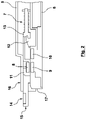
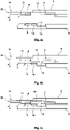
- the Figures 2 to 4c show a clutch 4, which is suitable for automated unlocking.
- the clutch 4 can, for example, according to a bag 1 of the arrangement 1 be arranged in the base area 3 and connect the two opposite side walls 2 of the pocket, which are aligned perpendicularly to the conveying direction x.
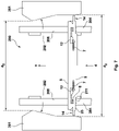
- An exemplary unloading station for the fully automatic unloading of the bag in the course of an automated actuation of the clutch 4 is in Figures 5 to 9 shown.
- the 2 shows an exemplary embodiment of a coupling 4 in the locking position of the actuating mechanism 7.
- the actuating mechanism has a magnetic slide 11 which is accommodated in one of the two coupling halves 5, 6 so as to be displaceable along the longitudinal direction thereof.
- the longitudinal direction of the coupling 4 or the coupling halves 5, 6 can extend in the width direction of the pocket, i.e. horizontally and perpendicularly to the conveying direction x (cf. 1 ).
- the magnetic slide 11 can be a mechanical preload in the 2 have shown locking position.
- a spiral spring is provided, which is accommodated in the coupling half 5 having the magnetic slide 11 and is supported inside the housing 16 of the coupling half 5 on a housing wall, through which the magnetic slide extends with a guide pin. in the in 2 locking position shown, the magnetic slide 11 protrudes with his Actuating end 14 out of the housing 16 of the first coupling half 5 by an adjustment path by which the actuating end can be adjusted between the locking position and the release position.
- the hook 12 In the locking position, the hook 12 extends into the undercut receptacle 13, with the undercut receptacle 13 reaching under the hook 12 with a projection, which forms the undercut behind which the hook 12 engages, and rests against the hook 12, so that the in 2 shown locking position of the actuating mechanism 7 is reproducibly defined.
- the coupling halves 5, 6 have magnetic elements 8, 9, 10. All magnetic elements 8, 9, 10 are preferably designed as permanent magnets. In particular, however, the magnetic element 9 can also be designed as a ferromagnetic element, for example having a ferrous metal.
- the magnetic elements 8 and 10 can each be designed as a permanent magnet and face each other with identical poles, so that the two coupling halves 5, 6 are repelled from each other.
- the two permanent magnets 8, 10 In the triggering position shown, not only are the two permanent magnets 8, 10 of the same polarity aligned opposite one another, but the hook 12 is also released from the undercut of the undercut receptacle 13, the two coupling halves 5, 6 can be detached from one another, which in Figure 3b is shown.
- the second coupling half 6 having the hook 12 can be detached from a positive-locking receptacle 17 of the first coupling half 5 . Since in the release position according to the Figures 3a and 3b the permanent magnets 8, 10 of the same polarity are in alignment, while the distance between the attracting, oppositely polarized magnetic elements 8, 9 is opposite the locking position (see 2 ) is increased, the repulsion between the permanent magnets 8, 10 outweighs a possibly also in the release position according to the Figures 3a and 3b still remaining, small force of attraction between the magnetic elements 8 and 9.
- the adjusting mechanism 7, in particular the magnetic slide 11, can return to the locking position take, where he automatically occupies this locking position due to its bias in the locking position due to, for example, the coil spring.
- the oppositely polarized magnetic elements 8 and 9 are brought back into alignment, whereby they themselves in the case of FIG Figure 4a partially spaced position shown, centering and further approaching each other due to the attraction force between the magnetic elements 8 and 9, as is shown in FIG Figure 4b is shown.
- the alignment of the coupling halves 5, 6 to each other, as shown in Figure 4a is shown, can be, for example, the initial state that the two coupling halves 5, 6 assume immediately after the unloading process, for example after leaving an unloading station 200, as shown in figure 5 is shown.
- the side walls 2 of the bag 1 can consist, for example, of a flexible textile material, so that the coupling halves 5, 6 bring the bag into a vertical position like a weight in the bottom area of the side walls 2, with the two side walls 2, for example, due to a likewise essentially vertical arrangement of an opening bracket at the upper end of the pocket 1 have already largely approached one another.
- a residual distance then remaining between the coupling halves 5, 6 as shown in Figure 4a is shown, can be bridged with the help of the magnetic attraction between the magnetic elements 8, 9, so that the two coupling halves 5, 6 in the Figures 4a to 4c Experience shown approach and locking.
- the magnetic slide 11 On the front side of the actuating end 14, with which the magnetic slide 11 protrudes from the housing 16 of the first coupling half 5, the magnetic slide 11 has a contact contour 15 with which it meets a pocket guide 201 of an unloading station 200 in the conveying direction x, which connects the magnetic slide 11 from the in 2 locking position shown in the in Figure 3a shown trigger position transferred.
- the unloading station 200 shown has a frame 209 which is designed as a pivoting frame and can be pivoted about a horizontal pivoting axis z directed perpendicularly to the conveying direction x.
- the pivot axis z can run horizontally, so that a vertical height, in particular of the pocket guide 201 of the unloading station 200, can be adjusted to a vertical height of the pocket by pivoting the pivot frame 209.
- the pockets are often of the same design in common overhead conveyors, it can happen that the pockets 1 vary in height due to the different filling of the pockets. For example, filling the pockets 1 with large or many items may cause the pocket to bulge, thereby losing vertical dimension.
- the unloading station 200 can have the pivoting frame 209 described above for shifting the bag guide 201 .
- the unloading station can be preceded by a sensor device in the conveying direction, which detects a dimension of the bags in the height direction and controls the swivel frame to carry out a suitable swiveling for receiving the bag measured in the height direction.
- the bags 1 are passed over the unloading station 200 so that the bag 1 comes into contact with the unloading station 200 essentially exclusively with its coupling 4 .
- Lateral guides 201 which are designed to taper conically, guide the pockets in the horizontal direction perpendicular to the conveying direction x.
- An additional guiding effect can be provided with the aid of the pocket driver 203 be, which is presently designed as a revolving toothed belt 205 with magnetic driver elements 204 arranged thereon, wherein the pocket driver 203 should not be limited to such an embodiment.
- the magnetic driver elements 204 have the particular advantage that they can be coupled to the magnetic elements 8, 9, 10, for example the clutch half 5 that has the magnetic slide 11, via the magnet 8 accommodated in the clutch half 5, so that a particularly process-reliable guidance of the clutch 4 through the tapered pocket guide 201 is possible.
- the clutches 4 can be fed to the pocket guide 201 via a ramp and a plateau following the ramp.
- the ramp can have the function of raising the clutch 4 and thus relieving it mechanically, for example with regard to a shearing force which acts on the clutch due to the objects kept in the pocket. This facilitates the actuation of the actuating mechanism and thus the release of the coupling halves 5, 6 from each other.
- the clutch 4 should be guided through the pocket guide 201 and in particular along the approach walls 202 of the pocket guide 201 in its raised and thus relieved state.
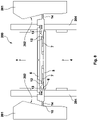
- FIG. 6 which, with regard to the supply and release of the clutch, are essentially components of the in figure 5 shown exemplary embodiment of the unloading station 200.
- the bag driver 203 already described can have a revolving belt.
- the figure 6 shows how the clutch 4 is fed to the pocket guide 201 by the pocket driver 203 and released at the pocket guide 201.
- the pocket driver 203 has driver elements 204 which are arranged on the outside on a revolving belt 205 .
- the belt 205 is designed as a toothed belt, which is guided around a plurality of deflection rollers.
- the belt 205 forms a ramp, so it is guided at an increasing acute angle to the horizontal.
- the two circulating belts 205 are at a distance from one another that is precisely dimensioned so that the pocket driver 203 on opposite longitudinal ends of the coupling 4 with its driver elements 204 can attack.
- the driver elements 204 have a magnet 211 which can be coupled to the magnetic element 8 of the clutch half 5 having the magnetic slide 11 .
- the pocket 1 fed to the pocket driver 203 in the horizontal conveying direction x will sooner or later come into the engagement area of a driver element 204, so that a magnetic coupling between the coupling 4 and the magnetic driver element 204 can take place.
- the revolving belts 205 of the pocket driver 203 are synchronized in relation to their respective driver elements 204 so that the driver elements 204 are aligned in pairs opposite one another and can thus be coupled to opposite ends of the clutch 4 .
- the clutch 4 thus experiences a defined advance in the conveying direction x or at an acute angle to the conveying direction x up the ramp of the belt 205 until the clutch 4 meets the pocket guide 201 .
- the coupling 4 has a coupling section which faces the side walls of the pocket (not shown) and which can be identified, for example, as the one in FIG figure 10 shown form-fitting section 19 can be formed.
- This form-fitting section 19 has a horizontal width perpendicular to the conveying direction x, which is greater than the clear width between the opposite pocket guides 201, so that the pocket is supported on the pocket guide 201.
- the clutch 4, via which the pocket 1 is supported on the pocket guide 201, is thereby mechanically relieved, which makes it easier to actuate the actuating mechanism 7 of the clutch 4.
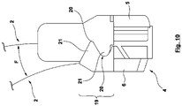
- the figure 10 shows a particularly advantageous embodiment of a coupling 4, in which the coupling halves 5, 6 are not coupled directly to the side walls 2 of the pocket 1, but via a form-fitting section 19, whereby the adjusting mechanism 7 in particular is protected from any force F acting on the side walls 2 acts and could lead to a canting of the two coupling halves 5, 6 in the locking position.
- the form-fitting section 19 can increase the carrying capacity of the pocket, within which process-reliable objects can be transported with the bag, in particular to the effect that accidental release of the clutch and thus falling out of the objects is prevented.
- the form-fitting section 19 can serve to prevent the hook from tilting in the form-fitting adapter, so that the process-reliable actuation of the adjusting mechanism 7 is ensured by shifting the magnetic slide 11 even with large and bulky objects which exert a considerable horizontal force on the side walls 2.
- the form-fitting section 19 has a groove 20 and a tongue 21 that engages in the groove 20, the groove being duplicated in that each of the two coupling halves 5, 6 also has a tongue 21 adjacent to its groove 20, each Coupling half 5, 6, the groove and tongue merge directly into one another.
Landscapes
- Engineering & Computer Science (AREA)
- Mechanical Engineering (AREA)
- Chain Conveyers (AREA)
Priority Applications (2)
| Application Number | Priority Date | Filing Date | Title |
|---|---|---|---|
| EP21168927.8A EP4074629B1 (fr) | 2021-04-16 | 2021-04-16 | Transporteur suspendu doté d'une station de déchargement |
| PCT/DE2022/100287 WO2022218477A1 (fr) | 2021-04-16 | 2022-04-14 | Convoyeur suspendu doté d'un poste de déchargement |
Applications Claiming Priority (1)
| Application Number | Priority Date | Filing Date | Title |
|---|---|---|---|
| EP21168927.8A EP4074629B1 (fr) | 2021-04-16 | 2021-04-16 | Transporteur suspendu doté d'une station de déchargement |
Publications (3)
| Publication Number | Publication Date |
|---|---|
| EP4074629A1 true EP4074629A1 (fr) | 2022-10-19 |
| EP4074629B1 EP4074629B1 (fr) | 2023-10-11 |
| EP4074629C0 EP4074629C0 (fr) | 2023-10-11 |
Family
ID=75581372
Family Applications (1)
| Application Number | Title | Priority Date | Filing Date |
|---|---|---|---|
| EP21168927.8A Active EP4074629B1 (fr) | 2021-04-16 | 2021-04-16 | Transporteur suspendu doté d'une station de déchargement |
Country Status (2)
| Country | Link |
|---|---|
| EP (1) | EP4074629B1 (fr) |
| WO (1) | WO2022218477A1 (fr) |
Families Citing this family (4)
| Publication number | Priority date | Publication date | Assignee | Title |
|---|---|---|---|---|
| DE102022211887A1 (de) * | 2022-11-10 | 2024-05-16 | Volkswagen Aktiengesellschaft | Logistikeinrichtung und Verfahren zum flexiblen Fördern und Speichern von Gütern und entsprechendes Fertigungssystem |
| WO2025077990A1 (fr) * | 2023-10-09 | 2025-04-17 | Psb Intralogistics Gmbh | Sac de transport |
| PL4585538T3 (pl) * | 2024-01-10 | 2026-02-23 | BEUMER Group GmbH & Co. KG | Worek dla sortownika worków, odpowiedni sortownik worków i sposób automatycznego rozładowywania worków |
| DE102024121396B3 (de) * | 2024-07-26 | 2025-05-22 | Ssi Schäfer Automation Gmbh (At) | Taschenöffnungsstation, Taschenschließstation, Hängeförderanlage und Verfahren zum Öffnen und Schließen einer Hängeförder-Transporttasche |
Citations (8)
| Publication number | Priority date | Publication date | Assignee | Title |
|---|---|---|---|---|
| EP2130968B1 (fr) | 2008-06-04 | 2010-09-15 | Dürkopp Fördertechnik GmbH | Sac de transport et installation de convoyage pour un sac de transport |
| EP2792620A1 (fr) * | 2013-03-22 | 2014-10-22 | Dürkopp Fördertechnik GmbH | Sac de transport pour le transport suspendu de marchandises ainsi que la station de chargement et le dispositif de transport pour ces sacs |
| EP2708478B1 (fr) | 2012-09-18 | 2014-11-19 | psb intralogistics GmbH | Sac de transport et dispositif de transport suspendu pour le transport suspendu d'objets, mécanisme de fermeture pour la fermeture d'un tel sac |
| WO2018078098A1 (fr) | 2016-10-27 | 2018-05-03 | Ferag Ag | Procédé et dispositif pour ouvrir un sac de transport |
| US10040641B2 (en) | 2015-01-26 | 2018-08-07 | Ferag Ag | Method for emptying the pockets of a transport device in the form of a suspension conveyor, and device for carrying out said method |
| US20200130952A1 (en) * | 2018-10-29 | 2020-04-30 | Intelligrated Headquarters, Llc | Pouch conveyor |
| EP3670393A1 (fr) | 2018-12-19 | 2020-06-24 | Stylogs GmbH | Agencement d'accouplement magnétique dans une installation de transport |
| WO2020150762A1 (fr) * | 2019-01-25 | 2020-07-30 | Tgw Mechanics Gmbh | Contenant pour produits à transporter pour un dispositif de transport suspendu et poste de déchargement servant à son déchargement |
-
2021
- 2021-04-16 EP EP21168927.8A patent/EP4074629B1/fr active Active
-
2022
- 2022-04-14 WO PCT/DE2022/100287 patent/WO2022218477A1/fr not_active Ceased
Patent Citations (9)
| Publication number | Priority date | Publication date | Assignee | Title |
|---|---|---|---|---|
| EP2130968B1 (fr) | 2008-06-04 | 2010-09-15 | Dürkopp Fördertechnik GmbH | Sac de transport et installation de convoyage pour un sac de transport |
| EP2708478B1 (fr) | 2012-09-18 | 2014-11-19 | psb intralogistics GmbH | Sac de transport et dispositif de transport suspendu pour le transport suspendu d'objets, mécanisme de fermeture pour la fermeture d'un tel sac |
| EP2792620A1 (fr) * | 2013-03-22 | 2014-10-22 | Dürkopp Fördertechnik GmbH | Sac de transport pour le transport suspendu de marchandises ainsi que la station de chargement et le dispositif de transport pour ces sacs |
| US10040641B2 (en) | 2015-01-26 | 2018-08-07 | Ferag Ag | Method for emptying the pockets of a transport device in the form of a suspension conveyor, and device for carrying out said method |
| WO2018078098A1 (fr) | 2016-10-27 | 2018-05-03 | Ferag Ag | Procédé et dispositif pour ouvrir un sac de transport |
| US20200130952A1 (en) * | 2018-10-29 | 2020-04-30 | Intelligrated Headquarters, Llc | Pouch conveyor |
| EP3670393A1 (fr) | 2018-12-19 | 2020-06-24 | Stylogs GmbH | Agencement d'accouplement magnétique dans une installation de transport |
| WO2020128941A1 (fr) | 2018-12-19 | 2020-06-25 | Stylogs Gmbh | Ensemble à entraînement magnétique dans une installation de transport |
| WO2020150762A1 (fr) * | 2019-01-25 | 2020-07-30 | Tgw Mechanics Gmbh | Contenant pour produits à transporter pour un dispositif de transport suspendu et poste de déchargement servant à son déchargement |
Also Published As
| Publication number | Publication date |
|---|---|
| WO2022218477A1 (fr) | 2022-10-20 |
| EP4074629B1 (fr) | 2023-10-11 |
| EP4074629C0 (fr) | 2023-10-11 |
Similar Documents
| Publication | Publication Date | Title |
|---|---|---|
| EP4074629B1 (fr) | Transporteur suspendu doté d'une station de déchargement | |
| DE3303184C2 (fr) | ||
| AT510754B1 (de) | Hängeförderer und antriebskette für den hängeförderer | |
| AT501826B1 (de) | Vorrichtung zum fördern und vereinzeln von ferromagnetischen teilen | |
| EP2881332B1 (fr) | Dispositif de transport de produits | |
| DE102010053590A1 (de) | Tragetasche für Fördergut und Förderanlage für eine Tragetasche | |
| DE3248882T1 (de) | Anordnung zum foerdern von werkstuecken | |
| DE10144518C1 (de) | Transporteinheit in einem Rücknahmesystem für Leergut | |
| DE4036214A1 (de) | Doppelspurfoerderanlage fuer bearbeitungs- und/oder montage-anlagen | |
| DE102008014831B4 (de) | Vorrichtung zum Puffern von Gegenständen | |
| EP3313624B1 (fr) | Système de chargement pour pièces | |
| EP2128051A1 (fr) | Installation de transport suspendue | |
| DE102011118303B4 (de) | Förderanlage mit einer Förderkette und Tragsegment für einen Förderträger einer Förderkette | |
| DE10133805B4 (de) | Einrichtung zum Zuführen von Bauteilen zu einer Montagestation | |
| EP4074628B1 (fr) | Sac pour un convoyeur aérien, ainsi que dispositif correspondant | |
| DE4342084C2 (de) | Vorrrichtung zum Ausrichten von Gegenständen | |
| EP1215142B1 (fr) | Dispositif de transport guidé sur rail et système de transport | |
| CH638730A5 (de) | Steuerbare verteilerfoerderanlage. | |
| EP3321217B1 (fr) | Système de transport destiné à transporter au moins une pièce à usiner | |
| EP2614018B1 (fr) | INSTALLATION DE CONVOYEUR SUSPENDU et ADAPTATEUR DE TRANSPORT ASSOCIÉ | |
| DE102012204824A1 (de) | Transport-Vorrichtung und Transport-Verfahren, welche mehrere transportierte Aufnahmevorrichtungen drehen | |
| DE3609751C2 (fr) | ||
| EP3050828B1 (fr) | Élement de transport pour des installations de transport de marchandises suspendues | |
| LU101646B1 (de) | Fördervorrichtung mit einem endlos umlaufenden Förderriemen zum Fördern einer Transporteinrichtung, mittels der ein Fördergut transportierbar ist | |
| DE102005047268B4 (de) | Vorrichtung zum Übergeben von Spritzen, Ampullen oder dergl. |
Legal Events
| Date | Code | Title | Description |
|---|---|---|---|
| PUAI | Public reference made under article 153(3) epc to a published international application that has entered the european phase |
Free format text: ORIGINAL CODE: 0009012 |
|
| STAA | Information on the status of an ep patent application or granted ep patent |
Free format text: STATUS: REQUEST FOR EXAMINATION WAS MADE |
|
| 17P | Request for examination filed |
Effective date: 20220303 |
|
| AK | Designated contracting states |
Kind code of ref document: A1 Designated state(s): AL AT BE BG CH CY CZ DE DK EE ES FI FR GB GR HR HU IE IS IT LI LT LU LV MC MK MT NL NO PL PT RO RS SE SI SK SM TR |
|
| P01 | Opt-out of the competence of the unified patent court (upc) registered |
Effective date: 20230411 |
|
| GRAP | Despatch of communication of intention to grant a patent |
Free format text: ORIGINAL CODE: EPIDOSNIGR1 |
|
| STAA | Information on the status of an ep patent application or granted ep patent |
Free format text: STATUS: GRANT OF PATENT IS INTENDED |
|
| RIC1 | Information provided on ipc code assigned before grant |
Ipc: B65G 1/137 20060101ALN20230525BHEP Ipc: B65G 47/61 20060101ALI20230525BHEP Ipc: B65G 17/20 20060101ALI20230525BHEP Ipc: B65G 9/00 20060101AFI20230525BHEP |
|
| INTG | Intention to grant announced |
Effective date: 20230622 |
|
| GRAS | Grant fee paid |
Free format text: ORIGINAL CODE: EPIDOSNIGR3 |
|
| GRAA | (expected) grant |
Free format text: ORIGINAL CODE: 0009210 |
|
| STAA | Information on the status of an ep patent application or granted ep patent |
Free format text: STATUS: THE PATENT HAS BEEN GRANTED |
|
| AK | Designated contracting states |
Kind code of ref document: B1 Designated state(s): AL AT BE BG CH CY CZ DE DK EE ES FI FR GB GR HR HU IE IS IT LI LT LU LV MC MK MT NL NO PL PT RO RS SE SI SK SM TR |
|
| REG | Reference to a national code |
Ref country code: GB Ref legal event code: FG4D Free format text: NOT ENGLISH |
|
| REG | Reference to a national code |
Ref country code: CH Ref legal event code: EP |
|
| REG | Reference to a national code |
Ref country code: DE Ref legal event code: R096 Ref document number: 502021001659 Country of ref document: DE |
|
| REG | Reference to a national code |
Ref country code: IE Ref legal event code: FG4D Free format text: LANGUAGE OF EP DOCUMENT: GERMAN |
|
| U01 | Request for unitary effect filed |
Effective date: 20231011 |
|
| P04 | Withdrawal of opt-out of the competence of the unified patent court (upc) registered |
Effective date: 20231031 |
|
| U07 | Unitary effect registered |
Designated state(s): AT BE BG DE DK EE FI FR IT LT LU LV MT NL PT SE SI Effective date: 20231106 |
|
| PG25 | Lapsed in a contracting state [announced via postgrant information from national office to epo] |
Ref country code: GR Free format text: LAPSE BECAUSE OF FAILURE TO SUBMIT A TRANSLATION OF THE DESCRIPTION OR TO PAY THE FEE WITHIN THE PRESCRIBED TIME-LIMIT Effective date: 20240112 |
|
| PG25 | Lapsed in a contracting state [announced via postgrant information from national office to epo] |
Ref country code: IS Free format text: LAPSE BECAUSE OF FAILURE TO SUBMIT A TRANSLATION OF THE DESCRIPTION OR TO PAY THE FEE WITHIN THE PRESCRIBED TIME-LIMIT Effective date: 20240211 |
|
| PG25 | Lapsed in a contracting state [announced via postgrant information from national office to epo] |
Ref country code: ES Free format text: LAPSE BECAUSE OF FAILURE TO SUBMIT A TRANSLATION OF THE DESCRIPTION OR TO PAY THE FEE WITHIN THE PRESCRIBED TIME-LIMIT Effective date: 20231011 |
|
| PG25 | Lapsed in a contracting state [announced via postgrant information from national office to epo] |
Ref country code: IS Free format text: LAPSE BECAUSE OF FAILURE TO SUBMIT A TRANSLATION OF THE DESCRIPTION OR TO PAY THE FEE WITHIN THE PRESCRIBED TIME-LIMIT Effective date: 20240211 Ref country code: GR Free format text: LAPSE BECAUSE OF FAILURE TO SUBMIT A TRANSLATION OF THE DESCRIPTION OR TO PAY THE FEE WITHIN THE PRESCRIBED TIME-LIMIT Effective date: 20240112 Ref country code: ES Free format text: LAPSE BECAUSE OF FAILURE TO SUBMIT A TRANSLATION OF THE DESCRIPTION OR TO PAY THE FEE WITHIN THE PRESCRIBED TIME-LIMIT Effective date: 20231011 |
|
| U20 | Renewal fee for the european patent with unitary effect paid |
Year of fee payment: 4 Effective date: 20240417 |
|
| PG25 | Lapsed in a contracting state [announced via postgrant information from national office to epo] |
Ref country code: RS Free format text: LAPSE BECAUSE OF FAILURE TO SUBMIT A TRANSLATION OF THE DESCRIPTION OR TO PAY THE FEE WITHIN THE PRESCRIBED TIME-LIMIT Effective date: 20231011 Ref country code: PL Free format text: LAPSE BECAUSE OF FAILURE TO SUBMIT A TRANSLATION OF THE DESCRIPTION OR TO PAY THE FEE WITHIN THE PRESCRIBED TIME-LIMIT Effective date: 20231011 Ref country code: NO Free format text: LAPSE BECAUSE OF FAILURE TO SUBMIT A TRANSLATION OF THE DESCRIPTION OR TO PAY THE FEE WITHIN THE PRESCRIBED TIME-LIMIT Effective date: 20240111 Ref country code: HR Free format text: LAPSE BECAUSE OF FAILURE TO SUBMIT A TRANSLATION OF THE DESCRIPTION OR TO PAY THE FEE WITHIN THE PRESCRIBED TIME-LIMIT Effective date: 20231011 |
|
| REG | Reference to a national code |
Ref country code: DE Ref legal event code: R097 Ref document number: 502021001659 Country of ref document: DE |
|
| PG25 | Lapsed in a contracting state [announced via postgrant information from national office to epo] |
Ref country code: CZ Free format text: LAPSE BECAUSE OF FAILURE TO SUBMIT A TRANSLATION OF THE DESCRIPTION OR TO PAY THE FEE WITHIN THE PRESCRIBED TIME-LIMIT Effective date: 20231011 |
|
| PG25 | Lapsed in a contracting state [announced via postgrant information from national office to epo] |
Ref country code: SK Free format text: LAPSE BECAUSE OF FAILURE TO SUBMIT A TRANSLATION OF THE DESCRIPTION OR TO PAY THE FEE WITHIN THE PRESCRIBED TIME-LIMIT Effective date: 20231011 |
|
| PG25 | Lapsed in a contracting state [announced via postgrant information from national office to epo] |
Ref country code: SM Free format text: LAPSE BECAUSE OF FAILURE TO SUBMIT A TRANSLATION OF THE DESCRIPTION OR TO PAY THE FEE WITHIN THE PRESCRIBED TIME-LIMIT Effective date: 20231011 Ref country code: SK Free format text: LAPSE BECAUSE OF FAILURE TO SUBMIT A TRANSLATION OF THE DESCRIPTION OR TO PAY THE FEE WITHIN THE PRESCRIBED TIME-LIMIT Effective date: 20231011 Ref country code: RO Free format text: LAPSE BECAUSE OF FAILURE TO SUBMIT A TRANSLATION OF THE DESCRIPTION OR TO PAY THE FEE WITHIN THE PRESCRIBED TIME-LIMIT Effective date: 20231011 Ref country code: CZ Free format text: LAPSE BECAUSE OF FAILURE TO SUBMIT A TRANSLATION OF THE DESCRIPTION OR TO PAY THE FEE WITHIN THE PRESCRIBED TIME-LIMIT Effective date: 20231011 |
|
| PLBE | No opposition filed within time limit |
Free format text: ORIGINAL CODE: 0009261 |
|
| STAA | Information on the status of an ep patent application or granted ep patent |
Free format text: STATUS: NO OPPOSITION FILED WITHIN TIME LIMIT |
|
| 26N | No opposition filed |
Effective date: 20240712 |
|
| PG25 | Lapsed in a contracting state [announced via postgrant information from national office to epo] |
Ref country code: MC Free format text: LAPSE BECAUSE OF FAILURE TO SUBMIT A TRANSLATION OF THE DESCRIPTION OR TO PAY THE FEE WITHIN THE PRESCRIBED TIME-LIMIT Effective date: 20231011 |
|
| PG25 | Lapsed in a contracting state [announced via postgrant information from national office to epo] |
Ref country code: MC Free format text: LAPSE BECAUSE OF FAILURE TO SUBMIT A TRANSLATION OF THE DESCRIPTION OR TO PAY THE FEE WITHIN THE PRESCRIBED TIME-LIMIT Effective date: 20231011 |
|
| REG | Reference to a national code |
Ref country code: CH Ref legal event code: PL |
|
| P05 | Withdrawal of opt-out of the competence of the unified patent court (upc) changed |
Free format text: CASE NUMBER: APP_584481/2023 Effective date: 20231106 |
|
| PG25 | Lapsed in a contracting state [announced via postgrant information from national office to epo] |
Ref country code: CH Free format text: LAPSE BECAUSE OF NON-PAYMENT OF DUE FEES Effective date: 20240430 |
|
| PG25 | Lapsed in a contracting state [announced via postgrant information from national office to epo] |
Ref country code: IE Free format text: LAPSE BECAUSE OF NON-PAYMENT OF DUE FEES Effective date: 20240416 |
|
| U20 | Renewal fee for the european patent with unitary effect paid |
Year of fee payment: 5 Effective date: 20250417 |
|
| PG25 | Lapsed in a contracting state [announced via postgrant information from national office to epo] |
Ref country code: CY Free format text: LAPSE BECAUSE OF FAILURE TO SUBMIT A TRANSLATION OF THE DESCRIPTION OR TO PAY THE FEE WITHIN THE PRESCRIBED TIME-LIMIT; INVALID AB INITIO Effective date: 20210416 |
|
| PG25 | Lapsed in a contracting state [announced via postgrant information from national office to epo] |
Ref country code: HU Free format text: LAPSE BECAUSE OF FAILURE TO SUBMIT A TRANSLATION OF THE DESCRIPTION OR TO PAY THE FEE WITHIN THE PRESCRIBED TIME-LIMIT; INVALID AB INITIO Effective date: 20210416 |
|
| GBPC | Gb: european patent ceased through non-payment of renewal fee |
Effective date: 20250416 |
|
| PG25 | Lapsed in a contracting state [announced via postgrant information from national office to epo] |
Ref country code: GB Free format text: LAPSE BECAUSE OF NON-PAYMENT OF DUE FEES Effective date: 20250416 |
|
| PG25 | Lapsed in a contracting state [announced via postgrant information from national office to epo] |
Ref country code: TR Free format text: LAPSE BECAUSE OF FAILURE TO SUBMIT A TRANSLATION OF THE DESCRIPTION OR TO PAY THE FEE WITHIN THE PRESCRIBED TIME-LIMIT Effective date: 20231011 |
|
| U20 | Renewal fee for the european patent with unitary effect paid |
Year of fee payment: 6 Effective date: 20260427 |