EP4074876B1 - Système de condensation pour lave-linge/sèche-linge combiné - Google Patents
Système de condensation pour lave-linge/sèche-linge combiné Download PDFInfo
- Publication number
- EP4074876B1 EP4074876B1 EP22166602.7A EP22166602A EP4074876B1 EP 4074876 B1 EP4074876 B1 EP 4074876B1 EP 22166602 A EP22166602 A EP 22166602A EP 4074876 B1 EP4074876 B1 EP 4074876B1
- Authority
- EP
- European Patent Office
- Prior art keywords
- condenser
- fluid
- tub
- appliance
- water
- Prior art date
- Legal status (The legal status is an assumption and is not a legal conclusion. Google has not performed a legal analysis and makes no representation as to the accuracy of the status listed.)
- Active
Links
Images

Classifications
-
- D—TEXTILES; PAPER
- D06—TREATMENT OF TEXTILES OR THE LIKE; LAUNDERING; FLEXIBLE MATERIALS NOT OTHERWISE PROVIDED FOR
- D06F—LAUNDERING, DRYING, IRONING, PRESSING OR FOLDING TEXTILE ARTICLES
- D06F58/00—Domestic laundry dryers
- D06F58/20—General details of domestic laundry dryers
- D06F58/24—Condensing arrangements
-
- D—TEXTILES; PAPER
- D06—TREATMENT OF TEXTILES OR THE LIKE; LAUNDERING; FLEXIBLE MATERIALS NOT OTHERWISE PROVIDED FOR
- D06F—LAUNDERING, DRYING, IRONING, PRESSING OR FOLDING TEXTILE ARTICLES
- D06F25/00—Washing machines with receptacles, e.g. perforated, having a rotary movement, e.g. oscillatory movement, the receptacle serving both for washing and for centrifugally separating water from the laundry and having further drying means, e.g. using hot air
-
- D—TEXTILES; PAPER
- D06—TREATMENT OF TEXTILES OR THE LIKE; LAUNDERING; FLEXIBLE MATERIALS NOT OTHERWISE PROVIDED FOR
- D06F—LAUNDERING, DRYING, IRONING, PRESSING OR FOLDING TEXTILE ARTICLES
- D06F34/00—Details of control systems for washing machines, washer-dryers or laundry dryers
- D06F34/14—Arrangements for detecting or measuring specific parameters
- D06F34/26—Condition of the drying air, e.g. air humidity or temperature
-
- D—TEXTILES; PAPER
- D06—TREATMENT OF TEXTILES OR THE LIKE; LAUNDERING; FLEXIBLE MATERIALS NOT OTHERWISE PROVIDED FOR
- D06F—LAUNDERING, DRYING, IRONING, PRESSING OR FOLDING TEXTILE ARTICLES
- D06F39/00—Details of washing machines not specific to a single type of machines covered by groups D06F9/00 - D06F27/00
- D06F39/04—Heating arrangements
-
- D—TEXTILES; PAPER
- D06—TREATMENT OF TEXTILES OR THE LIKE; LAUNDERING; FLEXIBLE MATERIALS NOT OTHERWISE PROVIDED FOR
- D06F—LAUNDERING, DRYING, IRONING, PRESSING OR FOLDING TEXTILE ARTICLES
- D06F39/00—Details of washing machines not specific to a single type of machines covered by groups D06F9/00 - D06F27/00
- D06F39/08—Liquid supply or discharge arrangements
- D06F39/083—Liquid discharge or recirculation arrangements
-
- D—TEXTILES; PAPER
- D06—TREATMENT OF TEXTILES OR THE LIKE; LAUNDERING; FLEXIBLE MATERIALS NOT OTHERWISE PROVIDED FOR
- D06F—LAUNDERING, DRYING, IRONING, PRESSING OR FOLDING TEXTILE ARTICLES
- D06F39/00—Details of washing machines not specific to a single type of machines covered by groups D06F9/00 - D06F27/00
- D06F39/08—Liquid supply or discharge arrangements
- D06F39/083—Liquid discharge or recirculation arrangements
- D06F39/085—Arrangements or adaptations of pumps
-
- D—TEXTILES; PAPER
- D06—TREATMENT OF TEXTILES OR THE LIKE; LAUNDERING; FLEXIBLE MATERIALS NOT OTHERWISE PROVIDED FOR
- D06F—LAUNDERING, DRYING, IRONING, PRESSING OR FOLDING TEXTILE ARTICLES
- D06F39/00—Details of washing machines not specific to a single type of machines covered by groups D06F9/00 - D06F27/00
- D06F39/08—Liquid supply or discharge arrangements
- D06F39/088—Liquid supply arrangements
Definitions
- the present invention relates to laundry appliances such as combination washer/dryer appliances and, more particularly, to a condensing system for combination washer/dryer appliances that reclaims and recirculates water condensate.
- Laundry appliances / laundry machines are prolific in both residential and commercial settings. Traditionally, separate washer and dryer machines have been used in tandem to clean and dry laundry. However, there is a growing market for combination washer/dryer appliances where a single machine performs both the washing and drying functions, thereby eliminating the need for two separate machines. There are a number of different names used to describe combination washer/dryer appliances, including without limitation, "washer/dryer combos" and "all-in-one washer/dryers.” While these units save space compared to separate washer and dryer machines, combining the washing and drying functions into a single appliance presents a number of engineering challenges.
- condenser solutions exist to overcome the drying time issue.
- One such solution is using the main wash cold water valve to spray pulses of cold water for less than one second every 20 seconds across the front of the drum. This solution produces minimal condensing and also lowers the temperature of the tub, which reduces drying performance.
- Another condenser solution uses the main wash cold water valve to spray pulses of water for approximately 10 seconds every minute or 20 seconds every two minutes, for example, through a distribution nozzle at the top of a condenser. This sprays water down the length of the condenser and tub and into a drain.
- These designs utilize fluid-to-fluid heat transfer between cold water and the drying air stream, but residence time is low, which results in poor condensation.
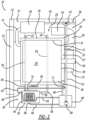
- a condensing system for a laundry appliance includes an exhaust air recirculation loop, a condenser, and a condenser coil recirculation loop.
- the exhaust air recirculation loop includes an air inlet conduit and an air outlet conduit.
- the air inlet conduit extends between an exhaust air inlet port and a condenser inlet port.
- the air outlet conduit extends between a condenser outlet port and a drying air return port.
- the condenser is connected to and is arranged in fluid communication with the condenser inlet port of the air inlet conduit and the condenser outlet port of the air outlet conduit.
- the condenser further includes a water condensate outlet and a condenser drain line that is connected to the water condensate outlet.
- the water condensate outlet is positioned to drain water condensate collecting in the condenser.
- a condenser coil is positioned within the condenser.
- the condenser coil includes a fluid inlet and a fluid outlet and the condenser coil recirculation loop includes a fluid supply line that is connected to the fluid inlet of the condenser coil and a fluid return line that is connected to the fluid outlet of the condenser coil.
- a common sump is arranged in fluid communication with both the fluid return line of the condenser coil recirculation loop and the condenser drain line such that the common sump is configured to collect fluid exiting the condenser coil and the water condensate draining from the condenser.
- the common sump is also arranged in fluid communication with both the fluid supply line of the condenser coil recirculation loop and a fresh water inlet of the laundry appliance such that the common sump is configured to supply the fluid and water condensate returning to the common sump to both the condenser coil for cooling enhanced condensation and the fresh water inlet for use in a washing cycle of the laundry appliance.
- the fluid and water condensate returning to the common sump is supplied to the fresh water inlet where it combines with fresh water before being used in the washing cycle of the laundry appliance.
- the fresh water inlet includes at least one valve that is arranged to permit fluid flow out of the fluid transfer conduit in a first position and permit the flow of fresh water into the fluid transfer conduit in a second position.
- a controller is arranged in electronic communication with the pump and/or the valve of the fresh water inlet. The controller is programmed to control the pump and/or the valve of the fresh water inlet to supply the fluid to the condenser coil in pulses to maintain the condenser coil at a cold temperature as water vapor in hot exhaust air from the air inlet conduit condenses on the condenser coil.
- the combination washer/dryer appliance further includes a common sump that is arranged in fluid communication with both the fluid return line of the condenser coil recirculation loop and the condenser drain line such that the common sump is configured to collect fluid exiting the condenser coil and the water condensate draining from the condenser.
- the common sump is also arranged in fluid communication with both the fluid supply line of the condenser coil recirculation loop and the fresh water inlet such that the common sump is configured to supply the fluid and water condensate returning to the common sump to both the condenser coil for cooling enhanced condensation and the fresh water inlet for use in a washing cycle of the combination washer/dryer appliance.
- the fluid, water condensate, and wash water returning to the common sump is supplied to the wash water dispensing system for use during the washing cycle of the combination washer/dryer appliance.
- a pump is located in fluid communication with the sump and the fluid transfer conduit. The pump is configured to pump the fluid, water condensate, and wash water out of the common sump and into the fluid transfer conduit.
- the fluid supply line of the condenser coil recirculation loop is arranged in fluid communication with the fluid transfer conduit.
- the combination washer/dryer appliance further includes a Peltier cell attached to the condenser.
- the Peltier cell includes a cold side that is arranged to promote the condensation of water vapor within the condenser and a hot side that is arranged to reheat the drying air exiting the condenser through the condenser outlet port.
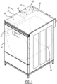
- a combination washer/dryer appliance generally includes an appliance housing, an appliance door that is pivotally mounted to the appliance housing, and a drum and tub assembly positioned inside the appliance housing.
- the drum and tub assembly includes a tub and a drum that is rotatably supported within the tub.
- a wash water dispensing system is arranged inside the appliance housing to dispense wash water into the tub.
- the combination washer/dryer appliance further includes a fluid transfer conduit that is connected in fluid communication with the common sump and both the fluid supply line of the condenser coil and the wash water dispensing system such that the fluid and water condensate returning to the common sump is recirculated to both the condenser coil and the wash water dispensing system for use in a washing cycle of the combination washer/dryer appliance.
- the present disclosure provides a condensation system that reduces the drying time of a combination washer/dryer appliance and has the added benefit of returning recycled and reclaimed water to the common sump to be reused in the condenser coil recirculation loop and/or the wash cycle of the combination washer/dryer appliance.
- this reduces the water usage of the combination washer/dryer appliance.
- the present disclosure provides faster cycle times and reduced load temperature to improve care of the garments and reduce shrinkage and lint generation.
- the combination washer/dryer appliance 10 includes a wash water dispensing system 37 that is connected to a fresh water inlet 39 located at the rear of the appliance housing 12.
- the wash water dispensing system 37 is arranged inside the appliance housing 12 and is configured to received fresh water from the fresh water inlet 39 and dispense wash water into the tub 20 during a wash cycle.
- the wash water dispensing system 37 may include one or more water inlet valves 41, connected to the fresh water inlet 39, and one or more hot and cold water inlet lines 43 that extend from the water inlet valves 41 to a dispenser box 45.
- the dispenser box 45 may include a dosing drawer for receiving doses of detergent, bleach, fabric softener, and the like.
Landscapes
- Engineering & Computer Science (AREA)
- Textile Engineering (AREA)
- Detail Structures Of Washing Machines And Dryers (AREA)
Claims (12)
- Machine lavante/séchante combinée (10), comprenant :un logement d'appareil (12) ;une porte d'appareil (14) montée pivotante au logement d'appareil (12) ;un ensemble tambour et cuve (16) positionné à l'intérieur du logement d'appareil (12), l'ensemble tambour et cuve (16) incluant une cuve (20) et un tambour (18) qui est supporté de manière rotative à l'intérieur de la cuve (20) ;un orifice d'entrée d'eau douce (39) disposé à l'intérieur du logement d'appareil (12) et configuré pour être raccordé à une source d'eau douce ;une boucle de recirculation d'air d'échappement (59) incluant un conduit d'entrée d'air (61) et un conduit de sortie d'air (63), le conduit d'entrée d'air (61) s'étendant entre un orifice d'entrée d'air d'échappement (22) et un orifice d'entrée de condenseur (34), le conduit de sortie d'air (63) s'étendant entre un orifice de sortie de condenseur (36) et un orifice de retour d'air séchant (24) ;un condenseur (32) raccordé et agencé en communication fluidique avec l'orifice d'entrée de condenseur (34) du conduit d'entrée d'air (61) et l'orifice de sortie de condenseur (36) du conduit de sortie d'air (63), le condenseur (32) incluant un orifice de sortie de condensat d'eau (38) positionné pour vidanger le condensat d'eau se rassemblant dans le condenseur (32) ;une bobine de condenseur (40) positionnée à l'intérieur du condenseur (32), la bobine de condenseur (40) incluant un orifice d'entrée de fluide et un orifice de sortie de fluide ;une boucle de recirculation de bobine de condenseur (65) incluant une conduite d'alimentation de fluide (42) raccordée à l'orifice d'entrée de fluide de la bobine de condenseur (40) et une conduite de retour de fluide (44) raccordée à l'orifice de sortie de fluide de la bobine de condenseur (40) ;une conduite de vidange de condenseur (46) raccordée à l'orifice de sortie de condensat d'eau (38) ; etun puisard commun (48) agencé en communication fluidique avec à la fois la conduite de retour de fluide (44) et la conduite de vidange de condenseur (46) de sorte que le puisard commun (48) est configuré pour collecter le fluide sortant de la bobine de condenseur (40) et le condensat d'eau s'écoulant du condenseur (32) ;un conduit de transfert de fluide (67) raccordé au, et s'étendant entre le, puisard commun (48) et l'orifice d'entrée d'eau douce (39) ;une pompe (69) localisée en communication fluidique avec le puisard commun (48) et le conduit de transfert de fluide (67),caractérisée en ce que la pompe (69) est configurée pour pomper le fluide et le condensat d'eau hors du puisard commun (48) et dans le conduit de transfert de fluide (67),dans laquelle le puisard commun (48) est agencé en communication fluidique avec à la fois la conduite d'alimentation de fluide (42) de la boucle de recirculation de bobine de condenseur (65) et l'orifice d'entrée d'eau douce (39) de sorte que le puisard commun (48) est configuré pour alimenter le fluide et le condensat d'eau revenant au puisard commun (48) vers à la fois la bobine de condenseur (40) et l'orifice d'entrée d'eau douce (39) pour l'utilisation dans un cycle de lavage de la machine lavante/séchante combinée (10).
- Machine lavante/séchante combinée (10) selon la revendication 1, dans laquelle le fluide et le condensat d'eau revenant au puisard commun (48) sont alimenté à l'orifice d'entrée d'eau douce (39) où ils se combinent à l'eau douce avant d'être utilisés dans le cycle de lavage de l'appareil de blanchisserie.
- Machine lavante/séchante combinée (10) selon la revendication 1 ou 2, dans laquelle l'orifice d'entrée d'eau douce (39) inclut au moins une valve (41) qui est agencée pour permettre au fluide de s'écouler hors du conduit de transfert de fluide (67) dans une première position et pour permettre l'écoulement d'eau douce dans le conduit de transfert de fluide (67) dans une seconde position.
- Machine lavante/séchante combinée (10) selon la revendication 3, comprenant en outre :
un dispositif de commande qui est agencé en communication électronique avec au moins l'une de la pompe (69) et de la valve (41) de l'orifice d'entrée d'eau douce (39), le dispositif de commande étant programmé pour commander au moins l'une de la pompe (69) et de la valve (41) de l'orifice d'entrée d'eau douce (39) pour alimenter le fluide à la bobine de condenseur (40) en impulsions pour maintenir la bobine de condenseur (40) à une température froide lorsque la vapeur d'eau dans l'air d'échappement chaud provenant du conduit d'entrée d'air (61) se condense sur la bobine de condenseur (40). - Machine lavante/séchante combinée (10) selon l'une des revendications 1 à 4, dans laquelle la conduite d'alimentation de fluide (42) de la boucle de recirculation de bobine de condenseur (65) est agencée en communication fluidique avec le conduit de transfert de fluide (67).
- Machine lavante/séchante combinée (10) selon la revendication 1 ou 2, comprenant en outre :
une conduite de vidange de cuve de lavage (49) raccordée en communication fluidique avec, et s'étendant entre, la cuve (20) et le puisard commun (48), la conduite de vidange de cuve de lavage (49) configurée pour recevoir l'eau de lavage s'écoulant de la cuve (20) et pour transporter l'eau de lavage vers le puisard commun (48). - Machine lavante/séchante combinée (10) selon la revendication 6, comprenant en outre :un système de distribution d'eau de lavage (37) raccordé à l'orifice d'entrée d'eau douce (39), le système de distribution d'eau de lavage (37) est agencé à l'intérieur du logement d'appareil (12) et est configuré pour recevoir l'eau douce de l'orifice d'entrée d'eau douce (39) et distribuer l'eau de lavage dans la cuve (20) ; et dans laquellele conduit de transfert de fluide (67) est raccordé en communication fluidique avec le système de distribution d'eau de lavage (37), dans laquelle le fluide, le condensat d'eau, et l'eau de lavage revenant au puisard commun (48) sont alimentés au système de distribution d'eau de lavage (37) pour l'utilisation durant le cycle de lavage de la machine lavante/séchante combinée (10).
- Machine lavante/séchante combinée (10) selon la revendication 6 ou 7, dans laquelle la conduite d'alimentation de fluide (42) de la boucle de recirculation de bobine de condenseur (65) est agencée en communication fluidique avec le conduit de transfert de fluide (67).
- Machine lavante/séchante combinée (10) selon la revendication 1, comprenant en outre :une unité de chauffage (51) disposée à l'intérieur du logement d'appareil (12), l'unité de chauffage (51) incluant un dispositif de chauffage (53) et une canalisation de chauffage (55) s'étendant depuis le dispositif de chauffage (53) vers une paroi arrière (29) du tambour (18), la canalisation de chauffage (55) étant configurée pour souffler de l'air séchant chaud à travers des perforations dans la paroi arrière (29) du tambour (18),dans laquelle le conduit d'entrée d'air (61) et l'orifice d'entrée d'air d'échappement (22) sont agencés le long d'une paroi latérale (25) de la cuve (20) et sont configurés pour recevoir l'air d'échappement chaud sortant du tambour (18),dans laquelle le conduit de sortie d'air (63) et l'orifice de retour d'air séchant (24) sont agencés le long de la paroi latérale (25) de la cuve (20) entre le conduit d'entrée d'air (61) et une paroi arrière (23) de la cuve (20) et sont configurés pour alimenter l'air séchant sortant du condenseur (32) au tambour (18).
- Machine lavante/séchante combinée (10) selon la revendication 1 ou 9, comprenant en outre :
un capteur de température (60) positionné dans le conduit d'entrée d'air (61) pour prendre des mesures de température de l'air d'échappement chaud s'écoulant à travers le conduit d'entrée d'air (61). - Machine lavante/séchante combinée (10) selon la revendication 1, 9 ou 10, comprenant en outre :
une cellule de Peltier (70) fixée au condenseur (32), la cellule de Peltier (70) incluant un côté froid (72) agencé pour favoriser la condensation de vapeur d'eau à l'intérieur du condenseur (32) et un côté chaud (74) agencé pour chauffer à nouveau l'air séchant sortant du condenseur (32) à travers l'orifice de sortie de condenseur (36). - Machine lavante/séchante combinée (10) selon la revendication 1, 9, 10 ou 11, comprenant en outre :
un ventilateur (50) monté sur la cuve (20) et positionné pour diriger le flux d'air refroidissant sur le condenseur (32) pour refroidir de manière supplémentaire le condenseur (32) et favoriser la condensation de vapeur d'eau à l'intérieur du condenseur (32).
Applications Claiming Priority (2)
| Application Number | Priority Date | Filing Date | Title |
|---|---|---|---|
| US202163175813P | 2021-04-16 | 2021-04-16 | |
| US17/691,357 US11802364B2 (en) | 2021-04-16 | 2022-03-10 | Condensing system for combination washer/dryer appliance |
Publications (2)
| Publication Number | Publication Date |
|---|---|
| EP4074876A1 EP4074876A1 (fr) | 2022-10-19 |
| EP4074876B1 true EP4074876B1 (fr) | 2024-11-27 |
Family
ID=81325515
Family Applications (1)
| Application Number | Title | Priority Date | Filing Date |
|---|---|---|---|
| EP22166602.7A Active EP4074876B1 (fr) | 2021-04-16 | 2022-04-04 | Système de condensation pour lave-linge/sèche-linge combiné |
Country Status (3)
| Country | Link |
|---|---|
| US (1) | US11802364B2 (fr) |
| EP (1) | EP4074876B1 (fr) |
| CN (1) | CN115216949A (fr) |
Families Citing this family (2)
| Publication number | Priority date | Publication date | Assignee | Title |
|---|---|---|---|---|
| US12467179B2 (en) * | 2022-08-23 | 2025-11-11 | Whirlpool Corporation | Apparatus for heating inlet air in a combination washer/dryer |
| CN117137356A (zh) * | 2023-09-18 | 2023-12-01 | 箭牌家居集团股份有限公司 | 毛巾架 |
Family Cites Families (20)
| Publication number | Priority date | Publication date | Assignee | Title |
|---|---|---|---|---|
| NL7312134A (nl) | 1973-09-03 | 1975-03-05 | Schuurink Fredrik Adolf | Droger, in het bijzonder voor wasgoed, met recirculatie van de lucht en condensatie. |
| IT1007554B (it) | 1973-10-26 | 1976-10-30 | Ire Ind Riunite Eurodomesti Ci | Apparecchio asciugature domestico a tamburo rotante |
| DE2451339C2 (de) | 1974-10-25 | 1982-02-18 | Bosch-Siemens Hausgeräte GmbH, 7000 Stuttgart | Kombination eines Waschvollautomaten mit einem Kondensationstrockner |
| DE3618920A1 (de) | 1986-06-05 | 1987-12-10 | Bosch Siemens Hausgeraete | Waeschetrockner |
| KR20050097277A (ko) * | 2004-04-01 | 2005-10-07 | 주식회사 대우일렉트로닉스 | 드럼세탁기용 응축기 |
| KR100697021B1 (ko) | 2005-04-06 | 2007-03-20 | 엘지전자 주식회사 | 건조 겸용 세탁기 |
| JP2007135728A (ja) * | 2005-11-16 | 2007-06-07 | Hitachi Appliances Inc | 洗濯乾燥機 |
| DE102005056942A1 (de) | 2005-11-29 | 2007-05-31 | BSH Bosch und Siemens Hausgeräte GmbH | Wärmetrockner mit Peltier-Wärmepumpe |
| DE602007009374D1 (de) * | 2007-07-26 | 2010-11-04 | Candy Spa | Wäschetrockner |
| DE102007061519A1 (de) | 2007-12-20 | 2009-06-25 | BSH Bosch und Siemens Hausgeräte GmbH | Wäschetrocknungsgerät mit einer Feuchtigkeitsbestimmungseinrichtung und Ver-fahren zum Betreiben eines Wäschetrocknungsgeräts |
| KR101128810B1 (ko) | 2009-01-09 | 2012-03-23 | 엘지전자 주식회사 | 세탁장치 |
| EP2372012B1 (fr) | 2010-03-30 | 2016-08-31 | DBK David + Baader GmbH | Unité de condensateur, appareil domestique, et procédé de contrôle de cet appareil domestique |
| SI23343A (sl) | 2010-04-15 | 2011-10-28 | Gorenje Gospodinjski Aparati, D.D. | Kondenzacijski sušilnik perila |
| EP2796613B1 (fr) | 2013-04-23 | 2020-11-11 | Whirlpool Corporation | Sèche-linge ou lave-linge sèche-linge et procédé pour son fonctionnement |
| EP3192912A1 (fr) | 2016-01-14 | 2017-07-19 | BSH Hausgeräte GmbH | Sèche-linge avec un circuit d'eau de refroidissement |
| KR102532471B1 (ko) * | 2016-02-17 | 2023-05-12 | 엘지전자 주식회사 | 세탁물 처리장치 및 그 운전방법 |
| CN107815812B (zh) * | 2016-09-13 | 2020-06-09 | 青岛海尔滚筒洗衣机有限公司 | 一种高效冷凝器和具有该冷凝器的洗衣机 |
| CN107287815B (zh) | 2017-07-11 | 2021-12-17 | 青岛海尔滚筒洗衣机有限公司 | 一种衣物洗护一体机 |
| CN110735306B (zh) | 2018-07-18 | 2023-03-10 | 青岛胶南海尔洗衣机有限公司 | 一种冷凝水循环利用系统及干衣机 |
| CN111021009A (zh) | 2019-11-22 | 2020-04-17 | 珠海格力电器股份有限公司 | 烘干组件、烘干器和洗干一体机 |
-
2022
- 2022-03-10 US US17/691,357 patent/US11802364B2/en active Active
- 2022-04-04 EP EP22166602.7A patent/EP4074876B1/fr active Active
- 2022-04-15 CN CN202210395989.5A patent/CN115216949A/zh active Pending
Also Published As
| Publication number | Publication date |
|---|---|
| US20220333291A1 (en) | 2022-10-20 |
| US11802364B2 (en) | 2023-10-31 |
| CN115216949A (zh) | 2022-10-21 |
| EP4074876A1 (fr) | 2022-10-19 |
Similar Documents
| Publication | Publication Date | Title |
|---|---|---|
| US6966124B2 (en) | Drum washing machine | |
| US9194076B2 (en) | Method for controlling laundry machine | |
| KR102150442B1 (ko) | 의류 처리장치 | |
| EP1917392B1 (fr) | Procédé de fonctionnement pour une machine à laver | |
| US7814770B2 (en) | Multi-functional laundry device and controlling method for the same | |
| KR101265616B1 (ko) | 건조기 및 그 제어방법 | |
| EP2565320B1 (fr) | Appareil de traitement de linge | |
| KR100879572B1 (ko) | 의류처리 시스템 및 이의 급수 제어방법 | |
| US12000073B2 (en) | Adjusted operation of a combination washer/dryer appliance | |
| US20110005279A1 (en) | Laundry treating machine and control method of the same | |
| EP4074876B1 (fr) | Système de condensation pour lave-linge/sèche-linge combiné | |
| US20240229337A1 (en) | Laundry appliance filter and frame | |
| EP1852534A1 (fr) | Machine à laver et à sécher avec circuit de condensation additionnel | |
| US12522970B2 (en) | Door assembly for a combination laundry appliance | |
| US20250027262A1 (en) | Process air vent for laundry appliance | |
| US12398501B2 (en) | Laundry appliance drainage | |
| CN103237936B (zh) | 用于清洁洗涤干燥机中的空气通道的方法以及适用所述方法的洗涤干燥机 | |
| US20240229345A1 (en) | Laundry appliance filter with biasing elements | |
| EP0704569A1 (fr) | Machines à laver et à sécher le linge | |
| KR100662567B1 (ko) | 세탁기 | |
| JP2021177865A (ja) | 洗濯乾燥機 | |
| JP7798840B2 (ja) | 洗濯乾燥機 | |
| KR101513046B1 (ko) | 세탁기 제어방법 | |
| JP7757144B2 (ja) | 洗濯乾燥機 | |
| US12460343B2 (en) | Laundry appliance filter assembly retention latch |
Legal Events
| Date | Code | Title | Description |
|---|---|---|---|
| PUAI | Public reference made under article 153(3) epc to a published international application that has entered the european phase |
Free format text: ORIGINAL CODE: 0009012 |
|
| STAA | Information on the status of an ep patent application or granted ep patent |
Free format text: STATUS: THE APPLICATION HAS BEEN PUBLISHED |
|
| AK | Designated contracting states |
Kind code of ref document: A1 Designated state(s): AL AT BE BG CH CY CZ DE DK EE ES FI FR GB GR HR HU IE IS IT LI LT LU LV MC MK MT NL NO PL PT RO RS SE SI SK SM TR |
|
| RAP3 | Party data changed (applicant data changed or rights of an application transferred) |
Owner name: WHIRLPOOL CORPORATION |
|
| STAA | Information on the status of an ep patent application or granted ep patent |
Free format text: STATUS: REQUEST FOR EXAMINATION WAS MADE |
|
| 17P | Request for examination filed |
Effective date: 20230417 |
|
| RBV | Designated contracting states (corrected) |
Designated state(s): AL AT BE BG CH CY CZ DE DK EE ES FI FR GB GR HR HU IE IS IT LI LT LU LV MC MK MT NL NO PL PT RO RS SE SI SK SM TR |
|
| RIC1 | Information provided on ipc code assigned before grant |
Ipc: D06F 58/24 20060101ALN20240206BHEP Ipc: D06F 39/08 20060101ALN20240206BHEP Ipc: D06F 25/00 20060101AFI20240206BHEP |
|
| GRAP | Despatch of communication of intention to grant a patent |
Free format text: ORIGINAL CODE: EPIDOSNIGR1 |
|
| STAA | Information on the status of an ep patent application or granted ep patent |
Free format text: STATUS: GRANT OF PATENT IS INTENDED |
|
| RIC1 | Information provided on ipc code assigned before grant |
Ipc: D06F 58/24 20060101ALN20240222BHEP Ipc: D06F 39/08 20060101ALN20240222BHEP Ipc: D06F 25/00 20060101AFI20240222BHEP |
|
| INTG | Intention to grant announced |
Effective date: 20240318 |
|
| GRAJ | Information related to disapproval of communication of intention to grant by the applicant or resumption of examination proceedings by the epo deleted |
Free format text: ORIGINAL CODE: EPIDOSDIGR1 |
|
| STAA | Information on the status of an ep patent application or granted ep patent |
Free format text: STATUS: REQUEST FOR EXAMINATION WAS MADE |
|
| P01 | Opt-out of the competence of the unified patent court (upc) registered |
Effective date: 20240520 |
|
| INTC | Intention to grant announced (deleted) | ||
| GRAP | Despatch of communication of intention to grant a patent |
Free format text: ORIGINAL CODE: EPIDOSNIGR1 |
|
| STAA | Information on the status of an ep patent application or granted ep patent |
Free format text: STATUS: GRANT OF PATENT IS INTENDED |
|
| RIC1 | Information provided on ipc code assigned before grant |
Ipc: D06F 58/24 20060101ALN20240611BHEP Ipc: D06F 39/08 20060101ALN20240611BHEP Ipc: D06F 25/00 20060101AFI20240611BHEP |
|
| RIC1 | Information provided on ipc code assigned before grant |
Ipc: D06F 58/24 20060101ALN20240625BHEP Ipc: D06F 39/08 20060101ALN20240625BHEP Ipc: D06F 25/00 20060101AFI20240625BHEP |
|
| INTG | Intention to grant announced |
Effective date: 20240715 |
|
| GRAS | Grant fee paid |
Free format text: ORIGINAL CODE: EPIDOSNIGR3 |
|
| GRAA | (expected) grant |
Free format text: ORIGINAL CODE: 0009210 |
|
| STAA | Information on the status of an ep patent application or granted ep patent |
Free format text: STATUS: THE PATENT HAS BEEN GRANTED |
|
| AK | Designated contracting states |
Kind code of ref document: B1 Designated state(s): AL AT BE BG CH CY CZ DE DK EE ES FI FR GB GR HR HU IE IS IT LI LT LU LV MC MK MT NL NO PL PT RO RS SE SI SK SM TR |
|
| REG | Reference to a national code |
Ref country code: GB Ref legal event code: FG4D |
|
| REG | Reference to a national code |
Ref country code: CH Ref legal event code: EP |
|
| REG | Reference to a national code |
Ref country code: DE Ref legal event code: R096 Ref document number: 602022008062 Country of ref document: DE |
|
| REG | Reference to a national code |
Ref country code: IE Ref legal event code: FG4D |
|
| REG | Reference to a national code |
Ref country code: LT Ref legal event code: MG9D |
|
| REG | Reference to a national code |
Ref country code: NL Ref legal event code: MP Effective date: 20241127 |
|
| PG25 | Lapsed in a contracting state [announced via postgrant information from national office to epo] |
Ref country code: IS Free format text: LAPSE BECAUSE OF FAILURE TO SUBMIT A TRANSLATION OF THE DESCRIPTION OR TO PAY THE FEE WITHIN THE PRESCRIBED TIME-LIMIT Effective date: 20250327 Ref country code: HR Free format text: LAPSE BECAUSE OF FAILURE TO SUBMIT A TRANSLATION OF THE DESCRIPTION OR TO PAY THE FEE WITHIN THE PRESCRIBED TIME-LIMIT Effective date: 20241127 Ref country code: PT Free format text: LAPSE BECAUSE OF FAILURE TO SUBMIT A TRANSLATION OF THE DESCRIPTION OR TO PAY THE FEE WITHIN THE PRESCRIBED TIME-LIMIT Effective date: 20250327 |
|
| PG25 | Lapsed in a contracting state [announced via postgrant information from national office to epo] |
Ref country code: NL Free format text: LAPSE BECAUSE OF FAILURE TO SUBMIT A TRANSLATION OF THE DESCRIPTION OR TO PAY THE FEE WITHIN THE PRESCRIBED TIME-LIMIT Effective date: 20241127 Ref country code: FI Free format text: LAPSE BECAUSE OF FAILURE TO SUBMIT A TRANSLATION OF THE DESCRIPTION OR TO PAY THE FEE WITHIN THE PRESCRIBED TIME-LIMIT Effective date: 20241127 |
|
| REG | Reference to a national code |
Ref country code: AT Ref legal event code: MK05 Ref document number: 1745788 Country of ref document: AT Kind code of ref document: T Effective date: 20241127 |
|
| PG25 | Lapsed in a contracting state [announced via postgrant information from national office to epo] |
Ref country code: BG Free format text: LAPSE BECAUSE OF FAILURE TO SUBMIT A TRANSLATION OF THE DESCRIPTION OR TO PAY THE FEE WITHIN THE PRESCRIBED TIME-LIMIT Effective date: 20241127 |
|
| PG25 | Lapsed in a contracting state [announced via postgrant information from national office to epo] |
Ref country code: ES Free format text: LAPSE BECAUSE OF FAILURE TO SUBMIT A TRANSLATION OF THE DESCRIPTION OR TO PAY THE FEE WITHIN THE PRESCRIBED TIME-LIMIT Effective date: 20241127 |
|
| PG25 | Lapsed in a contracting state [announced via postgrant information from national office to epo] |
Ref country code: NO Free format text: LAPSE BECAUSE OF FAILURE TO SUBMIT A TRANSLATION OF THE DESCRIPTION OR TO PAY THE FEE WITHIN THE PRESCRIBED TIME-LIMIT Effective date: 20250227 |
|
| PG25 | Lapsed in a contracting state [announced via postgrant information from national office to epo] |
Ref country code: LV Free format text: LAPSE BECAUSE OF FAILURE TO SUBMIT A TRANSLATION OF THE DESCRIPTION OR TO PAY THE FEE WITHIN THE PRESCRIBED TIME-LIMIT Effective date: 20241127 Ref country code: AT Free format text: LAPSE BECAUSE OF FAILURE TO SUBMIT A TRANSLATION OF THE DESCRIPTION OR TO PAY THE FEE WITHIN THE PRESCRIBED TIME-LIMIT Effective date: 20241127 Ref country code: GR Free format text: LAPSE BECAUSE OF FAILURE TO SUBMIT A TRANSLATION OF THE DESCRIPTION OR TO PAY THE FEE WITHIN THE PRESCRIBED TIME-LIMIT Effective date: 20250228 |
|
| PG25 | Lapsed in a contracting state [announced via postgrant information from national office to epo] |
Ref country code: PL Free format text: LAPSE BECAUSE OF FAILURE TO SUBMIT A TRANSLATION OF THE DESCRIPTION OR TO PAY THE FEE WITHIN THE PRESCRIBED TIME-LIMIT Effective date: 20241127 |
|
| PG25 | Lapsed in a contracting state [announced via postgrant information from national office to epo] |
Ref country code: RS Free format text: LAPSE BECAUSE OF FAILURE TO SUBMIT A TRANSLATION OF THE DESCRIPTION OR TO PAY THE FEE WITHIN THE PRESCRIBED TIME-LIMIT Effective date: 20250227 |
|
| PG25 | Lapsed in a contracting state [announced via postgrant information from national office to epo] |
Ref country code: SM Free format text: LAPSE BECAUSE OF FAILURE TO SUBMIT A TRANSLATION OF THE DESCRIPTION OR TO PAY THE FEE WITHIN THE PRESCRIBED TIME-LIMIT Effective date: 20241127 |
|
| PG25 | Lapsed in a contracting state [announced via postgrant information from national office to epo] |
Ref country code: DK Free format text: LAPSE BECAUSE OF FAILURE TO SUBMIT A TRANSLATION OF THE DESCRIPTION OR TO PAY THE FEE WITHIN THE PRESCRIBED TIME-LIMIT Effective date: 20241127 |
|
| PG25 | Lapsed in a contracting state [announced via postgrant information from national office to epo] |
Ref country code: EE Free format text: LAPSE BECAUSE OF FAILURE TO SUBMIT A TRANSLATION OF THE DESCRIPTION OR TO PAY THE FEE WITHIN THE PRESCRIBED TIME-LIMIT Effective date: 20241127 |
|
| PG25 | Lapsed in a contracting state [announced via postgrant information from national office to epo] |
Ref country code: RO Free format text: LAPSE BECAUSE OF FAILURE TO SUBMIT A TRANSLATION OF THE DESCRIPTION OR TO PAY THE FEE WITHIN THE PRESCRIBED TIME-LIMIT Effective date: 20241127 |
|
| PG25 | Lapsed in a contracting state [announced via postgrant information from national office to epo] |
Ref country code: SK Free format text: LAPSE BECAUSE OF FAILURE TO SUBMIT A TRANSLATION OF THE DESCRIPTION OR TO PAY THE FEE WITHIN THE PRESCRIBED TIME-LIMIT Effective date: 20241127 |
|
| PG25 | Lapsed in a contracting state [announced via postgrant information from national office to epo] |
Ref country code: CZ Free format text: LAPSE BECAUSE OF FAILURE TO SUBMIT A TRANSLATION OF THE DESCRIPTION OR TO PAY THE FEE WITHIN THE PRESCRIBED TIME-LIMIT Effective date: 20241127 |
|
| PG25 | Lapsed in a contracting state [announced via postgrant information from national office to epo] |
Ref country code: IT Free format text: LAPSE BECAUSE OF FAILURE TO SUBMIT A TRANSLATION OF THE DESCRIPTION OR TO PAY THE FEE WITHIN THE PRESCRIBED TIME-LIMIT Effective date: 20241127 |
|
| REG | Reference to a national code |
Ref country code: DE Ref legal event code: R097 Ref document number: 602022008062 Country of ref document: DE |
|
| PG25 | Lapsed in a contracting state [announced via postgrant information from national office to epo] |
Ref country code: SE Free format text: LAPSE BECAUSE OF FAILURE TO SUBMIT A TRANSLATION OF THE DESCRIPTION OR TO PAY THE FEE WITHIN THE PRESCRIBED TIME-LIMIT Effective date: 20241127 |
|
| PLBE | No opposition filed within time limit |
Free format text: ORIGINAL CODE: 0009261 |
|
| STAA | Information on the status of an ep patent application or granted ep patent |
Free format text: STATUS: NO OPPOSITION FILED WITHIN TIME LIMIT |
|
| REG | Reference to a national code |
Ref country code: CH Ref legal event code: L10 Free format text: ST27 STATUS EVENT CODE: U-0-0-L10-L00 (AS PROVIDED BY THE NATIONAL OFFICE) Effective date: 20251008 |
|
| REG | Reference to a national code |
Ref country code: DE Ref legal event code: R119 Ref document number: 602022008062 Country of ref document: DE |
|
| 26N | No opposition filed |
Effective date: 20250828 |
|
| REG | Reference to a national code |
Ref country code: CH Ref legal event code: H13 Free format text: ST27 STATUS EVENT CODE: U-0-0-H10-H13 (AS PROVIDED BY THE NATIONAL OFFICE) Effective date: 20251125 |
|
| PG25 | Lapsed in a contracting state [announced via postgrant information from national office to epo] |
Ref country code: LU Free format text: LAPSE BECAUSE OF NON-PAYMENT OF DUE FEES Effective date: 20250404 |
|
| PG25 | Lapsed in a contracting state [announced via postgrant information from national office to epo] |
Ref country code: MC Free format text: LAPSE BECAUSE OF FAILURE TO SUBMIT A TRANSLATION OF THE DESCRIPTION OR TO PAY THE FEE WITHIN THE PRESCRIBED TIME-LIMIT Effective date: 20241127 |
|
| REG | Reference to a national code |
Ref country code: BE Ref legal event code: MM Effective date: 20250430 |
|
| PG25 | Lapsed in a contracting state [announced via postgrant information from national office to epo] |
Ref country code: DE Free format text: LAPSE BECAUSE OF NON-PAYMENT OF DUE FEES Effective date: 20251104 |
|
| PG25 | Lapsed in a contracting state [announced via postgrant information from national office to epo] |
Ref country code: FR Free format text: LAPSE BECAUSE OF NON-PAYMENT OF DUE FEES Effective date: 20250430 |
|
| PG25 | Lapsed in a contracting state [announced via postgrant information from national office to epo] |
Ref country code: BE Free format text: LAPSE BECAUSE OF NON-PAYMENT OF DUE FEES Effective date: 20250430 |
|
| PG25 | Lapsed in a contracting state [announced via postgrant information from national office to epo] |
Ref country code: CH Free format text: LAPSE BECAUSE OF NON-PAYMENT OF DUE FEES Effective date: 20250430 |
|
| PG25 | Lapsed in a contracting state [announced via postgrant information from national office to epo] |
Ref country code: IE Free format text: LAPSE BECAUSE OF NON-PAYMENT OF DUE FEES Effective date: 20250404 |