EP4074902B1 - Commutateur, boîtier de commande à induction comprenant celui-ci et robinet à induction - Google Patents
Commutateur, boîtier de commande à induction comprenant celui-ci et robinet à induction Download PDFInfo
- Publication number
- EP4074902B1 EP4074902B1 EP21185804.8A EP21185804A EP4074902B1 EP 4074902 B1 EP4074902 B1 EP 4074902B1 EP 21185804 A EP21185804 A EP 21185804A EP 4074902 B1 EP4074902 B1 EP 4074902B1
- Authority
- EP
- European Patent Office
- Prior art keywords
- faucet
- switch
- induction
- sensor
- voltage
- Prior art date
- Legal status (The legal status is an assumption and is not a legal conclusion. Google has not performed a legal analysis and makes no representation as to the accuracy of the status listed.)
- Active
Links
Images
Classifications
-
- F—MECHANICAL ENGINEERING; LIGHTING; HEATING; WEAPONS; BLASTING
- F16—ENGINEERING ELEMENTS AND UNITS; GENERAL MEASURES FOR PRODUCING AND MAINTAINING EFFECTIVE FUNCTIONING OF MACHINES OR INSTALLATIONS; THERMAL INSULATION IN GENERAL
- F16K—VALVES; TAPS; COCKS; ACTUATING-FLOATS; DEVICES FOR VENTING OR AERATING
- F16K31/00—Actuating devices; Operating means; Releasing devices
- F16K31/02—Actuating devices; Operating means; Releasing devices electric; magnetic
- F16K31/06—Actuating devices; Operating means; Releasing devices electric; magnetic using a magnet, e.g. diaphragm valves, cutting off by means of a liquid
- F16K31/0675—Electromagnet aspects, e.g. electric supply therefor
-
- F—MECHANICAL ENGINEERING; LIGHTING; HEATING; WEAPONS; BLASTING
- F16—ENGINEERING ELEMENTS AND UNITS; GENERAL MEASURES FOR PRODUCING AND MAINTAINING EFFECTIVE FUNCTIONING OF MACHINES OR INSTALLATIONS; THERMAL INSULATION IN GENERAL
- F16K—VALVES; TAPS; COCKS; ACTUATING-FLOATS; DEVICES FOR VENTING OR AERATING
- F16K31/00—Actuating devices; Operating means; Releasing devices
- F16K31/02—Actuating devices; Operating means; Releasing devices electric; magnetic
- F16K31/06—Actuating devices; Operating means; Releasing devices electric; magnetic using a magnet, e.g. diaphragm valves, cutting off by means of a liquid
- F16K31/10—Actuating devices; Operating means; Releasing devices electric; magnetic using a magnet, e.g. diaphragm valves, cutting off by means of a liquid with additional mechanism between armature and closure member
-
- E—FIXED CONSTRUCTIONS
- E03—WATER SUPPLY; SEWERAGE
- E03C—DOMESTIC PLUMBING INSTALLATIONS FOR FRESH WATER OR WASTE WATER; SINKS
- E03C1/00—Domestic plumbing installations for fresh water or waste water; Sinks
- E03C1/02—Plumbing installations for fresh water
- E03C1/04—Water-basin installations specially adapted to wash-basins or baths
-
- E—FIXED CONSTRUCTIONS
- E03—WATER SUPPLY; SEWERAGE
- E03C—DOMESTIC PLUMBING INSTALLATIONS FOR FRESH WATER OR WASTE WATER; SINKS
- E03C1/00—Domestic plumbing installations for fresh water or waste water; Sinks
- E03C1/02—Plumbing installations for fresh water
- E03C1/05—Arrangements of devices on wash-basins, baths, sinks, or the like for remote control of taps
- E03C1/055—Electrical control devices, e.g. with push buttons, control panels or the like
- E03C1/057—Electrical control devices, e.g. with push buttons, control panels or the like touchless, i.e. using sensors
-
- F—MECHANICAL ENGINEERING; LIGHTING; HEATING; WEAPONS; BLASTING
- F16—ENGINEERING ELEMENTS AND UNITS; GENERAL MEASURES FOR PRODUCING AND MAINTAINING EFFECTIVE FUNCTIONING OF MACHINES OR INSTALLATIONS; THERMAL INSULATION IN GENERAL
- F16K—VALVES; TAPS; COCKS; ACTUATING-FLOATS; DEVICES FOR VENTING OR AERATING
- F16K31/00—Actuating devices; Operating means; Releasing devices
- F16K31/02—Actuating devices; Operating means; Releasing devices electric; magnetic
- F16K31/06—Actuating devices; Operating means; Releasing devices electric; magnetic using a magnet, e.g. diaphragm valves, cutting off by means of a liquid
- F16K31/0603—Multiple-way valves
Definitions
- the disclosure relates to the field of conduit valve control. More particularly, the invention relates to an induction faucet as described in claim 1.
- An induction control box is a control box that is electrically connected to a sensor to realize non-contact induction control, whose main feature is that an induction faucet can automatically supply water to facilitate hand washing when the sensor is obstructed, and the induction control box can be widely used in medical and health institutes, laboratories, hotels, restaurants, kindergartens and other places.
- the non-contact induction control does not require contact, which can prevent cross-infection, and children can easily operate without mechanical force to adjust a mechanical handle.
- an infrared sensor control box includes two modes, one mode is that the infrared sensor control box needs battery replacement or power supply when there is no power, and the other mode is that a manual mechanical mode is manually switched by rotating a manual switch valve when there is no power.
- the manual switch valve is paralleled in a solenoid valve water circuit, which causes a complex structure of the solenoid valve water circuit, and also needs to add a switch valve that increases the cost.
- US 2005/150556 A1 discloses a multi-mode hands free automatic faucet, which has a manual mode (wherein the proximity sensor is inactive, and water flow is toggled on and off by positioning the handle) and a hands-free mode (wherein water flow is toggled on and off in response to the proximity sensor).
- CN208900800U discloses a manual electronic inductive integrated faucet, which adopts a laser detector to improve accuracy of distance detection.
- US2011/253220 A1 discloses a capacitive sensing system and method for operating a faucet, wherein the single capacitive sensor provides both a touch sensor and a proximity sensor for the electronic faucet.
- An object of the disclosure is to solve at least above problems and/or defects, and to provide, at least, the advantages that will be described later.
- An object of the disclosure is to address the disadvantages mentioned in the background that the related infrared induction control box needs to manually rotate the switch valve to switch to the manual mechanical mode.
- the present disclosure realizes that when the battery is discharged, the simple way of flipping the switch can still be used to quickly switch to the traditional manual mechanical mode. In this way, it is possible to achieve the effect that the induction faucet can also be used as a traditional faucet when it is out of power, avoiding the problem that the induction faucet cannot supply water once no power is supplied.
- Another object of the disclosure is to provide an induction faucet with a switch.
- An induction faucet which comprises:
- the induction faucet further comprises:
- the on-off state of the faucet can be automatically or manually switched by the switch.
- the induction faucet further comprises: an induction control box, wherein the control program, the control circuit board, the switch, the power supply and the indicator light are arranged in the induction control box, the surface of the induction control box is provided with a flexible rubber plug, and the flexible rubber plug is arranged at a position corresponding to the outside of the switch and the indicator light.
- an induction control box wherein the control program, the control circuit board, the switch, the power supply and the indicator light are arranged in the induction control box, the surface of the induction control box is provided with a flexible rubber plug, and the flexible rubber plug is arranged at a position corresponding to the outside of the switch and the indicator light.
- the faucet comprises:
- the mixed water outlet conduit comprises a mixed water outlet hose whose one end is disposed in fluid communication with the water outlet end of the mechanical handle, and a mixed water delivery hose whose one end is disposed in fluid communication with the spout, wherein an input end of the solenoid valve is disposed in fluid communication with the other end of the mixed water outlet hose, and an output end of the solenoid valve is disposed in fluid communication with the other end of the mixed water delivery hose.
- the senor is a far-infrared sensor.
- the disclosure includes at least the following substantial improvements and beneficial effects.
- the switch of the disclosure can be quickly switched to the traditional manual mechanical valve mode by a simple way of the switch, eliminating the need for a switch valve and reducing cost.
- the present disclosure realizes that when the battery is discharged, the simple way of flipping the switch can still be used to quickly switch to the traditional manual mechanical mode. In this way, it is possible to achieve the effect that the induction faucet can also be used as a traditional faucet when it is out of power, avoiding the problem that the induction faucet cannot supply water once no power is supplied.
- the disclosure provides a switch 215, which is configured to switch an on-off state of a liquid flow conduit to a working mode controlled by a mechanical valve when an induction control component is detected not to be in a working state.
- the switch 215 and the induction control component are both arranged on the liquid flow conduit with the mechanical valve.
- the switch of the disclosure can be quickly switched to the traditional manual mechanical valve mode by a simple way of the switch, eliminating the need for a switch valve and reducing cost.
- the switch comprises: a control program, which is respectively connected with the induction control component and the switch 215, and is configured to determine whether the induction control component is in the working state by detecting whether a sufficient voltage is supplied for the induction control component.
- the control program controls the switch to switch the on-off state of the liquid flow conduit to the working mode controlled by the mechanical valve.
- control program is a software program which is stored in a control circuit board in an induction control box.
- the preset voltage threshold is 4.5V
- the switch further comprises: an indicator light 216, which is connected with the control program, and the indicator light 216 may be a LED light.
- the indicator light 216 is configured to flash when the induction control component is detected not be in the working state by the control program.
- the control program adopts a three-stage mode for detecting the voltage.
- the first stage is that a battery supplies a normal working voltage when the voltage of the battery is 4.7-6 V
- the second stage is that the battery supplies an insufficient voltage when the voltage of the battery is 4.5-4.7 V
- the indicator light being in a prompting mode by slowly flashing red light
- the third stage is that the battery is dead when the voltage of the battery is below 4.5V, the indicator light being in a prompting mode by quickly flashing red light.
- the switch 215 is configured to switch between an automatic switch mode and the manual switch mode.
- an induction control box 200 with the switch is provided.
- the induction control box 200 comprises the switch 215.
- a signal line 201 is electrically connected to a sensor 102 and a control circuit board 207; and a power line 202 is electrically connected to the control circuit board 207.
- a flexible rubber plug 205 is provided on the surface of the induction control box 200.
- the functional switch 215 can realize manual or automatic mode switch. When dialed up, it is in manual mode; when dialed down, it is in automatic mode.
- the manual mode is to completely use the faucet mechanical handle to control the on and off of the water supply
- the automatic mode is to use the infrared induction method to control the on and off of the water supply.
- the induction control box 200 comprises the control circuit board 207, whose circuit principle diagram is described in Fig.5 .
- the control circuit board adopts a three-stage mode for detecting the voltage. The first stage is that a battery supplies a normal working voltage (the voltage of the battery is 4.7-6 V), the second stage is that the battery supplies an insufficient voltage (the voltage of the battery is 4.5-4.7 V, and LED 1 is in a prompting mode by slowly flashing red light), and the third stage is that the battery is dead (the voltage of the battery is below 4.5V, the LED 1 is in another prompting mode by quickly flashing red light). As shown in Fig.
- an upper end of a resistor R6 is connected to a positive electrode of the battery; the resistors R6 and a resistor R9 form a voltage divider circuit to detect the voltage supplied by the battery, and a detected voltage is sent to a single chip microcomputer U2 for analysis and processing.
- the comparations with the voltage thresholds are performed in three stages by the algorithm.
- the LED 1 corresponds to the indicator light 216 shown in Fig. 4 .
- the slowly flashing red light is initially set to flash once per second, and the quickly flashing red light is initially set to flash twice per second.
- the flexible rubber plug 205 is made of translucent materials, which can not only realize the waterproof function to prevent water from seeping into the shell from the surface of the shell, but also makes it possible to see the inside LED with a state of flashing red light.
- the induction control box 200 also comprises a lower cover 209, a hanging board 210, sliding wheels 217, a bending plate 208 that is used to fix a solenoid valve 206, screws 211 used to lock the bending plate 208, screws 213 used to lock the sliding wheels 217, screws 212 used to lock the lower cover 209, and screws 214 used for fixing the hanging board 210.
- the sliding wheels 217 is used for fixing the induction control box 200 by inserting into an macrohole of the hanging board 210 and pushing sideways.
- the sensor 102 is an infrared sensor (may be other sensors), which is electrically connected with the induction control box 200 through a signal line 201.
- a battery box 300 can be loaded with four AA batteries 301, which are electrically connected to the induction control box 200 through a power line 202, and used to supply power to the whole machine.
- a hook-and-loop fastener 400 has two pieces separated, one piece is attached to a side of the battery box 300, and the other piece is attached to a side of the induction control box 200. After the two pieces are pressed together, the battery box 300 can be fixed on a side of the induction control box 200.
- the induction faucet comprises:
- the present disclosure realizes that when the battery is discharged, the simple way of flipping the switch can still be used to quickly switch to the traditional manual mechanical mode. In this way, it is possible to achieve the effect that the induction faucet can also be used as a traditional faucet when it is out of power, avoiding the problem that the induction faucet cannot supply water once no power is supplied.
- the on-off state of the faucet can be automatically or manually switched by the switch 215.
- the induction faucet further comprises:
- the sensor When the sensor receives an induction action, the sensor sends a control command to the control circuit board 207, the control circuit board 207 sends a valve opening signal to open the solenoid valve 206, and the induction faucet supplies water. After washing hands, a user covers the sensor with a hand and the faucet automatically turns off water.
- the automatic switch mode is quickly switched to the manual switch mode by flipping the switch 215 to realize that the infrad induction faucet can still be used as traditional faucet when it is out of power, which avoids the problem that the induction faucet cannot supply water when no power is supplied. That is, when there is no electricity, the solenoid valve can be passed through, eliminating the need for a switch valve and reducing cost.
- the induction faucet further comprises: an indicator light 216, which is connected with the control program, and is configured to flash when a voltage supplied from the power supply detected by the control program is insufficient to maintain the working state of the solenoid valve 206 and/or the sensor 102.
- the control circuit board adopts a three-stage mode for detecting the voltage.
- the first stage is that a battery supplies a normal working voltage when the voltage of the battery is 4.7-6 V
- the second stage is that the battery supplies an insufficient voltage when the voltage of the battery is 4.5-4.7 V
- the indicator light 216 being in a prompting mode by slowly flashing red light
- the third stage is that the battery is dead when the voltage of the battery is below 4.5V, the indicator light 216 being in a prompting mode by quickly flashing red light.
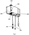
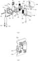
- the induction faucet further comprises: as shown in Fig. 2 , Fig. 3 and Fig. 4 , an induction control box 200.
- the control program, the control circuit board 207, the switch 215, the power supply and the indicator light 216 are arranged in the induction control box 200, the surface of the induction control box is provided with a flexible rubber plug 205, and the flexible rubber plug 205 is arranged at a position corresponding to the outside of the switch 215 and the indicator light 216.
- the faucet comprises:
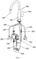
- the mixed water outlet conduit comprises a mixed water outlet hose 108 whose one end is disposed in fluid communication with the water outlet end of the mechanical handle 103, and a mixed water delivery hose 109 whose one end is disposed in fluid communication with the spout 101, an input end of the solenoid valve 206 is disposed in fluid communication with the other end of the mixed water outlet hose 108, and an output end of the solenoid valve 206 is disposed in fluid communication with the other end of the mixed water delivery hose 109. Therefore, a complete water path is realized.
- the induction control box 200 comprises the switch 215.
- a signal line 201 is electrically connected to a sensor 102 and a control circuit board 207; and a power line 202 is electrically connected to the control circuit board 207.
- a flexible rubber plug 205 is provided on the surface of the induction control box 200.
- the functional switch 215 can realize manual or automatic mode switch. When dialed up, it is in manual mode; when dialed down, it is in automatic mode.
- the manual mode is to completely use the faucet mechanical handle to control the on and off of the water supply
- the automatic mode is to use the infrared induction method to control the on and off of the water supply.
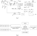
- the induction control box 200 comprises the control circuit board 207, whose circuit principle diagram is described in Fig.5 .
- the control circuit board adopts a three-stage mode for detecting the voltage. The first stage is that a battery supplies a normal working voltage (the voltage of the battery is 4.7-6 V), the second stage is that the battery supplies an insufficient voltage (the voltage of the battery is 4.5-4.7 V, and LED 1 is in a prompting mode by slowly flashing red light), and the third stage is that the battery is dead (the voltage of the battery is below 4.5V, the LED 1 is in another prompting mode by quickly flashing red light). As shown in Fig.
- an upper end of a resistor R6 is connected to a positive electrode of the battery; the resistors R6 and a resistor R9 form a voltage divider circuit to detect the voltage supplied by the battery, and a detected voltage is sent to a single chip microcomputer U2 for analysis and processing.
- the comparations with the voltage thresholds are performed in three stages by the algorithm.
- the LED 1 corresponds to the indicator light 216 shown in Fig. 4 .
- the slowly flashing red light is initially set to flash once per second, and the quickly flashing red light is initially set to flash twice per second.
- the flexible rubber plug 205 is made of translucent materials, which can not only realize the waterproof function to prevent water from seeping into the shell from the surface of the shell, but also makes it possible to see the inside LED with a state of flashing red light.
- the induction control box 200 also comprises a lower cover 209, a hanging board 210, sliding wheels 217, a bending plate 208 that is used to fix a solenoid valve 206, screws 211 used to lock the bending plate 208, screws 213 used to lock the sliding wheels 217, screws 212 used to lock the lower cover 209, and screws 214 used for fixing the hanging board 210.
- the sliding wheels 217 is used for fixing the induction control box 200 by inserting into an macrohole of the hanging board 210 and pushing sideways.
- the sensor 102 is an infrared sensor (may be other sensors), which is electrically connected with the induction control box 200 through a signal line 201.
- a battery box 300 can be loaded with four AA batteries 301, which are electrically connected to the induction control box 200 through a power line 202, and used to supply power to the whole machine.
- a hook-and-loop fastener 400 has two pieces separated, one piece is attached to a side of the battery box 300, and the other piece is attached to a side of the induction control box 200. After the two pieces are pressed together, the battery box 300 can be fixed on a side of the induction control box 200.
- the senor 102 is a far-infrared sensor.
- the induction control box 200 and an infrared induction faucet 100 will be hereinafter described.
- the induction control box 200 is connected with the infrared induction faucet 100, and mainly realizes automatic induction control of the on-off state of water supply through the sensor 102 arranged on the infrared induction faucet 100.
- a faucet body 100, a spout 101, an infrared sensor 102, a mechanical handle 103 with the switching function and the temperature adjusting function, a hot water inlet hose 104, a cold water inlet hose 105, a hot water inlet angle valve 106, and a cold water inlet angle valve 107 are shown. If the automatic induction water supply function will be used, the mechanical handle 103 must be fully opened firstly.
- the signal line 201 is electrically connected to the sensor 102 and the power line 202 is electrically connected to the control circuit board 207.
- a flexible rubber plug 205 is provided on the surface of the induction control box 200.
- the functional switch 215 can realize manual or automatic mode switch. When dialed up, it is in manual mode; when dialed down, it is in automatic mode.
- the manual mode is to completely use the faucet mechanical handle to control the on and off of the water supply
- the automatic mode is to use the infrared induction method to control the on and off of the water supply (i.e., an automatic mode realized by the solenoid valve 206 and the sensor 102).
- the induction control box 200 comprises the control circuit board 207, whose circuit principle diagram is described in Fig.5 .
- the control circuit board adopts a three-stage mode for detecting the voltage. The first stage is that a battery supplies a normal working voltage (the voltage of the battery is 4.7-6 V), the second stage is that the battery supplies an insufficient voltage (the voltage of the battery is 4.5-4.7 V, and LED 1 is in a prompting mode by slowly flashing red light), and the third stage is that the battery is dead (the voltage of the battery is below 4.5V, the LED 1 is in another prompting mode by quickly flashing red light). As shown in Fig.
- an upper end of a resistor R6 is connected to a positive electrode of the battery; the resistors R6 and a resistor R9 form a voltage divider circuit to detect the voltage supplied by the battery, and a detected voltage is sent to a single chip microcomputer U2 for analysis and processing.
- the comparations with the voltage thresholds are performed in three stages by the algorithm.
- the LED 1 corresponds to the indicator light 216 shown in Fig. 4 .
- the slowly flashing red light is initially set to flash once per second, and the quickly flashing red light is initially set to flash twice per second.
- the flexible rubber plug 205 is made of translucent materials, which can not only realize the waterproof function to prevent water from seeping into the shell from the surface of the shell, but also makes it possible to see the inside LED with a state of flashing red light.
- the induction control box 200 also comprises a lower cover 209, a hanging board 210, sliding wheels 217, a bending plate 208 that is used to fix a solenoid valve 206, screws 211 used to lock the bending plate 208, screws 213 used to lock the sliding wheels 217, screws 212 used to lock the lower cover 209, and screws 214 used for fixing the hanging board 210.
- the sliding wheels 217 is used for fixing the induction control box 200 by inserting into an macrohole of the hanging board 210 and pushing sideways.
- the sensor 102 is an infrared sensor (may be other sensors), which is electrically connected with the induction control box 200 through a signal line 201.
- a battery box 300 can be loaded with four AA batteries 301, which are electrically connected to the induction control box 200 through a power line 202, and used to supply power to the whole machine.
- a hook-and-loop fastener 400 has two pieces separated, one piece is attached to a side of the battery box 300, and the other piece is attached to a side of the induction control box 200. After the two pieces are pressed together, the battery box 300 can be fixed on a side of the induction control box 200.
- the induction control box 200 of the invention comprising the switch for switching between manual switch mode/automatic switch mode is used to control the on-off state of the faucet.
- the induction control box 200 adopts a three-stage mode for detecting the voltage and may slowly flash red light or quickly flash red light.
- the battery box can be fixed on a side of the induction control box by a hook-and-loop fastener.
- the induction control box may be fixed by the hanging board.
Landscapes
- Engineering & Computer Science (AREA)
- General Engineering & Computer Science (AREA)
- Health & Medical Sciences (AREA)
- Life Sciences & Earth Sciences (AREA)
- Hydrology & Water Resources (AREA)
- Public Health (AREA)
- Water Supply & Treatment (AREA)
- Mechanical Engineering (AREA)
- Physics & Mathematics (AREA)
- Electromagnetism (AREA)
- Domestic Plumbing Installations (AREA)
- Magnetically Actuated Valves (AREA)
Claims (6)
- Robinet d'induction qui comprend :un robinet, qui a un mode de commutation automatique sans contact et un mode de commutation manuel avec la mise en contact d'une poignée mécanique (103) ;un capteur (102), qui est agencé sur le robinet ;une vanne électromagnétique (206), qui est agencée sur un trajet de sortie d'eau du robinet, et qui est raccordée au capteur (102), dans lequel lorsque le capteur (102) et la vanne électromagnétique (206) sont dans un état de fonctionnement, le robinet fournit de l'eau par le mode de commutation automatique ;un commutateur (215), le commutateur (215) étant conçu pour commuter le robinet du mode de commutation automatique au mode de commutation manuel lorsque le capteur (102) et/ou la vanne électromagnétique (206) sont détectés comme n'étant pas dans l'état de fonctionnement ;une alimentation électrique, qui est respectivement connectée électriquement au capteur (102) et à la vanne électromagnétique (206) ;une carte de circuit de commande (207), qui est connectée à l'alimentation électrique ;un programme de commande, qui est respectivement connecté à la carte de circuit de commande (207), à la vanne électromagnétique (206) et au capteur (102), et est configuré pour déterminer si la vanne électromagnétique (206) et/ou le capteur (102) sont dans l'état de fonctionnement en détectant si une tension suffisante est fournie pour la vanne électromagnétique (206) et/ou le capteur (102) par l'alimentation électrique, dans lequel lorsque la tension est détectée comme étant inférieure à un seuil de tension prédéfini, le programme de commande commande le commutateur (215) pour commuter de l'état marche-arrêt du conduit d'écoulement de liquide vers le mode de fonctionnement commandé par une vanne mécanique ;un voyant lumineux (216), qui est connecté au programme de commande, et qui est configuré pour clignoter lorsqu'une tension fournie par l'alimentation électrique détectée par le programme de commande est insuffisante pour maintenir l'état de fonctionnement de la vanne électromagnétique (206) et/ou du capteur (102) ;dans lequel le programme de commande adopte un mode triphasé permettant de détecter la tension, dans lequel la première phase indique qu'une batterie fournit une tension de fonctionnement normale lorsque la tension de la batterie est de 4,7 à 6 V, la deuxième phase indique que la batterie fournit une tension insuffisante lorsque la tension de la batterie est de 4,5 à 4,7 V, le voyant lumineux (216) étant dans un mode de signalement en faisant clignoter lentement une lumière rouge, et la troisième phase indique que la batterie est déchargée lorsque la tension de la batterie est inférieure à 4,5 V, le voyant lumineux étant dans un mode de signalement en faisant clignoter rapidement une lumière rouge.
- Robinet d'induction selon la revendication 1, dans lequel l'état marche-arrêt du robinet peut être commuté automatiquement ou manuellement par le commutateur (215).
- Robinet à induction selon la revendication 1, comprenant en outre :
une boîte de commande d'induction (200), dans laquelle le programme de commande, la carte de circuit de commande (207), le commutateur (215), l'alimentation électrique et le voyant lumineux (216) sont agencés dans la boîte de commande d'induction (200), la surface de la boîte de commande d'induction (200) est pourvue d'un bouchon en caoutchouc flexible (205), et le bouchon en caoutchouc flexible (205) est agencé au niveau d'une position correspondant à l'extérieur du commutateur (215) et du voyant lumineux (216). - Robinet à induction selon la revendication 1, dans lequel le robinet comprend :un corps de robinet (100), qui comprend un bec (101) et la poignée mécanique (103), dans lequel le capteur (102) est agencé au niveau d'un côté avant du corps de robinet (100), une extrémité d'entrée d'eau du corps de robinet (100) est respectivement disposée en communication fluidique avec un tuyau d'entrée d'eau chaude (104) et un tuyau d'entrée d'eau froide (105), le tuyau d'entrée d'eau chaude (104) et le tuyau d'entrée d'eau froide (105) sont mélangés au niveau de la poignée mécanique (103) pour fournir de l'eau mélangée, une extrémité de sortie d'eau de la poignée mécanique (103) est disposée en communication fluidique avec le bec (101) à travers un conduit de sortie d'eau mélangée, et la vanne électromagnétique (206) est agencée au niveau du conduit de sortie d'eau mélangée ; etlorsque le robinet fournit de l'eau dans le mode de commutation automatique sans contact, la poignée mécanique (103) est dans un état de mise en marche.
- Robinet d'induction selon la revendication 4, dans lequel le conduit de sortie d'eau mélangée comprend un tuyau de sortie d'eau mélangée (108) dont une extrémité est disposée en communication fluidique avec l'extrémité de sortie d'eau de la poignée mécanique (103), et un tuyau de distribution d'eau mixte (109) dont une extrémité est disposée en communication fluidique avec le bec (101), dans lequel une extrémité d'entrée de la vanne électromagnétique (206) est disposée en communication fluidique avec l'autre extrémité du tuyau de sortie d'eau mélangée (108), et une extrémité de sortie de la vanne électromagnétique (106) est disposée en communication fluidique avec l'autre extrémité du tuyau de distribution d'eau mélangée (109).
- Robinet d'induction selon la revendication 1, dans lequel le capteur (102) est un capteur infrarouge lointain.
Applications Claiming Priority (1)
| Application Number | Priority Date | Filing Date | Title |
|---|---|---|---|
| CN202110394779.XA CN113063021A (zh) | 2021-04-13 | 2021-04-13 | 切换开关、带切换开关的感应控制盒和感应龙头 |
Publications (2)
| Publication Number | Publication Date |
|---|---|
| EP4074902A1 EP4074902A1 (fr) | 2022-10-19 |
| EP4074902B1 true EP4074902B1 (fr) | 2023-05-10 |
Family
ID=76566697
Family Applications (1)
| Application Number | Title | Priority Date | Filing Date |
|---|---|---|---|
| EP21185804.8A Active EP4074902B1 (fr) | 2021-04-13 | 2021-07-15 | Commutateur, boîtier de commande à induction comprenant celui-ci et robinet à induction |
Country Status (3)
| Country | Link |
|---|---|
| US (1) | US11619318B2 (fr) |
| EP (1) | EP4074902B1 (fr) |
| CN (1) | CN113063021A (fr) |
Families Citing this family (4)
| Publication number | Priority date | Publication date | Assignee | Title |
|---|---|---|---|---|
| US11802397B2 (en) * | 2021-12-10 | 2023-10-31 | Xiamen Forbetter Sanitary Ware Co., Ltd. | Dual-handle and dual-control faucet |
| US12055237B2 (en) * | 2022-01-20 | 2024-08-06 | Ncip Inc. | Sensor-operated kitchen faucet |
| JP7833297B2 (ja) * | 2022-01-28 | 2026-03-19 | 株式会社Kvk | アダプタ、及び、センサー式水栓を手動式水栓にする方法 |
| CN119594208B (zh) * | 2024-12-25 | 2025-11-21 | 广州海鸥住宅工业股份有限公司 | 智能双控龙头及其控制方法 |
Family Cites Families (18)
| Publication number | Priority date | Publication date | Assignee | Title |
|---|---|---|---|---|
| US5099210A (en) * | 1990-06-01 | 1992-03-24 | Koss Corporation | Battery status indicator |
| US7150293B2 (en) * | 2004-01-12 | 2006-12-19 | Masco Corporation Of Indiana | Multi-mode hands free automatic faucet |
| US6962168B2 (en) * | 2004-01-14 | 2005-11-08 | Masco Corporation Of Indiana | Capacitive touch on/off control for an automatic residential faucet |
| US7357370B2 (en) * | 2006-05-02 | 2008-04-15 | Jan Sun Chen | Detent apparatus for water temperature regulation of induction faucets |
| EP1876305A1 (fr) * | 2006-07-07 | 2008-01-09 | Hsiang Hung Wang | Robinet mélangeur avec commutation de la commande automatique à manuelle |
| CN101418910B (zh) * | 2008-11-28 | 2011-05-25 | 同济大学 | 车载高压储氢瓶用一体式瓶阀 |
| US8561626B2 (en) * | 2010-04-20 | 2013-10-22 | Masco Corporation Of Indiana | Capacitive sensing system and method for operating a faucet |
| ES2394694B1 (es) * | 2010-05-17 | 2013-10-30 | Roca Sanitario, S.A. | Griferia electronica |
| CN203248812U (zh) * | 2013-04-22 | 2013-10-23 | 路达(厦门)工业有限公司 | 智能感应水龙头 |
| CN203248766U (zh) * | 2013-04-22 | 2013-10-23 | 路达(厦门)工业有限公司 | 双控智能感应水龙头 |
| CN103363177B (zh) * | 2013-07-19 | 2015-09-09 | 应俊 | 手动与感应一体式智能水龙头 |
| CN203627981U (zh) * | 2013-11-08 | 2014-06-04 | 珠海爱迪生节能科技有限公司 | 一种水龙头通用型电容式触碰感应开关组件 |
| CN206054822U (zh) * | 2016-09-18 | 2017-03-29 | 厦门市欧立通电子科技开发有限公司 | 智能触摸感应厨房龙头 |
| CN107228222B (zh) * | 2017-03-29 | 2024-03-12 | 厦门建霖健康家居股份有限公司 | 一种集成式开关装置 |
| JP6966880B2 (ja) * | 2017-06-22 | 2021-11-17 | 株式会社ハウステック | 自動水栓のモード切替操作装置 |
| CN208900800U (zh) * | 2018-08-27 | 2019-05-24 | 广东华艺卫浴实业有限公司 | 手动电子感应一体化的水龙头装置 |
| CN210859989U (zh) * | 2019-01-31 | 2020-06-26 | 厦门建霖健康家居股份有限公司 | 一种带切换开关的龙头 |
| CN212298549U (zh) * | 2020-06-22 | 2021-01-05 | 如皋瀚氢新能源科技有限公司 | 一种集成式减压瓶阀 |
-
2021
- 2021-04-13 CN CN202110394779.XA patent/CN113063021A/zh active Pending
- 2021-06-30 US US17/363,112 patent/US11619318B2/en active Active
- 2021-07-15 EP EP21185804.8A patent/EP4074902B1/fr active Active
Also Published As
| Publication number | Publication date |
|---|---|
| CN113063021A (zh) | 2021-07-02 |
| US11619318B2 (en) | 2023-04-04 |
| US20220325817A1 (en) | 2022-10-13 |
| EP4074902A1 (fr) | 2022-10-19 |
Similar Documents
| Publication | Publication Date | Title |
|---|---|---|
| US11619318B2 (en) | Switch, induction control box comprising the same, and induction faucet | |
| US8127782B2 (en) | Multi-mode hands free automatic faucet | |
| CA2902745C (fr) | Robinet a detection capacitive et ultrasonore | |
| CN102844501B (zh) | 具有电容式传感系统的电子龙头以及用于所述电子龙头的方法 | |
| US20130048090A1 (en) | Human body sensitive touch-controlled water outlet device and control method thereof | |
| CN104197077B (zh) | 一种陶瓷面盆水龙头开关组件 | |
| CN206280569U (zh) | 一种双红外线感应厨房水龙头 | |
| US10941548B2 (en) | Faucet including passive and active sensing | |
| US11802396B2 (en) | Hybrid faucet assembly | |
| US8863774B2 (en) | Water flow controller for faucet | |
| CN116201945A (zh) | 一种智能控水龙头 | |
| JP2003105817A (ja) | 給水制御装置 | |
| CN219529960U (zh) | 一种智能控水龙头 | |
| CN210034527U (zh) | 一种水龙头 | |
| US20190032311A1 (en) | Pressure sensitive touch electronic faucet | |
| JP2010065463A (ja) | 自動水栓システム | |
| KR20120006041U (ko) | 감지 및 터치 혼용 자동수전 | |
| CN206280570U (zh) | 一种触摸式感应抽拉式厨房水龙头 | |
| JP2009108490A (ja) | 自動水栓 | |
| JP5077818B2 (ja) | 自動水栓 | |
| KR20180001794U (ko) | 풋 터치 스위치와 핸드 터치 스위치를 동시에 갖는 전자밸브 개폐 싱크대 수전구 | |
| JP5908690B2 (ja) | 水栓装置 | |
| CN117450312A (zh) | 水龙头 | |
| CN203948750U (zh) | 一种陶瓷面盆水龙头开关组件 | |
| CN212564634U (zh) | 一种组合龙头 |
Legal Events
| Date | Code | Title | Description |
|---|---|---|---|
| STAA | Information on the status of an ep patent application or granted ep patent |
Free format text: STATUS: EXAMINATION IS IN PROGRESS |
|
| PUAI | Public reference made under article 153(3) epc to a published international application that has entered the european phase |
Free format text: ORIGINAL CODE: 0009012 |
|
| 17P | Request for examination filed |
Effective date: 20210715 |
|
| AK | Designated contracting states |
Kind code of ref document: A1 Designated state(s): AL AT BE BG CH CY CZ DE DK EE ES FI FR GB GR HR HU IE IS IT LI LT LU LV MC MK MT NL NO PL PT RO RS SE SI SK SM TR |
|
| GRAP | Despatch of communication of intention to grant a patent |
Free format text: ORIGINAL CODE: EPIDOSNIGR1 |
|
| STAA | Information on the status of an ep patent application or granted ep patent |
Free format text: STATUS: GRANT OF PATENT IS INTENDED |
|
| GRAS | Grant fee paid |
Free format text: ORIGINAL CODE: EPIDOSNIGR3 |
|
| GRAA | (expected) grant |
Free format text: ORIGINAL CODE: 0009210 |
|
| STAA | Information on the status of an ep patent application or granted ep patent |
Free format text: STATUS: THE PATENT HAS BEEN GRANTED |
|
| INTG | Intention to grant announced |
Effective date: 20230316 |
|
| AK | Designated contracting states |
Kind code of ref document: B1 Designated state(s): AL AT BE BG CH CY CZ DE DK EE ES FI FR GB GR HR HU IE IS IT LI LT LU LV MC MK MT NL NO PL PT RO RS SE SI SK SM TR |
|
| REG | Reference to a national code |
Ref country code: GB Ref legal event code: FG4D |
|
| REG | Reference to a national code |
Ref country code: AT Ref legal event code: REF Ref document number: 1566802 Country of ref document: AT Kind code of ref document: T Effective date: 20230515 Ref country code: CH Ref legal event code: EP |
|
| REG | Reference to a national code |
Ref country code: DE Ref legal event code: R096 Ref document number: 602021002279 Country of ref document: DE |
|
| REG | Reference to a national code |
Ref country code: IE Ref legal event code: FG4D |
|
| P01 | Opt-out of the competence of the unified patent court (upc) registered |
Effective date: 20230330 |
|
| REG | Reference to a national code |
Ref country code: LT Ref legal event code: MG9D |
|
| REG | Reference to a national code |
Ref country code: NL Ref legal event code: MP Effective date: 20230510 |
|
| REG | Reference to a national code |
Ref country code: AT Ref legal event code: MK05 Ref document number: 1566802 Country of ref document: AT Kind code of ref document: T Effective date: 20230510 |
|
| PG25 | Lapsed in a contracting state [announced via postgrant information from national office to epo] |
Ref country code: SE Free format text: LAPSE BECAUSE OF FAILURE TO SUBMIT A TRANSLATION OF THE DESCRIPTION OR TO PAY THE FEE WITHIN THE PRESCRIBED TIME-LIMIT Effective date: 20230510 Ref country code: PT Free format text: LAPSE BECAUSE OF FAILURE TO SUBMIT A TRANSLATION OF THE DESCRIPTION OR TO PAY THE FEE WITHIN THE PRESCRIBED TIME-LIMIT Effective date: 20230911 Ref country code: NO Free format text: LAPSE BECAUSE OF FAILURE TO SUBMIT A TRANSLATION OF THE DESCRIPTION OR TO PAY THE FEE WITHIN THE PRESCRIBED TIME-LIMIT Effective date: 20230810 Ref country code: NL Free format text: LAPSE BECAUSE OF FAILURE TO SUBMIT A TRANSLATION OF THE DESCRIPTION OR TO PAY THE FEE WITHIN THE PRESCRIBED TIME-LIMIT Effective date: 20230510 Ref country code: ES Free format text: LAPSE BECAUSE OF FAILURE TO SUBMIT A TRANSLATION OF THE DESCRIPTION OR TO PAY THE FEE WITHIN THE PRESCRIBED TIME-LIMIT Effective date: 20230510 Ref country code: AT Free format text: LAPSE BECAUSE OF FAILURE TO SUBMIT A TRANSLATION OF THE DESCRIPTION OR TO PAY THE FEE WITHIN THE PRESCRIBED TIME-LIMIT Effective date: 20230510 |
|
| PG25 | Lapsed in a contracting state [announced via postgrant information from national office to epo] |
Ref country code: RS Free format text: LAPSE BECAUSE OF FAILURE TO SUBMIT A TRANSLATION OF THE DESCRIPTION OR TO PAY THE FEE WITHIN THE PRESCRIBED TIME-LIMIT Effective date: 20230510 Ref country code: PL Free format text: LAPSE BECAUSE OF FAILURE TO SUBMIT A TRANSLATION OF THE DESCRIPTION OR TO PAY THE FEE WITHIN THE PRESCRIBED TIME-LIMIT Effective date: 20230510 Ref country code: LV Free format text: LAPSE BECAUSE OF FAILURE TO SUBMIT A TRANSLATION OF THE DESCRIPTION OR TO PAY THE FEE WITHIN THE PRESCRIBED TIME-LIMIT Effective date: 20230510 Ref country code: LT Free format text: LAPSE BECAUSE OF FAILURE TO SUBMIT A TRANSLATION OF THE DESCRIPTION OR TO PAY THE FEE WITHIN THE PRESCRIBED TIME-LIMIT Effective date: 20230510 Ref country code: IS Free format text: LAPSE BECAUSE OF FAILURE TO SUBMIT A TRANSLATION OF THE DESCRIPTION OR TO PAY THE FEE WITHIN THE PRESCRIBED TIME-LIMIT Effective date: 20230910 Ref country code: HR Free format text: LAPSE BECAUSE OF FAILURE TO SUBMIT A TRANSLATION OF THE DESCRIPTION OR TO PAY THE FEE WITHIN THE PRESCRIBED TIME-LIMIT Effective date: 20230510 Ref country code: GR Free format text: LAPSE BECAUSE OF FAILURE TO SUBMIT A TRANSLATION OF THE DESCRIPTION OR TO PAY THE FEE WITHIN THE PRESCRIBED TIME-LIMIT Effective date: 20230811 |
|
| PG25 | Lapsed in a contracting state [announced via postgrant information from national office to epo] |
Ref country code: FI Free format text: LAPSE BECAUSE OF FAILURE TO SUBMIT A TRANSLATION OF THE DESCRIPTION OR TO PAY THE FEE WITHIN THE PRESCRIBED TIME-LIMIT Effective date: 20230510 |
|
| PG25 | Lapsed in a contracting state [announced via postgrant information from national office to epo] |
Ref country code: SK Free format text: LAPSE BECAUSE OF FAILURE TO SUBMIT A TRANSLATION OF THE DESCRIPTION OR TO PAY THE FEE WITHIN THE PRESCRIBED TIME-LIMIT Effective date: 20230510 |
|
| PG25 | Lapsed in a contracting state [announced via postgrant information from national office to epo] |
Ref country code: SM Free format text: LAPSE BECAUSE OF FAILURE TO SUBMIT A TRANSLATION OF THE DESCRIPTION OR TO PAY THE FEE WITHIN THE PRESCRIBED TIME-LIMIT Effective date: 20230510 Ref country code: SK Free format text: LAPSE BECAUSE OF FAILURE TO SUBMIT A TRANSLATION OF THE DESCRIPTION OR TO PAY THE FEE WITHIN THE PRESCRIBED TIME-LIMIT Effective date: 20230510 Ref country code: RO Free format text: LAPSE BECAUSE OF FAILURE TO SUBMIT A TRANSLATION OF THE DESCRIPTION OR TO PAY THE FEE WITHIN THE PRESCRIBED TIME-LIMIT Effective date: 20230510 Ref country code: EE Free format text: LAPSE BECAUSE OF FAILURE TO SUBMIT A TRANSLATION OF THE DESCRIPTION OR TO PAY THE FEE WITHIN THE PRESCRIBED TIME-LIMIT Effective date: 20230510 Ref country code: DK Free format text: LAPSE BECAUSE OF FAILURE TO SUBMIT A TRANSLATION OF THE DESCRIPTION OR TO PAY THE FEE WITHIN THE PRESCRIBED TIME-LIMIT Effective date: 20230510 Ref country code: CZ Free format text: LAPSE BECAUSE OF FAILURE TO SUBMIT A TRANSLATION OF THE DESCRIPTION OR TO PAY THE FEE WITHIN THE PRESCRIBED TIME-LIMIT Effective date: 20230510 |
|
| REG | Reference to a national code |
Ref country code: DE Ref legal event code: R097 Ref document number: 602021002279 Country of ref document: DE |
|
| PG25 | Lapsed in a contracting state [announced via postgrant information from national office to epo] |
Ref country code: MC Free format text: LAPSE BECAUSE OF FAILURE TO SUBMIT A TRANSLATION OF THE DESCRIPTION OR TO PAY THE FEE WITHIN THE PRESCRIBED TIME-LIMIT Effective date: 20230510 |
|
| PG25 | Lapsed in a contracting state [announced via postgrant information from national office to epo] |
Ref country code: MC Free format text: LAPSE BECAUSE OF FAILURE TO SUBMIT A TRANSLATION OF THE DESCRIPTION OR TO PAY THE FEE WITHIN THE PRESCRIBED TIME-LIMIT Effective date: 20230510 |
|
| PLBE | No opposition filed within time limit |
Free format text: ORIGINAL CODE: 0009261 |
|
| STAA | Information on the status of an ep patent application or granted ep patent |
Free format text: STATUS: NO OPPOSITION FILED WITHIN TIME LIMIT |
|
| REG | Reference to a national code |
Ref country code: BE Ref legal event code: MM Effective date: 20230731 |
|
| PG25 | Lapsed in a contracting state [announced via postgrant information from national office to epo] |
Ref country code: LU Free format text: LAPSE BECAUSE OF NON-PAYMENT OF DUE FEES Effective date: 20230715 |
|
| PG25 | Lapsed in a contracting state [announced via postgrant information from national office to epo] |
Ref country code: LU Free format text: LAPSE BECAUSE OF NON-PAYMENT OF DUE FEES Effective date: 20230715 |
|
| 26N | No opposition filed |
Effective date: 20240213 |
|
| REG | Reference to a national code |
Ref country code: IE Ref legal event code: MM4A |
|
| PG25 | Lapsed in a contracting state [announced via postgrant information from national office to epo] |
Ref country code: SI Free format text: LAPSE BECAUSE OF FAILURE TO SUBMIT A TRANSLATION OF THE DESCRIPTION OR TO PAY THE FEE WITHIN THE PRESCRIBED TIME-LIMIT Effective date: 20230510 |
|
| PG25 | Lapsed in a contracting state [announced via postgrant information from national office to epo] |
Ref country code: SI Free format text: LAPSE BECAUSE OF FAILURE TO SUBMIT A TRANSLATION OF THE DESCRIPTION OR TO PAY THE FEE WITHIN THE PRESCRIBED TIME-LIMIT Effective date: 20230510 Ref country code: IT Free format text: LAPSE BECAUSE OF FAILURE TO SUBMIT A TRANSLATION OF THE DESCRIPTION OR TO PAY THE FEE WITHIN THE PRESCRIBED TIME-LIMIT Effective date: 20230510 Ref country code: BE Free format text: LAPSE BECAUSE OF NON-PAYMENT OF DUE FEES Effective date: 20230731 |
|
| PG25 | Lapsed in a contracting state [announced via postgrant information from national office to epo] |
Ref country code: IE Free format text: LAPSE BECAUSE OF NON-PAYMENT OF DUE FEES Effective date: 20230715 |
|
| PG25 | Lapsed in a contracting state [announced via postgrant information from national office to epo] |
Ref country code: IE Free format text: LAPSE BECAUSE OF NON-PAYMENT OF DUE FEES Effective date: 20230715 |
|
| PG25 | Lapsed in a contracting state [announced via postgrant information from national office to epo] |
Ref country code: BG Free format text: LAPSE BECAUSE OF FAILURE TO SUBMIT A TRANSLATION OF THE DESCRIPTION OR TO PAY THE FEE WITHIN THE PRESCRIBED TIME-LIMIT Effective date: 20230510 |
|
| PG25 | Lapsed in a contracting state [announced via postgrant information from national office to epo] |
Ref country code: BG Free format text: LAPSE BECAUSE OF FAILURE TO SUBMIT A TRANSLATION OF THE DESCRIPTION OR TO PAY THE FEE WITHIN THE PRESCRIBED TIME-LIMIT Effective date: 20230510 |
|
| REG | Reference to a national code |
Ref country code: CH Ref legal event code: PL |
|
| PG25 | Lapsed in a contracting state [announced via postgrant information from national office to epo] |
Ref country code: CH Free format text: LAPSE BECAUSE OF NON-PAYMENT OF DUE FEES Effective date: 20240731 |
|
| PGFP | Annual fee paid to national office [announced via postgrant information from national office to epo] |
Ref country code: GB Payment date: 20250626 Year of fee payment: 5 |
|
| PGFP | Annual fee paid to national office [announced via postgrant information from national office to epo] |
Ref country code: FR Payment date: 20250626 Year of fee payment: 5 |
|
| PG25 | Lapsed in a contracting state [announced via postgrant information from national office to epo] |
Ref country code: CY Free format text: LAPSE BECAUSE OF FAILURE TO SUBMIT A TRANSLATION OF THE DESCRIPTION OR TO PAY THE FEE WITHIN THE PRESCRIBED TIME-LIMIT; INVALID AB INITIO Effective date: 20210715 |
|
| PG25 | Lapsed in a contracting state [announced via postgrant information from national office to epo] |
Ref country code: HU Free format text: LAPSE BECAUSE OF FAILURE TO SUBMIT A TRANSLATION OF THE DESCRIPTION OR TO PAY THE FEE WITHIN THE PRESCRIBED TIME-LIMIT; INVALID AB INITIO Effective date: 20210715 |
|
| PGFP | Annual fee paid to national office [announced via postgrant information from national office to epo] |
Ref country code: DE Payment date: 20250627 Year of fee payment: 5 |
|
| PG25 | Lapsed in a contracting state [announced via postgrant information from national office to epo] |
Ref country code: TR Free format text: LAPSE BECAUSE OF FAILURE TO SUBMIT A TRANSLATION OF THE DESCRIPTION OR TO PAY THE FEE WITHIN THE PRESCRIBED TIME-LIMIT Effective date: 20230510 |