EP4074930A1 - Kraftfahrzeugtürschloss und kraftfahrzeugtür - Google Patents
Kraftfahrzeugtürschloss und kraftfahrzeugtür Download PDFInfo
- Publication number
- EP4074930A1 EP4074930A1 EP21193599.4A EP21193599A EP4074930A1 EP 4074930 A1 EP4074930 A1 EP 4074930A1 EP 21193599 A EP21193599 A EP 21193599A EP 4074930 A1 EP4074930 A1 EP 4074930A1
- Authority
- EP
- European Patent Office
- Prior art keywords
- opening
- safety
- linkage board
- board
- outward
- Prior art date
- Legal status (The legal status is an assumption and is not a legal conclusion. Google has not performed a legal analysis and makes no representation as to the accuracy of the status listed.)
- Granted
Links
Images





Classifications
-
- E—FIXED CONSTRUCTIONS
- E05—LOCKS; KEYS; WINDOW OR DOOR FITTINGS; SAFES
- E05B—LOCKS; ACCESSORIES THEREFOR; HANDCUFFS
- E05B83/00—Vehicle locks specially adapted for particular types of wing or vehicle
- E05B83/36—Locks for passenger or like doors
- E05B83/44—Locks for passenger or like doors for recreational vehicles, e.g. caravans or camper vans
-
- E—FIXED CONSTRUCTIONS
- E05—LOCKS; KEYS; WINDOW OR DOOR FITTINGS; SAFES
- E05B—LOCKS; ACCESSORIES THEREFOR; HANDCUFFS
- E05B83/00—Vehicle locks specially adapted for particular types of wing or vehicle
- E05B83/36—Locks for passenger or like doors
-
- E—FIXED CONSTRUCTIONS
- E05—LOCKS; KEYS; WINDOW OR DOOR FITTINGS; SAFES
- E05B—LOCKS; ACCESSORIES THEREFOR; HANDCUFFS
- E05B77/00—Vehicle locks characterised by special functions or purposes
- E05B77/22—Functions related to actuation of locks from the passenger compartment of the vehicle
- E05B77/24—Functions related to actuation of locks from the passenger compartment of the vehicle preventing use of an inner door handle, sill button, lock knob or the like
-
- E—FIXED CONSTRUCTIONS
- E05—LOCKS; KEYS; WINDOW OR DOOR FITTINGS; SAFES
- E05B—LOCKS; ACCESSORIES THEREFOR; HANDCUFFS
- E05B77/00—Vehicle locks characterised by special functions or purposes
- E05B77/22—Functions related to actuation of locks from the passenger compartment of the vehicle
- E05B77/24—Functions related to actuation of locks from the passenger compartment of the vehicle preventing use of an inner door handle, sill button, lock knob or the like
- E05B77/26—Functions related to actuation of locks from the passenger compartment of the vehicle preventing use of an inner door handle, sill button, lock knob or the like specially adapted for child safety
-
- E—FIXED CONSTRUCTIONS
- E05—LOCKS; KEYS; WINDOW OR DOOR FITTINGS; SAFES
- E05B—LOCKS; ACCESSORIES THEREFOR; HANDCUFFS
- E05B79/00—Mounting or connecting vehicle locks or parts thereof
- E05B79/10—Connections between movable lock parts
- E05B79/20—Connections between movable lock parts using flexible connections, e.g. Bowden cables
-
- E—FIXED CONSTRUCTIONS
- E05—LOCKS; KEYS; WINDOW OR DOOR FITTINGS; SAFES
- E05B—LOCKS; ACCESSORIES THEREFOR; HANDCUFFS
- E05B79/00—Mounting or connecting vehicle locks or parts thereof
- E05B79/10—Connections between movable lock parts
- E05B79/22—Operative connections between handles, sill buttons or lock knobs and the lock unit
-
- E—FIXED CONSTRUCTIONS
- E05—LOCKS; KEYS; WINDOW OR DOOR FITTINGS; SAFES
- E05B—LOCKS; ACCESSORIES THEREFOR; HANDCUFFS
- E05B81/00—Power-actuated vehicle locks
- E05B81/02—Power-actuated vehicle locks characterised by the type of actuators used
- E05B81/04—Electrical
- E05B81/06—Electrical using rotary motors
-
- E—FIXED CONSTRUCTIONS
- E05—LOCKS; KEYS; WINDOW OR DOOR FITTINGS; SAFES
- E05B—LOCKS; ACCESSORIES THEREFOR; HANDCUFFS
- E05B85/00—Details of vehicle locks not provided for in groups E05B77/00 - E05B83/00
- E05B85/20—Bolts or detents
-
- E—FIXED CONSTRUCTIONS
- E05—LOCKS; KEYS; WINDOW OR DOOR FITTINGS; SAFES
- E05B—LOCKS; ACCESSORIES THEREFOR; HANDCUFFS
- E05B47/00—Operating or controlling locks or other fastening devices by electric or magnetic means
- E05B2047/0072—Operation
- E05B2047/0076—Current to lock only, i.e. "fail-safe"
-
- E—FIXED CONSTRUCTIONS
- E05—LOCKS; KEYS; WINDOW OR DOOR FITTINGS; SAFES
- E05B—LOCKS; ACCESSORIES THEREFOR; HANDCUFFS
- E05B77/00—Vehicle locks characterised by special functions or purposes
- E05B77/32—Vehicle locks characterised by special functions or purposes allowing simultaneous actuation of locking or unlocking elements and a handle, e.g. preventing interference between an unlocking and an unlatching action
Definitions
- the present disclosure belongs to the technical field of automobile manufacturing, and particularly to an automobile door lock and an automobile door.
- Automobile door locks are key structures of vehicles, and the automobile door locks mainly play a role in protecting safety to guarantee the safety of life and property.
- the present application provides an automobile door lock and an automobile door for solving the problems of complicated structure and large volume, and occupying a large installation space of an automobile door in the prior art.
- the present application provides an automobile door lock applied to an automobile door of a vehicle, particularly an automobile door lock of an automobile door of a recreational vehicle.
- the recreational vehicle often abbreviated as RV or named camper, caravan, mobile home, is a motor vehicle or trailer which includes living quarters designed for accommodation.
- the automobile door look includes an outward-opening handle assembly, an inward-opening handle assembly, a central structure assembly, and at least one lock body assembly.
- the central structure assembly is provided inside the automobile door and includes a transmission structure and a safety structure.
- safety shall express that the structure is safely (reliably) in the actually desired state, such as closed and opened.
- the state is fail-safe and situations that the door is closed or opened undesirably due to negligence of the user or for other reasons (children or thieves) can efficiently be prevented.
- the transmission structure includes a bottom board, an outward-opening linkage board, an inward-opening linkage board and an opening linkage board that are rotatably provided on the bottom board, wherein the outward-opening linkage board, the inward-opening linkage board and the opening linkage board are provided along a normal direction of the bottom board in sequence, the outward-opening linkage board is configured to be linked with the opening linkage board to rotate, and the inward-opening linkage board is configured to be linked with the outward-opening linkage board to rotate.
- the outward-opening linkage board is connected to the outward-opening handle assembly, the inward-opening linkage board is connected to the inward-opening handle assembly, and each lock body assembly is connected to the opening linkage board.
- the safety structure includes a safety swing arm mechanism, a safety actuator, and a safety linkage board, wherein the safety swing arm mechanism is provided on the opening linkage board, the safety swing arm mechanism includes a first position and a second position, the safety actuator and the safety linkage board are both provided on the bottom board, and the safety actuator drives the safety linkage board to rotate so as to drive the safety swing arm mechanism to switch between the first position and the second position.
- the safety swing arm mechanism In an initial state, the safety swing arm mechanism is located at the first position, and the opening linkage board and the outward-opening linkage board are in linkage cooperation; and when the safety linkage board drives the safety swing arm mechanism to switch to the second position, the linkage cooperation of the opening linkage board and the outward-opening linkage board is released, and the inward-opening linkage board abuts against the safety linkage board.
- the present application further provides an automobile door applied to a recreation vehicle and including the automobile door lock provided in the first aspect.
- the present application provides an automobile door lock and an automobile door
- the automobile door lock includes an outward-opening handle assembly, an inward-opening handle assembly, a central structure assembly, and at least one lock body assembly
- the central structure assembly is provided inside the automobile door and includes a transmission structure and a safety structure
- the transmission structure includes a bottom board, an outward-opening linkage board, inward-opening linkage board and an opening linkage board that are rotatably provided on the bottom board, the outward-opening linkage board, the inward-opening linkage board and the opening linkage board are provided along a normal direction of the bottom board in sequence, the outward-opening linkage board is configured to be linked with the opening linkage board to rotate, the inward-opening linkage board is configured to be linked with the outward-opening linkage board to rotate, the outward-opening linkage board is connected to the outward-opening handle assembly, the inward-opening linkage board is
- the automobile door lock According to the automobile door lock provided in the present application, integration of the outward-opening handle assembly, the inward-opening handle assembly and a safety function is realized by the central structure assembly, and thus the automobile door lock has a simpler overall structure, a compact structure and a small volume, and does not occupy an installation space.
- the lock in particular comprises a central structure assembly, a transmission structure, an outward-opening linkage board, an inward-opening linkage board and an opening linkage board as well as a safety structure as disclosed here.
- 100 central structural assembly; 110: transmission structure; 111: bottom board; 1110: central control rotating shaft; 1111: pin shaft; 1112: first limiting pin; 1113: groove; 1114: limiting bayonet; 112: outward-opening linkage board; 1120: L-shaped linkage slot; 1120a: first slot section; 1120b: second slot section; 1121: retaining bayonet; 113: inward-opening linkage board; 1130: rotating body part; 1131: toggling arm; 1132: safety toggling pin; 1133: driving arm; 1134: second long kidney-shaped hole; 114: opening linkage board; 1140: first long kidney-shaped hole; 1141: limiting hole; 114a: third stay wire component; 115: child lock structure; 1150: switch board; 1150a: third long kidney-shaped hole; 1150b: toggling rod; 1150c: second limiting pin; 1150d: hump; 1151: driving shaft: 1151a: first sliding shaft part; 1151b: driving part;
- orientations or position relationships indicated by the terms “center”, “longitudinal”, “transverse”, “length”, “width”, “thickness”, “upper”, “lower”, “front”, “rear”, “left”, “right”, “vertical”, “horizontal”, “top”, “bottom”, “inside”, “outside”, “clockwise”, “anticlockwise”, “axial”, “radial”, “circumferential”, etc. are based on orientations or position relationships shown in the drawings, these terms are only for the convenience of describing the present disclosure and simplifying the description, and do not indicate or imply that the device or element referred to must have a specific orientation or be constructed and operated in a specific orientation. Therefore, they should not be regarded as a limitation of the present disclosure.
- first and second are merely for the purpose of description, but should not be understood as indicating or implying relative importance or implicitly indicating the number of indicated technical features. Therefore, a feature defined as “first” or “second” may explicitly or implicitly include one or more of these features. In the description of the present disclosure, “multiple” means two or more, unless otherwise specifically defined.
- the terms “install”, “join”, “connect”, “fix”, etc. should be understood in a broad sense.
- it may be a fixed connection, a detachable connection, or integrated; it may be a mechanical connection or an electrical connection; it may be directly connected or indirectly connected through an intermediate medium, and it may be the internal communication of two components or the interaction relationship between two components.
- install may be a fixed connection, a detachable connection, or integrated; it may be a mechanical connection or an electrical connection; it may be directly connected or indirectly connected through an intermediate medium, and it may be the internal communication of two components or the interaction relationship between two components.
- first feature is "above” the second feature may be that the first feature is right above or obliquely above the second feature, or it merely means that the level of the first feature is higher than that of the second feature.
- first feature is "below” the second feature may be that the first feature is right below or obliquely below the second feature, or it merely means that the level of the first feature is lower than that of the second feature.
- the present embodiment provides an automobile door lock applied to an automobile door of a vehicle, wherein the vehicle includes a car or recreation vehicle, and the automobile door lock is configured to lock the automobile door and plays a role in protecting safety so as to guarantee the safety of life and property.
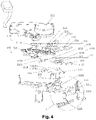
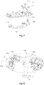
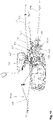
- the automobile door lock provided in the present embodiment includes an outward-opening handle assembly 300, an inward-opening handle assembly 200, a central structure assembly 100, and at least one lock body assembly 400, wherein the outward-opening handle assembly 300, the inward-opening handle assembly 200 and the lock body assembly 400 are all connected to the central structure assembly 100; the outward-opening handle assembly 300 controls the lock body assembly 400 via the central structure assembly 100 to perform an unlocking action; the inward-opening handle assembly 200 controls the lock body assembly 400 via the central structure assembly 100 to perform an unlocking action, and the outward-opening handle assembly 300 and the inward-opening handle assembly 200 do not interfere with each other.
- the above central structure assembly 100 is provided inside the automobile door and includes a transmission structure 110 and a safety structure 120.
- the transmission structure 110 includes a bottom board 111, an outward-opening linkage board 112, an inward-opening linkage board 113 and an opening linkage board 114 that are rotatably provided on the bottom board 111.
- the outward-opening linkage board 112, the inward-opening linkage board 113 and the opening linkage board 114 are provided along a normal direction of the bottom board 111 in sequence, that is, the inward-opening linkage board 113 is located between the outward-opening linkage board 112 and the opening linkage board 114, and the outward-opening linkage board 112 is closer to the bottom board 111 than the opening linkage board 114.
- the outward-opening linkage board 112 is configured to be linked with the opening linkage board 114 to rotate, and the inward-opening linkage board 113 is configured to be linked with the outward-opening linkage board 112 to rotate.
- the outward-opening linkage board 112 is connected to the outward-opening handle assembly 300, that is, the outward-opening handle assembly 300 controls the outward-opening linkage board 112 to rotate;
- the inward-opening linkage board 113 is connected to the inward-opening handle assembly 200, that is, the inward-opening handle assembly 200 controls the inward-opening linkage board 113 to rotate;
- each lock body assembly 400 is connected to the opening linkage board 114, that is, the opening linkage board 114 can control the lock body assembly 400 to perform an unlocking action.
- the bottom board 111 is provided with a central control rotating shaft 1110, wherein the outward-opening linkage board 112, the inward-opening linkage board 113 and the opening linkage board 114 are all provided on the central control rotating shaft 1110, that is, the outward-opening linkage board 112, the inward-opening linkage board 113 and the opening linkage board 114 can all rotate around an axis of the central control rotating shaft 1110.
- the safety structure 120 includes a safety swing arm mechanism 121, a safety actuator 122, and a safety linkage board 123, wherein the safety swing arm mechanism 121 is provided on the opening linkage board 114, the safety swing arm 122 and the safety linkage board 123 are both provided on the bottom board 111, and the safety actuator 122 drives the safety linkage board 123 to rotate so as to drive the safety swing arm mechanism 121 to switch between the first position and the second position.
- the safety swing arm mechanism 121 In an initial state, the safety swing arm mechanism 121 is located at the first position, that is, the safety arrangement is unlocked, the opening linkage board 114 and the outward-opening linkage board 112 are in linkage cooperation, that is, when the outward-opening linkage board 112 rotates, the opening linkage board 114 is driven to rotate together, and then the opening linkage board 114 drives the lock body assembly 400 to perform an unlocking action.
- the safety linkage board 123 can be pushed to rotate so as to release the restriction of the safety linkage board 123 on the safety swing arm mechanism 121, so that the safety swing arm mechanism 121 automatically switches back to the first position from the second position to unlock the safety arrangement. That is, when the safety arrangement is locked, driving the inward-opening linkage board 113 to rotate for the first time cannot drive the opening linkage board 114 to rotate together, and only when the inward-opening linkage board 113 is driven to rotate again, the inward-opening linkage board 113 will be linked with the opening linkage board 114 to rotate together so as to drive the lock body assembly 400 to perform an unlocking action.
- the inward-opening linkage board 113 and the outward-opening linkage 112 are in ratchet cooperation because the linkage cooperation of the opening linkage board 114 and the outward-opening linkage board 112 is released.
- the outward-opening linkage board 112 rotates, the inward-opening board 113 remains stationary; and when the inward-opening linkage board 113 rotates, the outward-opening linkage board 112 is driven to rotate synchronously so as to unlock the safety arrangement at the same time.
- the safety swing arm mechanism 121 includes a swing arm body 1211 and a linkage shaft 1212, wherein the swing arm body 1211 is rotatably provided on the opening linkage board 114 via a swing arm rotating shaft 1210, the linkage shaft 1212 is provided at one end, away from the swing arm rotating shaft 1210, of the swing arm body 1211, and the linkage shaft 1212 extends toward the bottom board 111.
- the opening linkage board 114 is provided with a first long kidney-shaped hole 1140 for allowing the linkage shaft 1212 to pass through, wherein the first long kidney-shaped 1140 is in an arc shape that is adaptive to a trajectory of the linkage shaft 1212 moving with the swing arm body 1211.
- the first long kidney-shaped hole 1140 includes a first end part and a second end part that are distributed along a length direction, wherein the first end part is close to a rotation center of the opening linkage board 114, and the second end part is far away from the rotation center of the opening linkage board 114.
- the outward-opening linkage board 112 is provided with an L-shaped linkage slot 1120 for accommodating the linkage shaft 1212, wherein the L-shaped linkage slot 1120 has a first slot section 1120a and a second slot section 1120b that are communicated, that is, the first slot section 1120a and the second slot section 1120b are connected to form an L shape, further, the first slot section 1120a extends toward a rotation center of the outward-opening linkage board 112, and the second slot section 1120b extends along a circumferential direction of the outward-opening linkage board 112.
- the operating principles of the safety swing arm mechanism 121, the outward-opening linkage board 112, and the opening linkage board 114 are as follows: in the initial state, the safety swing arm mechanism 121 is located at the first position, in this case, the safety arrangement is unlocked; and the linkage shaft 1212 is located at the first end part and the first slot section 1120a, so that the linkage cooperation of the outward-opening linkage board 112 and the opening linkage board 114 is realized.
- linkage shaft 1212 is located at the first end part of the first long kidney-shaped hole 1140 and the first slot section 1120a of the L-shaped linkage slot 1120, when the outward-opening linkage board 112 rotates, the linkage shaft 1212 abuts against the outward-opening linkage board 112 and the opening linkage board 114 at the same time, and when the outward-opening linkage board 112 rotates, the opening linkage 114 is driven to rotate together.
- the safety swing arm mechanism 121 switches to the second position, in this case, the safety arrangement is locked; and the linkage shaft 1212 is located at the second end part of the first long kidney-shaped hole 1140 and the second slot section 1120b of the L-shaped linkage slot 1120, so that the linkage cooperation of the outward-opening linkage board 112 and the opening linkage board 114 is released.
- the linkage shaft 1212 is located at the second end part and the second slot section 1120b, when the outward-opening linkage board 112 rotates, the outward-opening linkage board 112 does not contact the linkage shaft 1212, and when the outward-opening linkage board 112 rotates, the opening linkage board 114 is not driven to rotate.
- the safety swing arm mechanism 121 further includes a safety reset spring, wherein the safety reset spring is sheathed on the swing arm rotating shaft 1210, the safety reset spring and the swing arm body 1211 as well as the opening linkage board 114 are in abutting cooperation, the safety reset spring is configured to keep the safety swing arm mechanism 121 at the first position, that is, to keep the linkage shaft 1212 at the first end part and in the first slot section 1120a. Therefore, it can be understood that by the safety reset spring, the safety swing arm mechanism 121 always has a tendency to move from the second position to the first position.
- the safety reset spring is a torsional spring.
- Rotation directions of the safety linkage board 123 includes a first rotation direction and a second rotation direction, wherein the first rotation direction is opposite to the second rotation direction, as shown in Fig. 4 , the first rotation direction of the safety linkage board 123 is anticlockwise, and the second rotation direction is clockwise.
- the safety linkage board 123 is provided with a U-shaped notch 1230 adaptive to the linkage shaft 1212, wherein the U-shaped notch 1230 has a side wall surface.
- the inward-opening linkage board 113 when the safety arrangement is locked, because the inward-opening linkage board 113 abuts against the safety linkage board 123, the inward-opening linkage board 113 can push against the safety linkage board 123 by driving the inward-opening linkage board 113 to rotate so as to unlock the safety arrangement.
- the inward-opening linkage board 113 drives the opening linkage aboard 114 via the outward-opening linkage board 112 to rotate together so as to drive the lock body assembly 400 to perform an unlocking action.
- the inward-opening linkage board 113 further includes a rotating body part 1130 and a toggling arm 1131 connected to the rotating body part 1130, wherein the rotating body part 1130 and the bottom board 111 are in rotations cooperation, that is, the rotating body part 1130 is mounted on the central control rotating shaft 1110.
- the toggling arm 1131 extends away from the rotating body part 1130, the toggling arm 1131 is in an arc shape, an end part of the toggling arm 1131 is provided with a safety toggling pin 1132, wherein the safety toggling pin 1132 and a side edge of the safety linkage board 123 are in abutting cooperation, and the safety toggling pin 1132 is configured to drive the safety linkage board 123 to rotate in the first rotation direction.
- the central structure assembly 100 further includes a child lock structure 115, wherein the inward-opening linkage board 113 and the outward-opening linkage board 112 are in ratchet cooperation via the child lock structure 115.
- the child lock structure 115 includes a switch board 1150 and a driving shaft 1151, wherein the switch board 1150 is rotatably provided on the bottom board 111, the driving shaft 1151 is connected to the switch board 1150 and the inward-opening linkage board 113, the switch board 1150 can drive the driving shaft 1151 to selectively abut against the outward-opening linkage board 112 so as to realize the ratchet cooperation of the inward-opening linkage board 113 and the outward-opening linkage board 112 when the safety arrangement is locked.
- the rotating body part 1130 of the inward-opening linkage board 113 is further provided with a driving arm 1133, wherein the driving arm 1133 extends away from the toggling arm 1131, and the driving arm 1133 is provide with a second long kidney-shaped hole 1134.
- the switch board 1150 is in a long strip shape, the switch board 1150 and the bottom board 111 are in rotation cooperation via a pin shaft 1111, and one end, away from the pin shaft 1111, of the switch board 1150 is provided with a third long kidney-shaped hole 1150a, wherein the third long kidney-shaped hole 1150a is in an arc shape.
- the driving shaft 1151 is of a stepped structure, and the driving shaft 1151 includes a first sliding shaft part 1151a, a driving part 1151b and a second sliding shaft part 1151c in sequence along an axial direction.
- the first sliding shaft part 1151a is located in the second long kidney-shaped hole 1134
- the second sliding shaft part 1151c is located in the third long kidney-shaped hole 1150a
- the driving part 1151b is located between the inward-opening linkage board 113 and a base.
- a diameter of the driving part 1151b is greater than those of the first sliding shaft part 1151 a and the second sliding shaft part 1151 c so as to prevent the driving shaft 1151 from falling off during use.
- one side, close to the third long kidney-shaped hole 1150a, of the switch board 1150 is provided with a toggling rod 1150b, and the switch board 1150 is driven to rotate by pushing the toggling rod 1150b.
- One side, close to the driving shaft 1151, of the outward-opening linkage board 112 is further provided with a retaining bayonet 1121, when the switch board 1150 drives the driving shaft 1151 to abut against the outward-opening linkage board 112, the first sliding shaft part 1151 a and the second sliding shaft part 1151c slide along the corresponding second long kidney-shaped hole 1134 and third long kidney-shaped hole 1150a, the driving part 1151b can be accommodated into the retaining bayonet 1121, which is defined as unlocking of the child lock, if at this moment, the safety arrangement is locked, the outward-opening linkage board 112 can rotate in a preset direction, and the inward-opening linkage board 113 remains stationary; and when the inward-opening linkage board 113 is also driven to rotate in the same preset direction, the inward-opening linkage board 113 drives the outward-opening linkage board 112 via the driving part 1151b to rotate synchronously.
- the safety arrangement is unlocked, when the outward-opening linkage board 112 rotates in a preset direction, the inward-opening linkage board 113 is driven via the linkage shaft 1212 to rotate together; and when the inward-opening linkage board 113 is also driven to rotate in the same preset direction, the inward-opening linkage board 113 drives the outward-opening linkage board 112 via the driving part 1151b to rotate synchronously.
- the switch board 1150 drives the driving shaft 1151 not to abut against the outward-opening linkage board 112, which is defined as locking of the child lock, if at this moment, the safety arrangement is locked, the outward-opening linkage board 112 can rotate in a preset direction, and the inward-opening linkage board 113 remains stationary; and when the inward-opening linkage board 113 is also driven to rotate in the same preset direction, because the driving part 1151b does not abut against the retaining bayonet 1121, the inward-opening linkage board 113 does not drive the outward-opening linkage board 112 to rotate.
- the safety arrangement is unlocked, when the outward-opening linkage board 112 rotates in a preset direction, the inward-opening linkage board 113 is driven via the linkage shaft 1212 to rotate together; and when the inward-opening linkage board 113 is also driven to rotate in the same preset direction, the inward-opening linkage board 113 does not drive the outward-opening linkage board 112 to rotate.
- the automobile door lock has the following four states: in a first state, as shown in Fig. 11 , the child lock is unlocked and the safety arrangement is unlocked at the same time, an unlocking action can be performed by pulling an inward-opening hand shank 220 or an outward-opening hand shank 320; in a second state, the child lock is unlocked and the safety arrangement is locked at the same time, the safety arrangement is unlocked by pulling the inward-opening hand shank 220 for the first time, an unlocking action can be performed by pulling the inward-opening hand shank 220 for the second time, and the unlocking action cannot be performed by directly pulling the outward-opening hand shank 320; in a third state, the child lock is locked and the safety arrangement is unlocked at the same time, an unlocking action cannot be performed by pulling the inward-opening hand shank 220, and the unlocking action can be performed by pulling the outward-opening hand sh
- the child lock is locked and the safety arrangement is locked at the same time, an unlocking action cannot be performed by pulling the inward-opening hand shank 220 or the outward-opening hand shank 320, but the safety arrangement can be unlocked by pulling the inward-opening hand shank 220.
- the switch board 1150 is further provided with a second limiting pin 1150c, wherein the second limiting pin 1150c is close to the pin shaft 1111 connected between the switch board 1150 and the bottom board 111, and the bottom board 111 is provided with a U-shaped limiting bayonet 1114, and the second limiting pin 1150c and with the limiting bayonet 1114 are in touching cooperation so as to limit the switch board 1150 in the rotation direction.
- one end, away from the third long kidney-shaped hole 1150a, of the switch board 1150 is provided with a spherical hump 1150d
- the base is provided with two grooves 1113 adaptive to the hump 1150d
- positions of the two grooves 1113 respectively correspond to two position states of the driving part 1151b located at the retaining bayonet 1121 and disengaged from the retaining bayonet 1121, and when the switch board 1150 is pushed to rotate, the hump 1150d switches between the two grooves 1113.
- the switch board 1150 after switching can be positioned, thereby avoiding a switching failure caused by mis-touching the switch board 1150; and on the other hand, the hump 1150d makes a ticking sound when switching between the two grooves 1113, so that whether the switch board 1150 is pushed in place can be judged conveniently.
- torsional springs are provided between the outward-opening linkage board 112, the inward-opening linkage board 113, the opening linkage board 114 and the bottom board 111.
- the bottom board 111 is provided with a first limiting pin 1112, wherein the first limiting pin 1112 penetrates through the opening linkage board 114, and the opening linkage board 114 is provided with a limiting hole 1141 for allowing the first limiting pin 1112 to pass through, the limiting hole 1141 is in an arc shape, a length of the limiting hole 1141 can limit the maximum rotation stroke of the opening linkage board 114, thereby preventing the opening linkage board 114 from rotating to a dead point and ensuring the normal use of the automobile door lock.
- the opening linkage board 114 is further provided with an emergency switch stay wire 130, wherein in any case, the automobile door can be opened by pulling the emergency switch stay wire 130.
- the inward-opening handle assembly 200 includes an inward-opening handle base 210, an inward-opening hand shank 220 and a safety button 230 that are rotatably provided on the inward-opening handle base 210, wherein the inward-opening hand shank 220 is connected to the inward-opening linkage board 113 via a first stay wire component 221, and the safety button 230 is connected to the safety linkage board 123 via a second stay wire component 231.
- the outward-opening handle assembly 300 includes an outward-opening handle base 310, an outward-opening hand shank 320, and an outward-opening switching mechanism 360, wherein one end of the outward-opening hand shank 320 is provided on the outward-opening handle base 310, and the other end of the outward-opening hand shank 320 is connected to the outward-opening linkage board 112 via the outward-opening switching mechanism 360 and a pull rod 321, the outward-opening hand shank 320 is further provided with a PEPS button 330, and the PEPS button 330 is electrically connected to a controller in the vehicle.
- a PEPS button is a "Passive Entry Passive Start" button and initiates or enables a phone-as-a-key method for radio-controlled authentication of vehicle access applications.
- the outward-opening handle base 310 is provided with a lock cylinder 340, wherein the lock cylinder 340 is provided with a key hole, and the lock cylinder 340 is connected to the safety linkage board 123 via a transmission pin 350, that is, an automobile key is inserted into the key hole of the lock cylinder 340, the safety linkage board 123 is driven to rotate through the rotation of the transmission pin 350 by twisting the automobile key so as to lock and unlock the safety arrangement.
- the automobile door lock further includes a remote key assembly, wherein the remote key assembly is in a communication connection with the controller in the vehicle, the controller is electrically connected to the safety actuator 122, the remote key assembly is configured to control the action of the safety actuator 122, that is, the remote key assembly controls the safety actuator 122 to drive the safety linkage board 123 to rotate so as to unlock and lock the safety arrangement.
- two lock body assemblies 400 are provided, the two lock body assemblies 400 are vertically distributed, that is, a two-point lock structure is realized, so that the locking effect is better and safer.
- the two lock body assemblies 400 both include a mounting shell body 410, a lock body transmission mechanism 420, and a switching swing arm mechanism 430, wherein the mounting shell body 410 has an accommodation cavity for accommodating the lock body transmission mechanism 420.
- the mounting shell body 410 includes two cover boards 411 that are arranged on left and right and an end board 412 located between the two cover boards 411, that is, the two cover boards 411 are arranged opposite to each other, the end board 412 is arranged between the two cover boards 411, and the two cover boards 411 and the end board 412 form the accommodation cavity in an enclosing manner.
- the lock body transmission mechanism 420 includes a lock body base 421, a rotating tongue piece 422, and a stop hook 423, wherein the lock body base 421 is connected to one cover board 411 in the mounting shell body 410, the rotating tongue piece 422 and the stop hook 423 are both rotatably provided on the lock body base 421, and the stop hook 423 and the rotating tongue piece 422 are in spline cooperation.
- the lock body base 421 is provided with a rotating tongue rotating shaft 424, wherein the rotating tongue piece 422 is mounted on the rotating tongue rotating shaft 424, a lower end surface of the lock body base 421 is provided with a clearance 4210 for accommodating the rotating tongue piece 422, one end, facing the clearance 4210, of the rotating tongue piece 422 is provided with a U-shaped lock notch 4220, and an opening of the lock notch 4220 is obliquely arranged and faces a bottom of the lock body base 421.
- the lock notch 4220 is adaptive to a U-shaped lock latch 500 provided on a door frame, in the process of closing the automobile door, the U-shaped lock latch 500 enters the lock notch 4220 by impaction, so that the rotating tongue piece 422 rotates to close the automobile door, and in the process of opening the automobile door, the rotating tongue piece 422 rotates in an opposite direction to return back to the original position.
- the switching swing arm mechanism 430 includes a mounting base 431 and a switching swing arm piece 432, wherein the mounting base 431 is connected to the mounting shell body 410, and certainly, the mounting base 431 may also be mounted independently of the mounting shell body 410.
- the switching swing arm piece 432 is rotatably provided on the mounting base 431, the switching swing arm piece 432 includes at least one input end and at least one opposite output end, wherein the input end is connected to the opening linkage board 114, and the output end is connected to the stop hook 423.
- the switching swing arm piece 432 is in an L shape, and the input end and the output end are respectively located at two ends of the L-shaped switching swing arm piece 432.
- the input end of the switching swing arm piece 432 is connected to the opening linkage board 114 via a third stay wire component 114a, and the output end of the switching swing arm piece 432 is connected to the stop hook 423 via a lock body opening connection rod 433. That is, when the opening linkage board 114 rotates, the switching swing arm piece 432 is driven via the third stay wire component 114a to rotate, the switching swing arm piece 432 drives the stop hook 423 to rotate via the lock body opening connection rod 433, and the stop hook 423 drives the rotating tongue piece 422 to rotate so as to release the cooperation of the rotating tongue piece 422 and the U-shaped lock latch 500.
- the input end of the switching swing arm piece 432 is connected to the safety linkage board 123 via an anti-mislock connection rod 450.
- the stop hook 423 In the process of closing the automobile door, when the rotating tongue piece 422 rotates, the stop hook 423 is pushed to rotate, the stop hook 423 further pushes the switching swing arm piece 432 via the lock body opening connection rod 433 to rotate, if at this moment, the safety arrangement is locked, the switching swing arm piece 432 pushes the safety linkage board 123 via the anti-mislock connection rod 450 to rotate so as to unlock the safety arrangement, thereby avoiding the mislock of the automobile door.
- the lock body assembly 400 further includes a self-priming motor mechanism 440, and the rotating tongue piece 422 includes a first gear and a second gear, the self-priming motor mechanism 440 is electrically connected to the controller in the vehicle, and the self-priming motor mechanism 440 is configured to drive the rotating tongue piece 422 to switch from the first gear to the second gear.
- one end, cooperating with the stop hook 423, of the rotating tongue piece 422 is provided with a front gear tooth 4221 and a rear gear tooth 4222
- the stop hook 423 is correspondingly provided with a retaining tooth 4230
- torsional springs are provided between the rotating tongue piece 422 and the lock body base 421, and between the stop hook 423 and the lock body base 421.
- the self-priming motor mechanism 440 includes a self-priming base 441, a self-priming motor 442, a self-priming transmission mechanism 443, and a self-priming swing arm 445, wherein the self-priming motor 442 and the self-priming transmission mechanism 443 are both provided on the self-priming base 441, an input end of the self-priming transmission mechanism 443 is connected to the self-priming motor 442, an output end of the transmission mechanism is connected to the self-priming swing arm 445 via a fourth stay wire component 444, the self-priming swing arm 445 is connected to the rotating tongue piece 422, the self-priming motor 442 drives the self-priming swing arm 445 via the self-priming transmission mechanism 443 to rotate so as to drive the rotating tongue piece 422 to rotate, so that the retaining tooth 4230 switches from abutting against the front gear tooth 4221 to abutting against the rear gear tooth 4222, thereby realizing the switching of the rotating tongue piece 422 from the first gear to the second gear
- the lock body assembly 400 further includes two micro switches 425, wherein the two micro switches 425 are respectively provided on one side of the mounting shell body 410, the rotating tongue piece 422 is provided with a positioning shaft 426, the positioning shaft 426 penetrates through the two sides of the mounting shell 410 and cooperates with the micro switches 425 in a touching manner.
- the positioning shaft 426 triggers the micro switches 425, and at this moment, the self-priming motor 442 stops working.
- the present embodiment further provides an automobile door together, wherein the automobile door can be applied to a recreation vehicle and includes the automobile door lock provided in the present embodiment.
- the automobile door lock integration of the outward-opening handle assembly 300, the inward-opening handle assembly 200, a safety function, a child lock function and an emergency switching function is realized by the central structure assembly 100, and thus the automobile door lock has a simpler overall structure, a compact structure and a small volume, and does not occupy an installation space.
Landscapes
- Health & Medical Sciences (AREA)
- Child & Adolescent Psychology (AREA)
- Lock And Its Accessories (AREA)
Priority Applications (1)
| Application Number | Priority Date | Filing Date | Title |
|---|---|---|---|
| SI202130098T SI4074930T1 (sl) | 2021-04-12 | 2021-08-27 | Avtomobilska ključavnica in avtomobilska vrata |
Applications Claiming Priority (1)
| Application Number | Priority Date | Filing Date | Title |
|---|---|---|---|
| CN202110388768.0A CN112900993B (zh) | 2021-04-12 | 2021-04-12 | 一种车门锁及车门 |
Publications (2)
| Publication Number | Publication Date |
|---|---|
| EP4074930A1 true EP4074930A1 (de) | 2022-10-19 |
| EP4074930B1 EP4074930B1 (de) | 2023-10-11 |
Family
ID=76110361
Family Applications (1)
| Application Number | Title | Priority Date | Filing Date |
|---|---|---|---|
| EP21193599.4A Active EP4074930B1 (de) | 2021-04-12 | 2021-08-27 | Kraftfahrzeugtürschloss und kraftfahrzeugtür |
Country Status (4)
| Country | Link |
|---|---|
| EP (1) | EP4074930B1 (de) |
| CN (1) | CN112900993B (de) |
| ES (1) | ES2969382T3 (de) |
| SI (1) | SI4074930T1 (de) |
Cited By (1)
| Publication number | Priority date | Publication date | Assignee | Title |
|---|---|---|---|---|
| CN119877949A (zh) * | 2025-01-16 | 2025-04-25 | 上汽通用五菱汽车股份有限公司 | 一种车用滑移门锁 |
Families Citing this family (1)
| Publication number | Priority date | Publication date | Assignee | Title |
|---|---|---|---|---|
| CN116220482B (zh) * | 2023-03-20 | 2024-04-26 | 一汽解放汽车有限公司 | 集成式车辆门锁及车辆 |
Citations (5)
| Publication number | Priority date | Publication date | Assignee | Title |
|---|---|---|---|---|
| US5893593A (en) * | 1996-07-10 | 1999-04-13 | Mitsui Kinzoku Kogyo Kabushiki Kaisha | Latch device used in vehicle door |
| CN103967357A (zh) * | 2013-02-04 | 2014-08-06 | 株式会社理韩多沃 | 用于汽车滑动门的锁定装置 |
| FR3054851A1 (fr) * | 2016-08-08 | 2018-02-09 | Mitsui Kinzoku Act Corporation | Appareil d'ouverture/fermeture de porte de vehicule et procede de fabrication de celui-ci |
| US20200224465A1 (en) * | 2017-07-19 | 2020-07-16 | Mitsui Kinzoku Act Corporation | Vehicle door latch apparatus |
| CN112482906A (zh) * | 2020-12-24 | 2021-03-12 | 江苏旭顺东明云智能科技有限公司 | 一种结构紧凑的多功能的汽车前门锁总成 |
Family Cites Families (2)
| Publication number | Priority date | Publication date | Assignee | Title |
|---|---|---|---|---|
| CN205314731U (zh) * | 2015-12-28 | 2016-06-15 | 上海恩坦华汽车门系统有限公司 | 一种汽车门锁的内保险机构 |
| CN107700973B (zh) * | 2017-11-15 | 2023-07-04 | 江苏金鼎汽车锁制造有限公司 | 一种汽车前门门锁装置 |
-
2021
- 2021-04-12 CN CN202110388768.0A patent/CN112900993B/zh active Active
- 2021-08-27 ES ES21193599T patent/ES2969382T3/es active Active
- 2021-08-27 SI SI202130098T patent/SI4074930T1/sl unknown
- 2021-08-27 EP EP21193599.4A patent/EP4074930B1/de active Active
Patent Citations (5)
| Publication number | Priority date | Publication date | Assignee | Title |
|---|---|---|---|---|
| US5893593A (en) * | 1996-07-10 | 1999-04-13 | Mitsui Kinzoku Kogyo Kabushiki Kaisha | Latch device used in vehicle door |
| CN103967357A (zh) * | 2013-02-04 | 2014-08-06 | 株式会社理韩多沃 | 用于汽车滑动门的锁定装置 |
| FR3054851A1 (fr) * | 2016-08-08 | 2018-02-09 | Mitsui Kinzoku Act Corporation | Appareil d'ouverture/fermeture de porte de vehicule et procede de fabrication de celui-ci |
| US20200224465A1 (en) * | 2017-07-19 | 2020-07-16 | Mitsui Kinzoku Act Corporation | Vehicle door latch apparatus |
| CN112482906A (zh) * | 2020-12-24 | 2021-03-12 | 江苏旭顺东明云智能科技有限公司 | 一种结构紧凑的多功能的汽车前门锁总成 |
Cited By (1)
| Publication number | Priority date | Publication date | Assignee | Title |
|---|---|---|---|---|
| CN119877949A (zh) * | 2025-01-16 | 2025-04-25 | 上汽通用五菱汽车股份有限公司 | 一种车用滑移门锁 |
Also Published As
| Publication number | Publication date |
|---|---|
| ES2969382T3 (es) | 2024-05-17 |
| SI4074930T1 (sl) | 2024-05-31 |
| EP4074930B1 (de) | 2023-10-11 |
| CN112900993A (zh) | 2021-06-04 |
| CN112900993B (zh) | 2021-09-07 |
Similar Documents
| Publication | Publication Date | Title |
|---|---|---|
| US6739633B2 (en) | Fuel door lock actuator | |
| CN109519062B (zh) | 一种多功能自吸尾门锁总成 | |
| US6764113B1 (en) | Powered vehicle door latch and actuator therefor | |
| EP4074930B1 (de) | Kraftfahrzeugtürschloss und kraftfahrzeugtür | |
| JP3835606B2 (ja) | 電気錠 | |
| JP3788968B2 (ja) | 電気錠 | |
| CN112252863A (zh) | 车辆尾门电吸锁 | |
| CN110145189B (zh) | 电吸锁 | |
| KR102934943B1 (ko) | 출몰형 아웃사이드 도어 핸들 조립체 | |
| CN220014827U (zh) | 门锁机构的锁定模块和门锁机构、车辆 | |
| JP7827980B2 (ja) | 車両用開閉体のロック装置 | |
| CA2382487C (en) | A powered vehicle door latch and actuator therefor | |
| JP2024537364A (ja) | 自動車用ロック、特に、自動車ドア用ロック | |
| CN214117828U (zh) | 车辆尾门电吸锁 | |
| KR20030021836A (ko) | 자동차용 도어래치의 데드록킹 작동 구조 | |
| JP3671503B2 (ja) | ドアロックアクチュエータ | |
| US7070214B2 (en) | Lock mechanism | |
| CN210530547U (zh) | 电动吸合锁 | |
| JP3286243B2 (ja) | 扉体の施解錠装置 | |
| CN223984360U (zh) | 一种电动自吸尾门锁 | |
| CN224149345U (zh) | 一种汽车滑移门超级锁 | |
| JP2000054708A (ja) | ドアロック操作装置 | |
| CN113338727A (zh) | 一种新型汽车尾门电吸锁 | |
| CN223104348U (zh) | 一种电动汽车尾门锁 | |
| KR102777730B1 (ko) | 조립식 기어가 포함된 차량용 도어래치 |
Legal Events
| Date | Code | Title | Description |
|---|---|---|---|
| PUAI | Public reference made under article 153(3) epc to a published international application that has entered the european phase |
Free format text: ORIGINAL CODE: 0009012 |
|
| STAA | Information on the status of an ep patent application or granted ep patent |
Free format text: STATUS: REQUEST FOR EXAMINATION WAS MADE |
|
| 17P | Request for examination filed |
Effective date: 20210827 |
|
| AK | Designated contracting states |
Kind code of ref document: A1 Designated state(s): AL AT BE BG CH CY CZ DE DK EE ES FI FR GB GR HR HU IE IS IT LI LT LU LV MC MK MT NL NO PL PT RO RS SE SI SK SM TR |
|
| RIC1 | Information provided on ipc code assigned before grant |
Ipc: E05B 47/00 20060101ALN20230508BHEP Ipc: E05B 79/20 20140101ALI20230508BHEP Ipc: E05B 77/32 20140101ALI20230508BHEP Ipc: E05B 79/22 20140101ALI20230508BHEP Ipc: E05B 77/26 20140101ALI20230508BHEP Ipc: E05B 83/44 20140101AFI20230508BHEP |
|
| GRAP | Despatch of communication of intention to grant a patent |
Free format text: ORIGINAL CODE: EPIDOSNIGR1 |
|
| STAA | Information on the status of an ep patent application or granted ep patent |
Free format text: STATUS: GRANT OF PATENT IS INTENDED |
|
| INTG | Intention to grant announced |
Effective date: 20230621 |
|
| GRAS | Grant fee paid |
Free format text: ORIGINAL CODE: EPIDOSNIGR3 |
|
| GRAA | (expected) grant |
Free format text: ORIGINAL CODE: 0009210 |
|
| STAA | Information on the status of an ep patent application or granted ep patent |
Free format text: STATUS: THE PATENT HAS BEEN GRANTED |
|
| AK | Designated contracting states |
Kind code of ref document: B1 Designated state(s): AL AT BE BG CH CY CZ DE DK EE ES FI FR GB GR HR HU IE IS IT LI LT LU LV MC MK MT NL NO PL PT RO RS SE SI SK SM TR |
|
| REG | Reference to a national code |
Ref country code: GB Ref legal event code: FG4D |
|
| REG | Reference to a national code |
Ref country code: CH Ref legal event code: EP |
|
| REG | Reference to a national code |
Ref country code: DE Ref legal event code: R096 Ref document number: 602021005779 Country of ref document: DE |
|
| REG | Reference to a national code |
Ref country code: IE Ref legal event code: FG4D |
|
| REG | Reference to a national code |
Ref country code: NL Ref legal event code: FP |
|
| REG | Reference to a national code |
Ref country code: LT Ref legal event code: MG9D |
|
| REG | Reference to a national code |
Ref country code: AT Ref legal event code: MK05 Ref document number: 1620372 Country of ref document: AT Kind code of ref document: T Effective date: 20231011 |
|
| PG25 | Lapsed in a contracting state [announced via postgrant information from national office to epo] |
Ref country code: GR Free format text: LAPSE BECAUSE OF FAILURE TO SUBMIT A TRANSLATION OF THE DESCRIPTION OR TO PAY THE FEE WITHIN THE PRESCRIBED TIME-LIMIT Effective date: 20240112 |
|
| PG25 | Lapsed in a contracting state [announced via postgrant information from national office to epo] |
Ref country code: IS Free format text: LAPSE BECAUSE OF FAILURE TO SUBMIT A TRANSLATION OF THE DESCRIPTION OR TO PAY THE FEE WITHIN THE PRESCRIBED TIME-LIMIT Effective date: 20240211 |
|
| PG25 | Lapsed in a contracting state [announced via postgrant information from national office to epo] |
Ref country code: LT Free format text: LAPSE BECAUSE OF FAILURE TO SUBMIT A TRANSLATION OF THE DESCRIPTION OR TO PAY THE FEE WITHIN THE PRESCRIBED TIME-LIMIT Effective date: 20231011 |
|
| PG25 | Lapsed in a contracting state [announced via postgrant information from national office to epo] |
Ref country code: AT Free format text: LAPSE BECAUSE OF FAILURE TO SUBMIT A TRANSLATION OF THE DESCRIPTION OR TO PAY THE FEE WITHIN THE PRESCRIBED TIME-LIMIT Effective date: 20231011 |
|
| PG25 | Lapsed in a contracting state [announced via postgrant information from national office to epo] |
Ref country code: LT Free format text: LAPSE BECAUSE OF FAILURE TO SUBMIT A TRANSLATION OF THE DESCRIPTION OR TO PAY THE FEE WITHIN THE PRESCRIBED TIME-LIMIT Effective date: 20231011 Ref country code: IS Free format text: LAPSE BECAUSE OF FAILURE TO SUBMIT A TRANSLATION OF THE DESCRIPTION OR TO PAY THE FEE WITHIN THE PRESCRIBED TIME-LIMIT Effective date: 20240211 Ref country code: GR Free format text: LAPSE BECAUSE OF FAILURE TO SUBMIT A TRANSLATION OF THE DESCRIPTION OR TO PAY THE FEE WITHIN THE PRESCRIBED TIME-LIMIT Effective date: 20240112 Ref country code: BG Free format text: LAPSE BECAUSE OF FAILURE TO SUBMIT A TRANSLATION OF THE DESCRIPTION OR TO PAY THE FEE WITHIN THE PRESCRIBED TIME-LIMIT Effective date: 20240111 Ref country code: AT Free format text: LAPSE BECAUSE OF FAILURE TO SUBMIT A TRANSLATION OF THE DESCRIPTION OR TO PAY THE FEE WITHIN THE PRESCRIBED TIME-LIMIT Effective date: 20231011 Ref country code: PT Free format text: LAPSE BECAUSE OF FAILURE TO SUBMIT A TRANSLATION OF THE DESCRIPTION OR TO PAY THE FEE WITHIN THE PRESCRIBED TIME-LIMIT Effective date: 20240212 |
|
| REG | Reference to a national code |
Ref country code: ES Ref legal event code: FG2A Ref document number: 2969382 Country of ref document: ES Kind code of ref document: T3 Effective date: 20240517 |
|
| PG25 | Lapsed in a contracting state [announced via postgrant information from national office to epo] |
Ref country code: SE Free format text: LAPSE BECAUSE OF FAILURE TO SUBMIT A TRANSLATION OF THE DESCRIPTION OR TO PAY THE FEE WITHIN THE PRESCRIBED TIME-LIMIT Effective date: 20231011 Ref country code: RS Free format text: LAPSE BECAUSE OF FAILURE TO SUBMIT A TRANSLATION OF THE DESCRIPTION OR TO PAY THE FEE WITHIN THE PRESCRIBED TIME-LIMIT Effective date: 20231011 Ref country code: PL Free format text: LAPSE BECAUSE OF FAILURE TO SUBMIT A TRANSLATION OF THE DESCRIPTION OR TO PAY THE FEE WITHIN THE PRESCRIBED TIME-LIMIT Effective date: 20231011 Ref country code: NO Free format text: LAPSE BECAUSE OF FAILURE TO SUBMIT A TRANSLATION OF THE DESCRIPTION OR TO PAY THE FEE WITHIN THE PRESCRIBED TIME-LIMIT Effective date: 20240111 Ref country code: LV Free format text: LAPSE BECAUSE OF FAILURE TO SUBMIT A TRANSLATION OF THE DESCRIPTION OR TO PAY THE FEE WITHIN THE PRESCRIBED TIME-LIMIT Effective date: 20231011 Ref country code: HR Free format text: LAPSE BECAUSE OF FAILURE TO SUBMIT A TRANSLATION OF THE DESCRIPTION OR TO PAY THE FEE WITHIN THE PRESCRIBED TIME-LIMIT Effective date: 20231011 |
|
| PG25 | Lapsed in a contracting state [announced via postgrant information from national office to epo] |
Ref country code: DK Free format text: LAPSE BECAUSE OF FAILURE TO SUBMIT A TRANSLATION OF THE DESCRIPTION OR TO PAY THE FEE WITHIN THE PRESCRIBED TIME-LIMIT Effective date: 20231011 |
|
| REG | Reference to a national code |
Ref country code: DE Ref legal event code: R097 Ref document number: 602021005779 Country of ref document: DE |
|
| PG25 | Lapsed in a contracting state [announced via postgrant information from national office to epo] |
Ref country code: CZ Free format text: LAPSE BECAUSE OF FAILURE TO SUBMIT A TRANSLATION OF THE DESCRIPTION OR TO PAY THE FEE WITHIN THE PRESCRIBED TIME-LIMIT Effective date: 20231011 |
|
| PG25 | Lapsed in a contracting state [announced via postgrant information from national office to epo] |
Ref country code: SK Free format text: LAPSE BECAUSE OF FAILURE TO SUBMIT A TRANSLATION OF THE DESCRIPTION OR TO PAY THE FEE WITHIN THE PRESCRIBED TIME-LIMIT Effective date: 20231011 |
|
| PG25 | Lapsed in a contracting state [announced via postgrant information from national office to epo] |
Ref country code: SM Free format text: LAPSE BECAUSE OF FAILURE TO SUBMIT A TRANSLATION OF THE DESCRIPTION OR TO PAY THE FEE WITHIN THE PRESCRIBED TIME-LIMIT Effective date: 20231011 Ref country code: SK Free format text: LAPSE BECAUSE OF FAILURE TO SUBMIT A TRANSLATION OF THE DESCRIPTION OR TO PAY THE FEE WITHIN THE PRESCRIBED TIME-LIMIT Effective date: 20231011 Ref country code: RO Free format text: LAPSE BECAUSE OF FAILURE TO SUBMIT A TRANSLATION OF THE DESCRIPTION OR TO PAY THE FEE WITHIN THE PRESCRIBED TIME-LIMIT Effective date: 20231011 Ref country code: EE Free format text: LAPSE BECAUSE OF FAILURE TO SUBMIT A TRANSLATION OF THE DESCRIPTION OR TO PAY THE FEE WITHIN THE PRESCRIBED TIME-LIMIT Effective date: 20231011 Ref country code: DK Free format text: LAPSE BECAUSE OF FAILURE TO SUBMIT A TRANSLATION OF THE DESCRIPTION OR TO PAY THE FEE WITHIN THE PRESCRIBED TIME-LIMIT Effective date: 20231011 Ref country code: CZ Free format text: LAPSE BECAUSE OF FAILURE TO SUBMIT A TRANSLATION OF THE DESCRIPTION OR TO PAY THE FEE WITHIN THE PRESCRIBED TIME-LIMIT Effective date: 20231011 |
|
| PLBE | No opposition filed within time limit |
Free format text: ORIGINAL CODE: 0009261 |
|
| STAA | Information on the status of an ep patent application or granted ep patent |
Free format text: STATUS: NO OPPOSITION FILED WITHIN TIME LIMIT |
|
| 26N | No opposition filed |
Effective date: 20240712 |
|
| REG | Reference to a national code |
Ref country code: CH Ref legal event code: PL |
|
| PG25 | Lapsed in a contracting state [announced via postgrant information from national office to epo] |
Ref country code: LU Free format text: LAPSE BECAUSE OF NON-PAYMENT OF DUE FEES Effective date: 20240827 |
|
| PG25 | Lapsed in a contracting state [announced via postgrant information from national office to epo] |
Ref country code: CH Free format text: LAPSE BECAUSE OF NON-PAYMENT OF DUE FEES Effective date: 20240831 Ref country code: MC Free format text: LAPSE BECAUSE OF FAILURE TO SUBMIT A TRANSLATION OF THE DESCRIPTION OR TO PAY THE FEE WITHIN THE PRESCRIBED TIME-LIMIT Effective date: 20231011 |
|
| REG | Reference to a national code |
Ref country code: BE Ref legal event code: MM Effective date: 20240831 |
|
| PG25 | Lapsed in a contracting state [announced via postgrant information from national office to epo] |
Ref country code: BE Free format text: LAPSE BECAUSE OF NON-PAYMENT OF DUE FEES Effective date: 20240831 |
|
| PG25 | Lapsed in a contracting state [announced via postgrant information from national office to epo] |
Ref country code: IE Free format text: LAPSE BECAUSE OF NON-PAYMENT OF DUE FEES Effective date: 20240827 |
|
| REG | Reference to a national code |
Ref country code: SI Ref legal event code: KO00 Effective date: 20240828 |
|
| PGFP | Annual fee paid to national office [announced via postgrant information from national office to epo] |
Ref country code: NL Payment date: 20250826 Year of fee payment: 5 |
|
| REG | Reference to a national code |
Ref country code: ES Ref legal event code: FD2A Effective date: 20250926 |
|
| PG25 | Lapsed in a contracting state [announced via postgrant information from national office to epo] |
Ref country code: FI Free format text: LAPSE BECAUSE OF FAILURE TO SUBMIT A TRANSLATION OF THE DESCRIPTION OR TO PAY THE FEE WITHIN THE PRESCRIBED TIME-LIMIT Effective date: 20231011 |
|
| PG25 | Lapsed in a contracting state [announced via postgrant information from national office to epo] |
Ref country code: ES Free format text: LAPSE BECAUSE OF NON-PAYMENT OF DUE FEES Effective date: 20240828 |
|
| PGFP | Annual fee paid to national office [announced via postgrant information from national office to epo] |
Ref country code: DE Payment date: 20250828 Year of fee payment: 5 |
|
| PGFP | Annual fee paid to national office [announced via postgrant information from national office to epo] |
Ref country code: IT Payment date: 20250827 Year of fee payment: 5 |
|
| PGFP | Annual fee paid to national office [announced via postgrant information from national office to epo] |
Ref country code: FR Payment date: 20250826 Year of fee payment: 5 |
|
| PG25 | Lapsed in a contracting state [announced via postgrant information from national office to epo] |
Ref country code: CY Free format text: LAPSE BECAUSE OF FAILURE TO SUBMIT A TRANSLATION OF THE DESCRIPTION OR TO PAY THE FEE WITHIN THE PRESCRIBED TIME-LIMIT; INVALID AB INITIO Effective date: 20210827 |
|
| PG25 | Lapsed in a contracting state [announced via postgrant information from national office to epo] |
Ref country code: HU Free format text: LAPSE BECAUSE OF FAILURE TO SUBMIT A TRANSLATION OF THE DESCRIPTION OR TO PAY THE FEE WITHIN THE PRESCRIBED TIME-LIMIT; INVALID AB INITIO Effective date: 20210827 |
|
| GBPC | Gb: european patent ceased through non-payment of renewal fee |
Effective date: 20250827 |