EP4074933B1 - Türanlage für den einbau in eine türöffnung einer wand - Google Patents
Türanlage für den einbau in eine türöffnung einer wand Download PDFInfo
- Publication number
- EP4074933B1 EP4074933B1 EP22163445.4A EP22163445A EP4074933B1 EP 4074933 B1 EP4074933 B1 EP 4074933B1 EP 22163445 A EP22163445 A EP 22163445A EP 4074933 B1 EP4074933 B1 EP 4074933B1
- Authority
- EP
- European Patent Office
- Prior art keywords
- door
- profile
- side frame
- leaf
- door system
- Prior art date
- Legal status (The legal status is an assumption and is not a legal conclusion. Google has not performed a legal analysis and makes no representation as to the accuracy of the status listed.)
- Active
Links
Images


Classifications
-
- E—FIXED CONSTRUCTIONS
- E06—DOORS, WINDOWS, SHUTTERS, OR ROLLER BLINDS IN GENERAL; LADDERS
- E06B—FIXED OR MOVABLE CLOSURES FOR OPENINGS IN BUILDINGS, VEHICLES, FENCES OR LIKE ENCLOSURES IN GENERAL, e.g. DOORS, WINDOWS, BLINDS, GATES
- E06B1/00—Border constructions of openings in walls, floors, or ceilings; Frames to be rigidly mounted in such openings
- E06B1/04—Frames for doors, windows, or the like to be fixed in openings
- E06B1/52—Frames specially adapted for doors
-
- E—FIXED CONSTRUCTIONS
- E06—DOORS, WINDOWS, SHUTTERS, OR ROLLER BLINDS IN GENERAL; LADDERS
- E06B—FIXED OR MOVABLE CLOSURES FOR OPENINGS IN BUILDINGS, VEHICLES, FENCES OR LIKE ENCLOSURES IN GENERAL, e.g. DOORS, WINDOWS, BLINDS, GATES
- E06B1/00—Border constructions of openings in walls, floors, or ceilings; Frames to be rigidly mounted in such openings
- E06B1/56—Fastening frames to the border of openings or to similar contiguous frames
- E06B1/60—Fastening frames to the border of openings or to similar contiguous frames by mechanical means, e.g. anchoring means
- E06B1/6069—Separate spacer means acting exclusively in the plane of the opening; Shims; Wedges; Tightening of a complete frame inside a wall opening
-
- E—FIXED CONSTRUCTIONS
- E06—DOORS, WINDOWS, SHUTTERS, OR ROLLER BLINDS IN GENERAL; LADDERS
- E06B—FIXED OR MOVABLE CLOSURES FOR OPENINGS IN BUILDINGS, VEHICLES, FENCES OR LIKE ENCLOSURES IN GENERAL, e.g. DOORS, WINDOWS, BLINDS, GATES
- E06B1/00—Border constructions of openings in walls, floors, or ceilings; Frames to be rigidly mounted in such openings
- E06B1/70—Sills; Thresholds
-
- E—FIXED CONSTRUCTIONS
- E06—DOORS, WINDOWS, SHUTTERS, OR ROLLER BLINDS IN GENERAL; LADDERS
- E06B—FIXED OR MOVABLE CLOSURES FOR OPENINGS IN BUILDINGS, VEHICLES, FENCES OR LIKE ENCLOSURES IN GENERAL, e.g. DOORS, WINDOWS, BLINDS, GATES
- E06B3/00—Window sashes, door leaves, or like elements for closing wall or like openings; Layout of fixed or moving closures, e.g. windows in wall or like openings; Features of rigidly-mounted outer frames relating to the mounting of wing frames
- E06B3/02—Wings made completely of glass
-
- E—FIXED CONSTRUCTIONS
- E06—DOORS, WINDOWS, SHUTTERS, OR ROLLER BLINDS IN GENERAL; LADDERS
- E06B—FIXED OR MOVABLE CLOSURES FOR OPENINGS IN BUILDINGS, VEHICLES, FENCES OR LIKE ENCLOSURES IN GENERAL, e.g. DOORS, WINDOWS, BLINDS, GATES
- E06B3/00—Window sashes, door leaves, or like elements for closing wall or like openings; Layout of fixed or moving closures, e.g. windows in wall or like openings; Features of rigidly-mounted outer frames relating to the mounting of wing frames
- E06B3/32—Arrangements of wings characterised by the manner of movement; Arrangements of movable wings in openings; Features of wings or frames relating solely to the manner of movement of the wing
- E06B3/34—Arrangements of wings characterised by the manner of movement; Arrangements of movable wings in openings; Features of wings or frames relating solely to the manner of movement of the wing with only one kind of movement
- E06B3/36—Arrangements of wings characterised by the manner of movement; Arrangements of movable wings in openings; Features of wings or frames relating solely to the manner of movement of the wing with only one kind of movement with a single vertical axis of rotation at one side of the opening, or swinging through the opening
-
- E—FIXED CONSTRUCTIONS
- E06—DOORS, WINDOWS, SHUTTERS, OR ROLLER BLINDS IN GENERAL; LADDERS
- E06B—FIXED OR MOVABLE CLOSURES FOR OPENINGS IN BUILDINGS, VEHICLES, FENCES OR LIKE ENCLOSURES IN GENERAL, e.g. DOORS, WINDOWS, BLINDS, GATES
- E06B7/00—Special arrangements or measures in connection with doors or windows
- E06B7/16—Sealing arrangements on wings or parts co-operating with the wings
- E06B7/18—Sealing arrangements on wings or parts co-operating with the wings by means of movable edgings, e.g. draught sealings additionally used for bolting, e.g. by spring force or with operating lever
- E06B7/20—Sealing arrangements on wings or parts co-operating with the wings by means of movable edgings, e.g. draught sealings additionally used for bolting, e.g. by spring force or with operating lever automatically withdrawn when the wing is opened, e.g. by means of magnetic attraction, a pin or an inclined surface, especially for sills
- E06B7/21—Sealing arrangements on wings or parts co-operating with the wings by means of movable edgings, e.g. draught sealings additionally used for bolting, e.g. by spring force or with operating lever automatically withdrawn when the wing is opened, e.g. by means of magnetic attraction, a pin or an inclined surface, especially for sills with sealing strip movable in plane of wing
-
- E—FIXED CONSTRUCTIONS
- E06—DOORS, WINDOWS, SHUTTERS, OR ROLLER BLINDS IN GENERAL; LADDERS
- E06B—FIXED OR MOVABLE CLOSURES FOR OPENINGS IN BUILDINGS, VEHICLES, FENCES OR LIKE ENCLOSURES IN GENERAL, e.g. DOORS, WINDOWS, BLINDS, GATES
- E06B7/00—Special arrangements or measures in connection with doors or windows
- E06B7/28—Other arrangements on doors or windows, e.g. door-plates, windows adapted to carry plants, hooks for window cleaners
- E06B7/36—Finger guards or other measures preventing harmful access between the door and the door frame
- E06B7/362—Finger guards or other measures preventing harmful access between the door and the door frame the gap between the door and the door frame at the hinge side being constructed in a way to remain too small or too wide to cause injury
Definitions
- the invention relates to a door system for installation in a door opening of a wall, for example a concrete, brick, wooden or lightweight wall, with a door frame forming a door frame in which a door element is rotatably mounted, wherein the door frame has a stop-side, an upper and a handle-side frame profile, each of which can be fastened to the reveal surfaces of the door opening by means of adapter profiles of the door system, wherein the door frame has an adjustment threshold that can be fastened to the floor of the door opening, with two end regions that define the respective floor-side end of the stop-side and handle-side frame profile and with a free threshold region in the door opening that connects the two end regions to one another.
- the door frame consists of frame profiles connected to one another at the corners (on the hinge side, top and handle side), which form a three-sided frame that is narrow when viewed from the front and in which a - essentially frameless - door element is rotatably mounted.
- the individual frame profiles of the door frame have groove-shaped receptacles directed towards the reveal surfaces of the door opening for a guide leg of an adapter profile that can be attached to the reveal surfaces, with which the door frame can be fixed in the door opening in such a way that the door frame has a circumferential shadow gap to the adjacent reveal surfaces.
- the door element On the stop side, the door element has a rotatable leaf profile running over the entire height of the door element for clamping a door leaf, for example made of glass, at the edge, wherein the rotatable leaf profile is positioned at a lateral distance in front of a plane ⁇ 1 defined by the center of the groove-shaped receptacles of the frame profiles.
- the side frame profiles are connected to the upper frame profile using internal corner brackets and screwed to base plates on the floor, which in turn are attached to the floor using screws.
- the disadvantage is that considerable adjustment work is required when installing the door frame and its exact alignment in the door opening in the wall.
- lowerable sealing devices are used, for example, which are attached to the floor-side edge of the door element or are accommodated in a groove in the door element.
- a sealing element that can be lowered parallel to the floor is arranged in a housing of the sealing device and is held in an upper position by spring force in its rest position (when the door is open).
- a trigger element comes into contact with the door rebate, is moved inwards and, via deflection wedges, actuates the sealing element towards the floor until the door gap is closed.
- a door frame with side frame profiles, an upper frame profile and a threshold is known.
- the threshold has two end areas to which the side frame profiles are attached.
- the door frame also has an adapter profile with which the frame profile can be attached to the reveal surface.
- US 3 769 773 A a door frame with side frame profiles and a threshold that can be attached to the side frame profiles.
- the object of the invention is, based on the prior art described, to propose a door system for installation in a door opening in a wall, in which the assembly and adjustment effort can be significantly reduced.
- a further object of the invention is to improve the sound insulation of the entire door system, including its connection to the door opening in the wall, for example a lightweight wall.
- the two end regions of the adjusting threshold each have U-shaped recesses directed towards the reveal surfaces of the door opening, which serve to adjust the position of the adapter profiles before they are attached to the reveal surfaces.
- the adjustment effort during assembly of the door system is essentially reduced to the exact alignment and horizontal installation of the adjustment threshold according to the invention in the door opening, for example a lightweight wall made of plasterboard.
- the free threshold area of the adjustment threshold is used as a contact surface for a A sealing device is attached to the bottom end of the door element and can preferably be lowered in the closed position.
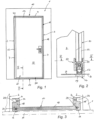
- the in Fig. 1 The door system 10 shown is preferably installed in a door opening of a wall 1, for example a lightweight wall.
- the door frame 11 with the frame profiles 12 (hinge side), 13 (top) and 14 (handle side) forms an aesthetically pleasing, narrow, three-sided frame in which a door element 20 with a door leaf 22 made of glass is rotatably mounted.
- the frame profiles 12, 13, 14 of the door frame 11 (or their base profiles 16) have groove-shaped receptacles 15 directed towards the reveal surfaces 2 of the door opening for the guide legs 6 of an adapter profile 3 which can be fastened to the reveal surfaces 2 of the door opening and with which the door frame 11 can be fixed in the door opening in such a way that the door frame 11 has a circumferential shadow gap 7 to the adjacent reveal surfaces 2 (see, for example, Fig. 4 and Fig. 5 ).
- an adjusting threshold 17 is provided which can be fastened to the floor of the door opening and which is equipped with end regions 18, 18' on both sides, which define the respective floor-side end of the stop-side 12 and the handle-side frame profile 14 and has a free threshold region 19 which connects the two end regions 18, 18' to one another.
- the adjusting threshold 17 is preferably made in one piece from sheet steel.
- the adjustment threshold 17 is aligned in a horizontal position using a measuring rod M or similar in the door opening of the wall 1, whereby either the contact surfaces a or b of the adjustment threshold 17 are brought into contact and the available width of the door opening is evenly divided (see Fig. 3 ).
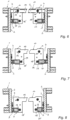
- the two end areas 18, 18' of the adjusting threshold 17 each have U-shaped recesses 23 directed towards the adjacent reveal surfaces 2 of the door opening, which serve to adjust the position of the adapter profiles 3 before they are attached to the reveal surfaces 2 (see, for example, Fig. 6 to Fig. 8 ).
- the adjustment effort when installing the door system 10 can be reduced considerably, since after the adjustment threshold has been installed (using screws 24 or assembly adhesive), the alignment and position of all other elements of the door system 10 is clearly specified. Furthermore, the exposed threshold area 19 or its surface forms a defined gap of constant width to the door element 20, which is also accessible for effective sound insulation.
- the free threshold area 19 of the adjustment threshold 17 can be designed as a contact surface embedded in the adjacent floor B for a sealing device 50 attached to the floor end of the door element 20 and lowerable in the closed position.
- the sealing device 50 whose housing 51 on the one hand accommodates the lower end of the glass door leaf 22 and on the other hand contains the lowerable sealing element 52, can preferably be arranged directly under the glass door leaf 22.
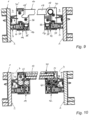
- the frame profiles 12 and 14 each have a base profile 16, which can be screwed to the adapter profile 3 attached to the reveal surface 2. Stops are attached to the base profiles 16. or on the handle side, different cover profiles 41, 42 are fastened, for example screwed on by means of cylinder head screws, wherein the cover profile 41 of the stop-side frame profile 12 and the rotatable sash profile 21 have mutually facing surfaces in the form of cylinder jacket sections, such that when the door element 20 is opened, a constant movement gap can be achieved between the mutually facing surfaces.
- a particularly aesthetic overall appearance of the door system 10 is achieved by the fact that the rotatable leaf profile 21 is integrated in the frame profile 12 on the stop side, whereby the width and depth of the two frame profiles 12 and 14 have the same values and are framed by a uniform shadow gap 7 to the reveal surfaces 2.
- two elastic sealing elements 25, 25' are arranged in the movement gap between the sash profile 21 and the cover profile 41, against which the sash profile 21 slides with its cylinder jacket section. This measure also makes it possible to achieve sufficient protection against pinching in the stop-side area of the door element 20.
- the base profile 16 of the handle-side frame profile 14 has a cover profile 42 in which a stop rebate for the door leaf 22 is formed, wherein a stop seal and a seal acting on the front side of the door leaf 22 are provided here, which ensure sound insulation on the handle side.
- FIG. 6 to Fig. 8 different installation positions of the adjustment threshold 19 in the door opening of the wall 1 are shown in a plan view.
- the Fig. 6 and Fig. 7 show an adjustment in which the contact surfaces a of the adjustment threshold 17 come into contact with a measuring rod not shown here.
- the contact surfaces b are used for adjustment.
- the adapter profiles 3 can - without further adjustment measures - be inserted with their lower ends into the U-shaped recesses 23 of the end regions 18, 18' of the adjustment threshold 17 and aligned vertically, as well as screwed to the reveal surfaces 2.
- shadow gaps 7 of different widths can be created - in the case of slightly different shell dimensions or dimensional tolerances of the door opening (see Fig. 6 to Fig. 8 ), which can be easily compensated with the adapter profiles 3.
- the separating joint T in the screed concrete between the inside and outside of the room in the area below the adjustment threshold 17 can be fixed using a suitable assembly adhesive.
- Fig. 9 shows starting from Fig. 7 a further assembly step in which the base profiles 16 of the stop-side 12 and the handle-side frame profile 14 are attached at the bottom end to screwing plates 30, 30', which are screwed to the corresponding end area 18, 18' of the adjustment threshold 17.
- the screwing plates 30, 30' are attached to the base profiles 16 by means of screws 35, which engage in screw channels of the base profiles 16.
- a block 37 for example made of wood, can be inserted between the guide legs 6 to better hold the screws 36 (see Fig. 9 ).
- a special contribution to sound insulation is achieved by arranging the base of a Y-shaped sealing element 31 in a groove of the adapter profile 3, the free legs 32 of which are in sealing contact with the cover profile 41 on the one hand and the leaf profile 21 of the door element 20 on the other hand, and bridge the shadow gap 7 formed between the stop-side frame profile 12 and the adjacent reveal surface 2 in a sound-insulating manner (see Fig. 10 ).
- Fig. 11 shows an exploded view of a door element 20 of the door system 10 shown at a reduced height, wherein the door element 20 has on the stop side the rotatable wing profile 21 which runs over the entire height of the door element 20 and is designed to clamp a door leaf 22 made of glass on the edge.
- the door element 20 is sound-insulated at the free threshold area 19 of the adjustment threshold 17 (not shown here) using the lowerable sealing device 50 arranged on the lower edge of the door leaf 22.
- the rotating sash profile 21 is closed by a lower, bottom-side pivot bearing element 26 (shown enlarged) and an upper pivot bearing element 27, whereby the lower pivot bearing element 26 interacts with a bearing receptacle 34 of the screwing plate 30 (see Fig. 12 ).
- the lower pivot bearing element 26 has a recess 33, whereby the sealing element 52, which is lowered from the housing 51 of the sealing device 50 can be brought closer to the axis of rotation of the door element 20 in order to effectively seal a gap in this area.
- the upper pivot bearing element 27 is received by an upper bearing holder 40, which is formed as part of the frame 11 forming the door frame (see Fig. 1 ).
- the rotatable wing profile 21 of the door element 20 has sealing elements 28, 29 at both ends, which sound-insulatingly seal the gap to the upper bearing holder 40 on the one hand and the gap to the screwing plate 30 fastened to the adjustment threshold 17 on the other hand.
- the sealing element 28 is in Fig. 11 shown enlarged and is arranged in a groove-shaped receptacle of the upper bearing receptacle 40.
- the sealing element 29 can be T-shaped and is arranged in a groove or a groove system of the screw plate 30 (see Fig. 12 ).
Landscapes
- Engineering & Computer Science (AREA)
- Civil Engineering (AREA)
- Structural Engineering (AREA)
- Mechanical Engineering (AREA)
- Specific Sealing Or Ventilating Devices For Doors And Windows (AREA)
Description
- Die Erfindung betrifft eine Türanlage für den Einbau in eine Türöffnung einer Wand, beispielsweise einer Beton-, Ziegel-, Holz- oder Leichtbauwand, mit einer einen Türrahmen bildenden Türzarge, in welcher ein Türelement drehbar gelagert ist, wobei die Türzarge ein anschlagseitiges, ein oberes und ein griffseitiges Zargenprofil aufweist, die jeweils mittels Adapterprofilen der Türanlage an den Laibungsflächen der Türöffnung befestigbar sind, wobei die Türzarge eine am Boden der Türöffnung befestigbare Justierschwelle aufweist, mit zwei Endbereichen, die das jeweilige bodenseitige Ende des anschlagseitigen und des griffseitigen Zargenprofils festlegen und mit einem freien Schwellenbereich in der Türöffnung, der die beiden Endbereiche miteinander verbindet.
- Aus der
AT 521 793 B1 - Das Türelement weist an der Anschlagseite ein über die gesamte Höhe des Türelements verlaufendes, drehbares Flügelprofil zur randseitigen, klemmenden Aufnahme eines Türblatts, beispielsweise aus Glas, auf, wobei das drehbare Flügelprofil mit seitlichem Abstand einer durch die Mitte der nutförmigen Aufnahmen der Zargenprofile definierten Ebene ε1 vorgelagert ist.
- Die seitlichen Zargenprofile werden mit Hilfe innen liegender Eckwinkel mit dem oberen Zargenprofil verbunden und mit bodenseitigen Basisplatten verschraubt, die ihrerseits mittels Schrauben am Boden befestigt sind.
- Nachteilig ist ein beträchtlicher Justieraufwand bei der Montage der Türzarge und deren exakte Ausrichtung in der Türöffnung der Wand.
- Im Zusammenhang mit einer ausreichenden Schalldämmung von Türanlagen, insbesondere im Türspalt zum Boden, werden beispielsweise absenkbare Dichtvorrichtungen verwendet, die am bodenseitigen Rand des Türelements befestigt oder in einer Nut des Türelements aufgenommen sind.
- Eine derartige absenkbare Bodendichtung wird in der
DE 20 2007 016 379 U1 beschrieben. In einem Gehäuse der Dichtvorrichtung ist ein parallel zum Boden absenkbares Dichtelement angeordnet, das in seiner Ruhestellung (bei geöffneter Tür) durch Federkraft in einer oberen Stellung gehalten wird. Beim Schließen der Tür kommt ein Auslöseelement mit dem Türfalz in Kontakt, wird nach Innen verschoben und betätigt über Umlenkkeile das Dichtelement in Richtung Boden, bis der Türspalt verschlossen wird. - Aus der
US 2 893 070 A ist eine Türzarge mit seitlichen Zargenprofilen, einem oberen Zargenprofil und einer Schwelle bekannt. Die Schwelle weist zwei Endbereiche auf, an welchen die seitlichen Zargenprofile festgelegt sind. Außerdem weist die Türzarge ein Adapterprofil auf, mit welchem das Zargenprofil an der Laibungsfläche befestigt werden kann. - Türelemente mit drei Zargenprofilen und einer Türschwelle sind auch aus den Dokumenten
CN 105 971 449 A undDE 10 2018 112434 A1 vorbekannt. - Schließlich offenbart die
US 3 769 773 A eine Türzarge mit seitlichen Zargenprofilen sowie einer an den seitlichen Zargenprofilen befestigbaren Schwelle. - Aufgabe der Erfindung ist es, ausgehend vom dargelegten Stand der Technik eine Türanlage für den Einbau in eine Türöffnung einer Wand vorzuschlagen, bei welcher der Montage- und Justieraufwand wesentlich verringert werden kann.
- Eine weitere Aufgabe der Erfindung besteht darin, den Schallschutz der gesamten Türanlage, inklusive deren Anbindung an die Türöffnung in der Wand, beispielsweise einer Leichtbauwand, zu verbessern.
- Diese Aufgabe wird erfindungsgemäß dadurch gelöst, dass die beiden Endbereiche der Justierschwelle jeweils zu den Laibungsflächen der Türöffnung gerichtete U-förmige Ausnehmungen aufweisen, die zur Lagejustierung der Adapterprofile vor deren Befestigung an den Laibungsflächen dienen.
- Der Justieraufwand bei der Montage der Türanlage reduziert sich bei der Erfindung im Wesentlichen auf die exakte Ausrichtung und den waagrechten Einbau der erfindungsgemäßen Justierschwelle in die Türöffnung, beispielsweise einer Leichtbauwand aus Gipskartonplatten.
- Die durch die Justierschwelle und deren freien Schwellenbereich definierte Ausbildung eines gleichmäßig verlaufenden Türspalts ist Voraussetzung für eine wesentliche Verbesserung des Schallschutzes der Gesamtanlage. Dabei ist der freie Schwellenbereich der Justierschwelle erfindungsgemäß als Anlagefläche für eine am bodenseitigen Ende des Türelements befestigte, in Schließstellung vorzugsweise absenkbare, Dichtvorrichtung ausgebildet.
- Durch weitere Schallschutzmaßnahmen, insbesondere der Verwendung von Schallschutzglas für das Türelement und einer im Querschnitt Y-förmigen Dichtung, die eine zwischen den anschlagseitigen und griffseitigen Zargenprofilen und den angrenzenden Laibungsflächen ausgebildete Schattenfuge schalldämmend überbrücken, können Dämmwerte von über 40 dB für die Gesamtanlage erzielt werden.
- Die Erfindung wird im Folgenden anhand von bevorzugten Ausführungsvarianten näher dargestellt. Es zeigen:
- Fig. 1
- die erfindungsgemäße Türanlage in einer Türöffnung einer Leichtbauwand in einer Gesamtansicht, betrachtet von der Öffnungsfläche des Drehtürelements;
- Fig. 2
- eine vergrößerte Schnittdarstellung gemäß Linie II - II in
Fig. 1 ; - Fig. 3
- eine Draufsicht auf die Justierschwelle am Boden der Türöffnung in der Leichtbauwand gemäß
Fig. 1 in vergrößerter Darstellung; - Fig. 4
- und
Fig. 5 Horizontalschnitte von Türanlagen im Bereich des bodenseitigen Endes der Drehtürelemente (siehe Linie IV - IV inFig. 2 ) bei unterschiedlicher Breite der Türöffnung in der Leichtbauwand; - Fig. 6
- bis
Fig. 8 unterschiedliche Einbaulagen der Justierschwelle der Türanlage in einer Draufsicht gemäßFig. 3 ; - Fig. 9
- und
Fig. 10 an einen ersten Montageschritt gemäßFig. 7 anschließende Montageschritte zwei (Fig. 9 ) und drei (Fig. 10 ); - Fig. 11
- Details des Drehtürelements der Türanlage gemäß
Fig. 1 in einer Explosionsdarstellung; sowie - Fig. 12
- eine Draufsicht auf die Anschraubplatte beim anschlagseitigen Zargenprofil der Türanlage.
- Die in
Fig. 1 dargestellte Türanlage 10 wird bevorzugt in eine Türöffnung einer Wand 1, beispielsweise einer Leichtbauwand, eingebaut. Die Türzarge 11 mit den Zargenprofilen 12 (anschlag- bzw. bandseitig), 13 (oben) und 14 (griffseitig) bildet einen ästhetisch ansprechenden, in der Ansicht schmal bauenden, dreiseitigen Rahmen, in welchem ein Türelement 20 mit einem Türblatt 22 aus Glas drehbar gelagert ist. Die Zargenprofile 12, 13, 14 der Türzarge 11 (bzw. deren Basisprofile 16) weisen zu den Laibungsflächen 2 der Türöffnung gerichtete, nutförmige Aufnahmen 15 für die Führungsschenkel 6 eines an den Laibungsflächen 2 der Türöffnung befestigbaren Adapterprofils 3 auf, mit welchem die Türzarge 11 in der Türöffnung festlegbar ist, derart, dass die Türzarge 11 eine umlaufende Schattenfuge 7 zu den angrenzenden Laibungsflächen 2 aufweist (siehe beispielsweiseFig. 4 und Fig. 5 ). - Wie in
Fig. 3 im Detail dargestellt, ist eine am Boden der Türöffnung befestigbare Justierschwelle 17 vorgesehen, die beidseitig mit Endbereichen 18, 18' ausgestattet ist, die das jeweilige bodenseitige Ende des anschlagseitigen 12 und des griffseitigen Zargenprofils 14 festlegen und einen freien Schwellenbereich 19 aufweist, der die beiden Endbereiche 18, 18' miteinander verbindet. Die Justierschwelle 17 wird bevorzugt einstückig aus Stahlblech hergestellt. - Die Justierschwelle 17 wird in waagrechter Lage mittels einer Messlatte M oder dgl. in der Türöffnung der Wand 1 ausgerichtet, wobei entweder die Anlageflächen a oder b der Justierschwelle 17 zur Anlage gebracht werden und die zur Verfügung stehende Breite der Türöffnung gleichmäßig aufgeteilt wird (siehe
Fig. 3 ). - Die beiden Endbereiche 18, 18' der Justierschwelle 17 weisen jeweils zu den benachbarten Laibungsflächen 2 der Türöffnung gerichtete, U-förmige Ausnehmungen 23 auf, die zur Lagejustierung der Adapterprofile 3 vor deren Befestigung an den Laibungsflächen 2 dienen (siehe beispielsweise
Fig. 6 bis Fig. 8 ). - Mit Hilfe der Justierschwelle 17 kann der Justieraufwand beim Einbau der Türanlage 10 beträchtlich verringert werden, da nach der Montage der Justierschwelle (mittels Schrauben 24 oder Montagekleber) die Ausrichtung und Lage aller weiteren Elemente der Türanlage 10 eindeutig vorgegeben ist. Weiters wird durch den frei liegenden Schwellenbereich 19 bzw. dessen Oberfläche ein definierter Spalt konstanter Breite zum Türelement 20 gebildet, der auch einer wirkungsvollen Schalldämmung zugängig ist.
- Wie in der Detaildarstellung gemäß
Fig. 2 gezeigt, kann der freie Schwellenbereich 19 der Justierschwelle 17 als in den angrenzenden Boden B eingelassene Anlagefläche für eine am bodenseitigen Ende des Türelements 20 befestigte, in Schließstellung absenkbare, Dichtvorrichtung 50 ausgebildet sein. Dabei kann die Dichtvorrichtung 50, deren Gehäuse 51 einerseits das untere Ende des Türblatts 22 aus Glas aufnimmt und andererseits das absenkbare Dichtelement 52 beinhaltet, bevorzugt direkt unter dem Türblatt 22 aus Glas angeordnet sein. - Wie beispielsweise in den
Fig. 4 und Fig. 5 dargestellt, weisen die Zargenprofile 12 und 14 jeweils ein Basisprofil 16 auf, das mit dem an der Laibungsfläche 2 befestigten Adapterprofil 3 verschraubbar ist. An den Basisprofilen 16 sind anschlag- bzw. griffseitig unterschiedliche Deckprofile 41, 42 befestigt, beispielsweise mittels Zylinderkopfschrauben angeschraubt, wobei das Deckprofil 41 des anschlagseitigen Zargenprofils 12 und das drehbare Flügelprofil 21 einander zugekehrte Oberflächen in Form von Zylindermantelabschnitten aufweisen, derart, dass beim Öffnen des Türelements 20 ein gleichbleibender Bewegungsspalt zwischen den einander zugekehrten Oberflächen erzielbar ist. - Ein besonders ästhetisches Gesamtbild der Türanlage 10 ergibt sich dadurch, dass das drehbare Flügelprofil 21 im anschlagseitigen Zargenprofil 12 integriert ist, wodurch die Breite und die Tiefe der beiden Zargenprofile 12 und 14 gleiche Werte aufweisen und von einer gleichmäßigen Schattenfuge 7 zu den Laibungsflächen 2 eingerahmt sind.
- Zur Verbesserung der Schalldämmung sind im Bewegungsspalt zwischen dem Flügelprofil 21 und dem Deckprofil 41 zwei elastische Dichtelement 25, 25' angeordnet ist, an welchen das Flügelprofil 21 mit dessen Zylindermantelabschnitt gleitend anliegt. Durch diese Maßnahme kann weiters ein ausreichender Einklemmschutz im anschlagseitigen Bereich des Türelements 20 erzielt werden.
- Das Basisprofil 16 des griffseitigen Zargenprofils 14 weist ein Deckprofil 42 auf, in welchem ein Anschlagfalz für das Türblatt 22 ausgebildet ist, wobei hier eine Anschlagdichtung und eine auf die Stirnseite des Türblatts 22 wirkende Dichtung vorgesehen sind, die den Schallschutz griffseitig gewährleisten.
- In den
Fig. 6 bis Fig. 8 sind unterschiedliche Einbaulagen der Justierschwelle 19 in der Türöffnung der Wand 1 in einer Draufsicht dargestellt. DieFig. 6 und Fig. 7 zeigen eine Justierung bei der die Anlageflächen a der Justierschwelle 17 zur Anlage an eine hier nicht dargestellte Messlatte kommen. Bei der Variante gemäßFig. 8 werden die Anlageflächen b für die Justierung verwendet. - In jedem Fall können die Adapterprofile 3 - ohne weitere Justiermaßnahmen - mit deren unteren Enden in die U-förmigen Ausnehmungen 23 der Endbereiche 18, 18' der Justierschwelle 17 eingesetzt und senkrecht ausgerichtet werden, sowie an den Laibungsflächen 2 angeschraubt werden.
- Durch die Zentrierung der Justierschwelle 17 in der Mitte der Türöffnung können - bei leicht unterschiedlichen Rohbaumaßen bzw. Maßtoleranzen der Türöffnung - unterschiedlich breite Schattenfugen 7 entstehen (siehe
Fig. 6 bis Fig. 8 ), die jedoch auf einfache Weise mit den Adapterprofilen 3 ausgeglichen werden können. - Zur Unterbindung der Übertragung von Körperschall, kann die Trennfuge T im Estrichbeton zwischen der Rauminnenseite und der Raumaußenseite im Bereich unterhalb der Justierschwelle 17 angeordnet sein (siehe
Fig. 6 ). Falls in diesem Bereich eine Befestigung durch Schauben 24 nicht möglich ist, kann die Justierschwelle 17 mittels eines geeigneten Montageklebers fixiert werden. -
Fig. 9 zeigt ausgehend vonFig. 7 einen weiteren Montageschritt, bei welchem die Basisprofile 16 des anschlagseitigen 12 und des griffseitigen Zargenprofils 14 am bodenseitigen Ende an Anschraubplatten 30, 30' befestigt sind, die mit dem entsprechenden Endbereich 18, 18' der Justierschwelle 17 verschraubt werden. Die Anschraubplatten 30, 30' sind mittels Schrauben 35, die in Schraubkanäle der Basisprofile 16 eingreifen an den Basisprofilen 16 befestigt. - Bei der Verschraubung des Basisprofils 16 mit den Führungsschenkeln 6 des Adapterprofils 3 kann zum besseren Halt der Schrauben 36 ein Klotz 37, beispielsweise aus Holz, zwischen den Führungsschenkel 6 eingefügt sein (siehe
Fig. 9 ). - Ein besonderer Beitrag zur Schalldämmung wird dadurch erreicht, dass in einer Nut des Adapterprofils 3 die Basis eines Y-förmigen Dichtelements 31 angeordnet ist, dessen freien Schenkel 32 einerseits am Deckprofil 41 und andererseits am Flügelprofil 21 des Türelements 20 dichtend anliegen und die zwischen dem anschlagseitigen Zargenprofil 12 und der angrenzenden Laibungsfläche 2 ausgebildete Schattenfuge 7 schalldämmend überbrücken (siehe
Fig. 10 ). Gleiches gilt natürlich für das griffseitige Zargenprofil 14, wo die freien Schenkel 32 des Y-förmigen Dichtelements 31 am Deckprofil 42 des griffseitigen Zargenprofils 14 dichtend anliegen und eine zwischen dem griffseitigen Zargenprofil 14 und der angrenzenden Laibungsfläche 2 ausgebildete Schattenfuge 7 schalldämmend überbrücken. -
Fig. 11 zeigt in Explosionsdarstellung ein in der Höhe verkleinert dargestelltes Türelement 20 der Türanlage 10, wobei das Türelement 20 an der Anschlagseite das über die gesamte Höhe des Türelements 20 verlaufende, drehbare Flügelprofil 21 aufweist, das zur randseitigen, klemmenden Aufnahme eines Türblatts 22 aus Glas ausgebildet ist. In Schließstellung wird das Türelements 20 mit Hilfe der am unteren Rand des Türblatts 22 angeordneten, absenkbaren Dichtvorrichtung 50 schalldämmend am freien Schwellenbereichs 19 der Justierschwelle 17 (hier nicht dargestellt) abgedichtet. - Das drehbare Flügelprofil 21 wird durch ein unteres, bodenseitiges Drehlagerelement 26 (vergrößert dargestellt) und ein oberes Drehlagerelement 27 abgeschlossen, wobei das untere Drehlagerelement 26 mit einer Lageraufnahme 34 der Anschraubplatte 30 zusammenwirkt (siehe
Fig. 12 ). - Das untere Drehlagerelement 26 weist eine Ausnehmung 33 auf, wodurch das Dichtelement 52, das aus dem Gehäuse 51 der Dichtvorrichtung 50 abgesenkt werden kann, näher an die Drehachse des Türelements 20 herangeführt werden kann, um einen Spalt in diesem Bereich wirksam abzudichten.
- Das obere Drehlagerelement 27 wird von einer oberen Lageraufnahme 40 aufgenommen, die als Teil der den Türrahmen bildenden Zarge 11 ausgebildet ist (siehe
Fig. 1 ). - Das drehbare Flügelprofil 21 des Türelements 20 weist an beiden Enden Dichtelemente 28, 29 auf, die einerseits den Spalt zur oberen Lageraufnahme 40 und andererseits den Spalt zu der an der Justierschwelle 17 befestigten Anschraubplatte 30 schalldämmend abdichten.
- Das Dichtelement 28 ist in
Fig. 11 vergrößert dargestellt und ist in einer nutförmigen Aufnahme der oberen Lageraufnahme 40 angeordnet. Das Dichtelement 29 kann T-förmig ausgebildet sein und ist in einer Nut oder einem Nutsystem der Anschraubplatte 30 angeordnet (sieheFig. 12 ).
Claims (10)
- Türanlage (10) für den Einbau in eine Türöffnung einer Wand (1), mit einer einen Türrahmen bildenden Türzarge (11), in welcher ein Türelement (20) drehbar gelagert ist, wobei die Türzarge (11) ein anschlagseitiges (12), ein oberes (13) und ein griffseitiges Zargenprofil (14) aufweist, die jeweils mittels Adapterprofilen (3) der Türanlage (10) an den Laibungsflächen (2) der Türöffnung befestigbar sind, wobei die Türzarge (11) eine am Boden der Türöffnung befestigbare Justierschwelle (17) aufweist, mit zwei Endbereichen (18, 18'), die das jeweilige bodenseitige Ende des anschlagseitigen (12) und des griffseitigen Zargenprofils (14) festlegen und mit einem freien Schwellenbereich (19) in der Türöffnung, der die beiden Endbereiche (18, 18') miteinander verbindet, dadurch gekennzeichnet, dass die beiden Endbereiche (18, 18') der Justierschwelle (17) jeweils zu den Laibungsflächen (2) der Türöffnung gerichtete U-förmige Ausnehmungen (23) aufweisen, die zur Lagejustierung der Adapterprofile (3) vor deren Befestigung an den Laibungsflächen (2) dienen.
- Türanlage (10) nach Anspruch 1, dadurch gekennzeichnet, dass das anschlagseitige und das griffseitige Zargenprofil (12, 14) jeweils ein Basisprofil (16) aufweisen, das am bodenseitigen Ende eine Anschraubplatte (30, 30') aufweist, die mit dem entsprechenden Endbereich (18, 18') der Justierschwelle (17) verschraubbar ist.
- Türanlage (10) nach Anspruch 1 oder 2, dadurch gekennzeichnet, dass der freie Schwellenbereich (19) der Justierschwelle (17) als Anlagefläche für eine am bodenseitigen Ende des Türelements (20) befestigte, in Schließstellung vorzugsweise absenkbare, Dichtvorrichtung (50) ausgebildet ist.
- Türanlage (10) nach Anspruch 3, dadurch gekennzeichnet, dass das Türelement (20) an der Anschlagseite ein über die gesamte Höhe des Türelements (20) verlaufendes, drehbares Flügelprofil (21) zur randseitigen, klemmenden Aufnahme eines Türblatts (22) aus Glas, aufweist, welches in Schließstellung des Türelements (20) - unter Zwischenlage der Dichtvorrichtung (50) - oberhalb des freien Schwellenbereichs (19) der Justierschwelle (17) angeordnet ist.
- Türanlage (10) nach Anspruch 4, dadurch gekennzeichnet, dass das drehbare Flügelprofil (21) im anschlagseitigen Zargenprofil (12) integriert ist.
- Türanlage (10) nach Anspruch 4 oder 5, dadurch gekennzeichnet, dass das Basisprofil (16) des anschlagseitigen Zargenprofils (12) ein Deckprofil (41) aufweist, das einen Bewegungsspalt zum Flügelprofil (21) ausbildet, wobei im Bewegungsspalt elastische Dichtelemente (25, 25') angeordnet sind, an welchen das Flügelprofil (21) gleitend anliegt.
- Türanlage (10) nach Anspruch 6, dadurch gekennzeichnet, dass in einer Nut des Adapterprofils (3) die Basis eines Y-förmigen Dichtelements (31) angeordnet ist, dessen freien Schenkel (32) einerseits am Deckprofil (41) und andererseits am Flügelprofil (21) des Türelements (20) dichtend anliegen und eine zwischen dem anschlagseitigen Zargenprofil (12) und der angrenzenden Laibungsfläche (2) ausgebildete Schattenfuge (7) schalldämmend überbrücken.
- Türanlage (10) nach einem der Ansprüche 2 bis 7, dadurch gekennzeichnet, dass das Basisprofil (16) des griffseitigen Zargenprofils (14) ein Deckprofil (42) aufweist, in welchem ein Anschlagfalz für das Türblatt (22) des Türelements (20) ausgebildet ist.
- Türanlage (10) nach Anspruch 8, dadurch gekennzeichnet, dass in einer Nut des Adapterprofils (3) die Basis eines Y-förmigen Dichtelements (31) angeordnet ist, dessen freien Schenkel (32) am Deckprofil (42) des griffseitigen Zargenprofils (14) dichtend anliegen und eine zwischen dem griffseitigen Zargenprofil (14) und der angrenzenden Laibungsfläche (2) ausgebildete Schattenfuge (7) schalldämmend überbrücken.
- Türanlage (10) nach einem der Ansprüche 4 bis 9, dadurch gekennzeichnet, dass das drehbare Flügelprofil (21) des Türelements (20) an beiden Enden Dichtelemente (28, 29) aufweist, die einerseits den Spalt zu einer oberen Lageraufnahme (40) und andererseits den Spalt zu einer an der Justierschwelle (17) befestigbaren Anschraubplatte (30) schalldämmend abdichten.
Applications Claiming Priority (2)
| Application Number | Priority Date | Filing Date | Title |
|---|---|---|---|
| ATA50278/2021A AT524201B1 (de) | 2021-04-14 | 2021-04-14 | Türanlage für den einbau in eine türöffnung einer wand |
| DE102021109396.1A DE102021109396A1 (de) | 2021-04-14 | 2021-04-14 | Türanlage für den Einbau in eine Türöffnung einer Wand |
Publications (3)
| Publication Number | Publication Date |
|---|---|
| EP4074933A1 EP4074933A1 (de) | 2022-10-19 |
| EP4074933C0 EP4074933C0 (de) | 2025-02-12 |
| EP4074933B1 true EP4074933B1 (de) | 2025-02-12 |
Family
ID=80930525
Family Applications (1)
| Application Number | Title | Priority Date | Filing Date |
|---|---|---|---|
| EP22163445.4A Active EP4074933B1 (de) | 2021-04-14 | 2022-03-22 | Türanlage für den einbau in eine türöffnung einer wand |
Country Status (1)
| Country | Link |
|---|---|
| EP (1) | EP4074933B1 (de) |
Family Cites Families (6)
| Publication number | Priority date | Publication date | Assignee | Title |
|---|---|---|---|---|
| US2893070A (en) * | 1957-11-15 | 1959-07-07 | Raymond V Gauthier | Adjustable weather-stripped door jamb |
| US3769773A (en) * | 1972-06-05 | 1973-11-06 | M Mochizuki | Collapsible door-fitting frame |
| DE202007016379U1 (de) | 2007-11-21 | 2009-04-09 | F. Athmer Ohg | Absenkbare Bodendichtung mit zumindest teilweise weichem Auslöseelement |
| CN105971449A (zh) * | 2016-07-05 | 2016-09-28 | 浙江瑞明节能科技股份有限公司 | 一种带门槛的门框装置 |
| DE102018112434A1 (de) * | 2018-05-24 | 2019-11-28 | SCHÜCO International KG | Fenster |
| AT521793B1 (de) | 2019-06-26 | 2020-07-15 | Elmer Hubert | Türanlage für den einbau in eine türöffnung |
-
2022
- 2022-03-22 EP EP22163445.4A patent/EP4074933B1/de active Active
Also Published As
| Publication number | Publication date |
|---|---|
| EP4074933A1 (de) | 2022-10-19 |
| EP4074933C0 (de) | 2025-02-12 |
Similar Documents
| Publication | Publication Date | Title |
|---|---|---|
| EP3306020B1 (de) | Vorrichtung für das verschliessen einer gebäudeöffnung | |
| DE29507176U1 (de) | Rahmenlose Glastür | |
| WO2010079125A1 (de) | Profilsystem für eine schiebetür | |
| DE2059829A1 (de) | Struktursystem fuer den Zusammenbau von vorgefertigten Konstruktionen | |
| EP2618706B1 (de) | Duschwand mit einer schiebetür | |
| DE102005022042B3 (de) | Mehrdimensional verstellbares Türband an einem Türflügel | |
| EP4074933B1 (de) | Türanlage für den einbau in eine türöffnung einer wand | |
| AT521793B1 (de) | Türanlage für den einbau in eine türöffnung | |
| AT524201B1 (de) | Türanlage für den einbau in eine türöffnung einer wand | |
| EP1124473B1 (de) | Dusch- oder badewannenabtrennung | |
| EP1666691B1 (de) | Türblatt mit Vorrichtung zur Längeneinstellung | |
| DE102021109396A1 (de) | Türanlage für den Einbau in eine Türöffnung einer Wand | |
| EP0663039B1 (de) | Nebentür | |
| DE102004055803A1 (de) | Rahmenloses Isolierglaselement sowie Beschlag- oder Befestigungssystem für das Isolierglaselement | |
| DE102008064836B3 (de) | Pfostenleiste zur Anbringung an einem vertikalen Laibungsabschnitt einer Türöffnung sowie Montageeinrichtung zur Befestigung in der Laibung einer Türöffnung | |
| DE3700201C2 (de) | ||
| DE2518765A1 (de) | Tuerfutter mit zwei beidseits angeordneten falzverkleidungen | |
| DE10054175A1 (de) | Einbruchhemmende Fensterkonstruktion | |
| EP3831257B1 (de) | Anordnung mit einem glassicherungsprofil | |
| EP0115554A1 (de) | Einrichtung zur Verkleidung eines Türstockes | |
| DE10231841A1 (de) | Schiebetür | |
| EP2592208B1 (de) | Tor | |
| AT521978B1 (de) | Türanlage für ein trennwandsystem | |
| EP4086417A1 (de) | Schiene für eine schiebetür und montageverfahren | |
| AT18586U1 (de) | Fenster |
Legal Events
| Date | Code | Title | Description |
|---|---|---|---|
| PUAI | Public reference made under article 153(3) epc to a published international application that has entered the european phase |
Free format text: ORIGINAL CODE: 0009012 |
|
| STAA | Information on the status of an ep patent application or granted ep patent |
Free format text: STATUS: THE APPLICATION HAS BEEN PUBLISHED |
|
| AK | Designated contracting states |
Kind code of ref document: A1 Designated state(s): AL AT BE BG CH CY CZ DE DK EE ES FI FR GB GR HR HU IE IS IT LI LT LU LV MC MK MT NL NO PL PT RO RS SE SI SK SM TR |
|
| STAA | Information on the status of an ep patent application or granted ep patent |
Free format text: STATUS: REQUEST FOR EXAMINATION WAS MADE |
|
| 17P | Request for examination filed |
Effective date: 20230418 |
|
| RBV | Designated contracting states (corrected) |
Designated state(s): AL AT BE BG CH CY CZ DE DK EE ES FI FR GB GR HR HU IE IS IT LI LT LU LV MC MK MT NL NO PL PT RO RS SE SI SK SM TR |
|
| GRAP | Despatch of communication of intention to grant a patent |
Free format text: ORIGINAL CODE: EPIDOSNIGR1 |
|
| STAA | Information on the status of an ep patent application or granted ep patent |
Free format text: STATUS: GRANT OF PATENT IS INTENDED |
|
| RIC1 | Information provided on ipc code assigned before grant |
Ipc: E06B 7/36 20060101ALI20240510BHEP Ipc: E06B 3/36 20060101ALI20240510BHEP Ipc: E06B 1/60 20060101ALI20240510BHEP Ipc: E06B 7/21 20060101ALI20240510BHEP Ipc: E06B 3/34 20060101ALI20240510BHEP Ipc: E06B 3/02 20060101ALI20240510BHEP Ipc: E06B 1/70 20060101ALI20240510BHEP Ipc: E06B 1/52 20060101AFI20240510BHEP |
|
| INTG | Intention to grant announced |
Effective date: 20240612 |
|
| GRAJ | Information related to disapproval of communication of intention to grant by the applicant or resumption of examination proceedings by the epo deleted |
Free format text: ORIGINAL CODE: EPIDOSDIGR1 |
|
| STAA | Information on the status of an ep patent application or granted ep patent |
Free format text: STATUS: REQUEST FOR EXAMINATION WAS MADE |
|
| GRAS | Grant fee paid |
Free format text: ORIGINAL CODE: EPIDOSNIGR3 |
|
| STAA | Information on the status of an ep patent application or granted ep patent |
Free format text: STATUS: GRANT OF PATENT IS INTENDED |
|
| GRAP | Despatch of communication of intention to grant a patent |
Free format text: ORIGINAL CODE: EPIDOSNIGR1 |
|
| INTC | Intention to grant announced (deleted) | ||
| INTG | Intention to grant announced |
Effective date: 20241022 |
|
| GRAA | (expected) grant |
Free format text: ORIGINAL CODE: 0009210 |
|
| STAA | Information on the status of an ep patent application or granted ep patent |
Free format text: STATUS: THE PATENT HAS BEEN GRANTED |
|
| AK | Designated contracting states |
Kind code of ref document: B1 Designated state(s): AL AT BE BG CH CY CZ DE DK EE ES FI FR GB GR HR HU IE IS IT LI LT LU LV MC MK MT NL NO PL PT RO RS SE SI SK SM TR |
|
| REG | Reference to a national code |
Ref country code: GB Ref legal event code: FG4D Free format text: NOT ENGLISH |
|
| REG | Reference to a national code |
Ref country code: CH Ref legal event code: EP |
|
| REG | Reference to a national code |
Ref country code: DE Ref legal event code: R096 Ref document number: 502022002840 Country of ref document: DE |
|
| REG | Reference to a national code |
Ref country code: IE Ref legal event code: FG4D Free format text: LANGUAGE OF EP DOCUMENT: GERMAN |
|
| U01 | Request for unitary effect filed |
Effective date: 20250310 |
|
| U07 | Unitary effect registered |
Designated state(s): AT BE BG DE DK EE FI FR IT LT LU LV MT NL PT RO SE SI Effective date: 20250317 |
|
| U20 | Renewal fee for the european patent with unitary effect paid |
Year of fee payment: 4 Effective date: 20250319 |
|
| PGFP | Annual fee paid to national office [announced via postgrant information from national office to epo] |
Ref country code: AT Payment date: 20250417 Year of fee payment: 4 |
|
| PG25 | Lapsed in a contracting state [announced via postgrant information from national office to epo] |
Ref country code: RS Free format text: LAPSE BECAUSE OF FAILURE TO SUBMIT A TRANSLATION OF THE DESCRIPTION OR TO PAY THE FEE WITHIN THE PRESCRIBED TIME-LIMIT Effective date: 20250512 |
|
| PG25 | Lapsed in a contracting state [announced via postgrant information from national office to epo] |
Ref country code: PL Free format text: LAPSE BECAUSE OF FAILURE TO SUBMIT A TRANSLATION OF THE DESCRIPTION OR TO PAY THE FEE WITHIN THE PRESCRIBED TIME-LIMIT Effective date: 20250212 |
|
| PG25 | Lapsed in a contracting state [announced via postgrant information from national office to epo] |
Ref country code: ES Free format text: LAPSE BECAUSE OF FAILURE TO SUBMIT A TRANSLATION OF THE DESCRIPTION OR TO PAY THE FEE WITHIN THE PRESCRIBED TIME-LIMIT Effective date: 20250212 |
|
| PG25 | Lapsed in a contracting state [announced via postgrant information from national office to epo] |
Ref country code: IS Free format text: LAPSE BECAUSE OF FAILURE TO SUBMIT A TRANSLATION OF THE DESCRIPTION OR TO PAY THE FEE WITHIN THE PRESCRIBED TIME-LIMIT Effective date: 20250612 Ref country code: NO Free format text: LAPSE BECAUSE OF FAILURE TO SUBMIT A TRANSLATION OF THE DESCRIPTION OR TO PAY THE FEE WITHIN THE PRESCRIBED TIME-LIMIT Effective date: 20250512 |
|
| PG25 | Lapsed in a contracting state [announced via postgrant information from national office to epo] |
Ref country code: HR Free format text: LAPSE BECAUSE OF FAILURE TO SUBMIT A TRANSLATION OF THE DESCRIPTION OR TO PAY THE FEE WITHIN THE PRESCRIBED TIME-LIMIT Effective date: 20250212 |
|
| PG25 | Lapsed in a contracting state [announced via postgrant information from national office to epo] |
Ref country code: GR Free format text: LAPSE BECAUSE OF FAILURE TO SUBMIT A TRANSLATION OF THE DESCRIPTION OR TO PAY THE FEE WITHIN THE PRESCRIBED TIME-LIMIT Effective date: 20250513 |
|
| PG25 | Lapsed in a contracting state [announced via postgrant information from national office to epo] |
Ref country code: SM Free format text: LAPSE BECAUSE OF FAILURE TO SUBMIT A TRANSLATION OF THE DESCRIPTION OR TO PAY THE FEE WITHIN THE PRESCRIBED TIME-LIMIT Effective date: 20250212 |
|
| PG25 | Lapsed in a contracting state [announced via postgrant information from national office to epo] |
Ref country code: CZ Free format text: LAPSE BECAUSE OF FAILURE TO SUBMIT A TRANSLATION OF THE DESCRIPTION OR TO PAY THE FEE WITHIN THE PRESCRIBED TIME-LIMIT Effective date: 20250212 |
|
| REG | Reference to a national code |
Ref country code: CH Ref legal event code: H13 Free format text: ST27 STATUS EVENT CODE: U-0-0-H10-H13 (AS PROVIDED BY THE NATIONAL OFFICE) Effective date: 20251024 |
|
| PG25 | Lapsed in a contracting state [announced via postgrant information from national office to epo] |
Ref country code: SK Free format text: LAPSE BECAUSE OF FAILURE TO SUBMIT A TRANSLATION OF THE DESCRIPTION OR TO PAY THE FEE WITHIN THE PRESCRIBED TIME-LIMIT Effective date: 20250212 |
|
| PLBE | No opposition filed within time limit |
Free format text: ORIGINAL CODE: 0009261 |
|
| STAA | Information on the status of an ep patent application or granted ep patent |
Free format text: STATUS: NO OPPOSITION FILED WITHIN TIME LIMIT |
|
| PG25 | Lapsed in a contracting state [announced via postgrant information from national office to epo] |
Ref country code: MC Free format text: LAPSE BECAUSE OF FAILURE TO SUBMIT A TRANSLATION OF THE DESCRIPTION OR TO PAY THE FEE WITHIN THE PRESCRIBED TIME-LIMIT Effective date: 20250212 |
|
| PG25 | Lapsed in a contracting state [announced via postgrant information from national office to epo] |
Ref country code: CH Free format text: LAPSE BECAUSE OF NON-PAYMENT OF DUE FEES Effective date: 20250331 |
|
| PG25 | Lapsed in a contracting state [announced via postgrant information from national office to epo] |
Ref country code: IE Free format text: LAPSE BECAUSE OF NON-PAYMENT OF DUE FEES Effective date: 20250322 |
|
| 26N | No opposition filed |
Effective date: 20251113 |