EP4074945B1 - System zur betätigung eines einlassventils einer brennkraftmaschine - Google Patents
System zur betätigung eines einlassventils einer brennkraftmaschine Download PDFInfo
- Publication number
- EP4074945B1 EP4074945B1 EP21168009.5A EP21168009A EP4074945B1 EP 4074945 B1 EP4074945 B1 EP 4074945B1 EP 21168009 A EP21168009 A EP 21168009A EP 4074945 B1 EP4074945 B1 EP 4074945B1
- Authority
- EP
- European Patent Office
- Prior art keywords
- cam
- valve
- intake
- intake valves
- cylinder
- Prior art date
- Legal status (The legal status is an assumption and is not a legal conclusion. Google has not performed a legal analysis and makes no representation as to the accuracy of the status listed.)
- Active
Links
Images

Classifications
-
- F—MECHANICAL ENGINEERING; LIGHTING; HEATING; WEAPONS; BLASTING
- F01—MACHINES OR ENGINES IN GENERAL; ENGINE PLANTS IN GENERAL; STEAM ENGINES
- F01L—CYCLICALLY OPERATING VALVES FOR MACHINES OR ENGINES
- F01L1/00—Valve-gear or valve arrangements, e.g. lift-valve gear
- F01L1/34—Valve-gear or valve arrangements, e.g. lift-valve gear characterised by the provision of means for changing the timing of the valves without changing the duration of opening and without affecting the magnitude of the valve lift
- F01L1/344—Valve-gear or valve arrangements, e.g. lift-valve gear characterised by the provision of means for changing the timing of the valves without changing the duration of opening and without affecting the magnitude of the valve lift changing the angular relationship between crankshaft and camshaft, e.g. using helicoidal gear
- F01L1/3442—Valve-gear or valve arrangements, e.g. lift-valve gear characterised by the provision of means for changing the timing of the valves without changing the duration of opening and without affecting the magnitude of the valve lift changing the angular relationship between crankshaft and camshaft, e.g. using helicoidal gear using hydraulic chambers with variable volume to transmit the rotating force
-
- F—MECHANICAL ENGINEERING; LIGHTING; HEATING; WEAPONS; BLASTING
- F01—MACHINES OR ENGINES IN GENERAL; ENGINE PLANTS IN GENERAL; STEAM ENGINES
- F01L—CYCLICALLY OPERATING VALVES FOR MACHINES OR ENGINES
- F01L13/00—Modifications of valve-gear to facilitate reversing, braking, starting, changing compression ratio, or other specific operations
- F01L13/0015—Modifications of valve-gear to facilitate reversing, braking, starting, changing compression ratio, or other specific operations for optimising engine performances by modifying valve lift according to various working parameters, e.g. rotational speed, load, torque
- F01L13/0036—Modifications of valve-gear to facilitate reversing, braking, starting, changing compression ratio, or other specific operations for optimising engine performances by modifying valve lift according to various working parameters, e.g. rotational speed, load, torque the valves being driven by two or more cams with different shape, size or timing or a single cam profiled in axial and radial direction
- F01L13/0047—Modifications of valve-gear to facilitate reversing, braking, starting, changing compression ratio, or other specific operations for optimising engine performances by modifying valve lift according to various working parameters, e.g. rotational speed, load, torque the valves being driven by two or more cams with different shape, size or timing or a single cam profiled in axial and radial direction the movement of the valves resulting from the sum of the simultaneous actions of at least two cams, the cams being independently variable in phase in respect of each other
-
- F—MECHANICAL ENGINEERING; LIGHTING; HEATING; WEAPONS; BLASTING
- F01—MACHINES OR ENGINES IN GENERAL; ENGINE PLANTS IN GENERAL; STEAM ENGINES
- F01L—CYCLICALLY OPERATING VALVES FOR MACHINES OR ENGINES
- F01L13/00—Modifications of valve-gear to facilitate reversing, braking, starting, changing compression ratio, or other specific operations
- F01L13/06—Modifications of valve-gear to facilitate reversing, braking, starting, changing compression ratio, or other specific operations for braking
-
- F—MECHANICAL ENGINEERING; LIGHTING; HEATING; WEAPONS; BLASTING
- F01—MACHINES OR ENGINES IN GENERAL; ENGINE PLANTS IN GENERAL; STEAM ENGINES
- F01L—CYCLICALLY OPERATING VALVES FOR MACHINES OR ENGINES
- F01L9/00—Valve-gear or valve arrangements actuated non-mechanically
- F01L9/10—Valve-gear or valve arrangements actuated non-mechanically by fluid means, e.g. hydraulic
- F01L9/11—Valve-gear or valve arrangements actuated non-mechanically by fluid means, e.g. hydraulic in which the action of a cam is being transmitted to a valve by a liquid column
- F01L9/12—Valve-gear or valve arrangements actuated non-mechanically by fluid means, e.g. hydraulic in which the action of a cam is being transmitted to a valve by a liquid column with a liquid chamber between a piston actuated by a cam and a piston acting on a valve stem
-
- F—MECHANICAL ENGINEERING; LIGHTING; HEATING; WEAPONS; BLASTING
- F01—MACHINES OR ENGINES IN GENERAL; ENGINE PLANTS IN GENERAL; STEAM ENGINES
- F01L—CYCLICALLY OPERATING VALVES FOR MACHINES OR ENGINES
- F01L13/00—Modifications of valve-gear to facilitate reversing, braking, starting, changing compression ratio, or other specific operations
- F01L13/0005—Deactivating valves
-
- F—MECHANICAL ENGINEERING; LIGHTING; HEATING; WEAPONS; BLASTING
- F01—MACHINES OR ENGINES IN GENERAL; ENGINE PLANTS IN GENERAL; STEAM ENGINES
- F01L—CYCLICALLY OPERATING VALVES FOR MACHINES OR ENGINES
- F01L1/00—Valve-gear or valve arrangements, e.g. lift-valve gear
- F01L1/02—Valve drive
- F01L1/04—Valve drive by means of cams, camshafts, cam discs, eccentrics or the like
- F01L1/047—Camshafts
- F01L1/053—Camshafts overhead type
- F01L2001/0537—Double overhead camshafts [DOHC]
-
- F—MECHANICAL ENGINEERING; LIGHTING; HEATING; WEAPONS; BLASTING
- F01—MACHINES OR ENGINES IN GENERAL; ENGINE PLANTS IN GENERAL; STEAM ENGINES
- F01L—CYCLICALLY OPERATING VALVES FOR MACHINES OR ENGINES
- F01L1/00—Valve-gear or valve arrangements, e.g. lift-valve gear
- F01L1/34—Valve-gear or valve arrangements, e.g. lift-valve gear characterised by the provision of means for changing the timing of the valves without changing the duration of opening and without affecting the magnitude of the valve lift
- F01L1/344—Valve-gear or valve arrangements, e.g. lift-valve gear characterised by the provision of means for changing the timing of the valves without changing the duration of opening and without affecting the magnitude of the valve lift changing the angular relationship between crankshaft and camshaft, e.g. using helicoidal gear
- F01L1/3442—Valve-gear or valve arrangements, e.g. lift-valve gear characterised by the provision of means for changing the timing of the valves without changing the duration of opening and without affecting the magnitude of the valve lift changing the angular relationship between crankshaft and camshaft, e.g. using helicoidal gear using hydraulic chambers with variable volume to transmit the rotating force
- F01L2001/34423—Details relating to the hydraulic feeding circuit
- F01L2001/34426—Oil control valves
-
- F—MECHANICAL ENGINEERING; LIGHTING; HEATING; WEAPONS; BLASTING
- F01—MACHINES OR ENGINES IN GENERAL; ENGINE PLANTS IN GENERAL; STEAM ENGINES
- F01L—CYCLICALLY OPERATING VALVES FOR MACHINES OR ENGINES
- F01L1/00—Valve-gear or valve arrangements, e.g. lift-valve gear
- F01L1/34—Valve-gear or valve arrangements, e.g. lift-valve gear characterised by the provision of means for changing the timing of the valves without changing the duration of opening and without affecting the magnitude of the valve lift
- F01L1/344—Valve-gear or valve arrangements, e.g. lift-valve gear characterised by the provision of means for changing the timing of the valves without changing the duration of opening and without affecting the magnitude of the valve lift changing the angular relationship between crankshaft and camshaft, e.g. using helicoidal gear
- F01L1/3442—Valve-gear or valve arrangements, e.g. lift-valve gear characterised by the provision of means for changing the timing of the valves without changing the duration of opening and without affecting the magnitude of the valve lift changing the angular relationship between crankshaft and camshaft, e.g. using helicoidal gear using hydraulic chambers with variable volume to transmit the rotating force
- F01L2001/34423—Details relating to the hydraulic feeding circuit
- F01L2001/34426—Oil control valves
- F01L2001/34433—Location oil control valves
-
- F—MECHANICAL ENGINEERING; LIGHTING; HEATING; WEAPONS; BLASTING
- F01—MACHINES OR ENGINES IN GENERAL; ENGINE PLANTS IN GENERAL; STEAM ENGINES
- F01L—CYCLICALLY OPERATING VALVES FOR MACHINES OR ENGINES
- F01L1/00—Valve-gear or valve arrangements, e.g. lift-valve gear
- F01L1/34—Valve-gear or valve arrangements, e.g. lift-valve gear characterised by the provision of means for changing the timing of the valves without changing the duration of opening and without affecting the magnitude of the valve lift
- F01L1/344—Valve-gear or valve arrangements, e.g. lift-valve gear characterised by the provision of means for changing the timing of the valves without changing the duration of opening and without affecting the magnitude of the valve lift changing the angular relationship between crankshaft and camshaft, e.g. using helicoidal gear
- F01L1/3442—Valve-gear or valve arrangements, e.g. lift-valve gear characterised by the provision of means for changing the timing of the valves without changing the duration of opening and without affecting the magnitude of the valve lift changing the angular relationship between crankshaft and camshaft, e.g. using helicoidal gear using hydraulic chambers with variable volume to transmit the rotating force
- F01L2001/3445—Details relating to the hydraulic means for changing the angular relationship
- F01L2001/34483—Phaser return springs
-
- F—MECHANICAL ENGINEERING; LIGHTING; HEATING; WEAPONS; BLASTING
- F01—MACHINES OR ENGINES IN GENERAL; ENGINE PLANTS IN GENERAL; STEAM ENGINES
- F01L—CYCLICALLY OPERATING VALVES FOR MACHINES OR ENGINES
- F01L1/00—Valve-gear or valve arrangements, e.g. lift-valve gear
- F01L1/34—Valve-gear or valve arrangements, e.g. lift-valve gear characterised by the provision of means for changing the timing of the valves without changing the duration of opening and without affecting the magnitude of the valve lift
- F01L1/344—Valve-gear or valve arrangements, e.g. lift-valve gear characterised by the provision of means for changing the timing of the valves without changing the duration of opening and without affecting the magnitude of the valve lift changing the angular relationship between crankshaft and camshaft, e.g. using helicoidal gear
- F01L2001/34486—Location and number of the means for changing the angular relationship
- F01L2001/34489—Two phasers on one camshaft
-
- F—MECHANICAL ENGINEERING; LIGHTING; HEATING; WEAPONS; BLASTING
- F01—MACHINES OR ENGINES IN GENERAL; ENGINE PLANTS IN GENERAL; STEAM ENGINES
- F01L—CYCLICALLY OPERATING VALVES FOR MACHINES OR ENGINES
- F01L2810/00—Arrangements solving specific problems in relation with valve gears
- F01L2810/03—Reducing vibration
-
- F—MECHANICAL ENGINEERING; LIGHTING; HEATING; WEAPONS; BLASTING
- F01—MACHINES OR ENGINES IN GENERAL; ENGINE PLANTS IN GENERAL; STEAM ENGINES
- F01L—CYCLICALLY OPERATING VALVES FOR MACHINES OR ENGINES
- F01L2810/00—Arrangements solving specific problems in relation with valve gears
- F01L2810/04—Reducing noise
Definitions
- the present invention relates to an actuation system for actuation of an intake valve associated with a cylinder in an internal combustion engine, of the type comprising:
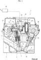
- Figure 1 of the attached drawings shows a cross-sectional view of a cylinder head of an internal combustion engine according to the art described in the document EP 0 803 642 B1 .
- the cylinder head illustrated in Figure 1 and indicated therein with reference numeral 1 is applied to an in-line four-cylinder engine, although it is understood that the variable actuating system illustrated therein is of general application.
- the head 1 comprises, for each cylinder, a cavity 2 formed in the bottom surface 3 of the head and defining the combustion chamber.
- In the cavity 2 there are two intake ducts 4, 5 (duct 5 is illustrated with a dashed line) and two discharge ducts 6 (only one of which is visible in the drawing).
- the communication of the two intake ducts 4, 5 with the combustion chamber 2 is controlled by two traditional mushroom-type intake valves 7 (only one of which is visible in the figure), each comprising a stem 8 slidably mounted in the body of the head 1.
- Each valve 7 is biassed towards the closed position by springs 9 interposed between an inner surface of the head 1 and a cup end 10 of the valve.
- the communication of the two discharge ducts 6 with the combustion chamber is controlled by two valves 70 (one of which is visible in the Figure), also of a traditional type, which also have associated return springs biassing each valve towards the closed position.
- each intake valve 7 is controlled, as will be described in the following, by a camshaft 11 rotatably mounted about an axis 12 within supports of the head 1, and comprising a plurality of cams 14 for actuating the intake valves 7 of the internal combustion engine.
- Each cam 14 that controls an intake valve 7 cooperates with the plate 15 of a tappet 16 slidably mounted along an axis 17 which, in the case of the example illustrated in the aforementioned document, is essentially directed at 90° with respect to the axis of the valve 7.
- the plate 15 is biassed against the cam 14 by a spring associated therewith.
- the tappet 16 constitutes a pumping piston, or master piston, slidably mounted within a bushing 18 carried by a body 19 of a preassembled unit 20 incorporating all the electrical and hydraulic devices associated with the actuation of the intake valves, according to what is described in detail below.
- a separate unit 20 may be provided for each cylinder of the engine.
- the master piston 16 is able to transmit a thrust to the stem 8 of the valve 7, in order to cause the valve to open against the action of the elastic means 9 by means of pressurized fluid (preferably oil from the lubrication circuit of the engine) present in a volume of pressurized fluid C to which the master piston 16 faces, and by means of a slave piston 21 slidably mounted within a cylindrical body constituted by a bushing 22, which is also carried by the body 19 of the preassembled unit 20.
- pressurized fluid preferably oil from the lubrication circuit of the engine
- the volume of pressurized fluid C associated with each intake valve 7 can be put in communication with an environment at a lower pressure, constituted by a discharge channel 23, by means of a solenoid valve 24.
- the channel 23 is configured to receive oil from the lubrication circuit of the engine, fed by the pump of the lubrication circuit, by means of a duct having one or more air purge siphons and a non-return valve (see, for example, EP-A-1 243 761 and EP-A-1 555 398 of the Applicant).
- the solenoid valve 24 can be of any known type suitable for the function illustrated herein and is controlled by electronic control means 25 according to signals S indicative of operating parameters of the engine and/or of the variable actuating system of the engine valves, such as the accelerator position and engine speed, or the temperature or viscosity of the oil in the variable actuating system of the valves.
- the solenoid of the solenoid valve 24 When the solenoid of the solenoid valve 24 is energized, the solenoid valve is closed, so as to maintain the volume of fluid C pressurized and to enable the actuation of each intake valve 7 by the respective cam 14, by means of the master piston 16, the slave piston 21 and the volume of oil contained therein.
- the solenoid valve 24 When the solenoid of the solenoid valve 24 is de-energized, the solenoid valve opens so that the volume C enters into communication with the channel 23 and the pressurized fluid present in the volume C flows into that channel. Consequently, decoupling of the cam 14 and the master piston 16 is obtained from the intake valve 7, which then returns quickly to its closed position under the action of the return springs 9.
- Each accumulator is essentially constituted by a cylindrical body within which a piston is mounted, defining a chamber of the accumulator communicating with the low pressure environment defined by the discharge channels 23, 26.
- a helical spring inside the accumulator recalls the accumulator piston towards a position wherein the volume of fluid reception inside the accumulator is minimal. If the solenoid valve 24 is opened at an instant in which the master piston 16 is in a compression state of the fluid present in volume C, part of the pressurized fluid present in volume C flows to the accumulator 270.
- the master piston 16 with the associated bushing 18, the slave piston 21 with the associated bushing 22, the solenoid valve 24 and the channels 23, 26 are carried or formed in the aforesaid body 19 of the preassembled unit 20 to make assembling of the engine quicker and easier.
- the discharge valves 70 associated with each cylinder are conventionally controlled by a respective camshaft 28 through respective tappets 29, although in principle, the application of the variable actuating system to the discharge valves is not excluded. This also applies to the present invention.
- variable volume chamber defined within the bushing 22 and facing the slave piston 21 communicates with the volume of pressurized fluid C by means of an opening 30 formed in an end wall of the bushing 22.
- This opening 30 is engaged by an end nose 31 of the piston 21 in order to implement the hydraulic braking of the movement of the valve 7 during closing, when the valve is next to the closed position, as the oil present in the variable volume chamber is forced to flow into the volume of pressurized fluid C by passing through the clearance existing between the end nose 31 and the wall of the opening 30 engaged therein.
- the chamber of pressurized fluid C and the variable volume chamber of the slave piston 21 communicate with each other by means of internal passages formed in the body of the slave piston 21 and controlled by a non-return valve 32 that only allows the flow of fluid from the pressurized volume C to the variable volume chamber of the slave piston 21.
- Various alternative embodiments of the hydraulic braking device of the slave piston 21 have been proposed in the past by the Applicant (see, for example, EP-A-1 091 097 and EP-A-1 344 900 ).
- the object of the hydraulic braking device is to avoid a strong impact (and consequent noise) of the valve 7 against its seat when the valve 7 returns rapidly to the closed position as a result of an early opening of the solenoid valve 24.
- the engine valve follows the movement of the cam (full lift).
- An early closure of the engine valve can be obtained by opening the solenoid valve 24, so as to empty the volume of pressurized fluid C and to obtain closing of the valve 7 under the action of the respective return springs 9.
- a delayed opening of the valve 7 can be achieved by delaying the closing of the solenoid valve 24, while the combination of a delayed opening with an early closing of the valve can be obtained by controlling the closing and opening of the solenoid valve during the thrust of the relative cam.
- each intake valve can be controlled in a "multi-lift" mode, that is, according to two or more repeated opening and closing "sub-cycles". In each sub-cycle, the intake valve opens and then closes completely.
- the electronic control unit is, therefore, able to obtain a change in the instant of opening and/or the instant of closing and/or the lift of the intake valve, as a function of one or more operative parameters of the engine. This allows maximum efficiency of the engine and the lowest fuel consumption, in all operating conditions.
- a hydraulic clearance compensation device (lash adjuster) can be interposed between the slave piston 21 and the stem of the engine valve.
- This solution is, for example, described in the document EP-A-1 635 045 by the same Applicant.
- Figure 1A shows, by way of example, the different lift profiles of an intake valve that can be made with the Multiair system; the outermost curve, indicated by N, represents the lift profile corresponding to the profile of the cam 14, that is, to the operating mode called "Full Lift", in which the control valve 24 never discharges the chamber C of pressurized fluid, so that the intake valve has a movement corresponding to the entire profile of the cam.
- Figure 1B shows the lift profile N, corresponding to the "Full Lift” case, and the EIVC ("Early Intake Valve Closing ”) lift profile corresponding to the case of early closing of the intake valve.
- hybrid motor-vehicles of the type in which the internal combustion engine is essentially dedicated to recharging the power supply batteries of the electric traction motor of the vehicle, makes it increasingly convenient to produce relatively simple internal combustion engines, with operation limited to a restricted portion of the engine rpm/torque diagram, located around the point of maximum efficiency of the engine.
- engines of this type there is no need for a variable actuation of the intake valves such as that achievable with the "Multiair" system.
- the same need for simplification may also exist in non-electric vehicles, where one wishes to favor simple and low-cost solutions.
- the implementation - by means of a Multiair device - of EIVC-type strategies involves a loss of energy due to that the compression energy of the return spring of the intake valves is not released.
- the energy stored by the spring is proportional to the displacement of the valve itself up to the position it reached immediately before closing: this loss, in some operating conditions, may be significant and may nullify the reduction of the suction work in the cylinder enabled by the EIVC implementation.
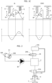
- FIG 1C schematically illustrates the above.
- a mass M compresses a spring S following the engagement of the mass M against a cam P which, in the diagram, moves to the left (the spring S corresponds to the spring 9 and the mass M corresponds to the mass of the valve 7 in Figure 1 ).
- the compression work is indicated in the lower part with a negative sign (-); during the final step of engagement with the cam, the spring returns the compression work (+) so that - in this case - there is no loss.
- Another source of loss during an EIVC actuation, consists in the volume of oil pumped by the master piston, but made to flow back towards the discharge environment without being put under pressure: the amount of this volume is given by the difference of the integral subtended by the full lift curve and the integral of the area subtended by the EIVC curve.
- this oil is not put under pressure, it represents a loss as the master piston has to push it through a series of gaps that introduce pressure drops, said loss being proportional to the volume sent to the discharge.
- the ideal objective would be to have a relatively rapid opening movement of the intake valve, maintenance of the open condition of the intake valve for a certain angular range of rotation of the crankshaft, and then a very rapid closing movement of the intake valve, limiting the movement of the intake valve as much as possible so as to reduce the compression work of the spring associated therewith.
- a primary object of the present invention is to respond to this double requirement.
- the main object of the invention is to produce a simplified version of the "Multiair" system described above, which - on the one hand - drastically reduces the constructive complexity and cost of the system, but which - on the other hand - also provides for the intake valves to be controlled in a way which would not be possible with a conventional system, with cams for mechanical actuation of the intake valves, and which is optimal for maximizing engine efficiency.
- the invention aims to produce an extremely simple and low cost actuation system for the intake valves, but capable of producing an opening profile of each intake valve with a relatively rapid opening movement, an intermediate step wherein the intake valve remains in the same open position for a certain angular range of the crankshaft rotation, and an extremely rapid closing movement of the intake valve.
- the invention relates to an actuation system for actuation of an intake valve of a cylinder of an internal combustion engine, comprising:
- control valve that controls the communication between the volume of pressurized fluid and the environment at lower pressure is not a solenoid valve as in the case of the known "Multiair" system, but is a valve controlled mechanically by a dedicated cam, arranged on the camshaft. Consequently, the system according to the invention does not require any electronic control of the communication between the volume of pressurized fluid and the environment at lower pressure, so that it is not able to perform a variable actuation of the intake valves, according to operating conditions of the engine, and in particular when engine speed and engine load vary.
- the system according to the invention is capable of producing a control of the intake valves that would not be possible with a conventional mechanical cam actuation system, and that provides, with a good approximation, as will result in more detail in the following, a profile of the intake valve lift significantly close to the ideal profile for obtaining maximum engine efficiency.
- the system according to the invention remains a hydraulic actuation system as in the case of the "Multiair” system, but replaces the electronic control provided in the "Multiair” system with a mechanical actuation of the control valve controlling the communication between the volume of fluid at high pressure and the environment at lower pressure. This is done through the provision of a dedicated cam on the same camshaft that carries the cams for actuating the intake valves.
- the device according to the invention is - in any case - compatible with other intake valve control devices, such as, for example, with timing adjusting devices - of any known type - suitable for carrying out an adjustment rotation of the entire camshaft, so as to be able to adjust the engine load.
- control valve has a valve member that is normally in a closed position of the control valve and that is configured to be pushed, directly or indirectly, by the aforesaid second cam towards an open position of the control valve.
- the control valve can be of any known type, for example of the "poppet valve” or “slide valve” type, with a movable member, which can be moved between two operating positions in which it closes and opens the communication between an inlet and an outlet of the control valve.
- the first cam is configured for opening the intake valve substantially in proximity to the Top Dead Center (TDC) of the piston movable in the cylinder with which the intake valve is associated, and for closing the intake valve in advance of the Bottom Dead Center (BDC).
- TDC Top Dead Center
- BDC Bottom Dead Center
- a limiting device is associated with the slave piston of the intake valve actuation system, which puts a hydraulic chamber, containing a volume of fluid that operates the slave piston, to discharge when the slave piston has moved through a predetermined distance, in such a way that the intake valve has a maximum lift that is reduced with respect to the theoretical maximum lift determined by said first cam, this maximum lift being kept constant through a determined angular range of the crankshaft rotation, up to the crank angle value at which the intake valve suddenly closes, due to the opening of the control valve.
- the mechanical connection between the second cam and the movable member of the control valve is configured in such a way that the movable member of the control valve begins to move towards its open position after an initial lifting stage of said second cam.
- each intake valve is associated with a respective actuation system, with a respective first cam and a respective control valve: in this way it is possible to differentiate the actuation laws of the intake valves.
- the asymmetrical actuation of the intake valves in particular, at low engine speeds, provides the establishment of swirl motions in the combustion chamber, which favor the mixing of the air charge with the fuel injected through a direct injection, and thus provide a reduction of particulates and HC.
- each of the two intake valves of the same cylinder is associated with a respective second cam for the mechanical control of the respective control valve, even if the possibility of providing a single second cam for actuation of the two control valves associated with the two intake valves of the same cylinder is not excluded.
- the ratio between the diameter of the master piston and the diameter of the slave piston (which is associated with the hydraulic brake of the corresponding intake valve) may be optimized to reduce said excursion by maximizing the opening speed of the intake valve.
- a single first cam and a single second cam can be provided to simultaneously control the two intake valves associated with the same cylinder.
- a single master piston controls the two slave pistons of the intake valves by means of a single volume of pressurized fluid that can be discharged through a single control valve.
- the diameters of the slave pistons associated with the intake valves may have different values, so as to differentiate the lift profiles of the two intake valves.
- different limiting devices associated with the two slave pistons may be provided, so as to differentiate the maximum lift of the two intake valves.
- the return springs towards the closed position of the two intake valves of each cylinder may have different characteristics, so as to differentiate the closing speed of the two intake valves.
- the cams are configured and arranged in such a way that one of the two intake valves of each cylinder opens after that the other intake valve has already been opened and closed.
- Figure 2 shows an intake valve 7 that is operated by a slave piston 21, which receives pressurized fluid from a pressurized fluid chamber C following the pumping action of a master piston 16, which is mechanically driven, directly or indirectly, by a cam 14A of a camshaft 11.
- a first fundamental difference with respect to the "Multiair" system described above with reference to Figure 1 lies in that the control valve 24, which controls the communication between the pressurized fluid chamber C and the reduced pressure environment, communicating with the pressure accumulator 270, is not an electrically-operated valve.
- the valve 24 has a movable member 24A which is mechanically controlled, directly or indirectly, by a dedicated cam 14B arranged on the cam shaft 11 carrying the cams 11A for actuating the intake valves.
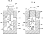
- FIGS 3, 4 show the closed condition and the open condition of an examplary embodiment of the mechanical valve 24.
- the valve 24 is a "poppet valve", with a valve body 240 having an axial cavity 241 communicating with two openings 242, 243 connected, respectively, to the pressurized fluid chamber C and to the reduced pressure environment 270.
- a dividing wall 242 Inside the cavity 241 there is a dividing wall 242 with an opening acting as a valve seat for a ball 245 pushed by a spring 246 towards a closed position of the valve seat.
- a movable member 247 having a pin 248 configured to push the ball 245 towards an opening position of the valve seat, against the action of the spring 246 ( Figure 4 ) as a result of a downward movement (with reference to the figures) of the movable member 247.
- the movable member 247 has an end out of the valve body, indicated by 248, which is actuated, directly or indirectly (by means of a mechanical transmission of any known type) by the second cam 14B.
- valve 24 for the control valve 24 is given here purely by way of example.
- the configuration of the valve 24 could also be completely different, for example, it could be that of a slide valve or that of any other valve of a known type capable of opening or closing the communication between two ways by means of a movable member having two operating positions.
- the second cam 14B acts in the direction of moving the movable member of the valve towards one of its two operating positions (towards the open position in the case of the preferred example described herein).
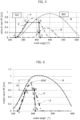
- Figure 5 refers to a preferred examplary embodiment of the invention.
- the line N shows the lift diagram of an intake valve in a conventional mechanical actuation system of the intake valves.
- the diagram N shows the displacement of the valve as the crank angle varies.
- the values of 360° and 540° in the diagram of Figure 5 correspond to the TDC and BDC positions of the piston in the cylinder with which the intake valve is associated.
- the diagrams A and B show the profiles of the first cam 14A and of the second cam 14B, represented as a variation of the radial dimension of the cam as a function of the engine crank angle.
- the first cam 14A causes an opening of the intake valve associated therewith substantially at the TDC and would cause the intake valve to close with a certain advance with respect to the BDC, in the example at about 490°.
- the second cam 14B begins to intervene, causing a displacement of the movable member of the control valve 24 into its open position, which causes a rapid closing of the intake valve, in advance of the closing that would be dictated by the profile of the first cam 14A.
- the diagram X indicates the lift profile of the intake valve, which can be obtained with the system according to the invention. As can be seen, from a point P at which the intake valve begins to open, up to a point Q, the intake valve opens due to the hydraulic actuation by the master piston 16 caused by the first cam 14A.
- the slope of the initial section of curve X can be steeper than the slope of the initial section of the curve (corresponding to the cam 14A), by suitably dimensioning the ratio of the diameters of the master piston 16 and of the slave piston 21 (with which the hydraulic brake of the intake valve is associated).
- the slave cylinder in which the slave piston 21 is movable is associated with a discharge port 21A, communicating with the low pressure environment 270, which puts the volume of fluid that pushes the slave piston 21 to discharge when the slave piston 21 has completed a stroke H, corresponding to an identical opening stroke of the intake valve 7. Therefore, at point Q, before that the intake valve 7 reaches the maximum lift that would derive from the profile A of the first cam 14A, the intake valve 7 stops and remains in this opened position through a determined angular range of rotation of the crankshaft (in the example from about 400° to about 450°) up to a point R.
- the mechanical transmission between the second cam 14B and the movable member of the control valve 24 is configured in such a way that the movable member 24A begins to move towards its open position only after the second cam 14B has reached its operating point Z in figure 5 , corresponding to a lift which in the example is about 0.2 cm.
- the pressurized fluid discharges into the environment at reduced pressure and the intake valve 7 closes rapidly: this step corresponds to the section RS in the diagram X, which is almost vertical.
- the system according to the invention is therefore capable of producing a substantially squared lift diagram X, with a relatively steep opening section, an intermediate section with constant opening, and an extremely steep closing section, which is optimal for the purpose of improving the efficiency of the engine and in particular for the purpose of increasing the combustion speed in the cylinder.
- Figure 6 shows the advantages of the invention with respect to the case of an EIVC actuation with the Multiair system: the maximum opening of the valve is reduced by ⁇ x and consequently the compression work of the spring 9 is lower and also lower is the compression work which is lost when the motion of the valve is disconnected from the motion of the master piston 16, by putting the volume C to discharge. Furthermore, the volume of the total oil pumped by the master piston 16 (area subtended by curve A) is significantly reduced compared to that pumped in the Multiair case (area subtended by curve N) and, therefore, the pressure drop associated with the loss of said volumes through the different channels of the hydraulic circuit is significantly reduced.
- an actuation system of the type described above can be associated with each of said intake valves, with a respective first cam, a respective second cam, a respective master piston and a respective slave piston, as well as a respective control valve: this configuration allows asymmetrical actuation of the intake valves and the possibility of generating air motions particularly favorable to improving the mixing of air and fuel and to increasing turbulent kinetic energy.
- a respective second cam is also associated with each intake valve for the mechanical actuation of the respective control valve, but the possibility of providing a single second cam 14B to control the two control valves 24 associated with the two intake valves of the same cylinder is not excluded.
- the engine with a device, of a known type, with a cam 14A having an additional portion of different profile axially adjacent to the main portion and which can be activated under certain operating conditions of the engine, so that the master piston 16 is actuated by this additional portion, so as to move the intake valve according to a curve of the type of curve N of Figure 5 : in this case, therefore, the second cam 14B does not intervene and the closure takes place in a traditional manner.
- a single first cam and a single second cam may also be provided to simultaneously control the two intake valves associated with the same cylinder.
- a single master piston controls the two slave pistons of the intake valves by means of a single volume of pressurized fluid that can be discharged through a single control valve.
- the diameters of the slave pistons associated with the intake valves may have different values, so as to differentiate the lift profiles of the two intake valves.
- different limiting devices associated with the two slave pistons may be provided, so as to differentiate the maximum lift of the two intake valves.
- the return springs biassing the two intake valves towards the closed position may have different characteristics, so as to differentiate the closing speed of the two intake valves.
- the cams are configured and arranged in such a way that one of the two intake valves of each cylinder opens after that the other intake valve has already been opened and closed.
Landscapes
- Engineering & Computer Science (AREA)
- Mechanical Engineering (AREA)
- General Engineering & Computer Science (AREA)
- Valve Device For Special Equipments (AREA)
Claims (16)
- Betätigungssystem zur Betätigung eines Einlassventils, das mit einem Zylinder in einer Brennkraftmaschine verbunden ist, umfassend:- einen Geberkolben (16), der, direkt oder indirekt, von einem Nocken (14) einer Nockenwelle (11) der Brennkraftmaschine gesteuert wird,- einen Nehmerkolben (21), der das Einlassventil (7) betätigt und von dem Geberkolben (16) mithilfe eines Volumens eines druckbeaufschlagten Fluids (C), das zwischen den Geberkolben (16) und den Nehmerkolben (21) geschaltet ist, hydraulisch gesteuert wird,- wobei das Einlassventil (7) von mindestens einer Feder (9) in Richtung einer geschlossenen Stellung vorgespannt wird, und- ein Steuerventil (24), das die Verbindung zwischen dem Volumen eines druckbeaufschlagten Fluids (C) und einer Umgebung mit einem niedrigeren Druck (23) steuert, die mit einem Fluidspeicher (270) verbunden ist,- derart, dass:- wenn das Steuerventil (24) die Verbindung geschlossen hält, das Einlassventil (7) empfindlich gegenüber der Bewegung des ersten Nockens (14A) ist, während- wenn das Steuerventil (24) die Verbindung öffnet, das Fluid aus dem Volumen eines druckbeaufschlagten Fluids (C) in die Umgebung mit niedrigerem Druck (270) entladen wird, sodass das Einlassventil (7) von der Feder (9) in Richtung der geschlossenen Stellung vorgespannt wird und gegenüber der Bewegung des ersten Nockens (14A) unempfindlich bleibt,- wobei das System dadurch gekennzeichnet ist, dass das Steuerventil (24) von einem zweiten Nocken (14B) mechanisch gesteuert wird, der von der Nockenwelle (11) getragen wird und die alleinige Funktion hat, das Steuerventil (24) zu steuern, und dadurch, dass der zweite Nocken (14B) derart gestaltet und auf der Nockenwelle (11) winklig positioniert ist, dass er das Öffnen des Steuerventils (24) und das resultierende schlagartige Schließen des Einlassventils (7) im Vorgriff auf das Schließen des Einlassventils bewirkt, das durch den ersten Nocken (14A) bedingt würde.
- System nach Anspruch 1, dadurch gekennzeichnet, dass das Steuerventil (24) ein Ventilelement (24A) aufweist, das normalerweise in einer geschlossenen Stellung des Steuerventils ist und das dazu eingerichtet ist, direkt oder indirekt, von dem zweiten Nocken (14B) in Richtung einer Öffnungsstellung des Steuerventils (24) gedrückt zu werden.
- System nach Anspruch 1, dadurch gekennzeichnet, dass der erste Nocken (14A) dazu eingerichtet ist, das Einlassventil (7) im Wesentlichen in der Nähe des OT des Kolbens, der in dem Zylinder beweglich ist, mit dem das Einlassventil (7) verbunden ist, zu öffnen und das Einlassventil (7) vor dem UT zu schließen.
- System nach Anspruch 1, dadurch gekennzeichnet, dass eine Begrenzungsvorrichtung (21A), die mit dem Nehmerkolben (21) verbunden ist, eine Hydraulikkammer, die ein Fluidvolumen enthält, das den Nehmerkolben (21) aktiviert, zum Entladen bringt, wenn sich der Nehmerkolben um eine vorbestimmte Strecke (H) bewegt hat, sodass das Einlassventil (7) einen maximalen Hub hat, der gegenüber dem theoretischen maximalen Hub reduziert ist, der von dem ersten Nocken (14A) bestimmt wird, wobei der maximale Hub des Einlassventils über einen Winkelbereich der Kurbelwellendrehung bis zu einem Wert des Kurbelwinkels konstant gehalten wird, bei dem sich das Einlassventil (7) aufgrund des Öffnens des Steuerventils (24) schlagartig schließt.
- System nach Anspruch 1, dadurch gekennzeichnet, dass die mechanische Verbindung zwischen dem zweiten Nocken (14B) und einem beweglichen Element (248) des Steuerventil (24) derart gestaltet ist, dass sich das bewegliche Element (248) nach einer Anfangshubphase des zweiten Nockens (14B) in Richtung seiner geöffneten Stellung zu bewegen beginnt.
- System nach Anspruch 1, dadurch gekennzeichnet, dass zwei Einlassventile (7) mit jedem Zylinder der Maschine verbunden sind und dass jedes Einlassventil (7) mit einem jeweiligen Betätigungssystem mit einem jeweiligen ersten Nocken (14A) und einem jeweiligen Steuerventil (24) verbunden ist.
- System nach Anspruch 6, dadurch gekennzeichnet, dass ein jeweiliger zweiter Nocken (14B) für jedes der zwei Einlassventile (7) vorgesehen ist, die mit jedem Zylinder verbunden sind.
- System nach Anspruch 6, dadurch gekennzeichnet, dass ein einziger zweiter Nocken (14B) vorgesehen ist, der den zwei Einlassventilen (7) gemeinsam ist, die mit jedem Zylinder verbunden sind.
- System nach Anspruch 1, dadurch gekennzeichnet, dass zwei Einlassventile (7) mit jedem Zylinder der Maschine verbunden sind und dass ein einziger erster Nocken (14A) und ein einziger zweiter Nocken (14B) vorgesehen sind, um die zwei Einlassventile (7) simultan zu steuern, die mit demselben Zylinder verbunden sind.
- System nach Anspruch 4, dadurch gekennzeichnet, dass zwei Einlassventile (7) mit jedem Zylinder der Maschine verbunden sind und dass die Durchmesser der Nehmerkolben (21), die mit den Einlassventilen verbunden sind, verschiedene Werte haben, damit sich die Hubprofile der zwei Einlassventile unterscheiden.
- System nach Anspruch 1, dadurch gekennzeichnet, dass zwei Einlassventile (7) mit jedem Zylinder der Maschine verbunden sind und dass verschiedene Begrenzungsvorrichtungen (21A) mit den Nehmerkolben (21) der zwei Einlassventile verbunden sind, damit sich der maximale Hub der zwei Einlassventile unterscheidet.
- System nach Anspruch 1, dadurch gekennzeichnet, dass zwei Einlassventile (7) mit jedem Zylinder der Maschine verbunden sind und dass die Federn (9), die die zwei Einlassventile (7) in Richtung der geschlossenen Stellung vorspannen, unterschiedliche Kennlinien haben, damit sich die Schließgeschwindigkeit der zwei Einlassventile unterscheidet.
- System nach Anspruch 6, dadurch gekennzeichnet, dass die zwei ersten Nocken (14A) derart gestaltet und eingerichtet sind, dass sich eines der zwei Einlassventile (7) von jedem Zylinder öffnet, nachdem das andere Einlassventil (7) bereits geöffnet und geschlossen wurde.
- System nach Anspruch 1, dadurch gekennzeichnet, dass es eine Zeitsteuerungsvorrichtung umfasst, um die Zeitsteuerung der Nockenwelle (11) zu ändern.
- System nach Anspruch 1, dadurch gekennzeichnet, dass der erste Nocken eines an sich bekannten Typs ist, der Abschnitte mit unterschiedlichen Nockenprofilen umfasst, die axial aneinander angrenzen und wählbar sind, um den Betätigungsmodus der Einlassventile zwischen einem Betätigungsmodus mit früherem schnellen Schließen und einem herkömmlichen Betätigungsmodus zu ändern.
- System nach Anspruch 1, dadurch gekennzeichnet, dass zwei Einlassventile (7) mit jedem Zylinder der Maschine verbunden sind und dass nur eines der Einlassventile von dem System betätigt wird, während das andere Einlassventil von einem jeweiligen Nocken mithilfe einer herkömmlichen mechanischen Betätigungsvorrichtung oder mithilfe einer elektronisch gesteuerten hydraulischen Vorrichtung des Typs "Multiair" betätigt wird.
Priority Applications (2)
| Application Number | Priority Date | Filing Date | Title |
|---|---|---|---|
| EP21168009.5A EP4074945B1 (de) | 2021-04-13 | 2021-04-13 | System zur betätigung eines einlassventils einer brennkraftmaschine |
| PCT/IB2022/052884 WO2022219440A1 (en) | 2021-04-13 | 2022-03-29 | A system for actuation of an intake valve of an internal combustion engine |
Applications Claiming Priority (1)
| Application Number | Priority Date | Filing Date | Title |
|---|---|---|---|
| EP21168009.5A EP4074945B1 (de) | 2021-04-13 | 2021-04-13 | System zur betätigung eines einlassventils einer brennkraftmaschine |
Publications (2)
| Publication Number | Publication Date |
|---|---|
| EP4074945A1 EP4074945A1 (de) | 2022-10-19 |
| EP4074945B1 true EP4074945B1 (de) | 2023-05-31 |
Family
ID=76034403
Family Applications (1)
| Application Number | Title | Priority Date | Filing Date |
|---|---|---|---|
| EP21168009.5A Active EP4074945B1 (de) | 2021-04-13 | 2021-04-13 | System zur betätigung eines einlassventils einer brennkraftmaschine |
Country Status (2)
| Country | Link |
|---|---|
| EP (1) | EP4074945B1 (de) |
| WO (1) | WO2022219440A1 (de) |
Families Citing this family (2)
| Publication number | Priority date | Publication date | Assignee | Title |
|---|---|---|---|---|
| IT202200026241A1 (it) | 2022-12-21 | 2024-06-21 | Fiat Ricerche | "Sistema per l'azionamento di una valvola di aspirazione di un motore a combustione interna" |
| IT202400001431A1 (it) * | 2024-01-25 | 2025-07-25 | Fiat Ricerche | "motore a combustione interna con azionamento variabile delle valvole di aspirazione, ad efficienza migliorata ai bassi carichi motore, e relativo procedimento di controllo" |
Family Cites Families (11)
| Publication number | Priority date | Publication date | Assignee | Title |
|---|---|---|---|---|
| IT1285853B1 (it) | 1996-04-24 | 1998-06-24 | Fiat Ricerche | Motore a combustione interna con valvole ad azionamento variabile. |
| IT1307361B1 (it) | 1999-10-06 | 2001-11-06 | Fiat Ricerche | Perfezionamenti ai motori a combustione interna con valvole adazionamento variabile. |
| ITTO20010269A1 (it) | 2001-03-23 | 2002-09-23 | Fiat Ricerche | Motore a combustione interna, con sistema idraulico di azionamento variabile delle valvole, e mezzi di compensazione delle variazioni di vol |
| ITTO20020234A1 (it) | 2002-03-15 | 2003-09-15 | Fiat Ricerche | Motore pluricilindrico a combustione interna con dispositivo idraulico a controllo elettronico per l'azionamento variabile delle valvole e d |
| DE602004004997T2 (de) | 2004-01-16 | 2007-11-08 | C.R.F. S.C.P.A. | Brennkraftmaschine mit einer einzigen obenliegenden Nockenwelle zur mechanischen Steuerung der Auslassventile und zur elektrohydraulischen Steuerung der Einlassventile |
| ATE349602T1 (de) | 2004-09-14 | 2007-01-15 | Fiat Ricerche | Brennkraftmaschine mit variabel angesteuerten ventilen, welche jeweils mit einem hydraulischen stö el au erhalb des jeweiligen aktors versehen sind |
| ATE377140T1 (de) | 2005-05-24 | 2007-11-15 | Fiat Ricerche | Vorrichtung und verfahren zur kontrolle der last und der verbrennung in einer brennkraftmaschine durch eine ventilbetätigung mit mehrfachem ventilhub pro zyklus |
| EP2597276B1 (de) * | 2011-11-24 | 2014-04-16 | C.R.F. Società Consortile per Azioni | Brennkraftmaschine mit variablem Ventiltrieb mit einem Drei-Wege-Solenoidventil |
| DE102012214645A1 (de) * | 2012-08-17 | 2014-02-20 | Mahle International Gmbh | Brennkraftmaschine mit zwei gegenläufigen Nockenwellen |
| EP2796675B1 (de) * | 2013-04-26 | 2016-11-23 | C.R.F. Società Consortile per Azioni | Brennkraftmaschine mit Ventiltrieb zur variablen Betätigung der Einlassventile mit Drei-Weg Solenoidventilen und Verfahren zur Kontrolle dieser Brennkraftmaschine in einem "einzigen-Hub" Modus |
| EP3181842B1 (de) * | 2015-12-17 | 2019-06-19 | C.R.F. Società Consortile per Azioni | System und verfahren zur variablen betätigung eines ventils einer brennkraftmaschine mit einem elektrisch betätigten steuerventil mit verbesserter steuerung |
-
2021
- 2021-04-13 EP EP21168009.5A patent/EP4074945B1/de active Active
-
2022
- 2022-03-29 WO PCT/IB2022/052884 patent/WO2022219440A1/en not_active Ceased
Also Published As
| Publication number | Publication date |
|---|---|
| WO2022219440A1 (en) | 2022-10-20 |
| EP4074945A1 (de) | 2022-10-19 |
Similar Documents
| Publication | Publication Date | Title |
|---|---|---|
| US5526784A (en) | Simultaneous exhaust valve opening braking system | |
| US10830159B2 (en) | Valve-actuating device for varying the valve lift | |
| EP2325460B1 (de) | Kompaktes Totgangsystem für variable Ventilbetätigung | |
| EP0803642B1 (de) | Brennkraftmaschine mit verstellbarem Ventilantrieb | |
| JP4154622B2 (ja) | ピストンエンジンの動作中において有効排気量および/または容積比を変更するための装置 | |
| EP2578871B1 (de) | Verfahren zur Steuerung einer Brennkraftmaschine mit einem variablen Einlassventilsystem. | |
| EP1674673A1 (de) | Brennkraftmaschine mit hydraulischen variablen Ventilen | |
| WO2004081352A1 (en) | Modal variable valve actuation system for internal combustion engine and method for operating the same | |
| US12247502B2 (en) | Multi-cylinder internal combustion engine, with cylinders equipped with intake valve variable actuation systems having hydraulic circuits which cross each other | |
| US10151221B2 (en) | System and method for variable actuation of a valve of an internalcombustion engine, with an electrically operated control valve having an improved control | |
| WO2022219440A1 (en) | A system for actuation of an intake valve of an internal combustion engine | |
| EP1635045A1 (de) | Brennkraftmaschine mit variabel angesteuerten Ventilen, welche jeweils mit einem hydraulischen Stö el au erhalb des jeweiligen Aktors versehen sind | |
| US11207964B2 (en) | Method for controlling an internal combustion engine | |
| EP3156619B1 (de) | System und verfahren zur variablen betätigung eines ventils einer brennkraftmaschine mit einer vorrichtung zur dämpfung von druckschwingungen | |
| WO2014060645A1 (en) | Gas exchange valve arrangement | |
| EP2511504A1 (de) | Mehrzylinder-Verbrennungsmotor mit einem System zur variablen Betätigung der Einlassventile und mit Ausgleich der Unterschiede des von den Zylindern verursachten Drehmoments und in diesem Motor implementiertes Steuerverfahren | |
| WO2024134333A1 (en) | A system for actuating an intake valve of an internal combustion engine | |
| US20040065285A1 (en) | Variable engine valve actuator | |
| US12270351B2 (en) | Reversing method for a vehicle powertrain | |
| US20190162085A1 (en) | System and method for actuating an engine valve of an internal combustion engine | |
| WO2025215431A1 (en) | Internal combustion engine with two intake valves per cylinder controlled by a mechanical actuation system and an electronically controlled hydraulic actuation system respectively | |
| EP4735741A1 (de) | Brennkraftmaschine mit variabler einlassventilbetätigung, stiefelprofilnocken und motorsteuerungsverfahren | |
| WO2025181590A1 (en) | Internal combustion engine with variable actuation intake valves and with cylinders controlled to operate independently with ultra-lean combustion or stoichiometric combustion, and a control method therefor | |
| CN116792177A (zh) | 可变气门升程调节装置及方法、发动机、车辆 |
Legal Events
| Date | Code | Title | Description |
|---|---|---|---|
| PUAI | Public reference made under article 153(3) epc to a published international application that has entered the european phase |
Free format text: ORIGINAL CODE: 0009012 |
|
| STAA | Information on the status of an ep patent application or granted ep patent |
Free format text: STATUS: REQUEST FOR EXAMINATION WAS MADE |
|
| 17P | Request for examination filed |
Effective date: 20220317 |
|
| AK | Designated contracting states |
Kind code of ref document: A1 Designated state(s): AL AT BE BG CH CY CZ DE DK EE ES FI FR GB GR HR HU IE IS IT LI LT LU LV MC MK MT NL NO PL PT RO RS SE SI SK SM TR |
|
| GRAP | Despatch of communication of intention to grant a patent |
Free format text: ORIGINAL CODE: EPIDOSNIGR1 |
|
| STAA | Information on the status of an ep patent application or granted ep patent |
Free format text: STATUS: GRANT OF PATENT IS INTENDED |
|
| INTG | Intention to grant announced |
Effective date: 20221206 |
|
| GRAS | Grant fee paid |
Free format text: ORIGINAL CODE: EPIDOSNIGR3 |
|
| GRAA | (expected) grant |
Free format text: ORIGINAL CODE: 0009210 |
|
| STAA | Information on the status of an ep patent application or granted ep patent |
Free format text: STATUS: THE PATENT HAS BEEN GRANTED |
|
| AK | Designated contracting states |
Kind code of ref document: B1 Designated state(s): AL AT BE BG CH CY CZ DE DK EE ES FI FR GB GR HR HU IE IS IT LI LT LU LV MC MK MT NL NO PL PT RO RS SE SI SK SM TR |
|
| REG | Reference to a national code |
Ref country code: GB Ref legal event code: FG4D Ref country code: CH Ref legal event code: EP |
|
| REG | Reference to a national code |
Ref country code: DE Ref legal event code: R096 Ref document number: 602021002516 Country of ref document: DE |
|
| REG | Reference to a national code |
Ref country code: AT Ref legal event code: REF Ref document number: 1571034 Country of ref document: AT Kind code of ref document: T Effective date: 20230615 |
|
| REG | Reference to a national code |
Ref country code: IE Ref legal event code: FG4D |
|
| REG | Reference to a national code |
Ref country code: LT Ref legal event code: MG9D |
|
| REG | Reference to a national code |
Ref country code: NL Ref legal event code: MP Effective date: 20230531 |
|
| REG | Reference to a national code |
Ref country code: AT Ref legal event code: MK05 Ref document number: 1571034 Country of ref document: AT Kind code of ref document: T Effective date: 20230531 |
|
| PG25 | Lapsed in a contracting state [announced via postgrant information from national office to epo] |
Ref country code: SE Free format text: LAPSE BECAUSE OF FAILURE TO SUBMIT A TRANSLATION OF THE DESCRIPTION OR TO PAY THE FEE WITHIN THE PRESCRIBED TIME-LIMIT Effective date: 20230531 Ref country code: NO Free format text: LAPSE BECAUSE OF FAILURE TO SUBMIT A TRANSLATION OF THE DESCRIPTION OR TO PAY THE FEE WITHIN THE PRESCRIBED TIME-LIMIT Effective date: 20230831 Ref country code: ES Free format text: LAPSE BECAUSE OF FAILURE TO SUBMIT A TRANSLATION OF THE DESCRIPTION OR TO PAY THE FEE WITHIN THE PRESCRIBED TIME-LIMIT Effective date: 20230531 Ref country code: AT Free format text: LAPSE BECAUSE OF FAILURE TO SUBMIT A TRANSLATION OF THE DESCRIPTION OR TO PAY THE FEE WITHIN THE PRESCRIBED TIME-LIMIT Effective date: 20230531 |
|
| PG25 | Lapsed in a contracting state [announced via postgrant information from national office to epo] |
Ref country code: RS Free format text: LAPSE BECAUSE OF FAILURE TO SUBMIT A TRANSLATION OF THE DESCRIPTION OR TO PAY THE FEE WITHIN THE PRESCRIBED TIME-LIMIT Effective date: 20230531 Ref country code: PL Free format text: LAPSE BECAUSE OF FAILURE TO SUBMIT A TRANSLATION OF THE DESCRIPTION OR TO PAY THE FEE WITHIN THE PRESCRIBED TIME-LIMIT Effective date: 20230531 Ref country code: NL Free format text: LAPSE BECAUSE OF FAILURE TO SUBMIT A TRANSLATION OF THE DESCRIPTION OR TO PAY THE FEE WITHIN THE PRESCRIBED TIME-LIMIT Effective date: 20230531 Ref country code: LV Free format text: LAPSE BECAUSE OF FAILURE TO SUBMIT A TRANSLATION OF THE DESCRIPTION OR TO PAY THE FEE WITHIN THE PRESCRIBED TIME-LIMIT Effective date: 20230531 Ref country code: LT Free format text: LAPSE BECAUSE OF FAILURE TO SUBMIT A TRANSLATION OF THE DESCRIPTION OR TO PAY THE FEE WITHIN THE PRESCRIBED TIME-LIMIT Effective date: 20230531 Ref country code: IS Free format text: LAPSE BECAUSE OF FAILURE TO SUBMIT A TRANSLATION OF THE DESCRIPTION OR TO PAY THE FEE WITHIN THE PRESCRIBED TIME-LIMIT Effective date: 20230930 Ref country code: HR Free format text: LAPSE BECAUSE OF FAILURE TO SUBMIT A TRANSLATION OF THE DESCRIPTION OR TO PAY THE FEE WITHIN THE PRESCRIBED TIME-LIMIT Effective date: 20230531 Ref country code: GR Free format text: LAPSE BECAUSE OF FAILURE TO SUBMIT A TRANSLATION OF THE DESCRIPTION OR TO PAY THE FEE WITHIN THE PRESCRIBED TIME-LIMIT Effective date: 20230901 |
|
| PG25 | Lapsed in a contracting state [announced via postgrant information from national office to epo] |
Ref country code: FI Free format text: LAPSE BECAUSE OF FAILURE TO SUBMIT A TRANSLATION OF THE DESCRIPTION OR TO PAY THE FEE WITHIN THE PRESCRIBED TIME-LIMIT Effective date: 20230531 |
|
| PG25 | Lapsed in a contracting state [announced via postgrant information from national office to epo] |
Ref country code: SK Free format text: LAPSE BECAUSE OF FAILURE TO SUBMIT A TRANSLATION OF THE DESCRIPTION OR TO PAY THE FEE WITHIN THE PRESCRIBED TIME-LIMIT Effective date: 20230531 |
|
| PG25 | Lapsed in a contracting state [announced via postgrant information from national office to epo] |
Ref country code: SM Free format text: LAPSE BECAUSE OF FAILURE TO SUBMIT A TRANSLATION OF THE DESCRIPTION OR TO PAY THE FEE WITHIN THE PRESCRIBED TIME-LIMIT Effective date: 20230531 Ref country code: SK Free format text: LAPSE BECAUSE OF FAILURE TO SUBMIT A TRANSLATION OF THE DESCRIPTION OR TO PAY THE FEE WITHIN THE PRESCRIBED TIME-LIMIT Effective date: 20230531 Ref country code: RO Free format text: LAPSE BECAUSE OF FAILURE TO SUBMIT A TRANSLATION OF THE DESCRIPTION OR TO PAY THE FEE WITHIN THE PRESCRIBED TIME-LIMIT Effective date: 20230531 Ref country code: PT Free format text: LAPSE BECAUSE OF FAILURE TO SUBMIT A TRANSLATION OF THE DESCRIPTION OR TO PAY THE FEE WITHIN THE PRESCRIBED TIME-LIMIT Effective date: 20231002 Ref country code: EE Free format text: LAPSE BECAUSE OF FAILURE TO SUBMIT A TRANSLATION OF THE DESCRIPTION OR TO PAY THE FEE WITHIN THE PRESCRIBED TIME-LIMIT Effective date: 20230531 Ref country code: DK Free format text: LAPSE BECAUSE OF FAILURE TO SUBMIT A TRANSLATION OF THE DESCRIPTION OR TO PAY THE FEE WITHIN THE PRESCRIBED TIME-LIMIT Effective date: 20230531 Ref country code: CZ Free format text: LAPSE BECAUSE OF FAILURE TO SUBMIT A TRANSLATION OF THE DESCRIPTION OR TO PAY THE FEE WITHIN THE PRESCRIBED TIME-LIMIT Effective date: 20230531 |
|
| REG | Reference to a national code |
Ref country code: DE Ref legal event code: R097 Ref document number: 602021002516 Country of ref document: DE |
|
| PLBE | No opposition filed within time limit |
Free format text: ORIGINAL CODE: 0009261 |
|
| STAA | Information on the status of an ep patent application or granted ep patent |
Free format text: STATUS: NO OPPOSITION FILED WITHIN TIME LIMIT |
|
| PG25 | Lapsed in a contracting state [announced via postgrant information from national office to epo] |
Ref country code: SI Free format text: LAPSE BECAUSE OF FAILURE TO SUBMIT A TRANSLATION OF THE DESCRIPTION OR TO PAY THE FEE WITHIN THE PRESCRIBED TIME-LIMIT Effective date: 20230531 |
|
| 26N | No opposition filed |
Effective date: 20240301 |
|
| PG25 | Lapsed in a contracting state [announced via postgrant information from national office to epo] |
Ref country code: SI Free format text: LAPSE BECAUSE OF FAILURE TO SUBMIT A TRANSLATION OF THE DESCRIPTION OR TO PAY THE FEE WITHIN THE PRESCRIBED TIME-LIMIT Effective date: 20230531 |
|
| PG25 | Lapsed in a contracting state [announced via postgrant information from national office to epo] |
Ref country code: BG Free format text: LAPSE BECAUSE OF FAILURE TO SUBMIT A TRANSLATION OF THE DESCRIPTION OR TO PAY THE FEE WITHIN THE PRESCRIBED TIME-LIMIT Effective date: 20230531 |
|
| PG25 | Lapsed in a contracting state [announced via postgrant information from national office to epo] |
Ref country code: MC Free format text: LAPSE BECAUSE OF FAILURE TO SUBMIT A TRANSLATION OF THE DESCRIPTION OR TO PAY THE FEE WITHIN THE PRESCRIBED TIME-LIMIT Effective date: 20230531 |
|
| PG25 | Lapsed in a contracting state [announced via postgrant information from national office to epo] |
Ref country code: MC Free format text: LAPSE BECAUSE OF FAILURE TO SUBMIT A TRANSLATION OF THE DESCRIPTION OR TO PAY THE FEE WITHIN THE PRESCRIBED TIME-LIMIT Effective date: 20230531 Ref country code: BG Free format text: LAPSE BECAUSE OF FAILURE TO SUBMIT A TRANSLATION OF THE DESCRIPTION OR TO PAY THE FEE WITHIN THE PRESCRIBED TIME-LIMIT Effective date: 20230531 |
|
| REG | Reference to a national code |
Ref country code: CH Ref legal event code: PL |
|
| PG25 | Lapsed in a contracting state [announced via postgrant information from national office to epo] |
Ref country code: LU Free format text: LAPSE BECAUSE OF NON-PAYMENT OF DUE FEES Effective date: 20240413 |
|
| REG | Reference to a national code |
Ref country code: BE Ref legal event code: MM Effective date: 20240430 |
|
| PG25 | Lapsed in a contracting state [announced via postgrant information from national office to epo] |
Ref country code: LU Free format text: LAPSE BECAUSE OF NON-PAYMENT OF DUE FEES Effective date: 20240413 |
|
| PG25 | Lapsed in a contracting state [announced via postgrant information from national office to epo] |
Ref country code: BE Free format text: LAPSE BECAUSE OF NON-PAYMENT OF DUE FEES Effective date: 20240430 |
|
| PG25 | Lapsed in a contracting state [announced via postgrant information from national office to epo] |
Ref country code: BE Free format text: LAPSE BECAUSE OF NON-PAYMENT OF DUE FEES Effective date: 20240430 Ref country code: CH Free format text: LAPSE BECAUSE OF NON-PAYMENT OF DUE FEES Effective date: 20240430 |
|
| PG25 | Lapsed in a contracting state [announced via postgrant information from national office to epo] |
Ref country code: IE Free format text: LAPSE BECAUSE OF NON-PAYMENT OF DUE FEES Effective date: 20240413 |
|
| PG25 | Lapsed in a contracting state [announced via postgrant information from national office to epo] |
Ref country code: CY Free format text: LAPSE BECAUSE OF FAILURE TO SUBMIT A TRANSLATION OF THE DESCRIPTION OR TO PAY THE FEE WITHIN THE PRESCRIBED TIME-LIMIT; INVALID AB INITIO Effective date: 20210413 |
|
| PG25 | Lapsed in a contracting state [announced via postgrant information from national office to epo] |
Ref country code: HU Free format text: LAPSE BECAUSE OF FAILURE TO SUBMIT A TRANSLATION OF THE DESCRIPTION OR TO PAY THE FEE WITHIN THE PRESCRIBED TIME-LIMIT; INVALID AB INITIO Effective date: 20210413 |
|
| GBPC | Gb: european patent ceased through non-payment of renewal fee |
Effective date: 20250413 |
|
| PG25 | Lapsed in a contracting state [announced via postgrant information from national office to epo] |
Ref country code: GB Free format text: LAPSE BECAUSE OF NON-PAYMENT OF DUE FEES Effective date: 20250413 |
|
| PGFP | Annual fee paid to national office [announced via postgrant information from national office to epo] |
Ref country code: IT Payment date: 20260319 Year of fee payment: 6 |
|
| PGFP | Annual fee paid to national office [announced via postgrant information from national office to epo] |
Ref country code: FR Payment date: 20260320 Year of fee payment: 6 |
|
| PG25 | Lapsed in a contracting state [announced via postgrant information from national office to epo] |
Ref country code: TR Free format text: LAPSE BECAUSE OF FAILURE TO SUBMIT A TRANSLATION OF THE DESCRIPTION OR TO PAY THE FEE WITHIN THE PRESCRIBED TIME-LIMIT Effective date: 20230531 |
|
| PGFP | Annual fee paid to national office [announced via postgrant information from national office to epo] |
Ref country code: DE Payment date: 20260319 Year of fee payment: 6 |